US6644037B2 - Thermoelectric beverage cooler - Google Patents
Thermoelectric beverage coolerDownload PDFInfo
- Publication number
- US6644037B2 US6644037B2US10/255,554US25555402AUS6644037B2US 6644037 B2US6644037 B2US 6644037B2US 25555402 AUS25555402 AUS 25555402AUS 6644037 B2US6644037 B2US 6644037B2
- Authority
- US
- United States
- Prior art keywords
- reservoir
- housing
- cooler
- beverage
- beverage cooler
- Prior art date
- Legal status (The legal status is an assumption and is not a legal conclusion. Google has not performed a legal analysis and makes no representation as to the accuracy of the status listed.)
- Expired - Fee Related
Links
- 235000013361beverageNutrition0.000titleclaimsabstractdescription65
- 238000012546transferMethods0.000claimsabstractdescription37
- 239000000523sampleSubstances0.000claimsabstractdescription32
- 238000009413insulationMethods0.000claimsdescription15
- 239000000463materialSubstances0.000claimsdescription9
- 238000004891communicationMethods0.000claimsdescription7
- 238000005286illuminationMethods0.000claimsdescription6
- 238000001914filtrationMethods0.000claimsdescription5
- 230000017525heat dissipationEffects0.000claimsdescription3
- XLYOFNOQVPJJNP-UHFFFAOYSA-NwaterSubstancesOXLYOFNOQVPJJNP-UHFFFAOYSA-N0.000abstractdescription32
- 238000009826distributionMethods0.000abstractdescription3
- 239000003570airSubstances0.000description12
- 238000010276constructionMethods0.000description5
- 238000001816coolingMethods0.000description4
- 235000012206bottled waterNutrition0.000description3
- 238000005057refrigerationMethods0.000description3
- XAGFODPZIPBFFR-UHFFFAOYSA-NaluminiumChemical compound[Al]XAGFODPZIPBFFR-UHFFFAOYSA-N0.000description2
- 229910052782aluminiumInorganic materials0.000description2
- 230000008901benefitEffects0.000description2
- 239000000356contaminantSubstances0.000description2
- 238000005336crackingMethods0.000description2
- 230000001105regulatory effectEffects0.000description2
- 239000004065semiconductorSubstances0.000description2
- 229920006328StyrofoamPolymers0.000description1
- 238000009825accumulationMethods0.000description1
- 230000009471actionEffects0.000description1
- 239000012080ambient airSubstances0.000description1
- 230000008859changeEffects0.000description1
- 238000004140cleaningMethods0.000description1
- 239000004020conductorSubstances0.000description1
- 230000008602contractionEffects0.000description1
- 230000008878couplingEffects0.000description1
- 238000010168coupling processMethods0.000description1
- 238000005859coupling reactionMethods0.000description1
- 235000020188drinking waterNutrition0.000description1
- 239000003651drinking waterSubstances0.000description1
- 238000003780insertionMethods0.000description1
- 230000037431insertionEffects0.000description1
- 238000009434installationMethods0.000description1
- 239000012774insulation materialSubstances0.000description1
- 239000007788liquidSubstances0.000description1
- 230000013011matingEffects0.000description1
- 238000012986modificationMethods0.000description1
- 230000004048modificationEffects0.000description1
- 230000002093peripheral effectEffects0.000description1
- 238000000746purificationMethods0.000description1
- 239000008213purified waterSubstances0.000description1
- 230000004044responseEffects0.000description1
- 238000001223reverse osmosisMethods0.000description1
- 239000007787solidSubstances0.000description1
- 238000005382thermal cyclingMethods0.000description1
- 238000009827uniform distributionMethods0.000description1
- 230000000007visual effectEffects0.000description1
Images


Classifications
- F—MECHANICAL ENGINEERING; LIGHTING; HEATING; WEAPONS; BLASTING
- F25—REFRIGERATION OR COOLING; COMBINED HEATING AND REFRIGERATION SYSTEMS; HEAT PUMP SYSTEMS; MANUFACTURE OR STORAGE OF ICE; LIQUEFACTION SOLIDIFICATION OF GASES
- F25D—REFRIGERATORS; COLD ROOMS; ICE-BOXES; COOLING OR FREEZING APPARATUS NOT OTHERWISE PROVIDED FOR
- F25D31/00—Other cooling or freezing apparatus
- F25D31/006—Other cooling or freezing apparatus specially adapted for cooling receptacles, e.g. tanks
- F25D31/007—Bottles or cans
- B—PERFORMING OPERATIONS; TRANSPORTING
- B67—OPENING, CLOSING OR CLEANING BOTTLES, JARS OR SIMILAR CONTAINERS; LIQUID HANDLING
- B67D—DISPENSING, DELIVERING OR TRANSFERRING LIQUIDS, NOT OTHERWISE PROVIDED FOR
- B67D1/00—Apparatus or devices for dispensing beverages on draught
- B67D1/08—Details
- B67D1/0857—Cooling arrangements
- B67D1/0869—Cooling arrangements using solid state elements, e.g. Peltier cells
- B—PERFORMING OPERATIONS; TRANSPORTING
- B67—OPENING, CLOSING OR CLEANING BOTTLES, JARS OR SIMILAR CONTAINERS; LIQUID HANDLING
- B67D—DISPENSING, DELIVERING OR TRANSFERRING LIQUIDS, NOT OTHERWISE PROVIDED FOR
- B67D3/00—Apparatus or devices for controlling flow of liquids under gravity from storage containers for dispensing purposes
- B67D3/0009—Apparatus or devices for controlling flow of liquids under gravity from storage containers for dispensing purposes provided with cooling arrangements
- F—MECHANICAL ENGINEERING; LIGHTING; HEATING; WEAPONS; BLASTING
- F25—REFRIGERATION OR COOLING; COMBINED HEATING AND REFRIGERATION SYSTEMS; HEAT PUMP SYSTEMS; MANUFACTURE OR STORAGE OF ICE; LIQUEFACTION SOLIDIFICATION OF GASES
- F25B—REFRIGERATION MACHINES, PLANTS OR SYSTEMS; COMBINED HEATING AND REFRIGERATION SYSTEMS; HEAT PUMP SYSTEMS
- F25B21/00—Machines, plants or systems, using electric or magnetic effects
- F25B21/02—Machines, plants or systems, using electric or magnetic effects using Peltier effect; using Nernst-Ettinghausen effect
- F—MECHANICAL ENGINEERING; LIGHTING; HEATING; WEAPONS; BLASTING
- F25—REFRIGERATION OR COOLING; COMBINED HEATING AND REFRIGERATION SYSTEMS; HEAT PUMP SYSTEMS; MANUFACTURE OR STORAGE OF ICE; LIQUEFACTION SOLIDIFICATION OF GASES
- F25B—REFRIGERATION MACHINES, PLANTS OR SYSTEMS; COMBINED HEATING AND REFRIGERATION SYSTEMS; HEAT PUMP SYSTEMS
- F25B2321/00—Details of machines, plants or systems, using electric or magnetic effects
- F25B2321/02—Details of machines, plants or systems, using electric or magnetic effects using Peltier effects; using Nernst-Ettinghausen effects
- F25B2321/023—Mounting details thereof
- F—MECHANICAL ENGINEERING; LIGHTING; HEATING; WEAPONS; BLASTING
- F25—REFRIGERATION OR COOLING; COMBINED HEATING AND REFRIGERATION SYSTEMS; HEAT PUMP SYSTEMS; MANUFACTURE OR STORAGE OF ICE; LIQUEFACTION SOLIDIFICATION OF GASES
- F25B—REFRIGERATION MACHINES, PLANTS OR SYSTEMS; COMBINED HEATING AND REFRIGERATION SYSTEMS; HEAT PUMP SYSTEMS
- F25B2321/00—Details of machines, plants or systems, using electric or magnetic effects
- F25B2321/02—Details of machines, plants or systems, using electric or magnetic effects using Peltier effects; using Nernst-Ettinghausen effects
- F25B2321/025—Removal of heat
- F25B2321/0251—Removal of heat by a gas
Definitions
- This inventionrelates generally to improvements in devices and systems for chilling a selected beverage such as water or the like. More particularly, this invention relates to improvements in a beverage or water cooler of the type equipped with a compact thermoelectric heat transfer module for quietly and efficiently chilling the liquid contained within a cooler reservoir.
- Water coolersare well known in the art for containing a supply of a selected beverage such as relatively purified water in a convenient manner and location ready for substantially immediate dispensing and use.
- a selected beveragesuch as relatively purified water
- Such water coolerscommonly include an upwardly open reservoir adapted to receive and support a water bottle of typically three to five gallon capacity in an inverted orientation such that bottled water may flow downwardly into the cooler reservoir.
- a faucet or spigot on the front of a cooler housingis operable at any time for on-demand dispensing of the water in selected amounts.
- Such bottled water coolersare widely used to provide a clean and safe source of drinking water, especially in areas wherein the local water supply may or is suspected to contain undesired levels of contaminants.
- the upper end of the cooler reservoiris normally closed by a lid which can be opened as needed for periodically replenishing the reservoir water by pour-in addition of water thereto.
- the cooler reservoiris replenished by connection to a water supply line, and may include water filtration and/or purification means such as a reverse osmosis unit for purifying water supplied to the cooler reservoir.
- thermoelectric heat transfer modulessuch as the systems shown and described in U.S. Pat. Nos. 5,072,590; 6,003,318; and 6,119,462.
- thermoelectric moduleis mounted with a cold side thereof disposed in heat transfer relation with water in the cooler reservoir, and a hot side associated with a heat sink for dissipating heat drawn from the water.
- a cooling fanis normally provided to circulate air over the heat sink for improved heat transfer efficiency.
- thermoelectric heat transfer moduleIn such thermoelectric chiller systems, the thermoelectric heat transfer module is normally sandwiched in clamped relation between a chiller probe or other cold surface structure disposed in heat transfer relation with the beverage or water to be chilled, and a fin-type heat sink for dissipating the collected heat energy.
- the heat transfer moduleis exposed to significant thermal cycling with resultant expansion and contraction which can reduce the clamping force applied thereto and correspondingly reduce the thermal coupling efficiency with respect to the chiller probe and heat sink.
- the present inventionprovides an improved thermoelectric beverage cooler including an improved mounting arrangement for supporting a thermoelectric heat transfer module with substantially uniform pressure distribution between a chiller probe and a heat sink.
- a beverage cooleris provided with an improved thermoelectric chiller unit for chilling a supply of water or other selected beverage within a cooler reservoir.
- the improved thermoelectric chiller unitincludes a thermoelectric heat transfer module captured by a spring mount with substantially uniform pressure distribution between a chiller probe for chilling the water within the cooler reservoir, and a heat exchanger or heat sink for dissipating heat drawn from the chilled water.
- thermoelectric heat transfer modulecomprises a solid state chip having semiconductor materials with dissimilar characteristics (P-type and N-type materials) connected electrically in series and thermally in parallel, such as the heat transfer module available from Borg-Warner Corporation under model designation 920-31.
- This heat transfer moduleis sandwiched between a chiller probe and a heat sink, both formed from a selected material having relatively high thermal conductivity, such as aluminum or the like.
- Fastenerssuch as a pair of screws are provided to interconnect the chiller probe and heat sink, with the thermoelectric heat transfer module sandwiched in clamped relation therebetween.
- the fastenersare passed through the opposite ends of an elongated spring strip having a central resilient spring segment extending toward and bearing against one of the clamping structures, such as the heat sink in the preferred form of the invention.
- This spring stripuniformly maintains the components in tightly clamped relation, while substantially uniformly distributing the clamping forces across the surface area of the thermoelectric heat transfer module to reduce or eliminate undesirable module cracking during use.
- the cooler reservoirhas an inverted and generally cup-shaped receptacle formed in a bottom wall thereof for close slide-fit reception of the chiller probe when the reservoir is installed into a cooler housing.
- An upwardly open insulation shellis provided within the cooler housing for nested reception of the cooler reservoir to insulate the reservoir contents.
- a faucetis mounted on a front side of the reservoir for use in dispensing the reservoir contents, wherein this faucet is exposed for access at a front side of a cooler housing through aligned gaps formed in the cooler housing and the insulation shell.
- the reservoir with faucet thereonis removable as a unit from the cooler housing.
- FIG. 1is a front perspective view of a thermoelectric beverage cooler embodying the novel features of the invention
- FIG. 2is a rear perspective view of the beverage cooler
- FIG. 3is an enlarged vertical sectional view taken generally on the line 3 — 3 of FIG. 1;
- FIG. 4is an enlarged vertical sectional view taken generally on the line 4 — 4 of FIG. 2;
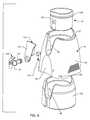
- FIG. 5is an exploded perspective view showing assembly of a lower portion of the beverage cooler
- FIG. 6is an exploded perspective view illustrating assembly of a removable beverage reservoir with a cooler housing and associated insulation
- FIG. 7is an exploded perspective view depicting assembly of an exemplary lid and filter with the removable reservoir
- FIG. 8is an exploded perspective view showing assembly of a thermoelectric chiller unit
- FIG. 9is a top perspective view showing the thermoelectric chiller unit in assembled form
- FIG. 10is a bottom perspective view of the thermoelectric chiller unit in assembled form
- FIG. 11is an enlarged vertical sectional view taken generally on the line 11 — 11 of FIG. 9;
- FIG. 12is a perspective view illustrating the thermoelectric chiller unit mounted on a housing base frame, and including light means;
- FIG. 13is an enlarged fragmented perspective view corresponding with the encircled region 13 of FIG. 4;
- FIG. 14is an enlarged fragmented perspective view corresponding with the encircled region 14 of FIG. 4 .
- a beverage cooler referred to generally by the reference numeral 10 in FIGS. 1-4includes a thermoelectric heat transfer module 12 (FIGS. 3-4) for chilling a selected beverage such as water or the like within a cooler reservoir 14 .
- the thermoelectric heat transfer module 12is provided as part of a relatively compact thermoelectric chiller unit or subassembly 16 (FIGS. 5 and 8 - 11 ) adapted for quick and easy mounting within a housing 18 for the cooler 10 .
- the cooler reservoir 14has a faucet 20 mounted thereon and exposed at a front side of the cooler housing 18 for on-demand dispensing of the reservoir contents. This reservoir 14 including the faucet 20 is quickly and easily removable as a unit from the cooler housing.
- the beverage cooler 10 depicted in the illustrative drawingscomprises a countertop type cooler having the housing 18 of compact size and shape suitable for placement onto a countertop (not shown).
- the housing 18has a generally rectangular or square-shaped base footprint which extends upwardly from a lower edge to define a front wall 22 , a rear wall 24 , and a pair of side walls 26 joined therebetween.
- These housing walls 22 , 24 and 26are shown to curve and converge slightly inwardly from bottom to top, and collectively define a contoured upper edge 27 designed for seated and stable support of an upper bowl-shaped portion 28 of the beverage reservoir 14 .
- this upper bowl-shaped reservoir portion 28is formed at the upper extent of a generally cylindrical lower reservoir portion 30 having a closed bottom wall 32 interrupted by a centrally formed upwardly extending receptacle 34 of generally inverted cup-shaped configuration (FIGS. 3 and 4 ).
- thermoelectric chiller unit 16generally comprises a pre-assembled unit installed within the cooler housing at a lower or bottom end thereof. As shown best in FIG. 5, the thermoelectric chiller unit 16 is mounted in overlying relation to a fan unit 38 , which is in turn mounted over a removable filter tray 40 .
- FIG. 5illustrates a lower base frame 42 having a size and shape for mounting within a lower region of the cooler housing 18 by means of screws (not shown) or the like.
- This base frame 42includes four downwardly protruding feet 44 disposed at the four corners of the housing footprint, wherein cushioned pads 46 may be conveniently mounted to the bottoms of these feet 44 .
- a lower slot 48(FIG. 4) is defined at the underside of the base frame 42 for lateral slide-fit removable mounting of the filter tray 40 having a selected porous filter media 50 (FIG. 5) carried thereon.
- This filter tray 40is removably mounted from the rear wall 24 of the cooler housing 18 (FIG. 2) in a manner shown and described in more detail in U.S. Pat. No. 6,003,318, which is incorporated by reference herein.
- the fan unit 38comprises a compact and generally pancake-shaped fan housing 52 with a low profile drive motor 54 and related fan impeller 56 mounted therein (FIGS. 3 - 5 ).
- the fan unit 38is mounted onto the upper side of the base frame 42 by means of screws (not shown) or the like in a position between a pair of upwardly extending frame ribs 58 and overlying an air inlet port 60 formed centrally in the base frame 42 (FIG. 5 ).
- the fan impeller 56draws ambient air from beneath the base frame 42 upwardly through the filter media 50 and further through the air inlet port 60 into heat transfer relation with the thermoelectric chiller unit 16 , as will be described.
- This cooling air flowis conveniently exhausted from the cooler housing 18 via air vents 62 formed in the housing side walls 26 near the lower ends thereof (FIG. 2 ).
- the base frame 42may also support an indicator light system for providing a visual indication that the filter media 50 on the filter tray 40 needs to be cleaned or changed to maintain optimum air flow circulation.
- a filter indicator light 140(FIGS. 1, 3 and 5 ) is mounted for viewing through a small port formed in the housing front wall 22 .
- this filter light 140is associated with a switch 142 (FIG. 5) which responds to slide-in insertion placement of the filter tray 40 to initiate a clock (which may be incorporated into a controller 92 , as will be described in more detail) for energizing the filter light 140 at the conclusion of a predetermined time interval, such as about 30 days.
- thermoelectric chiller unit 16is installed onto the base frame 42 by screws 64 (FIG. 3) or the like in a position directly overlying the fan unit 38 .
- the chiller unit 16comprises the thermoelectric heat transfer module 12 clamped in sandwiched relation between the overlying chiller probe 36 and an underlying heat exchanger or heat sink 66 .
- This thermoelectric heat transfer module 12comprises a relatively thin and generally flat-sided structure designed for transferring heat energy from a cold side to a hot side thereof, or vice versa, depending upon the polarity of a dc electrical signal connected thereto via a pair of conductors 67 (FIG. 8 ).
- heat transfer module 12is available form Borg-Warner Corporation under model designation 920-31, and employs semiconductor materials with dissimilar characteristics (P-type and N-type materials) connected electrically in series and thermally in parallel.
- the heat transfer module 12is clamped with substantially uniform distribution of clamping forces by means of a spring mount including an elongated spring clip or strip 68 and a pair of fasteners 70 such as screws.
- FIG. 8shows the heat sink 66 to include a generally planar backing plate 72 joined to an array of downwardly projecting heat dissipation fins 74 disposed to present an extended heat transfer surface area exposed to the cooling air flow circulation produced through the lower region of the housing 18 by the fan unit 38 .
- These fins 74are interrupted by a transversely extending and downwardly open slot 76 .
- the spring clip 68has a size and shape to fit into this slot 76 , with a central spring segment 78 offset from the strip plane and protruding upwardly from a central region of the spring strip 68 in a direction toward the underside of the heat sink backing plate 72 for bearing engagement therewith.
- the fasteners 70are passed upwardly through the opposite ends of the spring strip 68 , and further upwardly through a pair of ports 80 formed in the backing plate 72 on opposite sides of the thermoelectric module 12 .
- FIGS. 5 and 8 - 11show the winged base of the chiller probe 36 seated within an upwardly open and matingly shaped pocket 86 formed in a mounting collar 88 of thermal insulation material.
- This collar 88has a generally cylindrical shape, including a generally rectangular internal passage 90 for matingly receiving and positioning the thermoelectric module 12 (FIG. 11 ).
- the mounting collar 88is seated on the upper side of the heat sink backing plate 72 by means of the fasteners 70 , with a tab 89 upstanding on the backing plate 72 and received into a mating channel 91 (FIG. 8) for rotationally setting the collar 88 and the associated chiller probe 36 relative to the heat sink 66 .
- thermoelectric heat transfer module 12is clamped in stacked relation between an upper side of the heat sink backing plate 72 , and a lower side of the chiller probe 36 .
- This clamping actionis achieved by advancing the fasteners 70 through the opposite ends of the spring clip 68 , with the central spring segment 78 bearing against the underside of the heat sink backing plate 72 .
- thiscauses the opposite ends of the spring clip 68 to springably deform toward the backing plate, for purposes of drawing the chiller probe 36 downward into tightly clamped relation with the module 12 .
- this spring mount arrangementapplies substantially uniformly distributed clamping forces to the module 12 , irrespective of nonuniform relative advancement of the two fasteners 70 .
- the heat sink 66 and the chiller probe 36are formed from materials selected for relatively high thermal conductivity, such as aluminum or the like. With this construction, and by appropriately connecting a dc signal to the thermoelectric heat transfer module 12 , the module functions to draw or extract thermal energy from the chiller probe 36 at the module cold side and to transfer the extracted heat energy to the heat sink 66 at the module hot side.
- the controller 92(FIG. 5) is mounted onto the base frame 42 for appropriately supplying this dc signal to the module 12 , as well as providing and regulating electrical power to other cooler components, as previously described.
- the chiller unit 16When the chiller probe 36 is in thermal communication with the reservoir in contact with the inverted cup-shaped receptacle 34 which is in turn in contact with the reservoir contents, the chiller unit 16 thus operates to chill the beverage within the reservoir 14 to a pleasing and refreshing temperature.
- the reservoir 14is configured for seated reception into the cooler housing 18 , with the bottom wall receptacle 34 fitted over the upstanding chiller probe 36 of the thermoelectric chiller unit 16 . In this position, the chiller probe 36 is in thermal communication with the beverage contained within the reservoir to chill the reservoir contents.
- the lower portion 30 of the reservoir 14is nestably seated within the housing 18 , and an insulation shell 93 formed from a selected insulative material such as stryofoam or the like is slidably fitted upwardly into the housing 18 interior prior to installation of the lower base frame 42 .
- this insulation shell 93conveniently rests upon the upstanding frame ribs 58 , and has a central opening 94 in a bottom wall thereof for slide-fit reception of the mounting collar 88 of the chiller unit 16 .
- An upwardly open central gap 96is formed in the front wall 22 of the cooler housing 18 , in alignment with a correspondingly shaped central gap 98 formed in the insulation shell 93 , as viewed in FIGS. 3 and 5 - 7 .
- These gaps 96 , 98 in the housing structureaccommodate passage of a dispense conduit 100 having an inboard end suitably connected to the reservoir lower portion 30 , and an outboard end carrying the dispensing faucet 20 .
- a trim panel 101is carried on the dispense conduit 100 for visually closing the gap 96 in the housing 18 . Appropriate manipulation of a spring-loaded faucet handle 102 results in dispensing of the chilled reservoir contents.
- the inboard end of the dispense conduit 100may be coupled to a short dip tube 104 which extends downwardly to a point near the bottom wall 32 of the reservoir 14 .
- the dispensed beveragecomprises a portion of the reservoir contents disposed at or near the chiller probe 36 for optimal chilling prior to dispensing.
- An internal baffle disk 106(FIGS. 3-4 and 7 ) having a central aperture 108 therein may also be provided to subdivide the reservoir interior into a chilled lower chamber 110 (FIGS. 3-4) and an unchilled upper chamber 112 , so that the refrigeration capacity of the chiller unit 16 is focused upon a portion of the reservoir contents (within the lower chamber 110 ) for substantially optimized beverage chilling prior to individual dispense events.
- the chiller unit 16can be regulated by the controller 92 for producing an ice block (not shown) surrounding the receptacle 34 within the lower chamber 110 for optimized beverage chilling.
- An upper rim 114 (FIG. 7) of the reservoir bowl portion 28carries a removably mounted cap 116 (FIGS. 1-4 and 7 ), which preferably includes a peripheral seal engageable with the reservoir rim 114 .
- This cap 116in turn includes a central lid 118 mounted thereto by a pivot pin 120 or the like for pivoting movement between open and closed positions.
- a sealmay also be provided at the periphery of this lid 118 for engaging the cap 116 in the closed position.
- an air filter 124is also mounted on the cap 116 for filtering air drawn into the reservoir interior in response to beverage dispensing.
- the lid 118can be pivoted upwardly to an open position to permit an additional quantity of the selected beverage to be poured into the reservoir interior.
- the reservoir 14 with the faucet 20 mounted thereonis removable as a unit from the cooler housing 18 .
- the bowl-shaped upper portion 28 of the reservoir 14conveniently includes externally accessible, indented hand grips 126 for facilitated manual grasping upon lift-out removal of the reservoir 14 from the cooler housing. Since the faucet 20 remains on the reservoir upon such removal, it is not necessary to drain the contents of the reservoir prior to removal for cleaning or the like.
- the reservoir 14is quickly and easily re-installed into the housing 18 by simple drop-in, slide-fit placement with the chiller probe 36 seated into the receptacle 34 at the underside of the reservoir.
- a raised seal ring 128may be provided on an interior wall 19 of the housing 18 for engaging the exterior of the reservoir lower portion 30 near the upper margin thereof when the reservoir is installed therein. This seal ring 128 minimizes or prevents ingress of moisture-laden air into the any incremental space between the exterior surfaces of the reservoir portion 30 and the interior surfaces of the housing wall 19 engaged therewith.
- An additional seal ring 129(FIG. 13) may also be provided generally at the base of the receptacle 34 for engaging the chiller probe 36 near the lower end thereof to minimize or eliminate air ingress into any residual space between the receptacle and the upstanding chiller probe 36 , in the manner disclosed and described in U.S. Pat. No.
- seal ring 128can be formed on the reservoir 14 for engaging the internal housing wall 19
- seal ring 129can be formed on the chiller probe 36 for engaging the interior surface of the receptacle 34 , if desired.
- Lighting meansmay also be provided to produce an enhanced cooler appearance, particularly at night or low light level conditions.
- FIG. 12shows the thermoelectric chiller unit 16 mounted on the housing base frame 42 , with a pair of LED lights 130 fitted into shallow cavities 132 formed within each of the frame feet 44 at the front corners of the cooler housing. These lights 130 are positioned behind translucent or transparent foot panels 134 exposed through recesses 136 (FIG. 6) at the housing corners, when the housing 18 is assembled with the base frame 42 .
- An additional light 138such as an LED light or light pipe, may also be provided at an upper end of a vertically elongated support post 139 (FIG. 12) or the like, to position the additional light 138 (FIG. 1) behind the trim panel 101 of translucent or transparent construction.
- These lights 130 and 138provide externally visible illumination through the associated overlying translucent or transparent panels to provide an attractive cooler appearance, and further to provide sufficient light for facilitated night-time cooler operation.
- thermoelectric beverage cooler of the present inventionA variety of further modifications and improvements in and to the thermoelectric beverage cooler of the present invention will be apparent to those persons skilled in the art.
- alternative reservoir configurationsmay be used for supporting an inverted water supply bottle of the type and manner of a conventional bottled water cooler.
- the reservoir cap structuremay incorporate a filter element for filtering contaminants from a selected beverage such as water poured into the reservoir. Accordingly, no limitation on the invention is intended by way of the foregoing description and accompanying drawings, except as set forth in the appended claims.
Landscapes
- Engineering & Computer Science (AREA)
- Mechanical Engineering (AREA)
- Physics & Mathematics (AREA)
- Thermal Sciences (AREA)
- General Engineering & Computer Science (AREA)
- Chemical & Material Sciences (AREA)
- Combustion & Propulsion (AREA)
- Devices That Are Associated With Refrigeration Equipment (AREA)
Abstract
Description
Claims (29)
Priority Applications (1)
| Application Number | Priority Date | Filing Date | Title |
|---|---|---|---|
| US10/255,554US6644037B2 (en) | 2001-09-26 | 2002-09-25 | Thermoelectric beverage cooler |
Applications Claiming Priority (2)
| Application Number | Priority Date | Filing Date | Title |
|---|---|---|---|
| US32548401P | 2001-09-26 | 2001-09-26 | |
| US10/255,554US6644037B2 (en) | 2001-09-26 | 2002-09-25 | Thermoelectric beverage cooler |
Publications (2)
| Publication Number | Publication Date |
|---|---|
| US20030115902A1 US20030115902A1 (en) | 2003-06-26 |
| US6644037B2true US6644037B2 (en) | 2003-11-11 |
Family
ID=23268068
Family Applications (1)
| Application Number | Title | Priority Date | Filing Date |
|---|---|---|---|
| US10/255,554Expired - Fee RelatedUS6644037B2 (en) | 2001-09-26 | 2002-09-25 | Thermoelectric beverage cooler |
Country Status (5)
| Country | Link |
|---|---|
| US (1) | US6644037B2 (en) |
| EP (1) | EP1430257A2 (en) |
| CA (1) | CA2460532A1 (en) |
| MX (1) | MXPA04002850A (en) |
| WO (1) | WO2003027582A2 (en) |
Cited By (14)
| Publication number | Priority date | Publication date | Assignee | Title |
|---|---|---|---|---|
| US20060075761A1 (en)* | 2004-10-07 | 2006-04-13 | Kitchens Mark C | Apparatus for cooled or heated on demand drinking water and process for making same |
| US7237390B1 (en)* | 2005-04-21 | 2007-07-03 | Lance Nelson | Compact portable beverage cooling system |
| US20070193280A1 (en)* | 2004-10-22 | 2007-08-23 | Tuskiewicz George A | Portable cooled merchandizing unit with customer enticement features |
| US20080092583A1 (en)* | 2006-10-24 | 2008-04-24 | Shae Hong | Beverage fountain with removable freezable member |
| US20090229293A1 (en)* | 2004-10-29 | 2009-09-17 | Byung-Chul Kim | Cooler of Table-Type |
| USD703990S1 (en)* | 2012-08-02 | 2014-05-06 | Jeffrey D Henderson | Beverage dispenser for alcoholic beverages |
| US10145592B2 (en) | 2014-07-15 | 2018-12-04 | Dometic Sweden Ab | Beverage cooler and heater assembly |
| WO2019070948A1 (en)* | 2017-10-05 | 2019-04-11 | Vitafilta, Inc. | Water cooler with filter |
| US20200085011A1 (en)* | 2018-09-19 | 2020-03-19 | Lg Electronics Inc. | Liquid dispenser having fan housing |
| US11653627B2 (en) | 2018-09-19 | 2023-05-23 | Lg Electronics Inc. | Liquid dispenser for animals |
| US11659813B2 (en) | 2018-09-19 | 2023-05-30 | Lg Electronics Inc. | Liquid dispenser for animals |
| US11771058B2 (en) | 2018-09-19 | 2023-10-03 | Lg Electronics Inc. | Liquid dispenser for animals |
| US11793160B2 (en) | 2018-09-19 | 2023-10-24 | Lg Electronics Inc. | Liquid dispenser for animals |
| US11871732B2 (en) | 2018-09-19 | 2024-01-16 | Lg Electronics Inc. | Liquid dispenser for animals |
Families Citing this family (24)
| Publication number | Priority date | Publication date | Assignee | Title |
|---|---|---|---|---|
| US7451603B2 (en) | 2004-03-22 | 2008-11-18 | General Mills, Inc. | Portable cooled merchandizing unit |
| DE102004035732A1 (en)* | 2004-07-23 | 2006-03-16 | BSH Bosch und Siemens Hausgeräte GmbH | Refrigeration device and Peltier cooling device for it |
| FR2875225B1 (en)* | 2004-09-15 | 2006-12-08 | Mistral Constructeur Soc Par A | LOW-DENSITY WATER FOUNTAIN |
| DE102007029188A1 (en)* | 2007-06-25 | 2009-01-08 | BSH Bosch und Siemens Hausgeräte GmbH | The refrigerator |
| DE102008027527A1 (en) | 2008-01-02 | 2009-07-16 | Reinhard Hartung | Drink dispenser |
| US8468836B2 (en)* | 2008-11-12 | 2013-06-25 | General Mills, Inc. | Portable thermoelectric cooling/heating unit and related merchandizing system |
| USD615319S1 (en) | 2008-11-12 | 2010-05-11 | General Mills, Inc. | Product merchandizing unit |
| US20100258268A1 (en)* | 2009-04-12 | 2010-10-14 | Hsin-Jen Li | Temperature adjustable cup holder having memory card readable function |
| US8887512B2 (en) | 2011-06-08 | 2014-11-18 | Richard Elliot Olsen | Cooler for temperature sensitive items |
| JP5529200B2 (en)* | 2012-04-02 | 2014-06-25 | 株式会社コスモライフ | Water server |
| US9828231B2 (en)* | 2013-03-20 | 2017-11-28 | BAM! & Co., LLC | Apparatus for storing and dispensing wine |
| DE102013016983B4 (en)* | 2013-10-14 | 2017-04-27 | Eckes-Granini Group Gmbh | Device for dispensing beverages |
| US11493269B2 (en)* | 2014-08-22 | 2022-11-08 | Roasting Plant, Inc. | Beverage chiller and associated systems and methods |
| JP6698380B2 (en)* | 2016-03-02 | 2020-05-27 | アサヒビール株式会社 | Beverage server |
| NL2017109B1 (en) | 2016-07-05 | 2018-01-12 | Heineken Supply Chain Bv | Beverage dispensing assembly and beverage container |
| NL2018955B1 (en)* | 2017-05-19 | 2018-11-28 | Heineken Supply Chain Bv | Beverage dispensing assembly and beverage container |
| NL2018956B1 (en)* | 2017-05-19 | 2018-11-28 | Heineken Supply Chain Bv | Beverage dispensing assembly and beverage container |
| US11596127B2 (en) | 2018-09-19 | 2023-03-07 | Lg Electronics Inc. | Liquid dispenser for animals |
| US11565202B2 (en) | 2018-09-19 | 2023-01-31 | Lg Electronics Inc. | Liquid dispenser for animals |
| US11659812B2 (en) | 2018-09-19 | 2023-05-30 | Lg Electronics Inc. | Liquid dispenser for animals |
| US11590438B2 (en) | 2018-09-19 | 2023-02-28 | Lg Electronics Inc. | Liquid dispenser for animals |
| US11527906B2 (en) | 2018-09-19 | 2022-12-13 | Lg Electronics Inc. | Liquid dispenser for animals |
| CN111481055A (en)* | 2020-03-25 | 2020-08-04 | 张文丞 | a beverage maker |
| CN120348899A (en)* | 2024-01-22 | 2025-07-22 | 施特劳斯净水有限公司 | Portable water dispenser |
Citations (7)
| Publication number | Priority date | Publication date | Assignee | Title |
|---|---|---|---|---|
| US2657554A (en)* | 1951-08-21 | 1953-11-03 | Roy F Steward | Liquid dispenser |
| US4622822A (en)* | 1984-05-07 | 1986-11-18 | Shlomo Beitner | Peltier thermoelectric element mounting |
| US5072590A (en) | 1991-02-11 | 1991-12-17 | Ebtech, Inc. | Bottled water chilling system |
| US5355678A (en)* | 1993-05-19 | 1994-10-18 | Shlomo Beitner | Thermoelectric element mounting apparatus |
| US6003318A (en) | 1998-04-28 | 1999-12-21 | Oasis Corporation | Thermoelectric water cooler |
| US6119462A (en) | 1998-03-23 | 2000-09-19 | Oasis Corporation | Water cooler with improved thermoelectric chiller system |
| US6532746B1 (en)* | 2002-01-24 | 2003-03-18 | Tyco Telecommunications (Us) Inc. | Method and apparatus for securing an electronic component |
Family Cites Families (3)
| Publication number | Priority date | Publication date | Assignee | Title |
|---|---|---|---|---|
| US5572872A (en)* | 1994-08-15 | 1996-11-12 | Hlavacek; Robert A. | Liquid cooling, storing and dispensing device |
| WO1999054250A2 (en)* | 1998-04-17 | 1999-10-28 | Home Pure L.L.C. | Water cooler and dispenser |
| US6370884B1 (en)* | 2001-03-30 | 2002-04-16 | Maher I. Kelada | Thermoelectric fluid cooling cartridge |
- 2002
- 2002-09-25USUS10/255,554patent/US6644037B2/ennot_activeExpired - Fee Related
- 2002-09-26MXMXPA04002850Apatent/MXPA04002850A/enunknown
- 2002-09-26WOPCT/US2002/030976patent/WO2003027582A2/ennot_activeApplication Discontinuation
- 2002-09-26EPEP02776045Apatent/EP1430257A2/ennot_activeWithdrawn
- 2002-09-26CACA002460532Apatent/CA2460532A1/ennot_activeAbandoned
Patent Citations (7)
| Publication number | Priority date | Publication date | Assignee | Title |
|---|---|---|---|---|
| US2657554A (en)* | 1951-08-21 | 1953-11-03 | Roy F Steward | Liquid dispenser |
| US4622822A (en)* | 1984-05-07 | 1986-11-18 | Shlomo Beitner | Peltier thermoelectric element mounting |
| US5072590A (en) | 1991-02-11 | 1991-12-17 | Ebtech, Inc. | Bottled water chilling system |
| US5355678A (en)* | 1993-05-19 | 1994-10-18 | Shlomo Beitner | Thermoelectric element mounting apparatus |
| US6119462A (en) | 1998-03-23 | 2000-09-19 | Oasis Corporation | Water cooler with improved thermoelectric chiller system |
| US6003318A (en) | 1998-04-28 | 1999-12-21 | Oasis Corporation | Thermoelectric water cooler |
| US6532746B1 (en)* | 2002-01-24 | 2003-03-18 | Tyco Telecommunications (Us) Inc. | Method and apparatus for securing an electronic component |
Cited By (20)
| Publication number | Priority date | Publication date | Assignee | Title |
|---|---|---|---|---|
| US20060075761A1 (en)* | 2004-10-07 | 2006-04-13 | Kitchens Mark C | Apparatus for cooled or heated on demand drinking water and process for making same |
| US20070193280A1 (en)* | 2004-10-22 | 2007-08-23 | Tuskiewicz George A | Portable cooled merchandizing unit with customer enticement features |
| US7934384B2 (en)* | 2004-10-22 | 2011-05-03 | General Mills, Inc. | Portable cooled merchandizing unit with customer enticement features |
| US20090229293A1 (en)* | 2004-10-29 | 2009-09-17 | Byung-Chul Kim | Cooler of Table-Type |
| US7237390B1 (en)* | 2005-04-21 | 2007-07-03 | Lance Nelson | Compact portable beverage cooling system |
| US20080092583A1 (en)* | 2006-10-24 | 2008-04-24 | Shae Hong | Beverage fountain with removable freezable member |
| USD703990S1 (en)* | 2012-08-02 | 2014-05-06 | Jeffrey D Henderson | Beverage dispenser for alcoholic beverages |
| US10145592B2 (en) | 2014-07-15 | 2018-12-04 | Dometic Sweden Ab | Beverage cooler and heater assembly |
| US10562429B2 (en) | 2014-07-15 | 2020-02-18 | Dometic Sweden Ab | Beverage cooler and heater assembly |
| WO2019070948A1 (en)* | 2017-10-05 | 2019-04-11 | Vitafilta, Inc. | Water cooler with filter |
| US20200085011A1 (en)* | 2018-09-19 | 2020-03-19 | Lg Electronics Inc. | Liquid dispenser having fan housing |
| US11653627B2 (en) | 2018-09-19 | 2023-05-23 | Lg Electronics Inc. | Liquid dispenser for animals |
| US11659813B2 (en) | 2018-09-19 | 2023-05-30 | Lg Electronics Inc. | Liquid dispenser for animals |
| US11766026B2 (en) | 2018-09-19 | 2023-09-26 | Lg Electronics Inc. | Liquid dispenser for animals |
| US11771058B2 (en) | 2018-09-19 | 2023-10-03 | Lg Electronics Inc. | Liquid dispenser for animals |
| US11793160B2 (en) | 2018-09-19 | 2023-10-24 | Lg Electronics Inc. | Liquid dispenser for animals |
| US11839202B2 (en) | 2018-09-19 | 2023-12-12 | Lg Electronics Inc. | Liquid dispenser having container |
| US11871732B2 (en) | 2018-09-19 | 2024-01-16 | Lg Electronics Inc. | Liquid dispenser for animals |
| US12127538B2 (en) | 2018-09-19 | 2024-10-29 | Lg Electronics Inc. | Liquid dispenser having pump cover and filter |
| US12193422B2 (en)* | 2018-09-19 | 2025-01-14 | Lg Electronics Inc. | Liquid dispenser having fan housing |
Also Published As
| Publication number | Publication date |
|---|---|
| US20030115902A1 (en) | 2003-06-26 |
| EP1430257A2 (en) | 2004-06-23 |
| CA2460532A1 (en) | 2003-04-03 |
| WO2003027582A2 (en) | 2003-04-03 |
| MXPA04002850A (en) | 2004-07-05 |
| WO2003027582A3 (en) | 2003-12-11 |
Similar Documents
| Publication | Publication Date | Title |
|---|---|---|
| US6644037B2 (en) | Thermoelectric beverage cooler | |
| US6003318A (en) | Thermoelectric water cooler | |
| US4752389A (en) | Water purification system with purified water cooling apparatus | |
| US4993229A (en) | Bottled water cooling unit | |
| US20040134932A1 (en) | Beverage dispenser | |
| US5699669A (en) | Air-circulating base for bottled water cooling and dispensing apparatus | |
| US5072590A (en) | Bottled water chilling system | |
| US4629096A (en) | Liquid dispenser with readily removable liquid container | |
| US6032481A (en) | Thermoregulating container | |
| US5246141A (en) | Bottled water station with removable reservoir | |
| US5333759A (en) | Modular dispensing tower | |
| US6119462A (en) | Water cooler with improved thermoelectric chiller system | |
| US5307958A (en) | Bottled water station with removable reservoir | |
| AU681265B2 (en) | Bottled water station with removable reservoir and manifolded support platform | |
| US3698603A (en) | Water-distributing system for a hot and cold drinking water dispenser | |
| GB2152011A (en) | Post-mix beverage dispenser with cooled water and syrup | |
| AU2002341890A1 (en) | Thermoelectric beverage cooler | |
| KR100915322B1 (en) | Cooling apparatus for drinking liquid | |
| JPS60183390A (en) | Distributor for drink | |
| US4854655A (en) | Cabinet and method of assembly of a beverage dispenser | |
| KR100860929B1 (en) | Drinking water cooler | |
| KR100821492B1 (en) | Drinking water cooler | |
| WO2020148560A1 (en) | Container for bag dispenser with refrigerator | |
| CN100467979C (en) | Small-sized drinking machine | |
| RU97102937A (en) | DRINKING WATER COOLER |
Legal Events
| Date | Code | Title | Description |
|---|---|---|---|
| AS | Assignment | Owner name:HARRIS TRUST AND SAVINGS BANK, AS AGENT, ILLINOIS Free format text:SECURITY INTEREST;ASSIGNOR:OASIS CORPORATION;REEL/FRAME:013767/0381 Effective date:20030224 | |
| AS | Assignment | Owner name:OASIS CORPORATION, OHIO Free format text:ASSIGNMENT OF ASSIGNORS INTEREST;ASSIGNORS:BUSICK, LOUIS M.;WHARTON, STEPHEN W.;SABIN, STEPHEN J.;AND OTHERS;REEL/FRAME:014376/0985;SIGNING DATES FROM 20030203 TO 20030215 | |
| AS | Assignment | Owner name:CONGRESS FINANCIAL CORPORATION (CENTRAL), ILLINOIS Free format text:SECURITY INTEREST;ASSIGNOR:OASIS CORPORATION;REEL/FRAME:016377/0194 Effective date:20050210 | |
| AS | Assignment | Owner name:OASIS CORPORATION, OHIO Free format text:RELEASE BY SECURED PARTY;ASSIGNOR:HARRIS TRUST AND SAVINGS BANK, AS AGENT;REEL/FRAME:016345/0493 Effective date:20050210 | |
| AS | Assignment | Owner name:ZOHAR WATERWORKS, LLC, NORTH CAROLINA Free format text:ASSIGNMENT OF ASSIGNORS INTEREST;ASSIGNOR:OASIS CORPORATION;REEL/FRAME:016761/0818 Effective date:20050826 | |
| AS | Assignment | Owner name:PATRIARCH PARTNERS AGENCY SERVICES, LLC, NORTH CAR Free format text:SECURITY INTEREST;ASSIGNOR:ZOHAR WATERWORKS, LLC;REEL/FRAME:016993/0250 Effective date:20050826 | |
| XAS | Not any more in us assignment database | Free format text:SECURITY INTEREST;ASSIGNOR:ZOHAR WATERWORKS, LLC;REEL/FRAME:016993/0250 | |
| FPAY | Fee payment | Year of fee payment:4 | |
| SULP | Surcharge for late payment | ||
| FEPP | Fee payment procedure | Free format text:PAYOR NUMBER ASSIGNED (ORIGINAL EVENT CODE: ASPN); ENTITY STATUS OF PATENT OWNER: LARGE ENTITY | |
| AS | Assignment | Owner name:LVD ACQUISITION, LLC, OHIO Free format text:ASSIGNMENT OF ASSIGNORS INTEREST;ASSIGNOR:ZOHAR WATERWORKS LLC;REEL/FRAME:022846/0960 Effective date:20090601 | |
| AS | Assignment | Owner name:PATRIARCH PARTNERS AGENCY SERVICES, LLC,NEW YORK Free format text:SECURITY AGREEMENT;ASSIGNOR:LVD ACQUISITION, LLC;REEL/FRAME:024233/0787 Effective date:20090601 | |
| FPAY | Fee payment | Year of fee payment:8 | |
| REMI | Maintenance fee reminder mailed | ||
| LAPS | Lapse for failure to pay maintenance fees | ||
| STCH | Information on status: patent discontinuation | Free format text:PATENT EXPIRED DUE TO NONPAYMENT OF MAINTENANCE FEES UNDER 37 CFR 1.362 | |
| FP | Lapsed due to failure to pay maintenance fee | Effective date:20151111 | |
| AS | Assignment | Owner name:LVD ACQUISITION, LLC, OHIO Free format text:TERMINATION AND RELEASE OF SECURITY INTEREST IN INTELLECTUAL PROPERTY;ASSIGNOR:ANKURA TRUST COMPANY, LLC, AS SUCCESSOR AGENT TO PATRIARCH PARTNERS AGENCY SERVICES, LLC;REEL/FRAME:050593/0691 Effective date:20190930 |