US6643552B2 - Implantable devices having a liquid crystal polymer substrate - Google Patents
Implantable devices having a liquid crystal polymer substrateDownload PDFInfo
- Publication number
- US6643552B2 US6643552B2US10/158,510US15851002AUS6643552B2US 6643552 B2US6643552 B2US 6643552B2US 15851002 AUS15851002 AUS 15851002AUS 6643552 B2US6643552 B2US 6643552B2
- Authority
- US
- United States
- Prior art keywords
- electrode
- substrate
- lcp
- conductor
- interconnect
- Prior art date
- Legal status (The legal status is an assumption and is not a legal conclusion. Google has not performed a legal analysis and makes no representation as to the accuracy of the status listed.)
- Expired - Fee Related
Links
- 239000000758substrateSubstances0.000titleclaimsabstractdescription122
- 229920000106Liquid crystal polymerPolymers0.000titleabstractdescription90
- 239000004977Liquid-crystal polymers (LCPs)Substances0.000titleabstractdescription79
- 239000004020conductorSubstances0.000claimsabstractdescription122
- 239000008393encapsulating agentSubstances0.000claimsabstractdescription44
- 229920001296polysiloxanePolymers0.000claimsdescription15
- 239000010703siliconSubstances0.000claimsdescription9
- 229910052710siliconInorganic materials0.000claimsdescription9
- 238000012545processingMethods0.000abstractdescription8
- 229920005573silicon-containing polymerPolymers0.000abstractdescription6
- 230000003750conditioning effectEffects0.000abstractdescription4
- 239000000463materialSubstances0.000description18
- 238000000034methodMethods0.000description11
- 210000001519tissueAnatomy0.000description10
- XUIMIQQOPSSXEZ-UHFFFAOYSA-NSiliconChemical compound[Si]XUIMIQQOPSSXEZ-UHFFFAOYSA-N0.000description8
- 230000001537neural effectEffects0.000description7
- 239000004642PolyimideSubstances0.000description6
- 229920001721polyimidePolymers0.000description6
- 239000004944Liquid Silicone RubberSubstances0.000description5
- 238000000576coating methodMethods0.000description5
- 210000005257cortical tissueAnatomy0.000description5
- 239000010408filmSubstances0.000description5
- 229920002379silicone rubberPolymers0.000description5
- 230000004888barrier functionEffects0.000description4
- 230000000747cardiac effectEffects0.000description4
- 239000011248coating agentSubstances0.000description4
- 229910052751metalInorganic materials0.000description4
- 239000002184metalSubstances0.000description4
- 229920002120photoresistant polymerPolymers0.000description4
- 239000000126substanceSubstances0.000description4
- 230000001133accelerationEffects0.000description3
- 238000003491arrayMethods0.000description3
- 210000002808connective tissueAnatomy0.000description3
- 239000011521glassSubstances0.000description3
- 238000007654immersionMethods0.000description3
- 239000004973liquid crystal related substanceSubstances0.000description3
- 230000033001locomotionEffects0.000description3
- 238000004377microelectronicMethods0.000description3
- 229920000642polymerPolymers0.000description3
- 210000000278spinal cordAnatomy0.000description3
- XLYOFNOQVPJJNP-UHFFFAOYSA-NwaterSubstancesOXLYOFNOQVPJJNP-UHFFFAOYSA-N0.000description3
- PXHVJJICTQNCMI-UHFFFAOYSA-NNickelChemical compound[Ni]PXHVJJICTQNCMI-UHFFFAOYSA-N0.000description2
- FAPWRFPIFSIZLT-UHFFFAOYSA-MSodium chlorideChemical compound[Na+].[Cl-]FAPWRFPIFSIZLT-UHFFFAOYSA-M0.000description2
- RTAQQCXQSZGOHL-UHFFFAOYSA-NTitaniumChemical compound[Ti]RTAQQCXQSZGOHL-UHFFFAOYSA-N0.000description2
- QVGXLLKOCUKJST-UHFFFAOYSA-Natomic oxygenChemical compound[O]QVGXLLKOCUKJST-UHFFFAOYSA-N0.000description2
- 210000004556brainAnatomy0.000description2
- 230000015556catabolic processEffects0.000description2
- 210000004027cellAnatomy0.000description2
- 238000005260corrosionMethods0.000description2
- 230000007797corrosionEffects0.000description2
- 230000001054cortical effectEffects0.000description2
- 238000006731degradation reactionMethods0.000description2
- 230000001419dependent effectEffects0.000description2
- 238000000151depositionMethods0.000description2
- 230000008021depositionEffects0.000description2
- 238000005538encapsulationMethods0.000description2
- 238000005516engineering processMethods0.000description2
- 238000007687exposure techniqueMethods0.000description2
- 239000012530fluidSubstances0.000description2
- 238000002513implantationMethods0.000description2
- 239000007788liquidSubstances0.000description2
- 230000007774longtermEffects0.000description2
- 230000000873masking effectEffects0.000description2
- 239000000155meltSubstances0.000description2
- 239000000178monomerSubstances0.000description2
- 210000002569neuronAnatomy0.000description2
- 239000001301oxygenSubstances0.000description2
- 229910052760oxygenInorganic materials0.000description2
- 210000000578peripheral nerveAnatomy0.000description2
- 230000035699permeabilityEffects0.000description2
- BASFCYQUMIYNBI-UHFFFAOYSA-NplatinumChemical compound[Pt]BASFCYQUMIYNBI-UHFFFAOYSA-N0.000description2
- 239000011780sodium chlorideSubstances0.000description2
- 239000000243solutionSubstances0.000description2
- 239000002904solventSubstances0.000description2
- 238000004528spin coatingMethods0.000description2
- 230000004936stimulating effectEffects0.000description2
- 239000010936titaniumSubstances0.000description2
- 229910052719titaniumInorganic materials0.000description2
- GTKQZGZLLAXKMQ-UHFFFAOYSA-N*.COC1=CC=C(C(=O)OC2=CC3=C(C=C2)C=C(C(C)=O)C=C3)C=C1.[Y]Chemical compound*.COC1=CC=C(C(=O)OC2=CC3=C(C=C2)C=C(C(C)=O)C=C3)C=C1.[Y]GTKQZGZLLAXKMQ-UHFFFAOYSA-N0.000description1
- 206010011878DeafnessDiseases0.000description1
- 229910001111Fine metalInorganic materials0.000description1
- ATJFFYVFTNAWJD-UHFFFAOYSA-NTinChemical compound[Sn]ATJFFYVFTNAWJD-UHFFFAOYSA-N0.000description1
- 238000010521absorption reactionMethods0.000description1
- 230000003321amplificationEffects0.000description1
- 238000013459approachMethods0.000description1
- 230000005540biological transmissionEffects0.000description1
- 230000015572biosynthetic processEffects0.000description1
- 230000001684chronic effectEffects0.000description1
- 238000011109contaminationMethods0.000description1
- 229920001577copolymerPolymers0.000description1
- 239000013078crystalSubstances0.000description1
- 238000011161developmentMethods0.000description1
- 239000003989dielectric materialSubstances0.000description1
- 238000003618dip coatingMethods0.000description1
- 230000000694effectsEffects0.000description1
- 238000004100electronic packagingMethods0.000description1
- 238000009713electroplatingMethods0.000description1
- 238000001704evaporationMethods0.000description1
- 239000007789gasSubstances0.000description1
- 210000003128headAnatomy0.000description1
- 230000035876healingEffects0.000description1
- 239000003845household chemicalSubstances0.000description1
- 229930195733hydrocarbonNatural products0.000description1
- 150000002430hydrocarbonsChemical class0.000description1
- 230000003301hydrolyzing effectEffects0.000description1
- 238000001727in vivoMethods0.000description1
- 239000003317industrial substanceSubstances0.000description1
- 238000003780insertionMethods0.000description1
- 230000037431insertionEffects0.000description1
- 238000000608laser ablationMethods0.000description1
- 238000005459micromachiningMethods0.000description1
- 239000000203mixtureSubstances0.000description1
- 238000012986modificationMethods0.000description1
- 230000004048modificationEffects0.000description1
- 210000004165myocardiumAnatomy0.000description1
- 210000005036nerveAnatomy0.000description1
- 210000000653nervous systemAnatomy0.000description1
- 229910052759nickelInorganic materials0.000description1
- 238000003199nucleic acid amplification methodMethods0.000description1
- 239000003921oilSubstances0.000description1
- 238000004806packaging method and processMethods0.000description1
- 238000012856packingMethods0.000description1
- 238000000059patterningMethods0.000description1
- 150000002978peroxidesChemical class0.000description1
- 230000000704physical effectEffects0.000description1
- 239000002504physiological saline solutionSubstances0.000description1
- 229910052697platinumInorganic materials0.000description1
- 230000035755proliferationEffects0.000description1
- 230000002035prolonged effectEffects0.000description1
- 238000011160researchMethods0.000description1
- 210000001525retinaAnatomy0.000description1
- 230000002207retinal effectEffects0.000description1
- 210000003625skullAnatomy0.000description1
- 239000007921spraySubstances0.000description1
- 238000005507sprayingMethods0.000description1
- 238000004544sputter depositionMethods0.000description1
- 229910001256stainless steel alloyInorganic materials0.000description1
- 238000010561standard procedureMethods0.000description1
- 230000003068static effectEffects0.000description1
- 230000000638stimulationEffects0.000description1
- 239000010409thin filmSubstances0.000description1
- 239000011800void materialSubstances0.000description1
- 239000002982water resistant materialSubstances0.000description1
- 230000003313weakening effectEffects0.000description1
- 229910052727yttriumInorganic materials0.000description1
Images


Classifications
- A—HUMAN NECESSITIES
- A61—MEDICAL OR VETERINARY SCIENCE; HYGIENE
- A61N—ELECTROTHERAPY; MAGNETOTHERAPY; RADIATION THERAPY; ULTRASOUND THERAPY
- A61N1/00—Electrotherapy; Circuits therefor
- A61N1/02—Details
- A61N1/04—Electrodes
- A61N1/05—Electrodes for implantation or insertion into the body, e.g. heart electrode
- A61N1/0551—Spinal or peripheral nerve electrodes
- A—HUMAN NECESSITIES
- A61—MEDICAL OR VETERINARY SCIENCE; HYGIENE
- A61N—ELECTROTHERAPY; MAGNETOTHERAPY; RADIATION THERAPY; ULTRASOUND THERAPY
- A61N1/00—Electrotherapy; Circuits therefor
- A61N1/02—Details
- A61N1/04—Electrodes
- A61N1/05—Electrodes for implantation or insertion into the body, e.g. heart electrode
- A61N1/0526—Head electrodes
- A61N1/0529—Electrodes for brain stimulation
- A61N1/0531—Brain cortex electrodes
- A—HUMAN NECESSITIES
- A61—MEDICAL OR VETERINARY SCIENCE; HYGIENE
- A61N—ELECTROTHERAPY; MAGNETOTHERAPY; RADIATION THERAPY; ULTRASOUND THERAPY
- A61N1/00—Electrotherapy; Circuits therefor
- A61N1/02—Details
- A61N1/04—Electrodes
- A61N1/05—Electrodes for implantation or insertion into the body, e.g. heart electrode
- A61N1/0526—Head electrodes
- A61N1/0529—Electrodes for brain stimulation
- A61N1/0534—Electrodes for deep brain stimulation
- A—HUMAN NECESSITIES
- A61—MEDICAL OR VETERINARY SCIENCE; HYGIENE
- A61N—ELECTROTHERAPY; MAGNETOTHERAPY; RADIATION THERAPY; ULTRASOUND THERAPY
- A61N1/00—Electrotherapy; Circuits therefor
- A61N1/02—Details
- A61N1/04—Electrodes
- A61N1/05—Electrodes for implantation or insertion into the body, e.g. heart electrode
- A61N1/0526—Head electrodes
- A61N1/0529—Electrodes for brain stimulation
- A61N1/0539—Anchoring of brain electrode systems, e.g. within burr hole
- A—HUMAN NECESSITIES
- A61—MEDICAL OR VETERINARY SCIENCE; HYGIENE
- A61N—ELECTROTHERAPY; MAGNETOTHERAPY; RADIATION THERAPY; ULTRASOUND THERAPY
- A61N1/00—Electrotherapy; Circuits therefor
- A61N1/02—Details
- A61N1/04—Electrodes
- A61N1/05—Electrodes for implantation or insertion into the body, e.g. heart electrode
- A61N1/0526—Head electrodes
- A61N1/0541—Cochlear electrodes
- A—HUMAN NECESSITIES
- A61—MEDICAL OR VETERINARY SCIENCE; HYGIENE
- A61N—ELECTROTHERAPY; MAGNETOTHERAPY; RADIATION THERAPY; ULTRASOUND THERAPY
- A61N1/00—Electrotherapy; Circuits therefor
- A61N1/02—Details
- A61N1/04—Electrodes
- A61N1/05—Electrodes for implantation or insertion into the body, e.g. heart electrode
- A61N1/0526—Head electrodes
- A61N1/0543—Retinal electrodes
- A—HUMAN NECESSITIES
- A61—MEDICAL OR VETERINARY SCIENCE; HYGIENE
- A61N—ELECTROTHERAPY; MAGNETOTHERAPY; RADIATION THERAPY; ULTRASOUND THERAPY
- A61N1/00—Electrotherapy; Circuits therefor
- A61N1/02—Details
- A61N1/04—Electrodes
- A61N1/05—Electrodes for implantation or insertion into the body, e.g. heart electrode
- A61N1/0551—Spinal or peripheral nerve electrodes
- A61N1/0553—Paddle shaped electrodes, e.g. for laminotomy
- A—HUMAN NECESSITIES
- A61—MEDICAL OR VETERINARY SCIENCE; HYGIENE
- A61N—ELECTROTHERAPY; MAGNETOTHERAPY; RADIATION THERAPY; ULTRASOUND THERAPY
- A61N1/00—Electrotherapy; Circuits therefor
- A61N1/02—Details
- A61N1/04—Electrodes
- A61N1/05—Electrodes for implantation or insertion into the body, e.g. heart electrode
- A61N1/0551—Spinal or peripheral nerve electrodes
- A61N1/0558—Anchoring or fixation means therefor
Definitions
- This inventionrelates generally to implantable electrodes and electronic hybrid circuits and in particular to implantable electrodes and electronic hybrid circuits having a liquid crystal substrate.
- IMDsimplantable medical devices
- cardiac pacemakerscochlear prosthesis devices
- neuroprosthesesneuroprostheses
- IMDscan be constructed using a variety of well known methods such as printed circuit boards and hybrid circuits formed on a substrate. Typical hybrid circuits are used can be formed using well known techniques. As the device size and conductor size decrease to below approximately 10 micrometers, the hybrid substrate must be micro-machined using photolithographic techniques to pattern and put down the conductor traces. An IMD needs to be encased with an encapsulant such as silicone that is chemically bonded to the substrate.
- an encapsulantsuch as silicone that is chemically bonded to the substrate.
- Implanting medical devices in a biological environmentsubjects the IMD to a chemically and electrically harsh environment.
- the biological environmentis highly corrosive to many materials, and the conductors used to connect the device to other electronic circuits or connectors must be able to withstand immersion in an ionic fluid with as much as a 10-volt bias across it.
- Cardiac pacemakerstypically include a hermetically sealed titanium canister containing the power source and associated circuitry and glass sealed electrode feed-throughs to allow the electronic signals generated by the circuitry to interface to the heart muscle.
- the size of cardiac pacemakersis dominated by the size of the energy source, and typically, the titanium case is a few centimeters in diameter and half a centimeter thick.
- the leadsare typically multi-filament coils of a high nickel content stainless steel alloy and the leads are typically insulated with using silicone. Silicone insulated leads have been very reliable, however, silicone has a tendency to stick to tissue during insertion and to reduce the diameter of the pacemaker leads.
- IMDs for neuroprostheseshave even more demanding requirements than cardiac pacemakers.
- Neuroprostheses for rehabilitation of the deaf, blind, spinal cord injured and amputeesare being developed that make use of IMDs.
- the IMDrequires close proximity to the small and fragile cells of the nervous system.
- the IMDswill be attached or embedded directly in the neural tissue.
- the neural tissueis a very dynamic environment, for example peripheral nerves stretch and relax with the motion of a limb, the spinal cord moves within the spinal canal, the brain moves relative to the skull any motion of the head and also with each heartbeat, and movement of the eyes creates substantial acceleration forces on the retina.
- IMDs used as neuroprosthesesmust be biocompatible, bioresistant, be of small size, be density matched to the surrounding neural tissue and be minimally tethered to the surrounding tissue.
- Biocompatibilityis essential in an IMD to minimize the formation of connective tissue between the nearby neurons and the IMD over the course of long term or chronic implantation. Bioresistance, or chemical inertness with respect to the biological environment is essential to prevent corrosion from damaging the IMD.
- An IMDneeds a small size to minimize damage to the target neural structures during implantation. To avoid differential acceleration between the IMD and the surrounding tissue, matching the density of the two is important to avoid damage to the surrounding tissue.
- Minimal tethering between an electrode and an electronic devicewill reduce the transmission of forces transmitted along the wiring between the electronic device and the implanted electrode, particularly after being encased in connective tissue as part of the normal healing process.
- Siliconhas been the material of choice for neuroprosthetic IMDs because of its mechanical and chemical properties.
- siliconcan be micro-machined to extraordinarily small dimensions, is very strong, relatively corrosion resistant, can have embedded integrated circuits for signal processing or controlling functions, and because it forms an inert self limiting oxide that is biocompatible.
- Siliconmay be micro-machined to produce a variety of novel structures. Silicones are an important class of materials that can both insulate silicon substrates as well as protect silicon substrates from corrosive environments.
- siliconehas been shown useful as an encapsulant, silicone has not been useful as a micro-machined substrate because it is not dimensionally stable and thus cannot support fine metal patterns or be photolithographically processed.
- polyimidewas a possible polymer that could be used for flexible implantable microelectrode array substrates.
- Polyimidehas been used extensively by researchers for producing microelectrode arrays for cochlear electrode arrays, retinal prostheses, peripheral nerve electrodes, and central nerve electrodes.
- polymer based flexible electrodeshave been previously developed using polyimide
- polyimideis not a very long-term water resistant material.
- polyimideis used as a sensor for humidity because of its hygroscopic quality.
- polyimide structuresmay be able to withstand up to several years of static immersion in saline, the failure modes of polymide structures are usually linked to mechanical weakening of the material due to hydrolytic attack.
- Micro-machined silicon substrates as fabricatedare not bioresistant and can have multiple failure modes when an integrated circuit or microelectronic hybrid circuit are formed thereon.
- the wires used to attach to the circuit elementsmust be able to withstand immersion in ionic fluids. Exposed areas where the wires are attached to connectors or devices are coated with encapsulant material that is applied after wire bonding as been accomplished. If micro-ribbon technology is used, it is necessary to create a void free seal in the area under the micro-ribbon attached to the device. Circuits on the chip must be protected from water and ionic contamination and the chip substrate and encapsulants must be bioresistant and biocompatible.
- a substrate and/or encapsulant for an IMDthat has is biocompatible, bioresistant, small size, and has a density that is matched to the surrounding neural tissue.
- an implantable medical deviceis disclosed that is formed on a substrate composed of liquid crystal polymer (LCP).
- the IMDcan be an interconnection module for interconnecting an electrode array to an equipment module.
- the interconnecting moduleincludes conductors disposed on the LCP substrate and coupled to the electrode array, and wherein the conductors are encapsulated using a silicone or LCP encapsulant.
- the IMDis an electrode array and interconnect module disposed on an integral LCP substrate.
- An equipment modulecan be coupled to the interconnect module.
- a hybrid electronic circuitcan be coupled to the interconnect module for signal processing and conditioning signals received from the electrode array or for providing stimulus signals to the electrode array.
- the IMDis an electrode array, an interconnecting module, and a hybrid circuit that are disposed on an LCP substrate.
- the interconnecting moduleis used to provide signal paths to and from the electrodes in the electrode array to the hybrid circuit.
- all of the conductors, the hybrid electronic circuit and at least a portion of the electrodes in the electrode arrayare encapsulated using a silicone or LCP encapsulant.
- FIG. 1is a top schematic view of an electrode array module and an LCP interconnect module
- FIG. 2is a side cross-sectional view of the interconnection between the electrode array module and the LCP interconnect module depicted in FIG. 1;
- FIG. 3is a front cross-sectional view of the LCP interconnect module depicted in FIG. 1;
- FIG. 4is a top schematic view of an integral electrode array and interconnect module using an LCP substrate
- FIG. 5is a cross-sectional view of the integral electrode array and interconnect module of FIG. 4 along line A-A′;
- FIG. 6is a cross-sectional view of the integral electrode array and interconnect module of FIG. 4 along line B-B′;
- FIG. 7is a top schematic view of an integral electrode array, interconnect module and hybrid electronic circuit using an LCP substrate;
- FIG. 8is a perspective view of a micro-wire electrode array
- FIG. 9is a side cross sectional view of a micro-wire array being inserted into and threaded through cortical tissue.
- Liquid crystal polymersare so called because their molecules can be mutually aligned and organized (crystal), yet the bulk LCP can flow (liquid) in the molten state. This behavior is unlike ordinary polymers that are randomly configured in the melt or in solution.
- the liquid crystal stateresults from the rigid nature of segments of the LCP molecules. When the LCP flows in the liquid crystal state, the rigid segments of the molecules align next to one another in the shear flow direction, creating locally oriented domains. The domains in turn create macroscopic oriented regions. Once the oriented regions are formed, their direction and structure persist, even when the LCP approaches the melt temperature, because of the long relaxation time of the stiff chain LCP molecules. All commercial LCPs are copolymers composed of molecules with rigid and flexible monomeric units.
- LCP dielectricscan also provide near hermetic packaging due to their low moisture and oxygen permeability.
- random filmsexhibit good chemical barrier properties
- biaxially oriented filmsshow orders of magnitude lower values.
- the water permeability of oriented LCP filmsis comparable to glasses. This unique property indicates the use of LCP substrate for both electrical interconnection and as an effective barrier to moisture.
- LCPs used in in-vivo environmentshave been shown to be biocompatible per USP, to have a flexural fatigue resistance that is in excess of 50 ⁇ 10 6 flex cycles. LCPs have also been shown to have saline soak resistance with no evidence of degradation in mechanical properties being observed after five months in physiological saline solution.
- LCPis a unique material that satisfies the constraints of constructing implantable microelectronic devices where size and flexibility issues are of importance. LCP has applications not only as a substrate material for supporting micro-fabricated thin film interconnects, but also for implantable, flexible circuit board material and even device encapsulation.
- LCPshave a unique combination of properties that make them highly adaptable to medical applications, for example LCPs have a low dielectric constant, 2.9, and low dielectric loss tangent (0.002) for electrical performance. LCPs exhibit excellent dimensional stability and support interconnect lines and spaces as small as 50 ⁇ m on large substrates and 10 ⁇ m on small (less that 6′′ diameter) substrates. The thermal coefficient of LCP is low, similar to that of silicon, and LCP is unaffected by common solvents, household and industrial chemicals, oils, and hydrocarbons. LCPs have not shown degradation in their mechanical properties during prolonged exposure to Ringer's solution. The barrier properties of LCP materials is comparable to that of glass so that LCPs are virtually impermeable to moisture, oxygen, and other gases and liquids, and the maximum water absorption by LCPs is less than 0.02 percent.
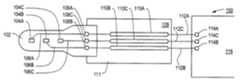
- FIG. 1depicts a top view of a combination of an electrode array module 102 and an LCP substrate based interconnect module 104 .
- the electrode array module 102includes a plurality of electrodes 104 A, 104 B, and 104 C formed on the surface of a substrate 103 .
- Conductors 106 A, 106 B, and 106 Care disposed on the surface of the substrate 103 and are electrically connected to a corresponding electrode.
- the substrate 103 of the electrode array module 102can be silicon or LCP.
- Each of the conductors 106 A- 106 Cis further electrically coupled to a corresponding electrical interconnection bonding pad 108 A- 108 C that is used to provide the signals to a corresponding conductor 110 A- 110 C on an LCP interconnect module 109 .
- the conductors 110 A- 110 Care disposed on the surface of the LCP substrate 111 that forms the LCP interconnect 109 .
- the conductors 110 A- 110 Care coupled at the distal end of the LCP interconnect module 109 to an equipment module 116 via conductors 112 A- 112 C and connectors 114 A, 114 B, and 114 C respectively.
- the equipment modulemay be for example, a percutaneous connector that may include electronic components or circuits, a telemetry module, or other instrumentation.
- FIG. 2depicts a side cross-sectional view of the combination of the electrode array module 102 and the LCP substrate based interconnect 104 .
- the electrode array module 102includes the electrode 104 formed on a substrate 103 and connected to a conductor 106 that is also formed on the surface of the LCP substrate 103 .
- a portion of the electrode 104 and the conductor 106are encapsulated by a coating 202 that is disposed on and chemically bonded to the surface of LCP substrate 103 .
- the conductorsare protected from the external environment that can include the interior of a body after being implanted therein.
- the encapsulantis LCP, while in another embodiment, the encapsulant is silicone.
- the encapsulantcan be coated using a variety of coating methods such as by plasma deposition, by brush, dip, spray, or spin coating from a liquid silicone rubber (LSR) mixture.
- LSRliquid silicone rubber
- the LSRwould preferably be a platinum catalyzed material that is a room temperature vulcanizable (RTV) LSR.
- RTVroom temperature vulcanizable
- a peroxide or tin catalyzed LSRcan also be used.
- the conductor 106is coupled to the corresponding electrical interconnection bonding pad 108 , and via conductor 204 to the corresponding conductor 106 that is formed on the LCP substrate based interconnect module 109 .
- the conductor 110is disposed on the surface of LCP substrate 111 that forms the LCP interconnect module 109 .
- the LCP electrode module 102is affixed to the top surface of the LCP interconnect module 109 .
- the conductor 110is encapsulated by a coating 202 that is disposed on and chemically bonded to the surface of LCP substrate 111 . In this way, the conductors 110 are protected from the external environment that can include the interior of a body after being implanted therein.
- the encapsulantis silicone, while in another embodiment, the encapsulant is an LCP.
- FIG. 3depicts a front cross-sectional view of the LCP substrate based interconnect module 109 .
- the three conductors 110 A- 110 Care disposed on the surface of the LCP substrate 111 and encapsulated by encapsulant 206 as described above.
- the number of electrodes and conductorsare shown for illustrative purposes only. Any number of electrodes and conductors can be formed and the actual number is dependent upon the application requirements.
- the LCP electrode module 102 and the interconnect module 109can be formed into arbitrary shapes. The actual shape that is used will be dependent upon the application requirements.
- FIG. 4depicts an integral electrode array and interconnect module using an LCP substrate.
- a single piece of LCP substrate 401is used to form an electrode array portion 402 and an interconnect portion 403 .
- the electrode array portion 402can include one or more electrode shafts 404 A- 404 D, each of which contains one or more electrodes 406 A- 406 D respectively.
- Each electrodeis coupled to one or more conductors 408 A- 40 D respectively, that are provided to couple electrical signals to and from the respective electrode.
- the number of electrodes on each shaft 404 A- 404 Dis arbitrary and can be adjusted to any predetermined number according to the application requirements.
- N 1 electrodes on shaft 404 Aeach coupled to a corresponding one of N 1 conductors contained in conductor 408 A.
- N 2 electrodes on shaft 404 Beach coupled to a corresponding one of N 2 conductors contained in conductor 408 B.
- N 3 electrodes on shaft 404 Ceach coupled to a corresponding one of N 3 conductors contained in conductor 408 C and, N 4 electrodes on shaft 404 D each coupled to a corresponding one of N 4 conductors contained in conductor 408 D.
- FIG. 5depicts a cross-sectional view of the electrode module 400 of FIG. 4 taken along line B-B′ in FIG. 4 .
- Each of the shafts 404 A- 404 Dare depicted in cross-section and illustrate that each electrode 406 A- 406 D is formed on the surface of the LCP substrate 508 and includes a portion 502 A- 502 D that is not encapsulated by encapsulant 504 A- 504 D and 506 A- 506 D.
- FIG. 6depicts a cross-sectional view of the electrode module 400 taken along C-C′ in FIG. 4 .
- Each of the conductors 408 A- 408 Dare disposed on the surface of the LCP substrate 508 and are encapsulated by encapsulant 602 .
- the conductors 408 A- 408 Dare encapsulated by a coating 602 that is disposed on and chemically bonded to the surface of LCP substrate 508 .
- the encapsulantprotects the conductors 408 A- 408 D from the external environment that can include the interior of a body after being implanted therein.
- the encapsulantis LCP, and in another embodiment, the encapsulant is silicone.
- FIG. 7depicts an integral electrode array, interconnect module, hybrid electronic circuit, and output portion using an LCP substrate.
- an LCP substrate 701is used as the substrate for an electrode array portion 702 , an interconnect portion 704 , a hybrid electronic circuit portion 706 , and an output portion 708 .
- the electrode array portion 702can include one or more electrode shafts 710 A- 710 D, each of which contains one or more electrodes 712 A- 712 D respectively. Each electrode is coupled to one or more conductors 714 A- 714 D respectively, that are provided to couple electrical signals to and from the respective electrode.
- the number of electrodes on each shaft 704 A- 704 Dis arbitrary and can be adjusted to any predetermined number according to the application requirements.
- N 1 electrodes on shaft 710 Aeach coupled to a corresponding one of N 1 conductors contained in conductor 714 A.
- N 2 electrodes on shaft 710 Beach coupled to a corresponding one of N 2 conductors contained in conductor 714 B.
- N 3 electrodes on shaft 710 Ceach coupled to a corresponding one of N 3 conductors contained in conductor 714 C and, N 4 electrodes on shaft 710 D each coupled to a corresponding one of N 4 conductors contained in conductor 714 D. At least some of the conductors 74 A- 714 D are electrically coupled to the hybrid circuit 716 .
- the hybrid circuit 716is electrically can be coupled to one or more output conductors 718 that are coupled to an equipment module 720 .
- the equipment module 720may be for example, a percutaneous connector that may include other electronic components or circuits, a telemetry module, or other instrumentation.
- the hybrid circuitcan be used to provide signal conditioning and processing of signals received from one or more of the electrodes in the electrode array or prior to providing the signal to the equipment module.
- the hybrid circuit 716can also be used to provide signal conditioning, amplification, or processing of signals to be transmitted from the equipment module 720 to one or more of the electrodes as a stimulation signal.
- the hybrid circuit 716 , the conductors 714 A- 714 D and 718 , and a portion of each of the electrodes 712 A- 712 Dare encapsulated by an encapsulation material that is chemically bonded to the LCP substrate.
- the encapsulant materialis silicone and in another embodiment the encapsulant material is LCP.
- the hybrid circuitcan be external to the integral electrode array and interconnect module.
- the hybrid circuitis encapsulated and is connected via encapsulated conductors electrically connected to the interconnect portion of the integral LCP substrate.
- the hybrid circuitthen provides encapsulated conductors to the equipment module that is discussed above with respect to FIG. 7 .
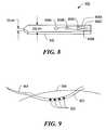
- FIG. 8depicts a micro-wire electrode array using an LCP substrate.
- the micro-wire electrode 800includes a LCP substrate 802 that is approximately 25 micrometers thick and approximately 100 micrometers wide. At least one electrode, and more commonly a plurality of electrodes 804 A, 804 B, and 804 C are disposed on the surface of the LCP substrate 802 . Each electrode 804 A- 804 C is electrically connected to a corresponding electrical interconnect conductor 806 A, 806 B, and 806 C respectively.
- FIG. 9depicts a micro-wire electrode array 902 having electrodes 903 as described above attached to a surgical needle 904 and being inserted into and threaded internal cortical structures 906 using the surgical needle 904 .
- the micro-wire electrode arrayis attached to the surgical needle 904 and inserted into the cortical tissue to a predetermined depth corresponding to an appropriate layer of the cortical tissue, for example layer 4 , in order to receive signals from the surrounding cortical tissue or to stimulate the surrounding cortical tissue.
- the shaftstypically are 10-40 ⁇ m thick and 40-200 ⁇ m wide and a few millimeters when used for sensing or stimulating cortical cells and several centimeters long when used for sensing or stimulating deeper brain/spinal cord structures.
- the spacing between the shaftsis typically between 100-200 ⁇ m.
- electrode contactsare 10-1000 ⁇ m 2 , but will be bigger when the contacts are used to stimulate larger groups of neurons or other bodily structures.
- the spacing between electrodesis typically greater than or equal to 50 ⁇ m, although some protocols require very closely spaced electrodes having a edge to edge distance between adjacent electrodes of as little as 10 ⁇ m.
- the LCP substrateis micro-machined to receive conductor traces.
- the micro-machiningtypically uses one of two known methods.
- the first methodthe “lift-off” method, involves pre-coating the substrate with photoresist and patterning the photoresist in desired conductor traces using standard masking and exposure techniques to expose the LCP substrate where the conductor traces are desired. Unwanted metal is then “lifted off” by dissolving the remaining photoresist using a solvent, leaving the remaining conductor material in the desired configuration.
- the second techniqueis to deposit metal over the entire surface of the LCP substrate, and pattern the metal using standard photoresist, masking, and exposure techniques. The unwanted metal is then etched away using a variety of standard techniques, leaving the remaining conductor in the desired configuration.
- the conductor materialcan be deposited on the patterned surface of the LCP substrate by any of several known methods of deposition such as electroplating, evaporating, sputtering, or other deposit techniques known in the art.
- contact holes for bonding or electrode contactscan be etched into the surface or laser ablation and coated with appropriate conductive materials.
Landscapes
- Health & Medical Sciences (AREA)
- Cardiology (AREA)
- Heart & Thoracic Surgery (AREA)
- Engineering & Computer Science (AREA)
- Biomedical Technology (AREA)
- Nuclear Medicine, Radiotherapy & Molecular Imaging (AREA)
- Radiology & Medical Imaging (AREA)
- Life Sciences & Earth Sciences (AREA)
- Animal Behavior & Ethology (AREA)
- General Health & Medical Sciences (AREA)
- Public Health (AREA)
- Veterinary Medicine (AREA)
- Neurology (AREA)
- Neurosurgery (AREA)
- Orthopedic Medicine & Surgery (AREA)
- Electrotherapy Devices (AREA)
- Combinations Of Printed Boards (AREA)
Abstract
Description

Claims (58)
Priority Applications (1)
| Application Number | Priority Date | Filing Date | Title |
|---|---|---|---|
| US10/158,510US6643552B2 (en) | 2001-05-30 | 2002-05-30 | Implantable devices having a liquid crystal polymer substrate |
Applications Claiming Priority (2)
| Application Number | Priority Date | Filing Date | Title |
|---|---|---|---|
| US29434801P | 2001-05-30 | 2001-05-30 | |
| US10/158,510US6643552B2 (en) | 2001-05-30 | 2002-05-30 | Implantable devices having a liquid crystal polymer substrate |
Publications (2)
| Publication Number | Publication Date |
|---|---|
| US20020198582A1 US20020198582A1 (en) | 2002-12-26 |
| US6643552B2true US6643552B2 (en) | 2003-11-04 |
Family
ID=23133021
Family Applications (1)
| Application Number | Title | Priority Date | Filing Date |
|---|---|---|---|
| US10/158,510Expired - Fee RelatedUS6643552B2 (en) | 2001-05-30 | 2002-05-30 | Implantable devices having a liquid crystal polymer substrate |
Country Status (5)
| Country | Link |
|---|---|
| US (1) | US6643552B2 (en) |
| EP (1) | EP1401513A4 (en) |
| AU (1) | AU2002257344B2 (en) |
| CA (1) | CA2448912C (en) |
| WO (1) | WO2002096482A2 (en) |
Cited By (70)
| Publication number | Priority date | Publication date | Assignee | Title |
|---|---|---|---|---|
| EP1612477A2 (en) | 2004-07-02 | 2006-01-04 | Discus Dental Impressions Inc. | Illumination system for dentistry applications |
| WO2006014370A2 (en) | 2004-07-02 | 2006-02-09 | Discus Dental Impressions, Inc. | Light guide for dentistry applications |
| WO2006034281A1 (en) | 2004-09-21 | 2006-03-30 | Discus Dental Impressions | Dental instruments having durable coatings |
| US20060149319A1 (en)* | 2004-12-30 | 2006-07-06 | Industrial Technology Research Institute | Flexible implantable electrical stimulator array |
| US20060247754A1 (en)* | 2005-04-28 | 2006-11-02 | Robert Greenberg | Flexible circuit electrode array |
| US20070002927A1 (en)* | 2005-06-30 | 2007-01-04 | Intel Corporation | Liquid crystal polymer optical filter carrier |
| WO2007130748A1 (en) | 2006-05-03 | 2007-11-15 | Discus Dental Impressions, Inc. | Dental instruments having anti-microbial coating |
| US20080033500A1 (en)* | 2006-06-22 | 2008-02-07 | Ndi Medical, Llc | Implantable medical devices having a liquid crystal polymer housing |
| US20080140156A1 (en)* | 2002-12-18 | 2008-06-12 | Manuel Manrique Rodriguez | Electrode-Bearing Guide, Cochlear Implant Comprising Said Guide and Production Method Thereof |
| US7761167B2 (en) | 2004-06-10 | 2010-07-20 | Medtronic Urinary Solutions, Inc. | Systems and methods for clinician control of stimulation systems |
| US7813809B2 (en) | 2004-06-10 | 2010-10-12 | Medtronic, Inc. | Implantable pulse generator for providing functional and/or therapeutic stimulation of muscles and/or nerves and/or central nervous system tissue |
| US20100261775A1 (en)* | 2006-07-03 | 2010-10-14 | Sujoy Biswas | Polymorphic form of duloxetine hydrochloride |
| US7926940B2 (en) | 2007-02-23 | 2011-04-19 | Pixeloptics, Inc. | Advanced electro-active optic device |
| US20110237921A1 (en)* | 2009-09-23 | 2011-09-29 | Ripple Llc | Systems and methods for flexible electrodes |
| WO2011143454A1 (en) | 2010-05-12 | 2011-11-17 | Discus Dental, Llc | Dental light device with identification means |
| WO2011160102A2 (en) | 2010-06-19 | 2011-12-22 | Perimetrics, Llc | System and method for determining structural characteristics of an object |
| US8165692B2 (en) | 2004-06-10 | 2012-04-24 | Medtronic Urinary Solutions, Inc. | Implantable pulse generator power management |
| US8195304B2 (en) | 2004-06-10 | 2012-06-05 | Medtronic Urinary Solutions, Inc. | Implantable systems and methods for acquisition and processing of electrical signals |
| US8215770B2 (en) | 2007-02-23 | 2012-07-10 | E-A Ophthalmics | Ophthalmic dynamic aperture |
| US20120209365A1 (en)* | 2011-02-10 | 2012-08-16 | Medtronic, Inc. | Magnetic resonance imaging compatible medical electrical lead and method of making the same |
| US8250745B1 (en) | 2008-01-24 | 2012-08-28 | Advanced Bionics, Llc | Process for manufacturing a microcircuit cochlear electrode array |
| US8332052B1 (en) | 2010-03-18 | 2012-12-11 | Advanced Bionics | Microcircuit cochlear electrode array and method of manufacture |
| EP2537463A1 (en)* | 2011-06-24 | 2012-12-26 | BIOTRONIK SE & Co. KG | Medical Sensor System |
| US8467875B2 (en) | 2004-02-12 | 2013-06-18 | Medtronic, Inc. | Stimulation of dorsal genital nerves to treat urologic dysfunctions |
| US8574164B2 (en) | 2009-10-20 | 2013-11-05 | Nyxoah SA | Apparatus and method for detecting a sleep disordered breathing precursor |
| US8774937B2 (en) | 2009-12-01 | 2014-07-08 | Ecole Polytechnique Federale De Lausanne | Microfabricated surface neurostimulation device and methods of making and using the same |
| US8778022B2 (en) | 2004-11-02 | 2014-07-15 | E-Vision Smart Optics Inc. | Electro-active intraocular lenses |
| US8788064B2 (en) | 2008-11-12 | 2014-07-22 | Ecole Polytechnique Federale De Lausanne | Microfabricated neurostimulation device |
| US8788042B2 (en) | 2008-07-30 | 2014-07-22 | Ecole Polytechnique Federale De Lausanne (Epfl) | Apparatus and method for optimized stimulation of a neurological target |
| US8915588B2 (en) | 2004-11-02 | 2014-12-23 | E-Vision Smart Optics, Inc. | Eyewear including a heads up display |
| US9074070B2 (en) | 2011-10-31 | 2015-07-07 | Ticona Llc | Thermoplastic composition for use in forming a laser direct structured substrate |
| US9122083B2 (en) | 2005-10-28 | 2015-09-01 | E-Vision Smart Optics, Inc. | Eyewear docking station and electronic module |
| US20150265835A1 (en)* | 2012-10-16 | 2015-09-24 | Sapiens Steering Brain Stimulation B.V. | Probe, especially a probe for neural applications |
| US9155614B2 (en) | 2007-01-22 | 2015-10-13 | E-Vision Smart Optics, Inc. | Flexible dynamic electro-active lens |
| US9168384B2 (en) | 2011-05-23 | 2015-10-27 | Medtronic, Inc. | Electrode structure for implantable medical device |
| US9205255B2 (en) | 2004-06-10 | 2015-12-08 | Medtronic Urinary Solutions, Inc. | Implantable pulse generator systems and methods for providing functional and/or therapeutic stimulation of muscles and/or nerves and/or central nervous system tissue |
| US9308382B2 (en) | 2004-06-10 | 2016-04-12 | Medtronic Urinary Solutions, Inc. | Implantable pulse generator systems and methods for providing functional and/or therapeutic stimulation of muscles and/or nerves and/or central nervous system tissue |
| US9403011B2 (en) | 2014-08-27 | 2016-08-02 | Aleva Neurotherapeutics | Leadless neurostimulator |
| US9409013B2 (en) | 2009-10-20 | 2016-08-09 | Nyxoah SA | Method for controlling energy delivery as a function of degree of coupling |
| US9415216B2 (en) | 2009-10-20 | 2016-08-16 | Nyxoah SA | Devices for treatment of sleep apnea |
| US9474894B2 (en) | 2014-08-27 | 2016-10-25 | Aleva Neurotherapeutics | Deep brain stimulation lead |
| US9480846B2 (en) | 2006-05-17 | 2016-11-01 | Medtronic Urinary Solutions, Inc. | Systems and methods for patient control of stimulation systems |
| US9549708B2 (en) | 2010-04-01 | 2017-01-24 | Ecole Polytechnique Federale De Lausanne | Device for interacting with neurological tissue and methods of making and using the same |
| WO2017105531A1 (en) | 2015-12-16 | 2017-06-22 | Airdex Corporation | Load bearing structure |
| US9801709B2 (en) | 2004-11-02 | 2017-10-31 | E-Vision Smart Optics, Inc. | Electro-active intraocular lenses |
| US9869606B2 (en) | 2011-06-18 | 2018-01-16 | Perimetrics, Llc | System and method for determining structural characteristics of an object |
| US9925376B2 (en) | 2014-08-27 | 2018-03-27 | Aleva Neurotherapeutics | Treatment of autoimmune diseases with deep brain stimulation |
| US10195429B1 (en) | 2017-08-02 | 2019-02-05 | Lungpacer Medical Inc. | Systems and methods for intravascular catheter positioning and/or nerve stimulation |
| US10293164B2 (en) | 2017-05-26 | 2019-05-21 | Lungpacer Medical Inc. | Apparatus and methods for assisted breathing by transvascular nerve stimulation |
| EP3505900A1 (en) | 2011-12-16 | 2019-07-03 | Perimetrics, LLC | System for determining structural characteristics of an object |
| US10391314B2 (en) | 2014-01-21 | 2019-08-27 | Lungpacer Medical Inc. | Systems and related methods for optimization of multi-electrode nerve pacing |
| US10406367B2 (en) | 2012-06-21 | 2019-09-10 | Lungpacer Medical Inc. | Transvascular diaphragm pacing system and methods of use |
| US20190331573A1 (en)* | 2016-12-30 | 2019-10-31 | Perimetrics, Llc | System and method for determining structural characteristics of an object |
| US10512772B2 (en) | 2012-03-05 | 2019-12-24 | Lungpacer Medical Inc. | Transvascular nerve stimulation apparatus and methods |
| US10561843B2 (en) | 2007-01-29 | 2020-02-18 | Lungpacer Medical, Inc. | Transvascular nerve stimulation apparatus and methods |
| US10729564B2 (en) | 2018-01-12 | 2020-08-04 | Ripple Llc | Sensor system |
| EP3693286A1 (en) | 2014-06-25 | 2020-08-12 | Lesweek Pty Ltd | Load bearing structure |
| WO2021003200A1 (en) | 2019-06-30 | 2021-01-07 | Perimetrics, Llc | Determination of structural characteristics of an object |
| US10940308B2 (en) | 2017-08-04 | 2021-03-09 | Lungpacer Medical Inc. | Systems and methods for trans-esophageal sympathetic ganglion recruitment |
| US10966620B2 (en) | 2014-05-16 | 2021-04-06 | Aleva Neurotherapeutics Sa | Device for interacting with neurological tissue and methods of making and using the same |
| US10987511B2 (en) | 2018-11-08 | 2021-04-27 | Lungpacer Medical Inc. | Stimulation systems and related user interfaces |
| US11266830B2 (en) | 2018-03-02 | 2022-03-08 | Aleva Neurotherapeutics | Neurostimulation device |
| US11311718B2 (en) | 2014-05-16 | 2022-04-26 | Aleva Neurotherapeutics Sa | Device for interacting with neurological tissue and methods of making and using the same |
| US11357979B2 (en) | 2019-05-16 | 2022-06-14 | Lungpacer Medical Inc. | Systems and methods for sensing and stimulation |
| US11707619B2 (en) | 2013-11-22 | 2023-07-25 | Lungpacer Medical Inc. | Apparatus and methods for assisted breathing by transvascular nerve stimulation |
| US11771900B2 (en) | 2019-06-12 | 2023-10-03 | Lungpacer Medical Inc. | Circuitry for medical stimulation systems |
| US11883658B2 (en) | 2017-06-30 | 2024-01-30 | Lungpacer Medical Inc. | Devices and methods for prevention, moderation, and/or treatment of cognitive injury |
| EP4354112A2 (en) | 2017-12-30 | 2024-04-17 | Perimetrics, Inc. | Determination of structural characteristics of an object |
| US12029903B2 (en) | 2017-12-11 | 2024-07-09 | Lungpacer Medical Inc. | Systems and methods for strengthening a respiratory muscle |
| US12428543B2 (en) | 2021-05-18 | 2025-09-30 | Ticona Llc | Connected medical device containing a liquid crystalline polymer composition having a low dielectric constant |
Families Citing this family (40)
| Publication number | Priority date | Publication date | Assignee | Title |
|---|---|---|---|---|
| US6973342B1 (en)* | 2000-03-02 | 2005-12-06 | Advanced Neuromodulation Systems, Inc. | Flexible bio-probe assembly |
| US7645262B2 (en)* | 2002-04-11 | 2010-01-12 | Second Sight Medical Products, Inc. | Biocompatible bonding method and electronics package suitable for implantation |
| US7917228B2 (en)* | 2003-05-13 | 2011-03-29 | Medtronic, Inc. | Medical lead adaptor assembly |
| WO2005039696A1 (en) | 2003-10-21 | 2005-05-06 | The Regents Of The University Of Michigan | Intracranial neural interface system |
| US8831739B2 (en)* | 2005-06-02 | 2014-09-09 | Huntington Medical Research Institutes | Microelectrode array for chronic deep-brain microstimulation for recording |
| WO2006138358A2 (en) | 2005-06-14 | 2006-12-28 | The Regents Of The University Of Michigan Technology Management Office | Flexible polymer microelectrode with fluid delivery capability and methods for making same |
| WO2007042999A2 (en)* | 2005-10-07 | 2007-04-19 | Neuronexus Technologies | Modular multichannel microelectrode array and methods of making same |
| US20070138405A1 (en)* | 2005-12-16 | 2007-06-21 | 3M Innovative Properties Company | Corona etching |
| WO2007089738A2 (en) | 2006-01-26 | 2007-08-09 | The Regents Of The University Of Michigan | Microelectrode with laterally extending platform for reduction of tissue encapsulation |
| US7853303B2 (en)* | 2006-11-16 | 2010-12-14 | National Research Council Of Canada | Neurological probe and method of using same |
| US8731673B2 (en) | 2007-02-26 | 2014-05-20 | Sapiens Steering Brain Stimulation B.V. | Neural interface system |
| WO2009052425A1 (en) | 2007-10-17 | 2009-04-23 | Neuronexus Technologies | Implantable device including a resorbable carrier |
| US8224417B2 (en) | 2007-10-17 | 2012-07-17 | Neuronexus Technologies, Inc. | Guide tube for an implantable device system |
| US8498720B2 (en) | 2008-02-29 | 2013-07-30 | Neuronexus Technologies, Inc. | Implantable electrode and method of making the same |
| US9289142B2 (en) | 2008-03-24 | 2016-03-22 | Neuronexus Technologies, Inc. | Implantable electrode lead system with a three dimensional arrangement and method of making the same |
| KR101088806B1 (en)* | 2009-01-07 | 2011-12-01 | 주식회사 뉴로바이오시스 | Microelectrode array package using liquid crystal polymer and manufacturing method thereof |
| CN102686147B (en) | 2009-11-05 | 2016-01-20 | 格雷特巴奇有限公司 | waveguide neural interface device |
| EA022775B1 (en)* | 2010-08-25 | 2016-02-29 | Неуронано Аб | Displacement resistant microelectrode, microelectrode bundle and microelectrode array for implantation into soft tissue of a person or animal |
| US9155861B2 (en) | 2010-09-20 | 2015-10-13 | Neuronexus Technologies, Inc. | Neural drug delivery system with fluidic threads |
| US20120300421A1 (en)* | 2011-05-23 | 2012-11-29 | Medtronic, Inc. | Electrical feedthrough for implantable medical device |
| EP2736587B1 (en)* | 2011-07-25 | 2018-10-03 | NeuroNexus Technologies, Inc. | Neural device with modular electrode array |
| EP2877239B1 (en)* | 2012-07-26 | 2023-06-21 | Nyxoah SA | Electrical contacts on a medical device patch |
| WO2014089392A1 (en)* | 2012-12-07 | 2014-06-12 | Medtronic, Inc. | Minimally invasive implantable neurostimulation system |
| CA2898196A1 (en)* | 2013-01-15 | 2014-07-24 | Transient Electronics, Inc. | Implantable transient nerve stimulation device |
| US20140276793A1 (en)* | 2013-03-12 | 2014-09-18 | Medtronic Advanced Energy Llc | Handpiece for an ablation device having tool piece with multiple orientations and method for reconfiguring handpiece |
| KR101654801B1 (en) | 2014-08-08 | 2016-09-07 | 서울대학교산학협력단 | Microelectrode array and package for liquid crystal polymer based neuroprostheses and manufacturing method thereof |
| CN109195516A (en)* | 2016-05-27 | 2019-01-11 | 托多克有限公司 | Organism transplantation type equipment and its manufacturing method |
| CA3041999A1 (en) | 2016-10-31 | 2018-05-03 | The Alfred E. Mann Foundation For Scientific Research | Nerve cuff electrodes fabricated using over-molded lcp substrates |
| CN110267704B (en) | 2016-11-07 | 2023-10-27 | 微导股份有限公司 | Multi-electrode array with integrated body |
| EP3856326B1 (en)* | 2018-09-27 | 2024-10-30 | Verily Life Sciences LLC | Implantable medical devices with microfabricated leads |
| US11395924B2 (en) | 2019-01-07 | 2022-07-26 | Micro-Leads, Inc. | Implantable devices with welded multi-contact electrodes and continuous conductive elements |
| US11318319B2 (en) | 2019-12-04 | 2022-05-03 | Salvia Bioelectronics B.V. | Implantable stimulator with a conformable foil-like electrode array |
| CN114760912B (en)* | 2019-12-04 | 2025-07-04 | 丹参生物电子私人有限责任公司 | Implantable stimulator with electrode array and conformable substrate |
| NL2025268B1 (en)* | 2020-04-03 | 2021-10-25 | Salvia Bioelectronics | An implantable electrical device comprising a substrate, encapsulation layer and adhesion layer |
| US11129986B2 (en) | 2019-12-04 | 2021-09-28 | Salvia Bioelectronics B.V. | Implantable stimulator with a conformable foil like electrode array |
| CA3193733A1 (en) | 2020-09-02 | 2022-03-10 | The Alfred E. Mann Foundation For Scientific Research | Electrode leads having multi-application nerve cuffs and associated systems and methods |
| US20220212018A1 (en)* | 2021-01-04 | 2022-07-07 | Medtronic, Inc. | Temperature sensing of implanted wireless recharge coil |
| AU2022249112A1 (en) | 2021-03-30 | 2023-10-12 | The Alfred E. Mann Foundation For Scientific Research | Electrode leads having nerve cuffs and associated systems |
| EP4366818A1 (en) | 2021-07-09 | 2024-05-15 | The Alfred E. Mann Foundation for Scientific Research | Electrode leads having multi-application helical nerve cuffs and associated systems and methods |
| US12296172B2 (en) | 2022-02-01 | 2025-05-13 | The Alfred E. Mann Foundation For Scientific Research | Electrode leads having nerve contact elements with coil contacts and associated systems and methods |
Citations (3)
| Publication number | Priority date | Publication date | Assignee | Title |
|---|---|---|---|---|
| US5063081A (en)* | 1988-11-14 | 1991-11-05 | I-Stat Corporation | Method of manufacturing a plurality of uniform microfabricated sensing devices having an immobilized ligand receptor |
| US5169397A (en)* | 1990-02-08 | 1992-12-08 | Olympus Optical Co., Ltd. | Medical instrument |
| US6463334B1 (en)* | 1998-11-02 | 2002-10-08 | Cardiac Pacemakers, Inc. | Extendable and retractable lead |
Family Cites Families (9)
| Publication number | Priority date | Publication date | Assignee | Title |
|---|---|---|---|---|
| US3724467A (en)* | 1971-04-23 | 1973-04-03 | Avery Labor Inc | Electrode implant for the neuro-stimulation of the spinal cord |
| US4541440A (en)* | 1984-11-14 | 1985-09-17 | Cordis Corporation | Bipolar epicardial temporary pacing lead |
| US4969468A (en)* | 1986-06-17 | 1990-11-13 | Alfred E. Mann Foundation For Scientific Research | Electrode array for use in connection with a living body and method of manufacture |
| US5273535A (en)* | 1991-11-08 | 1993-12-28 | Ep Technologies, Inc. | Catheter with electrode tip having asymmetric left and right curve configurations |
| US5524338A (en)* | 1991-10-22 | 1996-06-11 | Pi Medical Corporation | Method of making implantable microelectrode |
| US5324322A (en)* | 1992-04-20 | 1994-06-28 | Case Western Reserve University | Thin film implantable electrode and method of manufacture |
| EP0928212B1 (en)* | 1994-07-13 | 2002-10-02 | Fraunhofer-Gesellschaft zur Förderung der angewandten Forschung e.V. | Flexible artificial nerve plate |
| CA2384866C (en)* | 1999-09-28 | 2012-07-10 | Stuart D. Edwards | Treatment of tissue by application of energy and drugs |
| US6829498B2 (en)* | 2000-03-29 | 2004-12-07 | Arizona Board Of Regents | Device for creating a neural interface and method for making same |
- 2002
- 2002-05-30CACA2448912Apatent/CA2448912C/ennot_activeExpired - Fee Related
- 2002-05-30WOPCT/US2002/016942patent/WO2002096482A2/ennot_activeApplication Discontinuation
- 2002-05-30USUS10/158,510patent/US6643552B2/ennot_activeExpired - Fee Related
- 2002-05-30EPEP02726948Apatent/EP1401513A4/ennot_activeWithdrawn
- 2002-05-30AUAU2002257344Apatent/AU2002257344B2/ennot_activeCeased
Patent Citations (3)
| Publication number | Priority date | Publication date | Assignee | Title |
|---|---|---|---|---|
| US5063081A (en)* | 1988-11-14 | 1991-11-05 | I-Stat Corporation | Method of manufacturing a plurality of uniform microfabricated sensing devices having an immobilized ligand receptor |
| US5169397A (en)* | 1990-02-08 | 1992-12-08 | Olympus Optical Co., Ltd. | Medical instrument |
| US6463334B1 (en)* | 1998-11-02 | 2002-10-08 | Cardiac Pacemakers, Inc. | Extendable and retractable lead |
Cited By (191)
| Publication number | Priority date | Publication date | Assignee | Title |
|---|---|---|---|---|
| US20080140156A1 (en)* | 2002-12-18 | 2008-06-12 | Manuel Manrique Rodriguez | Electrode-Bearing Guide, Cochlear Implant Comprising Said Guide and Production Method Thereof |
| US8165697B2 (en)* | 2002-12-18 | 2012-04-24 | Instituto Cientifico Y Tecnologico De Navarra, S.A. | Electrode-bearing guide and cochlear implant |
| US8467875B2 (en) | 2004-02-12 | 2013-06-18 | Medtronic, Inc. | Stimulation of dorsal genital nerves to treat urologic dysfunctions |
| US9216294B2 (en) | 2004-06-10 | 2015-12-22 | Medtronic Urinary Solutions, Inc. | Systems and methods for clinician control of stimulation systems |
| US9308382B2 (en) | 2004-06-10 | 2016-04-12 | Medtronic Urinary Solutions, Inc. | Implantable pulse generator systems and methods for providing functional and/or therapeutic stimulation of muscles and/or nerves and/or central nervous system tissue |
| US10434320B2 (en) | 2004-06-10 | 2019-10-08 | Medtronic Urinary Solutions, Inc. | Implantable pulse generator systems and methods for providing functional and/or therapeutic stimulation of muscles and/or nerves and/or central nervous system tissue |
| US8165692B2 (en) | 2004-06-10 | 2012-04-24 | Medtronic Urinary Solutions, Inc. | Implantable pulse generator power management |
| US8706252B2 (en) | 2004-06-10 | 2014-04-22 | Medtronic, Inc. | Systems and methods for clinician control of stimulation system |
| US10293168B2 (en) | 2004-06-10 | 2019-05-21 | Medtronic Urinary Solutions, Inc. | Systems and methods for clinician control of stimulation systems |
| US9205255B2 (en) | 2004-06-10 | 2015-12-08 | Medtronic Urinary Solutions, Inc. | Implantable pulse generator systems and methods for providing functional and/or therapeutic stimulation of muscles and/or nerves and/or central nervous system tissue |
| US9724526B2 (en) | 2004-06-10 | 2017-08-08 | Medtronic Urinary Solutions, Inc. | Implantable pulse generator systems and methods for operating the same |
| US8195304B2 (en) | 2004-06-10 | 2012-06-05 | Medtronic Urinary Solutions, Inc. | Implantable systems and methods for acquisition and processing of electrical signals |
| US7813809B2 (en) | 2004-06-10 | 2010-10-12 | Medtronic, Inc. | Implantable pulse generator for providing functional and/or therapeutic stimulation of muscles and/or nerves and/or central nervous system tissue |
| US7761167B2 (en) | 2004-06-10 | 2010-07-20 | Medtronic Urinary Solutions, Inc. | Systems and methods for clinician control of stimulation systems |
| WO2006014370A2 (en) | 2004-07-02 | 2006-02-09 | Discus Dental Impressions, Inc. | Light guide for dentistry applications |
| EP3730088A1 (en) | 2004-07-02 | 2020-10-28 | Discus Dental, LLC | Illumination system for dentistry applications |
| EP1614394A2 (en) | 2004-07-02 | 2006-01-11 | Discus Dental Impressions Inc. | Support system for dentistry |
| EP3278763A2 (en) | 2004-07-02 | 2018-02-07 | Discus Dental, LLC | Illumination system for dentistry applications |
| EP1612477A2 (en) | 2004-07-02 | 2006-01-04 | Discus Dental Impressions Inc. | Illumination system for dentistry applications |
| WO2006034281A1 (en) | 2004-09-21 | 2006-03-30 | Discus Dental Impressions | Dental instruments having durable coatings |
| US10092395B2 (en) | 2004-11-02 | 2018-10-09 | E-Vision Smart Optics, Inc. | Electro-active lens with crossed linear electrodes |
| US11262796B2 (en) | 2004-11-02 | 2022-03-01 | E-Vision Smart Optics, Inc. | Eyewear including a detachable power supply and display |
| US8915588B2 (en) | 2004-11-02 | 2014-12-23 | E-Vision Smart Optics, Inc. | Eyewear including a heads up display |
| US8931896B2 (en) | 2004-11-02 | 2015-01-13 | E-Vision Smart Optics Inc. | Eyewear including a docking station |
| US10729539B2 (en) | 2004-11-02 | 2020-08-04 | E-Vision Smart Optics, Inc. | Electro-chromic ophthalmic devices |
| US9124796B2 (en) | 2004-11-02 | 2015-09-01 | E-Vision Smart Optics, Inc. | Eyewear including a remote control camera |
| US10795411B2 (en) | 2004-11-02 | 2020-10-06 | E-Vision Smart Optics, Inc. | Eyewear including a remote control camera and a docking station |
| US8778022B2 (en) | 2004-11-02 | 2014-07-15 | E-Vision Smart Optics Inc. | Electro-active intraocular lenses |
| US10126569B2 (en) | 2004-11-02 | 2018-11-13 | E-Vision Smart Optics Inc. | Flexible electro-active lens |
| US12066695B2 (en) | 2004-11-02 | 2024-08-20 | E-Vision Smart Optics, Inc. | Ophthalmic systems and methods with lateral focus shifting |
| US11822155B2 (en) | 2004-11-02 | 2023-11-21 | E-Vision Smart Optics, Inc. | Eyewear including a remote control camera |
| US10852766B2 (en) | 2004-11-02 | 2020-12-01 | E-Vision Smart Optics, Inc. | Electro-active elements with crossed linear electrodes |
| US10379575B2 (en) | 2004-11-02 | 2019-08-13 | E-Vision Smart Optics, Inc. | Eyewear including a remote control camera and a docking station |
| US10159563B2 (en) | 2004-11-02 | 2018-12-25 | E-Vision Smart Optics, Inc. | Eyewear including a detachable power supply and a display |
| US11144090B2 (en) | 2004-11-02 | 2021-10-12 | E-Vision Smart Optics, Inc. | Eyewear including a camera or display |
| US11422389B2 (en) | 2004-11-02 | 2022-08-23 | E-Vision Smart Optics, Inc. | Eyewear including a remote control camera |
| US10172704B2 (en) | 2004-11-02 | 2019-01-08 | E-Vision Smart Optics, Inc. | Methods and apparatus for actuating an ophthalmic lens in response to ciliary muscle motion |
| US9801709B2 (en) | 2004-11-02 | 2017-10-31 | E-Vision Smart Optics, Inc. | Electro-active intraocular lenses |
| US7447551B2 (en)* | 2004-12-30 | 2008-11-04 | Industrial Technology Research Institute | Flexible implantable electrical stimulator array |
| US20060149319A1 (en)* | 2004-12-30 | 2006-07-06 | Industrial Technology Research Institute | Flexible implantable electrical stimulator array |
| US20060247754A1 (en)* | 2005-04-28 | 2006-11-02 | Robert Greenberg | Flexible circuit electrode array |
| US8014878B2 (en)* | 2005-04-28 | 2011-09-06 | Second Sight Medical Products, Inc. | Flexible circuit electrode array |
| AU2006239178B2 (en)* | 2005-04-28 | 2011-03-03 | Doheny Eye Institute | Flexible circuit electrode array |
| US20070291800A1 (en)* | 2005-06-30 | 2007-12-20 | Intel Corporation | Liquid Crystal Polymer Optical Filter Carrier |
| US7570675B2 (en) | 2005-06-30 | 2009-08-04 | Intel Corporation | Liquid crystal polymer optical filter carrier |
| US7280181B2 (en) | 2005-06-30 | 2007-10-09 | Intel Corporation | Liquid crystal polymer optical filter carrier |
| US20070002927A1 (en)* | 2005-06-30 | 2007-01-04 | Intel Corporation | Liquid crystal polymer optical filter carrier |
| US9122083B2 (en) | 2005-10-28 | 2015-09-01 | E-Vision Smart Optics, Inc. | Eyewear docking station and electronic module |
| US10114235B2 (en) | 2005-10-28 | 2018-10-30 | E-Vision Smart Optics, Inc. | Eyewear docking station and electronic module |
| WO2007130748A1 (en) | 2006-05-03 | 2007-11-15 | Discus Dental Impressions, Inc. | Dental instruments having anti-microbial coating |
| US10322287B2 (en) | 2006-05-17 | 2019-06-18 | Medtronic Urinary Solutions, Inc. | Systems and methods for patient control of stimulation systems |
| US9480846B2 (en) | 2006-05-17 | 2016-11-01 | Medtronic Urinary Solutions, Inc. | Systems and methods for patient control of stimulation systems |
| US8463393B2 (en)* | 2006-06-22 | 2013-06-11 | Medtronic, Inc. | Implantable medical devices having a liquid crystal polymer housing |
| US20080033500A1 (en)* | 2006-06-22 | 2008-02-07 | Ndi Medical, Llc | Implantable medical devices having a liquid crystal polymer housing |
| US20100261775A1 (en)* | 2006-07-03 | 2010-10-14 | Sujoy Biswas | Polymorphic form of duloxetine hydrochloride |
| US12326617B2 (en) | 2007-01-22 | 2025-06-10 | E-Vision Smart Optics, Inc. | Flexible electro-active lens |
| US12235524B2 (en) | 2007-01-22 | 2025-02-25 | E-Vision Smart Optics, Inc. | Flexible electro-active lens |
| US9155614B2 (en) | 2007-01-22 | 2015-10-13 | E-Vision Smart Optics, Inc. | Flexible dynamic electro-active lens |
| US11474380B2 (en) | 2007-01-22 | 2022-10-18 | E-Vision Smart Optics, Inc. | Flexible electro-active lens |
| US10864374B2 (en) | 2007-01-29 | 2020-12-15 | Lungpacer Medical Inc. | Transvascular nerve stimulation apparatus and methods |
| US10765867B2 (en) | 2007-01-29 | 2020-09-08 | Lungpacer Medical Inc. | Transvascular nerve stimulation apparatus and methods |
| US10792499B2 (en) | 2007-01-29 | 2020-10-06 | Lungpacer Medical Inc. | Transvascular nerve stimulation apparatus and methods |
| US11027130B2 (en) | 2007-01-29 | 2021-06-08 | Lungpacer Medical Inc. | Transvascular nerve stimulation apparatus and methods |
| US10561843B2 (en) | 2007-01-29 | 2020-02-18 | Lungpacer Medical, Inc. | Transvascular nerve stimulation apparatus and methods |
| US12268877B2 (en) | 2007-01-29 | 2025-04-08 | Lungpacer Medical Inc. | Transvascular nerve stimulation apparatus and methods |
| US8215770B2 (en) | 2007-02-23 | 2012-07-10 | E-A Ophthalmics | Ophthalmic dynamic aperture |
| US7926940B2 (en) | 2007-02-23 | 2011-04-19 | Pixeloptics, Inc. | Advanced electro-active optic device |
| US8250745B1 (en) | 2008-01-24 | 2012-08-28 | Advanced Bionics, Llc | Process for manufacturing a microcircuit cochlear electrode array |
| US9402991B1 (en) | 2008-01-24 | 2016-08-02 | Advanced Bionics, Llc | Microcircuit cochlear electrode array and method of manufacture |
| US8897894B1 (en) | 2008-01-24 | 2014-11-25 | Advanced Bionics Llc | Microcircuit cochlear electrode array and method of manufacture |
| US9072906B2 (en) | 2008-07-30 | 2015-07-07 | Ecole Polytechnique Federale De Lausanne | Apparatus and method for optimized stimulation of a neurological target |
| US10166392B2 (en) | 2008-07-30 | 2019-01-01 | Ecole Polytechnique Federale De Lausanne | Apparatus and method for optimized stimulation of a neurological target |
| US10952627B2 (en) | 2008-07-30 | 2021-03-23 | Ecole Polytechnique Federale De Lausanne | Apparatus and method for optimized stimulation of a neurological target |
| US8788042B2 (en) | 2008-07-30 | 2014-07-22 | Ecole Polytechnique Federale De Lausanne (Epfl) | Apparatus and method for optimized stimulation of a neurological target |
| US11123548B2 (en) | 2008-11-12 | 2021-09-21 | Ecole Polytechnique Federale De Lausanne | Microfabricated neurostimulation device |
| US9440082B2 (en) | 2008-11-12 | 2016-09-13 | Ecole Polytechnique Federale De Lausanne | Microfabricated neurostimulation device |
| US8788064B2 (en) | 2008-11-12 | 2014-07-22 | Ecole Polytechnique Federale De Lausanne | Microfabricated neurostimulation device |
| US10406350B2 (en) | 2008-11-12 | 2019-09-10 | Ecole Polytechnique Federale De Lausanne | Microfabricated neurostimulation device |
| US20110237921A1 (en)* | 2009-09-23 | 2011-09-29 | Ripple Llc | Systems and methods for flexible electrodes |
| US9061134B2 (en) | 2009-09-23 | 2015-06-23 | Ripple Llc | Systems and methods for flexible electrodes |
| US11273307B2 (en) | 2009-10-20 | 2022-03-15 | Nyxoah SA | Method and device for treating sleep apnea |
| US9943686B2 (en) | 2009-10-20 | 2018-04-17 | Nyxoah SA | Method and device for treating sleep apnea based on tongue movement |
| US9409013B2 (en) | 2009-10-20 | 2016-08-09 | Nyxoah SA | Method for controlling energy delivery as a function of degree of coupling |
| US9415216B2 (en) | 2009-10-20 | 2016-08-16 | Nyxoah SA | Devices for treatment of sleep apnea |
| US9415215B2 (en) | 2009-10-20 | 2016-08-16 | Nyxoah SA | Methods for treatment of sleep apnea |
| US8574164B2 (en) | 2009-10-20 | 2013-11-05 | Nyxoah SA | Apparatus and method for detecting a sleep disordered breathing precursor |
| US9248290B2 (en) | 2009-10-20 | 2016-02-02 | Adi Mashiach | Apparatus and methods for feedback-based nerve modulation |
| US9550064B2 (en) | 2009-10-20 | 2017-01-24 | Adi Mashiach | Apparatus and methods for feedback-based nerve modulation |
| US8577464B2 (en) | 2009-10-20 | 2013-11-05 | Nyxoah SA | Apparatus and methods for feedback-based nerve modulation |
| US8577472B2 (en) | 2009-10-20 | 2013-11-05 | Nyxoah SA | Systems and methods for determining a sleep disorder based on positioning of the tongue |
| US8774937B2 (en) | 2009-12-01 | 2014-07-08 | Ecole Polytechnique Federale De Lausanne | Microfabricated surface neurostimulation device and methods of making and using the same |
| US9604055B2 (en) | 2009-12-01 | 2017-03-28 | Ecole Polytechnique Federale De Lausanne | Microfabricated surface neurostimulation device and methods of making and using the same |
| US9192767B2 (en) | 2009-12-01 | 2015-11-24 | Ecole Polytechnique Federale De Lausanne | Microfabricated surface neurostimulation device and methods of making and using the same |
| US8849426B1 (en) | 2010-03-18 | 2014-09-30 | Advanced Bionics Ag | Microcircuit cochlear electrode array and method of manufacture |
| US8332052B1 (en) | 2010-03-18 | 2012-12-11 | Advanced Bionics | Microcircuit cochlear electrode array and method of manufacture |
| US9549708B2 (en) | 2010-04-01 | 2017-01-24 | Ecole Polytechnique Federale De Lausanne | Device for interacting with neurological tissue and methods of making and using the same |
| US11766560B2 (en) | 2010-04-01 | 2023-09-26 | Ecole Polytechnique Federale De Lausanne | Device for interacting with neurological tissue and methods of making and using the same |
| WO2011143454A1 (en) | 2010-05-12 | 2011-11-17 | Discus Dental, Llc | Dental light device with identification means |
| WO2011160102A2 (en) | 2010-06-19 | 2011-12-22 | Perimetrics, Llc | System and method for determining structural characteristics of an object |
| US9358089B2 (en) | 2010-06-19 | 2016-06-07 | Perimetrics, Llc | System and method for determining structural characteristics of an object |
| EP3235440A1 (en) | 2010-06-19 | 2017-10-25 | Perimetrics, LLC | System and method for determining structural characteristics of an object |
| EP3510940A1 (en) | 2010-06-19 | 2019-07-17 | Perimetrics, LLC | System and method for determining structural characteristics of an object |
| US20120209365A1 (en)* | 2011-02-10 | 2012-08-16 | Medtronic, Inc. | Magnetic resonance imaging compatible medical electrical lead and method of making the same |
| US8612021B2 (en)* | 2011-02-10 | 2013-12-17 | Medtronic, Inc. | Magnetic resonance imaging compatible medical electrical lead and method of making the same |
| US9168384B2 (en) | 2011-05-23 | 2015-10-27 | Medtronic, Inc. | Electrode structure for implantable medical device |
| US9869606B2 (en) | 2011-06-18 | 2018-01-16 | Perimetrics, Llc | System and method for determining structural characteristics of an object |
| US9101277B2 (en) | 2011-06-24 | 2015-08-11 | Biotronik Se & Co. Kg | Medical sensor system |
| EP2537463A1 (en)* | 2011-06-24 | 2012-12-26 | BIOTRONIK SE & Co. KG | Medical Sensor System |
| US8700183B2 (en) | 2011-09-30 | 2014-04-15 | Nyxoah SA | Devices and methods for low current neural modulation |
| US8577478B2 (en) | 2011-09-30 | 2013-11-05 | Nyxoah SA | Antenna providing variable communication with an implant |
| US9314613B2 (en) | 2011-09-30 | 2016-04-19 | Adi Mashiach | Apparatus and methods for modulating nerves using parallel electric fields |
| US9302093B2 (en) | 2011-09-30 | 2016-04-05 | Nyxoah SA | Devices and methods for delivering energy as a function of condition severity |
| US9248291B2 (en) | 2011-09-30 | 2016-02-02 | Adi Mashiach | Hypertension therapy implant apparatus |
| US9649493B2 (en) | 2011-09-30 | 2017-05-16 | Adi Mashiach | System and method for nerve modulation using noncontacting electrodes |
| US8577467B2 (en) | 2011-09-30 | 2013-11-05 | Nyxoah SA | Apparatus and method for controlling energy delivery as a function of degree of coupling |
| US8577466B2 (en) | 2011-09-30 | 2013-11-05 | Nyxoah SA | System and method for nerve modulation using noncontacting electrodes |
| US9403009B2 (en) | 2011-09-30 | 2016-08-02 | Nyxoah SA | Apparatus and methods for implant coupling indication |
| US8588941B2 (en) | 2011-09-30 | 2013-11-19 | Nyxoah SA | Device and method for modulating nerves using parallel electric fields |
| US9044612B2 (en) | 2011-09-30 | 2015-06-02 | Adi Mashiach | Apparatus and method for extending implant life using a dual power scheme |
| US9358392B2 (en) | 2011-09-30 | 2016-06-07 | Adi Mashiach | Electrode configuration for implantable modulator |
| US8644957B2 (en) | 2011-09-30 | 2014-02-04 | Nyxoah SA | Electrode configuration for implantable modulator |
| US8989868B2 (en) | 2011-09-30 | 2015-03-24 | Hyllio SA | Apparatus and method for controlling energy delivery as a function of degree of coupling |
| US8577468B2 (en) | 2011-09-30 | 2013-11-05 | Nyxoah SA | Apparatus and method for extending implant life using a dual power scheme |
| US8718776B2 (en) | 2011-09-30 | 2014-05-06 | Nyxoah SA | Apparatus and method to control an implant |
| US8929999B2 (en) | 2011-09-30 | 2015-01-06 | Adi Maschiach | Electrode configuration for implantable modulator |
| US9878159B2 (en) | 2011-09-30 | 2018-01-30 | Adi Mashiach | Hypertension therapy implant apparatus |
| US9421372B2 (en) | 2011-09-30 | 2016-08-23 | Adi Mashiach | Head pain management device having an antenna |
| US10828492B2 (en) | 2011-09-30 | 2020-11-10 | Adi Mashiach | Devices and methods for low current neural modulation |
| US8798773B2 (en) | 2011-09-30 | 2014-08-05 | Man & Science, SA | Electrode configuration for implantable modulator |
| US9061151B2 (en) | 2011-09-30 | 2015-06-23 | Adi Mashiach | Apparatus and method to control an implant |
| US9895540B2 (en) | 2011-09-30 | 2018-02-20 | Nyxoah SA | Devices and methods for low current neural modulation |
| US8577465B2 (en) | 2011-09-30 | 2013-11-05 | Nyxoah SA | Modulator apparatus configured for implantation |
| US9074070B2 (en) | 2011-10-31 | 2015-07-07 | Ticona Llc | Thermoplastic composition for use in forming a laser direct structured substrate |
| EP3505900A1 (en) | 2011-12-16 | 2019-07-03 | Perimetrics, LLC | System for determining structural characteristics of an object |
| US10598960B2 (en) | 2012-01-06 | 2020-03-24 | E-Vision Smart Optics, Inc. | Eyewear docking station and electronic module |
| US11487138B2 (en) | 2012-01-06 | 2022-11-01 | E-Vision Smart Optics, Inc. | Eyewear docking station and electronic module |
| US12271056B2 (en) | 2012-01-06 | 2025-04-08 | E-Vision Smart Optics, Inc. | Eyewear docking station and electronic module |
| US11971612B2 (en) | 2012-01-06 | 2024-04-30 | E-Vision Smart Optics, Inc. | Eyewear docking station and electronic module |
| US11369787B2 (en) | 2012-03-05 | 2022-06-28 | Lungpacer Medical Inc. | Transvascular nerve stimulation apparatus and methods |
| US10512772B2 (en) | 2012-03-05 | 2019-12-24 | Lungpacer Medical Inc. | Transvascular nerve stimulation apparatus and methods |
| US11357985B2 (en) | 2012-06-21 | 2022-06-14 | Lungpacer Medical Inc. | Transvascular diaphragm pacing systems and methods of use |
| US10406367B2 (en) | 2012-06-21 | 2019-09-10 | Lungpacer Medical Inc. | Transvascular diaphragm pacing system and methods of use |
| US10561844B2 (en) | 2012-06-21 | 2020-02-18 | Lungpacer Medical Inc. | Diaphragm pacing systems and methods of use |
| US10589097B2 (en) | 2012-06-21 | 2020-03-17 | Lungpacer Medical Inc. | Transvascular diaphragm pacing systems and methods of use |
| US9662494B2 (en)* | 2012-10-16 | 2017-05-30 | Medtronic Bakken Research Center B.V. | Probe, especially a probe for neural applications |
| US20150265835A1 (en)* | 2012-10-16 | 2015-09-24 | Sapiens Steering Brain Stimulation B.V. | Probe, especially a probe for neural applications |
| US12239838B2 (en) | 2013-11-22 | 2025-03-04 | Lungpacer Medical Inc. | Apparatus and methods for assisted breathing by transvascular nerve stimulation |
| US11707619B2 (en) | 2013-11-22 | 2023-07-25 | Lungpacer Medical Inc. | Apparatus and methods for assisted breathing by transvascular nerve stimulation |
| US12172020B2 (en) | 2014-01-21 | 2024-12-24 | Lungpacer Medical Inc. | Systems and related methods for optimization of multi-electrode nerve pacing |
| US10391314B2 (en) | 2014-01-21 | 2019-08-27 | Lungpacer Medical Inc. | Systems and related methods for optimization of multi-electrode nerve pacing |
| US11311730B2 (en) | 2014-01-21 | 2022-04-26 | Lungpacer Medical Inc. | Systems and related methods for optimization of multi-electrode nerve pacing |
| US11311718B2 (en) | 2014-05-16 | 2022-04-26 | Aleva Neurotherapeutics Sa | Device for interacting with neurological tissue and methods of making and using the same |
| US10966620B2 (en) | 2014-05-16 | 2021-04-06 | Aleva Neurotherapeutics Sa | Device for interacting with neurological tissue and methods of making and using the same |
| EP3693286A1 (en) | 2014-06-25 | 2020-08-12 | Lesweek Pty Ltd | Load bearing structure |
| US9889304B2 (en) | 2014-08-27 | 2018-02-13 | Aleva Neurotherapeutics | Leadless neurostimulator |
| US11730953B2 (en) | 2014-08-27 | 2023-08-22 | Aleva Neurotherapeutics | Deep brain stimulation lead |
| US11167126B2 (en) | 2014-08-27 | 2021-11-09 | Aleva Neurotherapeutics | Deep brain stimulation lead |
| US10201707B2 (en) | 2014-08-27 | 2019-02-12 | Aleva Neurotherapeutics | Treatment of autoimmune diseases with deep brain stimulation |
| US10065031B2 (en) | 2014-08-27 | 2018-09-04 | Aleva Neurotherapeutics | Deep brain stimulation lead |
| US9403011B2 (en) | 2014-08-27 | 2016-08-02 | Aleva Neurotherapeutics | Leadless neurostimulator |
| US9474894B2 (en) | 2014-08-27 | 2016-10-25 | Aleva Neurotherapeutics | Deep brain stimulation lead |
| US9925376B2 (en) | 2014-08-27 | 2018-03-27 | Aleva Neurotherapeutics | Treatment of autoimmune diseases with deep brain stimulation |
| US9572985B2 (en) | 2014-08-27 | 2017-02-21 | Aleva Neurotherapeutics | Method of manufacturing a thin film leadless neurostimulator |
| US10441779B2 (en) | 2014-08-27 | 2019-10-15 | Aleva Neurotherapeutics | Deep brain stimulation lead |
| WO2017105531A1 (en) | 2015-12-16 | 2017-06-22 | Airdex Corporation | Load bearing structure |
| US11493415B2 (en)* | 2016-12-30 | 2022-11-08 | Perimetrics, Inc. | System and method for determining structural characteristics of an object |
| EP4578406A2 (en) | 2016-12-30 | 2025-07-02 | Perimetrics, Inc. | System and method for determining structural characteristics of an object |
| US20190331573A1 (en)* | 2016-12-30 | 2019-10-31 | Perimetrics, Llc | System and method for determining structural characteristics of an object |
| US10293164B2 (en) | 2017-05-26 | 2019-05-21 | Lungpacer Medical Inc. | Apparatus and methods for assisted breathing by transvascular nerve stimulation |
| US12029901B2 (en) | 2017-06-30 | 2024-07-09 | Lungpacer Medical Inc. | Devices and methods for prevention, moderation, and/or treatment of cognitive injury |
| US11883658B2 (en) | 2017-06-30 | 2024-01-30 | Lungpacer Medical Inc. | Devices and methods for prevention, moderation, and/or treatment of cognitive injury |
| US10926087B2 (en) | 2017-08-02 | 2021-02-23 | Lungpacer Medical Inc. | Systems and methods for intravascular catheter positioning and/or nerve stimulation |
| US10195429B1 (en) | 2017-08-02 | 2019-02-05 | Lungpacer Medical Inc. | Systems and methods for intravascular catheter positioning and/or nerve stimulation |
| US11090489B2 (en) | 2017-08-02 | 2021-08-17 | Lungpacer Medical, Inc. | Systems and methods for intravascular catheter positioning and/or nerve stimulation |
| US12029902B2 (en) | 2017-08-02 | 2024-07-09 | Lungpacer Medical Inc. | Intravascular catheter methods |
| US11944810B2 (en) | 2017-08-04 | 2024-04-02 | Lungpacer Medical Inc. | Systems and methods for trans-esophageal sympathetic ganglion recruitment |
| US10940308B2 (en) | 2017-08-04 | 2021-03-09 | Lungpacer Medical Inc. | Systems and methods for trans-esophageal sympathetic ganglion recruitment |
| US12029903B2 (en) | 2017-12-11 | 2024-07-09 | Lungpacer Medical Inc. | Systems and methods for strengthening a respiratory muscle |
| EP4354112A2 (en) | 2017-12-30 | 2024-04-17 | Perimetrics, Inc. | Determination of structural characteristics of an object |
| US10729564B2 (en) | 2018-01-12 | 2020-08-04 | Ripple Llc | Sensor system |
| US11642232B2 (en) | 2018-01-12 | 2023-05-09 | Ripple Llc | Sensor system |
| US11266830B2 (en) | 2018-03-02 | 2022-03-08 | Aleva Neurotherapeutics | Neurostimulation device |
| US11738192B2 (en) | 2018-03-02 | 2023-08-29 | Aleva Neurotherapeutics | Neurostimulation device |
| US10987511B2 (en) | 2018-11-08 | 2021-04-27 | Lungpacer Medical Inc. | Stimulation systems and related user interfaces |
| US11890462B2 (en) | 2018-11-08 | 2024-02-06 | Lungpacer Medical Inc. | Stimulation systems and related user interfaces |
| US11717673B2 (en) | 2018-11-08 | 2023-08-08 | Lungpacer Medical Inc. | Stimulation systems and related user interfaces |
| US11357979B2 (en) | 2019-05-16 | 2022-06-14 | Lungpacer Medical Inc. | Systems and methods for sensing and stimulation |
| US11771900B2 (en) | 2019-06-12 | 2023-10-03 | Lungpacer Medical Inc. | Circuitry for medical stimulation systems |
| US12403312B2 (en) | 2019-06-12 | 2025-09-02 | Lungpacer Medical Inc. | Circuitry for medical stimulation systems |
| WO2021003200A1 (en) | 2019-06-30 | 2021-01-07 | Perimetrics, Llc | Determination of structural characteristics of an object |
| US12428543B2 (en) | 2021-05-18 | 2025-09-30 | Ticona Llc | Connected medical device containing a liquid crystalline polymer composition having a low dielectric constant |
Also Published As
| Publication number | Publication date |
|---|---|
| CA2448912C (en) | 2012-01-03 |
| EP1401513A2 (en) | 2004-03-31 |
| WO2002096482A3 (en) | 2003-10-16 |
| AU2002257344B2 (en) | 2006-05-25 |
| US20020198582A1 (en) | 2002-12-26 |
| EP1401513A4 (en) | 2007-09-12 |
| CA2448912A1 (en) | 2002-12-05 |
| WO2002096482A2 (en) | 2002-12-05 |
Similar Documents
| Publication | Publication Date | Title |
|---|---|---|
| US6643552B2 (en) | Implantable devices having a liquid crystal polymer substrate | |
| AU2002257344A1 (en) | Implantable devices having a liquid crystal polymer substrate | |
| Lee et al. | Monolithic encapsulation of implantable neuroprosthetic devices using liquid crystal polymers | |
| US7871661B2 (en) | Serpentine and corduroy circuits to enhance the stretchablity of a stretchable electronic device | |
| US7146221B2 (en) | Flexible electrode array for artifical vision | |
| US7912556B2 (en) | Electrode array for even neural pressure | |
| US7035692B1 (en) | High density polymer-based integrated electrode array | |
| AU2008272808B2 (en) | Return electrode for a flexible circuit electrode array | |
| CN106334258B (en) | Stimulating electrode structure of artificial retina and artificial retina | |
| Jeong et al. | Liquid Crystal Polymer(LCP), an Attractive Substrate for Retinal Implant | |
| US20110307042A1 (en) | Electrode arrays based on polyetherketoneketone | |
| US12383751B2 (en) | Self-centering ceramic washer | |
| US20220212016A1 (en) | Connectors For High Density Neural Interfaces | |
| US20220265998A1 (en) | Connectors For High Density Neural Interfaces | |
| CN206198475U (en) | The stimulating electrode structure and artificial retina of artificial retina | |
| US12329963B2 (en) | Anatomically contoured stimulation leads for high density neural interface | |
| Meyer et al. | Chronically implantable neural information transducers | |
| Williams | David F. Williams, Ph. D. |
Legal Events
| Date | Code | Title | Description |
|---|---|---|---|
| AS | Assignment | Owner name:INNERSEA TECHNOLOGY, MASSACHUSETTS Free format text:ASSIGNMENT OF ASSIGNORS INTEREST;ASSIGNOR:EDELL, DAVID J.;REEL/FRAME:013082/0874 Effective date:20020701 | |
| AS | Assignment | Owner name:FOSTER-MILLER, INC., MASSACHUSETTS Free format text:ASSIGNMENT OF ASSIGNORS INTEREST;ASSIGNOR:FARRELL, BRIAN;REEL/FRAME:013137/0473 Effective date:20020719 | |
| CC | Certificate of correction | ||
| FPAY | Fee payment | Year of fee payment:4 | |
| FEPP | Fee payment procedure | Free format text:PAT HOLDER NO LONGER CLAIMS SMALL ENTITY STATUS, ENTITY STATUS SET TO UNDISCOUNTED (ORIGINAL EVENT CODE: STOL); ENTITY STATUS OF PATENT OWNER: LARGE ENTITY | |
| FPAY | Fee payment | Year of fee payment:8 | |
| AS | Assignment | Owner name:QINETIQ NORTH AMERICA, INC., VIRGINIA Free format text:ASSIGNMENT OF ASSIGNORS INTEREST;ASSIGNOR:FOSTER-MILLER, INC.;REEL/FRAME:026881/0994 Effective date:20110909 | |
| AS | Assignment | Owner name:FOSTER-MILLER, INC., MASSACHUSETTS Free format text:ASSIGNMENT OF ASSIGNORS INTEREST;ASSIGNOR:QINETIQ NORTH AMERICA, INC.;REEL/FRAME:032807/0348 Effective date:20140331 | |
| REMI | Maintenance fee reminder mailed | ||
| LAPS | Lapse for failure to pay maintenance fees | ||
| STCH | Information on status: patent discontinuation | Free format text:PATENT EXPIRED DUE TO NONPAYMENT OF MAINTENANCE FEES UNDER 37 CFR 1.362 | |
| FP | Lapsed due to failure to pay maintenance fee | Effective date:20151104 |