US6643070B2 - Viewing tube for an optical device - Google Patents
Viewing tube for an optical deviceDownload PDFInfo
- Publication number
- US6643070B2 US6643070B2US10/080,106US8010602AUS6643070B2US 6643070 B2US6643070 B2US 6643070B2US 8010602 AUS8010602 AUS 8010602AUS 6643070 B2US6643070 B2US 6643070B2
- Authority
- US
- United States
- Prior art keywords
- beam path
- light
- viewing tube
- beam splitter
- splitters
- Prior art date
- Legal status (The legal status is an assumption and is not a legal conclusion. Google has not performed a legal analysis and makes no representation as to the accuracy of the status listed.)
- Expired - Lifetime
Links
- 230000003287optical effectEffects0.000titleclaimsabstractdescription11
- 238000003384imaging methodMethods0.000abstractdescription7
- 238000011161developmentMethods0.000description2
- 230000018109developmental processEffects0.000description2
- 230000001419dependent effectEffects0.000description1
- 238000005286illuminationMethods0.000description1
- 230000007935neutral effectEffects0.000description1
- 230000010287polarizationEffects0.000description1
Images

Classifications
- G—PHYSICS
- G02—OPTICS
- G02B—OPTICAL ELEMENTS, SYSTEMS OR APPARATUS
- G02B21/00—Microscopes
- G02B21/18—Arrangements with more than one light path, e.g. for comparing two specimens
- G02B21/20—Binocular arrangements
- G02B21/22—Stereoscopic arrangements
Definitions
- the inventionrefers to a viewing tube for an optical device and in particular for a microscope.
- beam splitterswhich deflect a portion of the light to a simultaneous observation tube and/or to an imaging or recording unit, for example a photographic camera or a video unit, are provided in the beam path of the viewing tube.
- the beam splitterscan also reflect into the beam path light from a display and/or processing unit, for example a treatment laser and/or target beam laser.
- a display and/or processing unitfor example a treatment laser and/or target beam laser.
- multiple beam splitterseach of which is permanently associated with a specific device or a specific task, are therefore provided in succession in the beam path of the viewing tube. Since often not all of the functions that can be performed with these “cascaded” beam splitters are needed, the beam splitters provided in succession in the beam path result in a light attenuation that is unnecessary in many applications.
- the beam splitteris rotatable about the optical axis of the respective beam path.
- the beam splitterthus deflects a portion of the light of the respective beam path in different directions depending on its rotational position. If the different units desired—such as simultaneous observation tubes, imaging or recording units, display units for presenting images and/or data, and/or units for reflecting light into the beam path of the viewing tube—are then arranged in those different directions, then the various functions desired can be implemented on the basis of the particular rotational position.
- Rotation of the beam splitters introduced into the individual beam pathscan be performed in coupled and/or uncoupled fashion.
- actuation of an adjusting elementcauses both beam splitters to rotate, whereas in uncoupled rotation the beam splitters introduced into the left and right beam paths can be rotated independently of one another.
- the viewing tubehas, in a manner known per se, a binocular beam path.
- a binocular beam pathit is possible, for example, in one rotational position of the beam splitters to reflect light out of the two beam path segments into a binocular simultaneous observation tube, and in another rotational position to reflect light out of one beam path segment onto an imaging or recording unit and to reflect light into the other beam path segment.
- the lightcan be, for example, the light of a display unit or the light of an illumination light source or a processing unit.
- each beam splitterhas two rotational positions; the two rotational positions can easily be defined by stops, so that the respective beam splitter is exactly adjusted in terms of its rotational position.
- beam splitter elementssuch as wavelength-selective splitters, polarization splitters, or neutral splitters, such as semitransparent mirrors, and in particular beam splitter cubes, can of course be used as beam splitters.
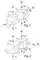
- FIG. 1shows the exemplary embodiment in a first position of the beam splitter cubes
- FIG. 2shows the exemplary embodiment in a second position of the beam splitter cubes.
- FIG. 1shows an exemplary embodiment of the invention in which, with no limitation as to the general applicability of the invention, a respective beam splitter cube 1 and 2 is arranged in the left (L) and right (R) beam path segment of a stereomicroscope (not depicted in further detail).
- Beam splitter cubes 1 and 2are preferably but not necessarily located in the portion of the beam path in which the latter is parallel.
- Light I coming from a microscope objectivepasses through surfaces 11 and 21 into beam splitter cubes 1 and 2 , respectively.
- a portion R*I of the lightis deflected 90 degrees and emerges from surfaces 12 and 22 .
- the continuing light beamhaving an intensity (1 ⁇ R)*I, emerges from surfaces 13 and 23 .
- the possibilities for observation by the observer or observersare depicted schematically.
- beam splitter cubes 1 and 2are arranged in such a way that surfaces 12 and 22 are oriented oppositely to one another. In this position, for example, light can be deflected by beam splitter cube 1 onto an imaging unit. Beam splitter cube 2 can, for example, be used to reflect light onto a specimen slide. Of course it can also be used in a monocular simultaneous observation tube.
- beam splitter cubes 1 and 2are arranged in such a way that surfaces 12 and 22 , from which the reflected-out light emerges, are arranged on the same side. In this rotational position, the light can thus be reflected out into a simultaneous observation tube that is also binocular or stereoscopic.
Landscapes
- Physics & Mathematics (AREA)
- Chemical & Material Sciences (AREA)
- Analytical Chemistry (AREA)
- General Physics & Mathematics (AREA)
- Optics & Photonics (AREA)
- Microscoopes, Condenser (AREA)
- Optical Elements Other Than Lenses (AREA)
Abstract
Description
| 1, 2 | |||
| 11, 21 | Entrance surface of | ||
| 12, 22 | Exit surface of deflected | ||
| 13, 23 | Exit surface of continuing | ||
| 14, 24 | Splitter surface | ||
| I | Incident light | ||
| R*I | Reflected-out light | ||
| (1-R) *I | Continuing light | ||
| L | Left beam path | ||
| R | Right beam path | ||
Claims (3)
Applications Claiming Priority (3)
| Application Number | Priority Date | Filing Date | Title |
|---|---|---|---|
| DE10108989.9-42 | 2001-02-23 | ||
| DE10108989 | 2001-02-23 | ||
| DE10108989 | 2001-02-23 |
Publications (2)
| Publication Number | Publication Date |
|---|---|
| US20020159157A1 US20020159157A1 (en) | 2002-10-31 |
| US6643070B2true US6643070B2 (en) | 2003-11-04 |
Family
ID=7675389
Family Applications (1)
| Application Number | Title | Priority Date | Filing Date |
|---|---|---|---|
| US10/080,106Expired - LifetimeUS6643070B2 (en) | 2001-02-23 | 2002-02-21 | Viewing tube for an optical device |
Country Status (3)
| Country | Link |
|---|---|
| US (1) | US6643070B2 (en) |
| EP (1) | EP1237030A3 (en) |
| JP (1) | JP2002311337A (en) |
Cited By (15)
| Publication number | Priority date | Publication date | Assignee | Title |
|---|---|---|---|---|
| US20020101653A1 (en)* | 2001-01-27 | 2002-08-01 | Leica Microsystems Ag | Microscope and stereo microscope |
| US20060181766A1 (en)* | 2003-02-28 | 2006-08-17 | Till I.D. Gmbh | Microscope system with beam hub unit having beam multiplexer for alternatively selecting beam ports |
| US20070121202A1 (en)* | 2004-10-21 | 2007-05-31 | Truevision Systems, Inc. | Stereoscopic electronic microscope workstation |
| US20070121203A1 (en)* | 2005-10-21 | 2007-05-31 | Truevision Systems, Inc. | Stereoscopic electronic microscope workstation |
| US20070188603A1 (en)* | 2005-10-21 | 2007-08-16 | Riederer Thomas P | Stereoscopic display cart and system |
| US20090254070A1 (en)* | 2008-04-04 | 2009-10-08 | Ashok Burton Tripathi | Apparatus and methods for performing enhanced visually directed procedures under low ambient light conditions |
| US20100094262A1 (en)* | 2008-10-10 | 2010-04-15 | Ashok Burton Tripathi | Real-time surgical reference indicium apparatus and methods for surgical applications |
| US20100217278A1 (en)* | 2009-02-20 | 2010-08-26 | Ashok Burton Tripathi | Real-time surgical reference indicium apparatus and methods for intraocular lens implantation |
| US20110092984A1 (en)* | 2009-10-20 | 2011-04-21 | Ashok Burton Tripathi | Real-time Surgical Reference Indicium Apparatus and Methods for Astigmatism Correction |
| US20110213342A1 (en)* | 2010-02-26 | 2011-09-01 | Ashok Burton Tripathi | Real-time Virtual Indicium Apparatus and Methods for Guiding an Implant into an Eye |
| US9552660B2 (en) | 2012-08-30 | 2017-01-24 | Truevision Systems, Inc. | Imaging system and methods displaying a fused multidimensional reconstructed image |
| US10117721B2 (en) | 2008-10-10 | 2018-11-06 | Truevision Systems, Inc. | Real-time surgical reference guides and methods for surgical applications |
| US10299880B2 (en) | 2017-04-24 | 2019-05-28 | Truevision Systems, Inc. | Stereoscopic visualization camera and platform |
| US10917543B2 (en) | 2017-04-24 | 2021-02-09 | Alcon Inc. | Stereoscopic visualization camera and integrated robotics platform |
| US11083537B2 (en) | 2017-04-24 | 2021-08-10 | Alcon Inc. | Stereoscopic camera with fluorescence visualization |
Families Citing this family (5)
| Publication number | Priority date | Publication date | Assignee | Title |
|---|---|---|---|---|
| DE10157613A1 (en) | 2001-02-23 | 2002-10-10 | Leica Microsystems | Extended aperture control for image overlays in a stereo microscope |
| DE102004034981A1 (en)* | 2004-07-16 | 2006-02-02 | Carl Zeiss Jena Gmbh | Scanning microscope with point-shaped light source distribution and use |
| US7796340B2 (en)* | 2007-04-05 | 2010-09-14 | Quality Vision International, Inc. | Method and apparatus for maximum light intensity for an optical illumination system |
| DE102008001352B4 (en)* | 2008-04-23 | 2009-12-24 | Leica Microsystems (Schweiz) Ag | Stereomicroscope with beam splitter device |
| US8937769B2 (en)* | 2012-06-07 | 2015-01-20 | Alcon Research, Ltd. | Orthogonal light beam splitting for microscopes |
Citations (6)
| Publication number | Priority date | Publication date | Assignee | Title |
|---|---|---|---|---|
| US4138191A (en)* | 1977-04-04 | 1979-02-06 | Peyman Gholam A | Operating microscope with two pairs of stereo eye-piece lenses |
| US4516840A (en)* | 1981-07-31 | 1985-05-14 | Olympus Optical Co., Ltd. | In-focus detector for a binocular stereomicroscope |
| US4685776A (en)* | 1983-09-05 | 1987-08-11 | Olympus Optical Co., Ltd. | Inverted-design optical microscope |
| US5742434A (en)* | 1995-11-24 | 1998-04-21 | Vectop Ltd. | Adapter for extracting a portion of an image from an optical system or device |
| US6088155A (en)* | 1996-06-04 | 2000-07-11 | Carl Zeiss Jena Gmbh | Device for switching the operating modes of a microscope tube |
| US6276804B1 (en)* | 1999-05-28 | 2001-08-21 | Carl Zeiss Jena Gmbh | Microscope with at least one beam splitter |
- 2002
- 2002-02-21USUS10/080,106patent/US6643070B2/ennot_activeExpired - Lifetime
- 2002-02-22EPEP02100175Apatent/EP1237030A3/ennot_activeWithdrawn
- 2002-02-25JPJP2002048170Apatent/JP2002311337A/enactivePending
Patent Citations (6)
| Publication number | Priority date | Publication date | Assignee | Title |
|---|---|---|---|---|
| US4138191A (en)* | 1977-04-04 | 1979-02-06 | Peyman Gholam A | Operating microscope with two pairs of stereo eye-piece lenses |
| US4516840A (en)* | 1981-07-31 | 1985-05-14 | Olympus Optical Co., Ltd. | In-focus detector for a binocular stereomicroscope |
| US4685776A (en)* | 1983-09-05 | 1987-08-11 | Olympus Optical Co., Ltd. | Inverted-design optical microscope |
| US5742434A (en)* | 1995-11-24 | 1998-04-21 | Vectop Ltd. | Adapter for extracting a portion of an image from an optical system or device |
| US6088155A (en)* | 1996-06-04 | 2000-07-11 | Carl Zeiss Jena Gmbh | Device for switching the operating modes of a microscope tube |
| US6276804B1 (en)* | 1999-05-28 | 2001-08-21 | Carl Zeiss Jena Gmbh | Microscope with at least one beam splitter |
Cited By (30)
| Publication number | Priority date | Publication date | Assignee | Title |
|---|---|---|---|---|
| US6844964B2 (en)* | 2001-01-27 | 2005-01-18 | Leica Microsystems (Switzerland) Ag | Microscope and stereo microscope |
| US20020101653A1 (en)* | 2001-01-27 | 2002-08-01 | Leica Microsystems Ag | Microscope and stereo microscope |
| US20060181766A1 (en)* | 2003-02-28 | 2006-08-17 | Till I.D. Gmbh | Microscope system with beam hub unit having beam multiplexer for alternatively selecting beam ports |
| US7423806B2 (en) | 2003-02-28 | 2008-09-09 | Till I.D. Gmbh | Microscope system with a beam hub unit having a beam multiplexer for alternatively selecting beam ports |
| US8339447B2 (en) | 2004-10-21 | 2012-12-25 | Truevision Systems, Inc. | Stereoscopic electronic microscope workstation |
| US20070121202A1 (en)* | 2004-10-21 | 2007-05-31 | Truevision Systems, Inc. | Stereoscopic electronic microscope workstation |
| US20070121203A1 (en)* | 2005-10-21 | 2007-05-31 | Truevision Systems, Inc. | Stereoscopic electronic microscope workstation |
| US20070188603A1 (en)* | 2005-10-21 | 2007-08-16 | Riederer Thomas P | Stereoscopic display cart and system |
| US8358330B2 (en) | 2005-10-21 | 2013-01-22 | True Vision Systems, Inc. | Stereoscopic electronic microscope workstation |
| US20090254070A1 (en)* | 2008-04-04 | 2009-10-08 | Ashok Burton Tripathi | Apparatus and methods for performing enhanced visually directed procedures under low ambient light conditions |
| US10398598B2 (en) | 2008-04-04 | 2019-09-03 | Truevision Systems, Inc. | Apparatus and methods for performing enhanced visually directed procedures under low ambient light conditions |
| US9168173B2 (en) | 2008-04-04 | 2015-10-27 | Truevision Systems, Inc. | Apparatus and methods for performing enhanced visually directed procedures under low ambient light conditions |
| US10117721B2 (en) | 2008-10-10 | 2018-11-06 | Truevision Systems, Inc. | Real-time surgical reference guides and methods for surgical applications |
| US9226798B2 (en) | 2008-10-10 | 2016-01-05 | Truevision Systems, Inc. | Real-time surgical reference indicium apparatus and methods for surgical applications |
| US11051884B2 (en) | 2008-10-10 | 2021-07-06 | Alcon, Inc. | Real-time surgical reference indicium apparatus and methods for surgical applications |
| US20100094262A1 (en)* | 2008-10-10 | 2010-04-15 | Ashok Burton Tripathi | Real-time surgical reference indicium apparatus and methods for surgical applications |
| US20100217278A1 (en)* | 2009-02-20 | 2010-08-26 | Ashok Burton Tripathi | Real-time surgical reference indicium apparatus and methods for intraocular lens implantation |
| US9173717B2 (en) | 2009-02-20 | 2015-11-03 | Truevision Systems, Inc. | Real-time surgical reference indicium apparatus and methods for intraocular lens implantation |
| US11039901B2 (en) | 2009-02-20 | 2021-06-22 | Alcon, Inc. | Real-time surgical reference indicium apparatus and methods for intraocular lens implantation |
| US20110092984A1 (en)* | 2009-10-20 | 2011-04-21 | Ashok Burton Tripathi | Real-time Surgical Reference Indicium Apparatus and Methods for Astigmatism Correction |
| US9414961B2 (en) | 2009-10-20 | 2016-08-16 | Truevision Systems, Inc. | Real-time surgical reference indicium apparatus and methods for astigmatism correction |
| US8784443B2 (en) | 2009-10-20 | 2014-07-22 | Truevision Systems, Inc. | Real-time surgical reference indicium apparatus and methods for astigmatism correction |
| US20110213342A1 (en)* | 2010-02-26 | 2011-09-01 | Ashok Burton Tripathi | Real-time Virtual Indicium Apparatus and Methods for Guiding an Implant into an Eye |
| US10019819B2 (en) | 2012-08-30 | 2018-07-10 | Truevision Systems, Inc. | Imaging system and methods displaying a fused multidimensional reconstructed image |
| US9552660B2 (en) | 2012-08-30 | 2017-01-24 | Truevision Systems, Inc. | Imaging system and methods displaying a fused multidimensional reconstructed image |
| US10740933B2 (en) | 2012-08-30 | 2020-08-11 | Alcon Inc. | Imaging system and methods displaying a fused multidimensional reconstructed image |
| US10299880B2 (en) | 2017-04-24 | 2019-05-28 | Truevision Systems, Inc. | Stereoscopic visualization camera and platform |
| US10917543B2 (en) | 2017-04-24 | 2021-02-09 | Alcon Inc. | Stereoscopic visualization camera and integrated robotics platform |
| US11058513B2 (en) | 2017-04-24 | 2021-07-13 | Alcon, Inc. | Stereoscopic visualization camera and platform |
| US11083537B2 (en) | 2017-04-24 | 2021-08-10 | Alcon Inc. | Stereoscopic camera with fluorescence visualization |
Also Published As
| Publication number | Publication date |
|---|---|
| US20020159157A1 (en) | 2002-10-31 |
| EP1237030A3 (en) | 2003-03-19 |
| EP1237030A2 (en) | 2002-09-04 |
| JP2002311337A (en) | 2002-10-23 |
Similar Documents
| Publication | Publication Date | Title |
|---|---|---|
| US6643070B2 (en) | Viewing tube for an optical device | |
| US8018651B2 (en) | Microscope | |
| JPH0622502B2 (en) | Stereoscopic microscope for simultaneous observation for first and second observers | |
| US5898518A (en) | Stereo microscope arrangement | |
| CA2626024A1 (en) | Multiple field of view optical system | |
| US10481376B2 (en) | Surgical microscope having optical interfaces | |
| US6982825B2 (en) | Stereomicroscope | |
| US7586676B2 (en) | Optical device with increased depth of field | |
| JP4347029B2 (en) | Stereo microscope | |
| JP5209186B2 (en) | Epi-illumination optical system for microscope | |
| CA2140654A1 (en) | Illumination system and method for a high definition light microscope | |
| SE451282B (en) | BINOCULES CONSIDERATION TO VIEW THE SAME PICTURE WITH BADA OGONEN AT THE SAME TIME | |
| JP2004287443A (en) | Microscope, in particular stereomicroscope | |
| US6804051B2 (en) | Optical instrument having a binocular viewing port | |
| WO2022005404A1 (en) | Device and method to provide different optical magnifications | |
| US6975451B2 (en) | Illumination incoupling system for an optical viewing device | |
| US6844964B2 (en) | Microscope and stereo microscope | |
| US7057807B2 (en) | Microscope | |
| US7259911B2 (en) | Trinocular tube for stereo microscopes | |
| JP3454851B2 (en) | Stereo microscope | |
| JP2958096B2 (en) | Stereo microscope | |
| JP4323031B2 (en) | Stereo microscope | |
| JPH11258516A (en) | Stereomicroscope allowed to be ubserved by plural observers | |
| JPH11514448A (en) | Improvement of microscope illumination and stereoscopic observation | |
| JPH08210988A (en) | Image pickup device |
Legal Events
| Date | Code | Title | Description |
|---|---|---|---|
| AS | Assignment | Owner name:LEICA MICROSYSTEMS AG, SWITZERLAND Free format text:ASSIGNMENT OF ASSIGNORS INTEREST;ASSIGNORS:DEVERIN, JACQUES ALAIN;MOSER, BENNO;REEL/FRAME:012643/0378;SIGNING DATES FROM 20020218 TO 20020219 | |
| AS | Assignment | Owner name:LEICA MICROSYSTEMS (SCHWEIZ) AG, SWITZERLAND Free format text:CHANGE OF NAME;ASSIGNOR:LEICA MICROSYSTEMS AG;REEL/FRAME:014476/0352 Effective date:20021021 | |
| STCF | Information on status: patent grant | Free format text:PATENTED CASE | |
| FPAY | Fee payment | Year of fee payment:4 | |
| AS | Assignment | Owner name:LEICA INSTRUMENTS PTE. LTD., SINGAPORE Free format text:ASSIGNMENT OF ASSIGNORS INTEREST;ASSIGNOR:LEICA MICROSYSTEMS (SCHWEIZ) AG;REEL/FRAME:023741/0870 Effective date:20091217 Owner name:LEICA INSTRUMENTS PTE. LTD.,SINGAPORE Free format text:ASSIGNMENT OF ASSIGNORS INTEREST;ASSIGNOR:LEICA MICROSYSTEMS (SCHWEIZ) AG;REEL/FRAME:023741/0870 Effective date:20091217 | |
| AS | Assignment | Owner name:LEICA INSTRUMENTS (SINGAPORE) PTE. LTD.,SINGAPORE Free format text:ASSIGNMENT OF ASSIGNORS INTEREST;ASSIGNOR:LEICA MICROSYSTEMS (SCHWEIZ) AG;REEL/FRAME:024128/0669 Effective date:20091217 Owner name:LEICA INSTRUMENTS (SINGAPORE) PTE. LTD., SINGAPORE Free format text:ASSIGNMENT OF ASSIGNORS INTEREST;ASSIGNOR:LEICA MICROSYSTEMS (SCHWEIZ) AG;REEL/FRAME:024128/0669 Effective date:20091217 | |
| FPAY | Fee payment | Year of fee payment:8 | |
| FPAY | Fee payment | Year of fee payment:12 |