US6641604B1 - Devices and method for manipulation of organ tissue - Google Patents
Devices and method for manipulation of organ tissueDownload PDFInfo
- Publication number
- US6641604B1 US6641604B1US09/663,917US66391700AUS6641604B1US 6641604 B1US6641604 B1US 6641604B1US 66391700 AUS66391700 AUS 66391700AUS 6641604 B1US6641604 B1US 6641604B1
- Authority
- US
- United States
- Prior art keywords
- seal member
- heart
- chamber
- vacuum
- seal
- Prior art date
- Legal status (The legal status is an assumption and is not a legal conclusion. Google has not performed a legal analysis and makes no representation as to the accuracy of the status listed.)
- Expired - Fee Related
Links
- 238000000034methodMethods0.000titleclaimsabstractdescription67
- 210000000056organAnatomy0.000titleclaimsabstractdescription66
- 210000002216heartAnatomy0.000claimsabstractdescription159
- 210000001519tissueAnatomy0.000claimsabstractdescription52
- 210000005003heart tissueAnatomy0.000claimsabstractdescription23
- 230000003100immobilizing effectEffects0.000claimsabstractdescription7
- 230000001737promoting effectEffects0.000claimsabstractdescription5
- 239000000463materialSubstances0.000claimsdescription69
- 239000012528membraneSubstances0.000claimsdescription35
- 239000012530fluidSubstances0.000claimsdescription32
- 229920001296polysiloxanePolymers0.000claimsdescription31
- 230000003014reinforcing effectEffects0.000claimsdescription16
- 238000004891communicationMethods0.000claimsdescription14
- 239000000853adhesiveSubstances0.000claimsdescription12
- 230000001070adhesive effectEffects0.000claimsdescription12
- 230000033001locomotionEffects0.000claimsdescription11
- 238000010009beatingMethods0.000claimsdescription9
- 125000006850spacer groupChemical group0.000claimsdescription8
- 230000008878couplingEffects0.000claimsdescription7
- 238000010168coupling processMethods0.000claimsdescription7
- 238000005859coupling reactionMethods0.000claimsdescription7
- 239000003795chemical substances by applicationSubstances0.000claimsdescription6
- 230000007246mechanismEffects0.000claimsdescription5
- 230000000638stimulationEffects0.000claimsdescription5
- 230000000004hemodynamic effectEffects0.000claimsdescription3
- 230000003213activating effectEffects0.000claims1
- 230000004044responseEffects0.000claims1
- 230000000087stabilizing effectEffects0.000abstractdescription4
- 239000000499gelSubstances0.000description26
- 210000004379membraneAnatomy0.000description19
- 238000001356surgical procedureMethods0.000description13
- 208000014674injuryDiseases0.000description12
- 230000008733traumaEffects0.000description12
- 229920002379silicone rubberPolymers0.000description8
- 239000007788liquidSubstances0.000description7
- 230000008901benefitEffects0.000description6
- 210000000038chestAnatomy0.000description6
- 238000010276constructionMethods0.000description6
- 210000003742purkinje fiberAnatomy0.000description6
- 229920001971elastomerPolymers0.000description5
- 239000000806elastomerSubstances0.000description5
- 206010018852HaematomaDiseases0.000description4
- 210000002837heart atriumAnatomy0.000description4
- 230000001965increasing effectEffects0.000description4
- 229910052751metalInorganic materials0.000description4
- 239000002184metalSubstances0.000description4
- 239000000203mixtureSubstances0.000description4
- 210000004165myocardiumAnatomy0.000description4
- 210000003516pericardiumAnatomy0.000description4
- 229920002635polyurethanePolymers0.000description4
- 239000004814polyurethaneSubstances0.000description4
- 230000002861ventricularEffects0.000description4
- 230000036982action potentialEffects0.000description3
- 210000004375bundle of hisAnatomy0.000description3
- 230000008602contractionEffects0.000description3
- 230000006378damageEffects0.000description3
- 238000000605extractionMethods0.000description3
- 230000001976improved effectEffects0.000description3
- 208000028867ischemiaDiseases0.000description3
- 238000002156mixingMethods0.000description3
- 230000037361pathwayEffects0.000description3
- 238000007789sealingMethods0.000description3
- 239000004945silicone rubberSubstances0.000description3
- 208000005228Pericardial EffusionDiseases0.000description2
- RTAQQCXQSZGOHL-UHFFFAOYSA-NTitaniumChemical compound[Ti]RTAQQCXQSZGOHL-UHFFFAOYSA-N0.000description2
- 229920000122acrylonitrile butadiene styrenePolymers0.000description2
- 210000001992atrioventricular nodeAnatomy0.000description2
- 210000004027cellAnatomy0.000description2
- 239000004020conductorSubstances0.000description2
- 210000004351coronary vesselAnatomy0.000description2
- 230000007797corrosionEffects0.000description2
- 238000005260corrosionMethods0.000description2
- 238000003745diagnosisMethods0.000description2
- 230000002708enhancing effectEffects0.000description2
- 150000002739metalsChemical class0.000description2
- 238000000465mouldingMethods0.000description2
- 210000004912pericardial fluidAnatomy0.000description2
- 229920002492poly(sulfone)Polymers0.000description2
- 229920000515polycarbonatePolymers0.000description2
- 239000004417polycarbonateSubstances0.000description2
- 229920000728polyesterPolymers0.000description2
- 210000005245right atriumAnatomy0.000description2
- 239000000565sealantSubstances0.000description2
- 229920001169thermoplasticPolymers0.000description2
- 239000004416thermosoftening plasticSubstances0.000description2
- -1titaniumChemical class0.000description2
- 239000010936titaniumSubstances0.000description2
- 229910052719titaniumInorganic materials0.000description2
- UCTWMZQNUQWSLP-VIFPVBQESA-N(R)-adrenalineChemical compoundCNC[C@H](O)C1=CC=C(O)C(O)=C1UCTWMZQNUQWSLP-VIFPVBQESA-N0.000description1
- 229930182837(R)-adrenalineNatural products0.000description1
- 208000035143Bacterial infectionDiseases0.000description1
- 229920001875EbonitePolymers0.000description1
- 244000043261Hevea brasiliensisSpecies0.000description1
- FAPWRFPIFSIZLT-UHFFFAOYSA-MSodium chlorideChemical compound[Na+].[Cl-]FAPWRFPIFSIZLT-UHFFFAOYSA-M0.000description1
- 208000036142Viral infectionDiseases0.000description1
- 238000002679ablationMethods0.000description1
- 230000002159abnormal effectEffects0.000description1
- 238000005299abrasionMethods0.000description1
- 230000003044adaptive effectEffects0.000description1
- 230000001464adherent effectEffects0.000description1
- 238000013459approachMethods0.000description1
- 230000006793arrhythmiaEffects0.000description1
- 206010003119arrhythmiaDiseases0.000description1
- 230000001746atrial effectEffects0.000description1
- 208000022362bacterial infectious diseaseDiseases0.000description1
- 238000005452bendingMethods0.000description1
- 230000009286beneficial effectEffects0.000description1
- 230000015572biosynthetic processEffects0.000description1
- 239000008280bloodSubstances0.000description1
- 210000004369bloodAnatomy0.000description1
- 230000036772blood pressureEffects0.000description1
- 210000004413cardiac myocyteAnatomy0.000description1
- 230000002612cardiopulmonary effectEffects0.000description1
- 238000013461designMethods0.000description1
- 239000003814drugSubstances0.000description1
- 238000012377drug deliveryMethods0.000description1
- 230000000694effectsEffects0.000description1
- 238000005516engineering processMethods0.000description1
- 229960005139epinephrineDrugs0.000description1
- 239000006260foamSubstances0.000description1
- 210000000232gallbladderAnatomy0.000description1
- 208000019622heart diseaseDiseases0.000description1
- 239000002874hemostatic agentSubstances0.000description1
- 239000000017hydrogelSubstances0.000description1
- 238000010348incorporationMethods0.000description1
- 238000003780insertionMethods0.000description1
- 230000037431insertionEffects0.000description1
- 238000004519manufacturing processMethods0.000description1
- 229920003052natural elastomerPolymers0.000description1
- 229920001194natural rubberPolymers0.000description1
- 208000008494pericarditisDiseases0.000description1
- 230000008569processEffects0.000description1
- 230000002787reinforcementEffects0.000description1
- 239000012763reinforcing fillerSubstances0.000description1
- 230000002040relaxant effectEffects0.000description1
- 239000000523sampleSubstances0.000description1
- 230000035939shockEffects0.000description1
- 229910001220stainless steelInorganic materials0.000description1
- 239000010935stainless steelSubstances0.000description1
- 230000008093supporting effectEffects0.000description1
- 229920003051synthetic elastomerPolymers0.000description1
- 239000005061synthetic rubberSubstances0.000description1
- 230000002792vascularEffects0.000description1
- 210000002620vena cava superiorAnatomy0.000description1
- 210000000596ventricular septumAnatomy0.000description1
- 230000003612virological effectEffects0.000description1
- 210000001835visceraAnatomy0.000description1
- XLYOFNOQVPJJNP-UHFFFAOYSA-NwaterSubstancesOXLYOFNOQVPJJNP-UHFFFAOYSA-N0.000description1
Images


Classifications
- A—HUMAN NECESSITIES
- A61—MEDICAL OR VETERINARY SCIENCE; HYGIENE
- A61B—DIAGNOSIS; SURGERY; IDENTIFICATION
- A61B17/00—Surgical instruments, devices or methods
- A61B17/02—Surgical instruments, devices or methods for holding wounds open, e.g. retractors; Tractors
- A—HUMAN NECESSITIES
- A61—MEDICAL OR VETERINARY SCIENCE; HYGIENE
- A61B—DIAGNOSIS; SURGERY; IDENTIFICATION
- A61B17/00—Surgical instruments, devices or methods
- A61B17/30—Surgical pincettes, i.e. surgical tweezers without pivotal connections
- A61B2017/306—Surgical pincettes, i.e. surgical tweezers without pivotal connections holding by means of suction
- A61B2017/308—Surgical pincettes, i.e. surgical tweezers without pivotal connections holding by means of suction with suction cups
- A—HUMAN NECESSITIES
- A61—MEDICAL OR VETERINARY SCIENCE; HYGIENE
- A61B—DIAGNOSIS; SURGERY; IDENTIFICATION
- A61B18/00—Surgical instruments, devices or methods for transferring non-mechanical forms of energy to or from the body
- A61B2018/00053—Mechanical features of the instrument of device
- A61B2018/00273—Anchoring means for temporary attachment of a device to tissue
- A61B2018/00291—Anchoring means for temporary attachment of a device to tissue using suction
Definitions
- the inventionrelates to devices capable of providing adherence to organs of the body for purposes of medical diagnosis and treatment. More particularly, the invention relates to devices capable of adhering to, holding, moving, stabilizing or immobilizing an organ.
- the heartis an organ that may be more effectively treated if it can be manipulated. Many forms of heart manipulation may be useful, including holding the heart, moving it within the chest and immobilizing regions of it. Some forms of heart disease, such as blockages of coronary vessels, may best be treated through procedures performed during open-heart surgery. During open-heart surgery, the patient is typically placed in the supine position. The surgeon performs a median sternotomy, incising and opening the patient's chest. Thereafter, the surgeon may employ a rib-spreader to spread the rib cage apart, and may incise the pericardial sac to obtain access to the heart.
- a rib-spreaderto spread the rib cage apart, and may incise the pericardial sac to obtain access to the heart.
- CPBcardiopulmonary bypass
- the heartis a slippery organ, and it is a challenging task to grip it with a gloved hand or an instrument without causing damage to the heart. Held improperly, the heart may suffer ischemia, hematoma or other trauma. Held insecurely, the heart may drop back into the chest, which may cause trauma to the heart and may interfere with the progress of the operation.
- a coronary bypass operationmay involve concerns as to immobilization and as to reorientation of the heart. Once the surgeon has obtained access to the heart, the affected coronary artery may not be accessible without turning or lifting of the heart. Furthermore, the procedure of grafting a new vessel is a delicate one, and contractions of the heart muscle multiply the difficulties in performing the procedure.
- the heartmay be accessed through a smaller incision in the chest. Arresting of the heart may not be feasible. Yet it may be necessary or desirable for a surgeon to manipulate the heart, such as by moving it or by immobilizing a portion of it during the operation.
- the present inventionprovides a device for providing adherence to an organ, allowing the organ to be manipulated or immobilized. It should be noted that any references to “adhesion” or related terms do not use the term as it is frequently used in medicine, namely to describe an abnormal union of an organ or part with some other part by formation of fibrous tissue. Rather, “adhesion” and related words refer to adherence, the process of one thing holding fast to another, without them becoming pathologically joined.
- a surgeonmay have a need, for example, simply to lift a gall bladder out of the way to access another organ.
- a more complex environment in which the present invention may be usedis that of open-heart surgery.
- a surgeonmay employ several forms of the present invention during a single operation, depending upon the need and the application.
- the surgeonmay reduce the risk of trauma to the patient and improve the effectiveness of the surgery.
- the devicemay have multiple uses within open heart surgery, application of the device to heart tissue will be described in detail herein, with the understanding that the device may have application to other areas of medical practice as well.
- the devicemay include a seal member that allows it to adhere to slippery bodily tissue, such as the surface of a heart.
- the surgeonmay lift the heart or reposition it by manipulating the device, with the seal member adhering to the surface of the heart.
- the devicemay also be applied to the heart in a form in which the coronary contractions near the site of adhesion are minimized, effectively stabilizing or immobilizing an area of the heart.
- Adherence of the deviceis temporary, not permanent.
- the devicecan be configured to apply easily to the tissue, adhere firmly, remain adhered as long as needed, minimize the risk of accidental release, and release easily when needed.
- the devicecan be designed to minimize the risk of tissue trauma that may result from adherence and release.
- the seal memberUpon engagement of the seal member with the surface of the heart, the seal member defines a chamber.
- the seal membermay further define a vacuum port in fluid communication with the chamber.
- the seal membercan be made, in part, of a compliant material that will permit it to conform to the surface of the heart and that will further permit it to maintain contact while the heart is contracting. In some cases, adherence may be improved by application of the vacuum pressure from a pump by way of the vacuum port, where at least a portion of the seal member deforms and substantially forms a seal against the surface. In other cases, adherence may be improved by other mechanical or hydraulic devices.
- the seal membermay define multiple cavities and multiple vacuum ports, each vacuum port in fluid communication with each cavity. Upon application of independent vacuum pressure to each vacuum port, at least a portion of the seal member deforms and substantially forms a seal against the surface, providing vacuum-assisted adhesion between the device and the heart. Employment of multiple chambers and multiple vacuum ports, with independent vacuum pressure applied to each port, can provide an additional measure of safety. Leakage in one of the sealed chambers will not affect the others, and adhesion may be maintained even if the seal on one chamber fails.
- the chambermay be defined in part by a semi-rigid material, e.g., formed in a cup-like shape, that provides the device with structural integrity, and prevents the seal member from collapsing under vacuum pressure.
- the seal memberalso may include a skirt-like member, however, that is coupled to the chamber.
- the skirt-like membercan be formed from a tacky, deformable material that promotes adhesion to the heart tissue at the point of contact.
- the tacky, deformable materialmay take the form of a silicone gel that is molded, cast, deposited, or otherwise formed to produce the skirt-like member. With such a material, it may be possible to fix the seal member to the heart tissue even when no vacuum pressure is applied by a pump.
- the deviceWhen a tacky, deformable material is used in combination with vacuum pressure, the device may adhere to the heart safely and securely, and may permit the surgeon to reorient the heart or to immobilize a region of it.
- the semi-rigid chamber portionimparts structural integrity to the seal member, while the tacky, deformable material forming the skirt-like member provides a seal interface with the heart tissue that is both adherent and adaptive to the contour of the heart.
- the skirt-like memberdeforms, it produces an increased surface area for contact with the heart tissue. The increased surface area provides a greater overall contact area for adherence, and distributes the coupling force of the vacuum pressure over a larger tissue area to reduce tissue trauma.
- materials suitable for forming the chambermay be too rigid, and may cause ischemia, hematoma or other trauma to the heart.
- a deformable, skirt-like memberin accordance with the present invention, provides a buffer between the more rigid chamber material and the heart tissue.
- Materials of the kind ordinarily used to form the chamberalso provide little if any tackiness.
- tacky materialsordinarily are not well suited for adherence in conjunction with a vacuum.
- a device in accordance with the present inventionprovides a two-part construction that exploits the advantages of both types of materials.
- the less deformable materialforms a chamber that stands up to vacuum pressure
- the more deformable, tacky materialforms a skirt-like member that provides an atraumatic yet robust seal interface with the heart tissue.
- the present inventionprovides an organ manipulation device comprising a seal member having a chamber with a wall and a skirt-like member that extends outward from the chamber wall for contact with a surface of an organ.
- the skirt-like memberis substantially compliant and tacky, thereby promoting adhesion with the organ surface.
- the devicemay include a vacuum port in fluid communication with an interior of the chamber, and may further include a valve that regulates fluid flow through the vacuum port.
- the devicemay be of a variety of shapes and sizes.
- the present inventionprovides a method for manipulating a heart, the method comprising engaging a seal member with the apex of the heart to define a chamber, at least a portion of the seal member being compliant and adhesive to heart tissue, applying vacuum pressure to a vacuum port associated with the chamber such that a portion of the seal member deforms to substantially seal the chamber against leakage, and using the seal member as a gripping point for lifting and turning the heart.
- the methodmay further include pacing the heart by applying electrical voltage or current to the apex of the heart through electrodes incorporated within the seal member.
- the present inventionalso provides an alternative method for manipulating a heart, the method comprising engaging a seal member with the apex of the heart to define a chamber, at least a portion of the seal member being compliant and adhesive to heart tissue, and the seal member including an aperture and a flexible airtight and watertight membrane, drawing the membrane toward the aperture such that a portion of the seal member deforms to substantially seal the chamber against leakage, and using the seal member as a gripping point for lifting and turning the heart.
- the membranemay be drawn mechanically or hydraulically.
- the inventionprovides a method for immobilizing a region of the heart, the method comprising using a seal member to define a region of immobilization, engaging a seal member with the surface of the heart to define a cavity, at least a portion of the seal member being compliant and adhesive to heart tissue, and applying vacuum pressure to a vacuum port associated with the cavity such that a portion of the seal member deforms to substantially seal the cavity against leakage.
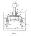
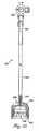
- FIG. 1presents a cross-sectional side view of one embodiment of the present invention.
- FIG. 2presents a perspective view of the embodiment of the invention depicted in FIG. 1, being used to manipulate the heart.
- FIG. 3 apresents a cross-sectional side view of another embodiment of the present invention, being used to engage the apex of the heart.
- FIG. 3 bpresents a cross-sectional side view of another embodiment of the present invention, being used to engage the apex of the heart.
- FIG. 4presents a cross-sectional side view of another embodiment of the present invention, being used to administer medicinal agents to the lumen of the pericardial sac.
- FIG. 5presents a cross-sectional side view of another embodiment of the present invention.
- FIG. 6presents a cross-sectional side view of the embodiment of the invention depicted in FIG. 5, with shaft partially withdrawn.
- FIG. 7presents a cross-sectional side view of the embodiment of the invention depicted in FIG. 5, with shaft partially withdrawn and engaging the apex of the heart.
- FIG. 8presents a cross-sectional side view of another embodiment of the present invention.
- FIG. 9presents a top view of another embodiment of the present invention.
- FIG. 10presents a cross-sectional side view of the embodiment depicted in FIG. 9 .
- FIG. 11presents a close-up cross-sectional view of a portion of a skirt-like member as depicted in FIG. 10 .
- FIG. 12presents a top view of another embodiment of the present invention.
- FIG. 13presents a top view of another embodiment of the present invention.
- FIG. 14presents a perspective view of an embodiment of the invention as depicted in FIG. 13, applied to the heart.
- FIG. 15presents a perspective view of an embodiment of the invention as depicted in FIG. 9, applied to the heart.
- FIG. 16presents a top view of another embodiment of the present invention.
- FIG. 17presents a top view of another embodiment of the present invention.
- FIG. 18presents a perspective view of the embodiment of the invention depicted in FIG. 1 and the embodiment of the invention depicted in FIG. 17, applied to the heart.
- FIG. 19is a perspective view of a cup-like seal member according to another embodiment of the present invention.
- FIG. 20is a cross-sectional side view of the seal member of FIG. 19 .
- FIG. 21is a perspective view of a cup-like seal member according to another embodiment of the present invention.
- FIG. 22is a cross-sectional side view of the seal member of FIG. 21 .
- FIG. 23is a perspective view of a cup-like seal member according to another embodiment of the present invention.
- FIG. 24is a cross-sectional side view of the seal member of FIG. 23 .
- FIG. 25is a perspective view of a cup-like seal member according to another embodiment of the present invention.
- FIG. 26is a cross-sectional side view of the seal member of FIG. 25 .
- FIG. 27 ais an enlarged view of a skirt member associated with a seal member as shown in any of FIGS. 19-26.
- FIG. 27 bshows the skirt member of FIG. 27 a in use.
- FIG. 28is a side view of a seal member incorporating a reinforcing structure and a swivel connection in accordance with a further embodiment of the present invention.
- FIG. 29is bottom view of the seal member of FIG. 28 .
- FIG. 30is another side view of the seal member of FIG. 28 .
- FIG. 31is atop view of the seal member of FIG. 28 .
- FIG. 32is a bottom perspective view of the seal member of FIG. 28 .
- FIG. 33is a side view of a device incorporating a seal member as shown in FIG. 28 .
- FIG. 1is a cross-sectional view of a device 10 for organ manipulation, in accordance with an embodiment of the present invention.
- device 10may include a seal member 12 .
- Seal member 12may include cup-like member 14 .
- Cup-like member 14defines a general size and shape of the device 10 , and may include components to serve various purposes.
- cup-like member 14defines a generally circular structure suitable for forming a cup-like shape.
- Cup-like member 14may include a vacuum port 16 and a neck 18 suitable for receiving a vacuum tube 20 .
- Vacuum tube 20may be sealed in neck 18 with sealant 19 .
- Vacuum tube 20may include a valve such as stopcock 21 , to prevent air from moving through vacuum tube 20 , or to allow a quick release of vacuum pressure. Alternatively, a valve may be included in vacuum port 16 or neck 18 .
- the cup-like member 14may encompass a spacer 22 to prevent the tissue from being drawn too far into the chamber, and especially from being drawn into vacuum port 16 , when vacuum pressure is applied.
- spacer 22may be integrally formed with member 14 , spacer 22 is shown in FIG. 1 as a separate element. Spacer 22 may bear against an inner ring 25 . Spacer 22 may also be omitted from device 10 .
- Cup-like member 14may also include a flange 24 that aids the physical connection between cup-like member 14 and a skirt-like member 26 .
- the interior wall of cup-like member 14 and skirt-like member 26define a chamber 15 .
- cup-like member 14provides a firm structure by which device 10 may be securely gripped by a surgeon or by an instrument.
- Cup-like member 14may include a structure such as a handle, knob or other attachment (not shown) for this purpose.
- seal member 12can be made, in part, of a compliant material that will permit it to conform to the surface of the organ. In the case of engagement between seal member 12 and a heart, the compliant qualities of seal member 12 will permit seal member 12 to maintain contact while the heart is contracting and relaxing.
- adherence to the tissuemay be improved by application of the vacuum pressure by way of vacuum port 16 and vacuum tube 20 , where at least a portion of seal member 12 deforms and substantially forms a seal against the surface of the tissue.
- Vacuum pressuremay be supplied by a number of devices, such as by a syringe, and may be maintained by shutting stopcock 21 .
- a constant source of negative pressuremay be employed but is not necessary.
- Cup-like member 14may be formed from many materials, including thermoplastic such as polycarbonate, ABS, polysulfone, polyester and polyurethane, and including corrosion-resistant metals such as titanium, and including rigid and semi-rigid elastomers such as silicone rubber, natural rubber, synthetic rubber, and polyurethane. Cup-like member 14 may have a semi-rigid structure that may be somewhat compliant, but generally resistant to deformation. Skirt-like member 26 , in contrast, may be formed from a substantially compliant material, such as a silicone gel, hydrogel or closed cell foam. Skirt-like member 26 generally permits deformation upon contact with tissue. In this manner, cup-like member 14 imparts structural integrity to device 10 , while skirt-like member 26 provides a seal interface with the tissue. Also, the material forming skirt-like member 26 may be tacky, and thereby promote adhesion to the surface of the tissue.
- thermoplasticsuch as polycarbonate, ABS, polysulfone, polyester and polyurethane
- corrosion-resistant metals
- skirt-like member 26may be aided not only by the tackiness of the material, but the greater surface area provided at the seal interface upon deformation.
- Skirt-like member 26surrounds and may be coupled to flange 24 of cup-like member.
- the skirt-like memberincludes three components.
- One componentis main ring 28 , which is made of a compliant material that can deform, but will ordinarily not deform sufficiently as to rupture any seal.
- Main ring 28forms the general perimeter of the chamber 15 .
- a second componentis a reinforcing element 30 , partly embedded within the main ring 28 and anchored by a fixing mechanism 32 within flange 24 of cup-like member.
- reinforcing element 30is a spring or wire or shape-memory metal that generally resists deformation, and resultant collapse of main ring 28 under vacuum pressure. Reinforcing element 30 will allow main ring 28 to deform, but not to deform sufficiently as to rupture the seal during use. Employment of reinforcing element 30 may make it possible to make main ring 28 of skirt-like member 26 from less material.
- a third component of the skirt-like member 26is a layer of tacky material 34 on a region around main ring 28 where the seal will be formed. Tacky material 34 can adhere to organ tissue and can easily release in the absence of an applied vacuum. Tacky material 34 can also be compliant, permitting it to conform to the tissue in contact with it. Tacky material 34 can be coated or molded on main ring 28 , or bonded to main ring 28 as a discrete component. It is also possible that main ring 28 may be made entirely of tacky material 34 .
- a material suitable for the main ring 28 and the tacky material 34is a biocompatible silicone gel.
- suitable silicone gelsare MED-6340 and GEL-8150, both commercially available from NuSil Silicone Technologies of Carpinteria, Calif.
- Each gelis provided as a two-component liquid, the components designated Part A and Part B, which may be blended together.
- the properties of the siliconedepend generally upon the ratio of the mixture of Part A and Part B. In general, increasing the ratio of Part A to Part B produces a softer and tackier gel, while increasing the ratio of Part B to Part A produces a firmer and less tacky gel.
- silicone gelscan be manufactured with a range of crosslink densities.
- Silicone gelsgenerally do not contain reinforcing filler and therefore have a much higher degree of malleability and conformability to desired surfaces. As a result, the compliance and tackiness of silicone gel materials can be exploited in skirt-like member 26 to provide a more effective seal.
- the MED 6340 silicone gel materialfor example, exhibits a hardness characteristic such that a 19.5 gram shaft with a 6.35 mm diameter has been observed to penetrate the gel approximately 5 mm in approximately 5 seconds. This hardness characteristic is not a requirement, but merely representative of that exhibited by the commercially available MED 6340 material.
- the resulting silicone gelis suitable for use as main ring 28 .
- This mixing ratioproduces a material of little tackiness but of sufficient firmness that it will not disconnect from cup-like member. Even though the gel is firm, however, it is also soft and deformable, and in the shape of a cup may be pressed against organ tissue without causing serious trauma.
- a skirt-like member 26 made entirely from the firmer gelwould be expected to provide a good vacuum seal, but little tackiness and resultant adherence would be provided.
- a mixture blending MED-6340 in approximately a ratio of 4.5:5.5produces a comparable material suitable for use as main ring 28 .
- the resulting silicone gelis suitable for use as the tacky material 34 .
- the 1:1 mixing ratioproduces a material of considerable tackiness.
- the materialadheres well to slippery organs such as the heart, and is also easily moldable.
- the materialminimizes tissue abrasion.
- the materialis significantly softer than the silicone gel used to form the main ring 28 .
- the softer gelposes virtually no risk of trauma to the heart.
- a skirt-like member 26 made entirely from the softer gelwould be expected, however, to deform easily in the presence of a vacuum and quickly to rupture the vacuum seal.
- Skirt-like member 26can be formed, for example, by insert-molding of main ring 28 and tacky material 34 . Skirt-like member 26 then can be adhesively bonded orotherwise coupled to cup-like member 14 . Alternatively, cup-like member 14 also can be insert-molded with one or both of main ring 28 and tacky material 34 to produce the integrated seal member 12 .
- the combination of the softer gel forming tacky material 34 , the firmer gel forming the main ring 28 , and reinforcement from the reinforcing member 30produces a skirt-like member 26 that adheres to the surface of the heart, can conform to the surface of the heart when vacuum pressure is applied, yet will not deform to an extent to rupture the vacuum seal. This combination is able to absorb the shock of the beating heart without rupturing the seal and without damaging the cardiac tissue.
- the softness and greater surface area contact provided by the tacky material 34 upon deformationreduces the possibility of tissue trauma.
- FIG. 2shows device 10 of FIG. 1 in an exemplary application.
- a surgeon 40has obtained access to a heart 36 and has placed the device 10 over the apex 38 of the heart 36 .
- the heart 36has not been arrested.
- Device 10has adhered to apex 38 . If valve 21 on device 10 is left in the open position, the beating motion of the heart and the pressure of the surgeon's hand 40 will allow the heart tissue to move into the interior of chamber 15 , displacing air from the chamber. When the valve 21 is closed, atmospheric pressure will act to keep device 10 affixed to the heart tissue.
- the material employed to form skirt-like member 26is sufficiently flexible and compressible that skirt-like member 26 conforms tightly to the shape of heart 36 as shown in FIG.
- Removal of device 10can be accomplished by opening valve 21 , and allowing air to move through vacuum tube 20 to separate heart tissue from the inner surface of skirt-like member 26 .
- a syringe or other meanscan be used to force air through tube 20 to facilitate rapid detachment of device 10 from heart 36 .
- a source of vacuumcan be applied via vacuum tube 20 to remove air from inside device 10 and permit atmospheric pressure to hold the device to the tissue at apex 38 .
- Valve 21can be closed to prevent air from entering tube 20 . No additional source of external vacuum is then required.
- Tacky material 34 shown in FIG. 1helps promote adhesion.
- Compliant skirt-like member 26 of the devicehas conformed to the shape of apex 38 to create an airtight seal around the heart tissue.
- the compliance of skirt-like member 26allows the seal to be maintained even as the heart 36 contracts.
- Stopcock 21has been closed, so that a vacuum seal between device 10 and apex 38 may be maintained without constant application of vacuum pressure.
- surgeon 40may move the heart 36 by manipulating the device 10 or the vacuum tube 20 .
- FIG. 2shows the surgeon 40 beginning to lift the apex 38 by holding the vacuum tube 20 . By lifting the apex 38 , the surgeon 40 may move the heart 36 about and obtain access to other areas of the heart.
- the beating heart 36may be manipulated in this way so as not to compromise the heart's hemodynamic functions.
- the surgeon 40may lift the heart 36 with device 10 without causing a drop in aortic blood pressure.
- device 10provides a robust seal with the heart 36 , allowing manipulation of the heart 36 without the need for other supporting devices, and is also atraumatic to the apex 38 , avoiding ischemia, hematoma or other trauma.
- the overall size of the device 10 relative to the heartmay vary. In open-heart surgery, for example, a larger cup-like device may be most useful. In less invasive procedures, a smaller cup-like device, sized for insertion though an incision or through a cannula, may be more useful.
- FIG. 3 ashows a cutaway view of a device 42 for organ manipulation, in accordance with an embodiment of the present invention.
- Device 42is similar to device 10 of FIG. 1 in overall shape and construction, and device 42 is shown in an exemplary application similar to FIG. 2 .
- device 42has been placed over the apex 38 of the heart 36 .
- the heart 36has not been arrested.
- Device 42has adhered to apex 38 .
- Adherencemay be promoted by tacky material 34 and by the application of vacuum pressure.
- Device 42includes electrodes 46 , 48 , which may be used to pace the heart 36 by stimulation of the bundles of His 50 , 52 and Purkinje fibers 54 . Alternately, electrodes 47 and 49 can be positioned on spacer 22 , as shown in FIG. 3 b , or at other locations within the device.
- the normal pacemaker of the heartis the sinoatrial (SA) node (not shown in FIG. 3 a ).
- SA nodeis a small specialized region in the right atrial wall near the opening of the superior vena cava.
- An action potential initiated within the SA nodeordinarily spreads to both atria of the heart.
- An internodal pathwayextends from the SA node to the atrioventricular (AV) node (not shown in FIG.
- 3 awhich is a small bundle of specialized cardiac muscle cells near the junction of the atria and the ventricles 58 , 60 .
- Specialized cells known as the bundle of Hisextend from the AV node, through the ventricular septum 56 , where they divide into the left branch bundle of His 50 and the right branch bundle of His 52 .
- the branch bundles of His 50 , 52curve around the tip of the ventricular chambers 60 , 58 and travel back toward the atria along the outer walls of the heart 36 .
- the impulsetravels rapidly down the bundles of His 50 , 52 .
- Purkinje fibers 54extend from the bundles of His 50 , 52 and spread throughout the ventricular myocardium 62 .
- the impulse transmitted by the bundles of His 50 , 52is carried throughout the ventricular myocardium 62 by Purkinje fibers 54 .
- the bundles of His 50 , 52 and Purkinje fibers 54have a normal rate of action potential discharge of 20 to 40 action potentials per minute. Stimulation of the bundles of His 50 , 52 and Purkinje fibers 54 may cause the ventricular myocardium to beat at a faster rate and thus to help pace the heart 36 .
- Electrodes 46 , 48 , 47 and 49which may be coupled to a voltage or current source (not shown in FIGS.
- 3 a or 3 bvia conductors, may in this way be used to stimulate the bundles of His 50 , 52 and Purkinje fibers 54 and help pace the heart 36 .
- skirt-like member 28adheres atraumatically to the apex 38
- the device 42can remain on the apex 38 for long periods of time without causing hematoma or other trauma.
- the placement of device 42 on the apex 38allows for minimal interference with the surgical field. Consequently, device 42 can pace the heart 36 when needed, and can remain in place when pacing is not required.
- FIG. 4shows a cutaway view of device 64 for organ manipulation, in accordance with an embodiment of the present invention.
- Device 64is similar to device 10 of FIG. 1 .
- Device 64is shown in another exemplary application.
- the pericardial sac 66 surrounding the hearthas not been opened.
- the pericardial sac 66is a double-walled membranous sac that encloses the heart 36 .
- the sac 66is a tough, fibrous membrane known as the pericardium 68 .
- the surface of the heartis known as the epicardium 70 .
- Pericardial fluid in the sac 72lubricates the epicardial layer 70 and reduces friction between the pericardial and epicardial layers as the heart 36 beats.
- Device 64 shown in FIG. 4is like the device 10 shown in FIG. 1, except that device 64 includes a port 74 to allow for drug delivery.
- a needle 76has been introduced through the port 74 .
- Device 64had been placed upon the pericardial sac 66 and adheres due to the tackiness of the tacky material 78 lining the skirt-like member 80 .
- Vacuum pressurehas been applied to draw the outer layer of the pericardium 68 toward the needle 76 . This procedure will generally not draw the epicardium 70 as much.
- needle 76By drawing the pericardium 68 toward needle 76 , needle 76 may penetrate only the pericardium 68 and not the epicardium 70 , and medicinal agents may be effectively delivered to the pericardial fluid 72 of the pericardial sac 66 . Delivery of medicinal agents in this manner may be useful, for example, when injecting epinephrine, or when treating a viral or bacterial infection affecting the pericardial sac 66 known as pericarditis.
- FIG. 5is a cross-sectional view of another device 82 for organ manipulation, in accordance with an embodiment of the present invention.
- Device 82may include a seal member 84 .
- Seal member 84may include a cup-like member 86 .
- Cup-like member 86defines a general size and shape of the device 82 , and as shown in FIG. 5 defines a generally circular structure suitable for forming a cup-like shape.
- Cup-like member 86may also include a flange 88 that aids the physical connection between member 86 and a skirt-like member 90 .
- Skirt-like member 90is similar to skirt-like member 26 in FIG. 1 .
- Skirt-like member 90optionally can include a reinforcing element 91 .
- Seal member 84may engage the surface of organ tissue. Seal member 84 can be made, in part, of a compliant material that will permit it to conform to the surface of the organ. Skirt-like member 90 may include tacky material 98 that can conform to and easily adhere to organ tissue. In addition, device 82 may include a membrane 92 affixed at an interface between cup-like member 86 and skirt-like member 90 . Membrane 92 and skirt-like member 90 define a chamber 100 . Membrane 92 may be constructed of a flexible airtight and watertight material that may be stretched without rupturing. Materials that may be suitable for use as membrane 92 may include elastomers such as silicone rubber.
- Elasticity of membrane 92may vary, but membrane of approximately 30 durometer may be sufficiently elastic.
- a disk 94 made of substantially semi-rigid or hard elastomer materialmay be affixed to the center of membrane 92 .
- membrane 92is affixed to disk 94 at every point of contact between membrane 92 and disk 94 .
- a shaft 96 made of substantially rigid materialmay be affixed to the center of disk 94 .
- Disk 94would preferably be nonuniform in thickness, i.e., narrowed or thinned at the extremities.
- Cup-like member 86may include an aperture 102 through which shaft 96 may extend.
- FIG. 6is a cross-sectional view of device 82 .
- FIG. 6is like FIG. 5, except shaft 96 is shown partly extracted.
- a stopping mechanismsuch as a thumbscrew or a clamp may be employed to maintain the position of shaft 96 relative to member 86 .
- FIG. 7shows device 82 of FIG. 5 and FIG. 6 in engagement with the apex 38 of a heart 36 .
- Device 82adheres to the apex 38 in part due to the compliant tacky material 98 , upon the extraction of shaft 96 through aperture 102 , drawing the tissue into cavity 100 .
- the adherencemay be created without a vacuum source, such as a pump or a syringe.
- tissuemay be drawn into chamber 100 to an extent that the tissue contacts membrane 92 .
- FIG. 8is a cross-sectional view of another device 104 for organ manipulation, in accordance with an embodiment of the present invention.
- Device 104is similar to device 82 in FIG. 5 in that it includes a membrane 108 preferably manufactured of a flexible airtight and watertight material, affixed at an interface between cup-like member 112 and skirt-like member 106 .
- Cup-like member 112may include an aperture 118 and a neck 120 suitable for receiving a fluid tube 114 .
- Fluid tube 114may be sealed in neck 120 with sealant 116 .
- a first chamber 110is defined by membrane 108 and skirt-like member 106 .
- a second chamber 122is defined by membrane 108 , the interior surface of cup-like member 112 , and fluid tube 114 .
- Second chamber 122is preferably filled with a liquid 124 , such as water or saline solution.
- a liquid 124such as water or saline solution.
- device 104may adhere to the tissue in part due to compliant tacky material 126 , and in part due to the reduced pressure created within first chamber 110 upon the extraction of liquid 124 through fluid tube 114 . Extraction of liquid 124 through fluid tube 114 hydraulically draws the tissue into first cavity 110 .
- a stopping mechanismsuch as a valve or stopcock (not shown) may be employed to stop the flow of liquid 124 through fluid tube 114 , thus promoting adherence by preventing liquid
- FIG. 9is a top view of another device 160 for organ manipulation, in accordance with an embodiment of the present invention.
- the seal member 162is formed from a structural member 164 and two skirt-like members 166 , 168 .
- Structural member 164defines a size and generally annular shape suitable for forming a ring-like structure.
- the ringmay be of any shape, but the oval shape with a generally oval-shaped inner diameter and a generally oval-shaped outer diameter as shown in FIG. 9 is exemplary.
- the ringmay be generally planar or may be curved to conform to the surface of an organ such as the heart.
- Seal member 162may include a vacuum port 150 and a neck 152 suitable for receiving a vacuum tube 154 .
- Vacuum tube 154may include a valve such as stopcock (not shown) to prevent air from moving through vacuum tube 154 , or to allow a quick release of vacuum pressure. Alternatively, a valve may be included in vacuum port 150 or neck 152 .
- a skirt-like membermay be coupled to the inner diameter of the ring, or the outer diameter, or both.
- an inner skirt-like member 168is coupled to the inner diameter
- an outer skirt-like member 166is coupled to the outer diameter.
- structural member 164provides a firm structure by which the ring-like device 160 may be securely gripped by a surgeon or by an instrument.
- attachments 170have been affixed to the structural member 164 , to provide sites for secure gripping. Attachments 170 may be located elsewhere on the device.
- a structuresuch as a handle or a knob may also be suitable for providing a site for secure gripping.
- Structural member 164may be molded from many materials, including thermoplastic such as polycarbonate, ABS, polysulfone, polyester and polyurethane, and including corrosion-resistant metals such as titanium, and including rigid, semi-rigid and flexible elastomers such as silicone rubber and polyurethane.
- FIG. 10shows a side view of device 160 , which is the same ring-like device as depicted in FIG. 9 .
- Structural member 164 and skirt-like members 166 , 168define a chamber 167 substantially in the shape of a ring.
- Structural member 164may also include flanges 169 that aid the physical connection between structural member 164 and skirt-like members 166 , 168 .
- Skirt-like members 166 , 168may be reinforced by a reinforcing member (not shown in FIG. 10 ).
- FIG. 11presents a cross-sectional view of a typical skirt-like member 171 for device 160 of FIG. 9 .
- Skirt-like member 171may be an inner skirt-like member or an outer skirt-like member.
- Skirt-like member 171includes a main ring 172 , coupled to structural member 164 around flange 169 .
- skirt-like member 171may be reinforced with a reinforcing member 175 , similar to reinforcing member 30 shown in FIG. 1 .
- Reinforcing member 175may be partly embedded within the main ring 172 and anchored within flange 169 of structural member 164 .
- One embodiment of reinforcing member 175is a spring or wire or shape-memory metal that generally resists deformation, like reinforcing member 30 shown in FIG. 1 .
- Skirt-like member 171may include a tacky inner layer 174 bonded to the main ring member 172 .
- Main ring member 172may be formed from silicone gel in approximately the ratios described above for main ring 28 in FIG. 1 .
- Tacky inner layer 174may be formed from silicone gel in approximately the ratios described above for tacky material 34 in FIG. 1 .
- FIG. 12is a top view of another device 176 for organ manipulation, in accordance with an embodiment of the present invention.
- device 176 shown in FIG. 12has multiple chambers 178 , 180 , 182 , 184 , each in fluid contact with vacuum lines 190 , 192 , 194 , 196 via vacuum ports 191 , 193 , 195 , 197 .
- No chamberis in fluid contact with any other chamber.
- the vacuum pressure within each chambermay be created separately and independently from the other chambers, by means such as a syringe or vacuum pump (not shown).
- each chambermay be maintained separately and independently from the other chambers, by means such as a valve or stopcock (not shown).
- a valve or stopcocknot shown.
- the advantage of device 176is that each chamber is vacuum sealed independent of the others. A rupture a seal of one chamber will not necessarily cause a loss of vacuum pressure throughout the device 176 . In this way, device 176 may continue to adhere to the tissue even if the vacuum seal is ruptured at a site and vacuum pressure within one chamber is lost.
- FIG. 13is a top view of another device 200 for organ manipulation, in accordance with an embodiment of the present invention.
- device 200 shown in FIG. 13has a chamber 204 presented in a general C-shape instead of a ring.
- a gap 202separates the two tines or “feet” 206 , 208 of the device.
- the C-shapemay vary in shape and dimension, but the near-oval shape with a generally oval-shaped inner diameter and a generally oval-shaped outer diameter as shown in FIG. 13, is exemplary.
- Gap 202may also vary in size, such that the feet 206 , 208 need not touch each other, and device 200 could assume a general U-shape.
- FIG. 14shows the device 200 of FIG. 13 in an exemplary application.
- Device 200had been placed so that a vessel 210 on the surface of the heart 36 has been centered within the C-shape.
- the skirt-like members 212 , 214which are like skirt-like member 171 shown in FIG. 11, assist in providing adhesion to the desired site.
- Vacuum pressurehad been applied through the vacuum port 216 to provide additional adherence to the surface of the heart 36 .
- the inner diameter of the device 200forms a field 218 for the surgeon. Within field 218 , the contractions of the heart 36 may be reduced, although the heart 36 continues to beat, providing a tissue stabilizing effect. The surgeon may access the vessel 210 within the field 218 , without arresting the heart 36 .
- an itemmay be applied to vessel 210 within field 218 .
- vessel 210 or other tissue within field 218may be seized by a medical instrument such as a hemostat.
- a surgeonmay perform a vascular graft in which a vessel from another area of the body 219 is physically attached to vessel 210 , perhaps bypassing a blockage in vessel 210 and supplying blood to regions of the heart 36 normally supplied by vessel 210 .
- itmay be desirable to remove device 200 without disturbing other items within the field such as vessel 219 .
- the C-shape configuration of device 200may allow device 200 to be removed from the heart, by separating the gap 202 and maneuvering device 200 around the other items.
- FIG. 15shows an exemplary application of device 160 shown in FIG. 9 .
- Device 160 in FIG. 15is held by a securing device 220 at attachment points 170 .
- Securing device 220may in turn be affixed to a relatively immobile object, such as a rib spreader (not shown) or an operating table (not shown).
- a relatively immobile objectsuch as a rib spreader (not shown) or an operating table (not shown).
- FIG. 16is a top view of another device 224 for organ manipulation, in accordance with an embodiment of the present invention.
- Device 224is similar in overall shape and construction to the device 200 shown in FIG. 13, and further includes a first electrode 226 .
- First electrode 226is connected to a power supply (not shown) via wire 228 that may follow the same path as vacuum tube 230 .
- First electrode 226may be affixed to another element of device 224 at various locations.
- First electrode 226may be attached to or partly incorporated within chamber 232 , for example, or attached to or partly incorporated within a skirt-like member 234 .
- First electrode 226ordinarily would be located such that electrode 226 would come in contact with tissue when device 224 is engaged against the tissue.
- a second matching electrodeconnected to the same power supply, may be attached to a scalpel (not shown).
- a scalpel(not shown).
- Such an arrangement of electrodesmay be useful for bipolar surgery, in which electric current is a part of the procedure.
- current passing between the second scalpel electrode and the first electrode 226 on device 224may serve to provide immediate cauterization to an incision.
- FIG. 17is a top view of another device 236 for organ manipulation, in accordance with an embodiment of the present invention.
- Device 236is similar in overall shape and construction to the device 224 shown in FIG. 16 .
- device 236includes a first electrode 238 .
- second electrode 240is included within device 236 , rather than within another surgical instrument. Both electrodes 242 , 244 preferably come in contact with tissue when device 236 is engaged against the tissue. Electrodes 238 , 240 may be connected to associated circuitry by wires 242 , 244 .
- first electrode 238may be capable of sending electrical signals
- second electrode 240may be capable of substantially receiving the electrical signals sent by first electrode 238 .
- Such an arrangement of electrodesmay be useful in many kinds of surgical procedures, such as those in which electric current is a part of the procedure.
- a surgeonmay, for example, wish to measure the impedance or other characteristics of the tissue between the electrodes, or the time needed for an electrical signal to conduct along the tissue.
- the electrodesmay be connected to an external pulse generator and be useful in pacing the heart.
- FIG. 18provides a perspective view of two embodiments of the present invention, in two contemporaneous exemplary applications.
- One embodiment of the inventionis a cup-shaped device 10 , like the device shown in FIG. 1 or other embodiments such as 42 , 82 , 104 , 280 .
- Another embodimentis a C-shaped device 236 , as shown in FIG. 18 . Both devices 10 , 236 have been applied to the heart 36 at the same time.
- cup-shaped device 10has been adhered to the apex 38 of the heart 36 , in a manner like that depicted in FIG. 2 .
- a surgeoncan lift or turn the heart 36 to obtain access to areas of the organ not easily accessible.
- the surgeonmay then immobilize device 10 by securing it to a securing device 249 .
- device 10may be further immobilized by attaching the securing device 249 to either the rib expander or the operating table.
- the heart 36has been lifted and turned to allow access to a region of the right atrium 250 .
- C-shaped device 236has been applied to the atrium 250 in a manner similar to that shown in FIG. 14 . Engagement of C-shaped device 236 may stabilize the tissue within field 252 , relative to the rest of the heart.
- By further affixing device 236 to a securing device 220which is in turn attached to either a rib expander or the operating table.
- the surgeonmay perform an operation in the field 252 .
- the surgeonmay use an ablation probe to ablate tissue within the field 252 , and sever pathways of electrical conduction. Such a severing may be helpful, for example, as a treatment for a kind of arrhythmia.
- the surgeonmay measure a quantity such as conduction time or impedance using electrodes 238 , 240 .
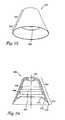
- FIG. 19is a perspective view of a cup-like seal member 260 according to another embodiment of the present invention.
- FIG. 20is a cross-sectional side view of the seal member of FIG. 19 .
- seal member 260may be somewhat similar to other seal members described above in that it defines an inner chamber 262 for application of vacuum pressure and affixation to the surface of the heart.
- Seal member 260may have an upper portion 264 formed form a semi-rigid material, e.g., a silicone elastomer of Shore A 30 to 70 durometer.
- a lower skirt-like member 266may be coupled to or molded with upper portion 264 , and may be formed from a substantially compliant material, such as a silicone elastomer of Shore A 5 to 10 elastomer. Alternatively, skirt-like member 266 may be formed from a silicone gel that is both compliant and tacky, enhancing sealing pressure. As mentioned above, the MED 6340 silicone gel material available from Nu-Sil may be acceptable for fabrication of skirt-like member 266 .
- Seal member 260may include a vacuum port 268 for communication with a vacuum tube and an external vacuum source. Also, seal member 260 may include two exterior circumferential ribs 270 , 272 that can be molded into upper portion 264 .
- Ribs 270 , 272provide seal member 260 with added strength to prevent collapse under vacuum pressure and consequent failure of the seal.
- skirt-like member 266provides a canted surface 274 that promotes sealing on both the inner and outer diameters 276 , 278 of the skirt-like member.
- FIG. 21is a perspective view of a cup-like seal member 280 according to another embodiment of the present invention.
- FIG. 22is a cross-sectional side view of the seal member 280 of FIG. 21 .
- Seal member 280corresponds to seal member 260 of FIG. 19 but omits circumferential ribs 270 , 272 .
- FIG. 23is a perspective view of a cup-like seal member 282 according to another embodiment of the present invention.
- FIG. 24is a cross-sectional side view of the seal member 282 of FIG. 23 .
- Seal member 282corresponds to seal member 280 of FIG. 21 but incorporates internal circumferential ribs 284 , 286 .
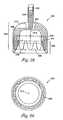
- FIG. 25is a perspective view of a cup-like seal member 288 according to another embodiment of the present invention.
- FIG. 26is a cross-sectional side view of the seal member 288 of FIG. 25 .
- Seal member 288corresponds to seal member 260 of FIG. 19 but instead of circumferential ribs 284 , 286 , incorporates external vertical ribs 290 .
- FIG. 27 ais an enlarged partial view of a skirt member associated with a seal member as shown in any of FIGS. 19-26.
- the conformable canted surface 274gives way and flexes inward and downward such that it contacts the tissue at both inner diameter 276 and outer diameter 278 , producing greater surface contact area, and promoting an effective seal.
- FIG. 27 billustrates canted surface 274 upon application to a tissue surface 275 .
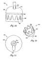
- FIG. 28is a side view of a seal member 292 incorporating a reinforcing structure and a swivel connection in accordance with a further embodiment of the present invention.
- FIG. 29is bottom view of the seal member 292 of FIG. 28 .
- FIG. 30is another side view of the seal member 292 of FIG. 28 .
- FIG. 31is a top view of the seal member 292 of FIG. 28 .
- FIG. 32is a bottom perspective view of the seal member 292 of FIG. 28 .
- seal member 292includes an upper portion 294 defining a semi-rigid cup-like member 296 with a set of finger-like extensions 298 . Molded around extensions 298 is a lower portion 299 having a compliant skirt-like member 300 .
- Cup-like member 296may be formed from a variety of materials such as silicone elastomers in the range of Shore A 30 to 70 durometer. Extensions 298 may be integrally formed with cup-like member 296 by molding. Skirt-like member 300 may extend below extensions 298 to a lip 302 and just above the extensions to a channel indicated by reference numeral 304 . Extensions 298 may thin in both thickness and width as they approach the lower extent of skirt-like member 300 . Extensions 298 provide added support to seal member 292 , helping to resist collapse under vacuum pressure. Skirt-like member 300 may be formed from a substantially compliant material, such as a silicone elastomer of Shore A 5 to 10 elastomer. Alternatively, skirt-like member 300 may be formed from a silicone gel such as Nu-Sil MED 6340 that is both compliant and tacky, enhancing sealing pressure.
- a substantially compliant materialsuch as a silicone elastomer of Shore A 5 to 10 elastomer.
- Seal member 292also may include a swivel-mount 306 designed to receive a vacuum tube 308 .
- Swivel 306may take the form of an extension or “stem” 309 that can be bonded inside a stainless steel tube 308 .
- Seal member 292defines a “notch-out” area 310 that accommodates the tube when the tube is bent relative to the seal member, e.g., at 90 degrees. In this manner, vacuum tube 308 can be bent relative to seal member 292 to permit positioning of the seal member over the apex of the heart while the vacuum tube is held by the surgeon at an angle to the apex.
- Stem 309is inserted into vacuum port 312 , which is positioned within a recess 314 .
- Cup recess area 314may have a width sufficient to permit swiveling of seal member 292 approximately 30 degrees relative to the longitudinal axis of stem 309 .
- seal member 292may be relatively simple to construct and reconstruct. The swivel capability permits the heart to twist and slightly bob with each beat while seal member 292 is affixed to the apex. Also, the seal member 292 is able to self-center on the apex by reducing side bending moments. Further, seal member 292 can be oriented at 90 degrees relative to the vacuum tube with the vacuum tube residing in notch-out area 310 to permit it to be mounted on the apex without heart manipulation. To lift the heart, the vacuum tube then gradually moves out of notch-out area 310 . As in other embodiments, seal member 292 and, in particular, skirt-like member 300 may incorporate electrodes and conductors for pacing or diagnosis.
- FIG. 33is side view of a device incorporating a seal member as shown in FIG. 28 .
- seal member 292may be coupled to a length of vacuum tubing 308 having a distal end 318 at seal member 292 and a proximal end 320 at a valve device 322 coupled to a vacuum source.
Landscapes
- Health & Medical Sciences (AREA)
- Life Sciences & Earth Sciences (AREA)
- Surgery (AREA)
- Heart & Thoracic Surgery (AREA)
- Engineering & Computer Science (AREA)
- Biomedical Technology (AREA)
- Nuclear Medicine, Radiotherapy & Molecular Imaging (AREA)
- Medical Informatics (AREA)
- Molecular Biology (AREA)
- Animal Behavior & Ethology (AREA)
- General Health & Medical Sciences (AREA)
- Public Health (AREA)
- Veterinary Medicine (AREA)
- Surgical Instruments (AREA)
Abstract
Description
Claims (98)
Priority Applications (8)
| Application Number | Priority Date | Filing Date | Title |
|---|---|---|---|
| US09/663,917US6641604B1 (en) | 2000-02-11 | 2000-09-18 | Devices and method for manipulation of organ tissue |
| US09/692,524US6558314B1 (en) | 2000-02-11 | 2000-10-19 | Devices and method for manipulation of organ tissue |
| CA002398220ACA2398220A1 (en) | 2000-02-11 | 2001-02-09 | Organ tissue manipulator |
| AU7205601AAU7205601A (en) | 2000-02-11 | 2001-02-09 | Organ tissue manipulator |
| EP01951119AEP1253858A1 (en) | 2000-02-11 | 2001-02-09 | Organ tissue manipulator |
| JP2001557475AJP2004502473A (en) | 2000-02-11 | 2001-02-09 | Treatment device for organ tissue |
| MXPA02007670AMXPA02007670A (en) | 2000-02-11 | 2001-02-09 | Organ tissue manipulator. |
| PCT/US2001/004236WO2001058361A1 (en) | 2000-02-11 | 2001-02-09 | Organ tissue manipulator |
Applications Claiming Priority (3)
| Application Number | Priority Date | Filing Date | Title |
|---|---|---|---|
| US18192500P | 2000-02-11 | 2000-02-11 | |
| US21029900P | 2000-06-08 | 2000-06-08 | |
| US09/663,917US6641604B1 (en) | 2000-02-11 | 2000-09-18 | Devices and method for manipulation of organ tissue |
Related Child Applications (1)
| Application Number | Title | Priority Date | Filing Date |
|---|---|---|---|
| US09/692,524Continuation-In-PartUS6558314B1 (en) | 2000-02-11 | 2000-10-19 | Devices and method for manipulation of organ tissue |
Publications (1)
| Publication Number | Publication Date |
|---|---|
| US6641604B1true US6641604B1 (en) | 2003-11-04 |
Family
ID=46149881
Family Applications (1)
| Application Number | Title | Priority Date | Filing Date |
|---|---|---|---|
| US09/663,917Expired - Fee RelatedUS6641604B1 (en) | 2000-02-11 | 2000-09-18 | Devices and method for manipulation of organ tissue |
Country Status (1)
| Country | Link |
|---|---|
| US (1) | US6641604B1 (en) |
Cited By (48)
| Publication number | Priority date | Publication date | Assignee | Title |
|---|---|---|---|---|
| US20020099389A1 (en)* | 1996-08-22 | 2002-07-25 | Michler Robert E. | Endovascular flexible stapling device |
| US6764444B2 (en) | 2002-06-28 | 2004-07-20 | Ethicon, Inc. | Mounting arrangement for suction device for surgical applications |
| US20040152997A1 (en)* | 2002-05-20 | 2004-08-05 | Davies Richard J. | Electrophysiological approaches to assess resection and tumor ablation margins and responses to drug therapy |
| US20040171917A1 (en)* | 2001-01-24 | 2004-09-02 | Paul David J. | Surgical instruments for stabilizing a localized portion of a beating heart |
| US20040253652A1 (en)* | 2002-05-20 | 2004-12-16 | Davies Richard J. | Method and system for detecting electrophysiological changes in pre-cancerous and cancerous breast tissue and epithelium |
| US6837852B2 (en) | 2002-06-28 | 2005-01-04 | Ethicon, Inc. | Control valve for suction device for surgical applications |
| US20050017021A1 (en)* | 2002-04-26 | 2005-01-27 | Jahns Scott E. | System, method and apparatus for regulating vacuum supplied to surgical tools |
| US20050203436A1 (en)* | 2002-05-20 | 2005-09-15 | Davies Richard J. | Method and system for detecting electrophysiological changes in pre-cancerous and cancerous tissue |
| US20050234289A1 (en)* | 2003-06-26 | 2005-10-20 | Anstadt Mark P | Therapeutic agent delivery apparatus with direct mechanical ventricular assistance capability |
| US20060100488A1 (en)* | 2002-05-20 | 2006-05-11 | Davies Richard J | Method and system for detecting electrophysiological changes in pre-cancerous and cancerous tissue |
| WO2006060431A1 (en)* | 2004-11-30 | 2006-06-08 | Medtronic, Inc. | Devices and methods for interstitial injection of biologic agents into tissue |
| US20060167334A1 (en)* | 2003-06-26 | 2006-07-27 | Anstadt Mark P | Method and apparatus for direct mechanical ventricular actuation with favorable conditioning and minimal heart stress |
| US20060241514A1 (en)* | 2005-04-21 | 2006-10-26 | Davies Richard J | Method and system for detecting electrophysiological changes in pre-cancerous and cancerous tissue and epithelium |
| US7165552B2 (en) | 2003-03-27 | 2007-01-23 | Cierra, Inc. | Methods and apparatus for treatment of patent foramen ovale |
| US7186251B2 (en) | 2003-03-27 | 2007-03-06 | Cierra, Inc. | Energy based devices and methods for treatment of patent foramen ovale |
| US20070102847A1 (en)* | 2005-06-20 | 2007-05-10 | Sony Corporation | Method of manufacturing suction cup, suction cup, and on-vehicle apparatus |
| US7293562B2 (en) | 2003-03-27 | 2007-11-13 | Cierra, Inc. | Energy based devices and methods for treatment of anatomic tissue defects |
| US7311701B2 (en) | 2003-06-10 | 2007-12-25 | Cierra, Inc. | Methods and apparatus for non-invasively treating atrial fibrillation using high intensity focused ultrasound |
| US20080009764A1 (en)* | 2005-04-21 | 2008-01-10 | Epi-Sci, Llc | Method and system for detecting electrophysiological changes in pre-cancerous and cancerous tissue and epithelium |
| US7367975B2 (en) | 2004-06-21 | 2008-05-06 | Cierra, Inc. | Energy based devices and methods for treatment of anatomic tissue defects |
| US20090171236A1 (en)* | 2007-12-11 | 2009-07-02 | Epi-Sci, Llc | Electrical bioimpedance analysis as a biomarker of breast density and/or breast cancer risk |
| US20090306535A1 (en)* | 2005-12-06 | 2009-12-10 | Epi-Sci, Llc | Method and System for Detecting Electrophysiological Changes in Pre-Cancerous and Cancerous Tissue and Epithelium |
| US7637924B2 (en) | 2003-03-27 | 2009-12-29 | Terumo Kabushiki Kaisha | Methods and apparatus for treatment of patent foramen ovale |
| WO2010009294A1 (en)* | 2008-07-18 | 2010-01-21 | Wake Forest University Heath Sciences | Apparatus and method for cardiac tissue modulation by topical application of vacuum to minimize cell death and damage |
| US7740623B2 (en)* | 2001-01-13 | 2010-06-22 | Medtronic, Inc. | Devices and methods for interstitial injection of biologic agents into tissue |
| US7744562B2 (en) | 2003-01-14 | 2010-06-29 | Medtronics, Inc. | Devices and methods for interstitial injection of biologic agents into tissue |
| US7914527B2 (en) | 2003-03-27 | 2011-03-29 | Terumo Kabushiki Kaisha | Energy based devices and methods for treatment of patent foramen ovale |
| US7972330B2 (en) | 2003-03-27 | 2011-07-05 | Terumo Kabushiki Kaisha | Methods and apparatus for closing a layered tissue defect |
| US8021362B2 (en) | 2003-03-27 | 2011-09-20 | Terumo Kabushiki Kaisha | Methods and apparatus for closing a layered tissue defect |
| US8109274B2 (en) | 2005-04-11 | 2012-02-07 | Terumo Kabushiki Kaisha | Methods and electrode apparatus to achieve a closure of a layered tissue defect |
| US8162817B2 (en) | 1997-09-17 | 2012-04-24 | Maquet Cardiovascular Llc | Device to permit offpump beating heart coronary bypass surgery |
| US8267960B2 (en) | 2008-01-09 | 2012-09-18 | Wake Forest University Health Sciences | Device and method for treating central nervous system pathology |
| US8377016B2 (en) | 2007-01-10 | 2013-02-19 | Wake Forest University Health Sciences | Apparatus and method for wound treatment employing periodic sub-atmospheric pressure |
| US8382654B2 (en) | 1996-02-20 | 2013-02-26 | Maquet Cardiovascular Llc | Surgical devices for imposing a negative pressure to stabilize the cardiac tissue during surgery |
| US20130165969A1 (en)* | 2010-07-13 | 2013-06-27 | Universite Joseph Fourier | Device for controlling a blood flow produced in a hemorrhagic area |
| US8641598B2 (en) | 2003-07-08 | 2014-02-04 | Maquet Cardiovascular Llc | Organ manipulator apparatus |
| US8753266B2 (en) | 1997-09-17 | 2014-06-17 | Maquet Cardiovascular Llc | Device to permit offpump beating heart coronary bypass surgery |
| US8834520B2 (en) | 2007-10-10 | 2014-09-16 | Wake Forest University | Devices and methods for treating spinal cord tissue |
| US20140303641A1 (en)* | 2013-03-25 | 2014-10-09 | Richard Wolf Gmbh | Colpotransilluminator for arrangement in a uterus manipulator |
| US9022998B2 (en) | 2010-02-26 | 2015-05-05 | Maquet Cardiovascular Llc | Blower instrument, apparatus and methods of using |
| US20160008081A1 (en)* | 2013-01-14 | 2016-01-14 | Kirk Promotion Ltd | Surgical assisting device |
| US20210153929A1 (en)* | 2018-08-03 | 2021-05-27 | Olympus Corporation | Treatment tool and treatment tool airtight member |
| US11383076B2 (en) | 2020-10-01 | 2022-07-12 | Lifebridge Technologies, Llc | Pump regulation based on heart size and function |
| US20220226011A1 (en)* | 2019-05-16 | 2022-07-21 | Kyoto University | Organ sucking and grasping tool |
| US11896812B1 (en) | 2023-01-27 | 2024-02-13 | Lifebridge Technologies Llc | Versatile modular heart pump for non-blood contacting ventricular function augmentation |
| US12115363B1 (en) | 2023-08-10 | 2024-10-15 | Lifebridge Technologies Llc | System and method for introducing a construct either on or around the surface of the heart |
| US12263332B2 (en) | 2022-09-13 | 2025-04-01 | Lifebridge Technologies Llc | Material characteristics ideal for providing either partial or total mechanical support to the failing or arrested heart and method for developing ideal characteristics for underlying cardiac disorders |
| US12440338B2 (en) | 2023-12-05 | 2025-10-14 | Lifebridge Technologies Llc | Minimally invasive heart pump with modular adjustable construct insertion |
Citations (89)
| Publication number | Priority date | Publication date | Assignee | Title |
|---|---|---|---|---|
| US3590815A (en) | 1969-01-07 | 1971-07-06 | Peter Shiff | Portable mechanical ventricular assistance device |
| US3608540A (en) | 1969-02-24 | 1971-09-28 | St Croix Research Co | Method and apparatus for aiding in the detection of breast cancer |
| US3613672A (en) | 1969-07-09 | 1971-10-19 | Peter Schiff | Mechanical ventricular assistance cup |
| US3786801A (en) | 1969-02-24 | 1974-01-22 | Diagnostic Inc | Method and apparatus for aiding in the detection of breast cancer |
| US3811443A (en) | 1971-01-22 | 1974-05-21 | Agrophysic Inc | Method and apparatus for artificial insemination |
| US3926192A (en) | 1974-08-12 | 1975-12-16 | Maren Harold B Van | Atraumatic uterine director |
| US3952737A (en) | 1974-08-28 | 1976-04-27 | The Medevice Company | Contraceptive |
| US4048990A (en) | 1976-09-17 | 1977-09-20 | Goetz Robert H | Heart massage apparatus |
| US4543949A (en) | 1979-12-31 | 1985-10-01 | University Patents, Inc. | Custom valved cervical cap |
| EP0157888A1 (en) | 1984-03-23 | 1985-10-16 | Storz, Karl, Dr.med. h.c. | Single hand operated hysteroscope |
| US4596566A (en) | 1984-10-26 | 1986-06-24 | Kay Dennis M | Ostomy appliance with suction securing chamber |
| US4635618A (en)* | 1978-01-19 | 1987-01-13 | Munz Otto J | Skin lifting device for body exercising purposes |
| US4732148A (en) | 1983-11-17 | 1988-03-22 | Lri L.P. | Method for performing ophthalmic laser surgery |
| EP0319394A1 (en) | 1987-11-30 | 1989-06-07 | Milos Sovak | Hysterography device |
| US4973300A (en) | 1989-09-22 | 1990-11-27 | Pioneering Technologies, Inc. | Cardiac sling for circumflex coronary artery surgery |
| US4991574A (en) | 1987-07-22 | 1991-02-12 | Dow Corning Corporation | Surgical dressing |
| US5119804A (en) | 1990-11-19 | 1992-06-09 | Anstadt George L | Heart massage apparatus |
| EP0502485A1 (en) | 1991-03-06 | 1992-09-09 | D.D. S.r.l. | Device for the lavage, for therapeutic or hygiene purposes, of human and animal internal ducts |
| US5248304A (en) | 1992-05-29 | 1993-09-28 | Michael Vigdorchik | Single use intrauterine injector |
| US5259836A (en) | 1987-11-30 | 1993-11-09 | Cook Group, Incorporated | Hysterography device and method |
| US5282785A (en) | 1990-06-15 | 1994-02-01 | Cortrak Medical, Inc. | Drug delivery apparatus and method |
| US5423878A (en) | 1984-03-06 | 1995-06-13 | Ep Technologies, Inc. | Catheter and associated system for pacing the heart |
| US5497771A (en) | 1993-04-02 | 1996-03-12 | Mipm Mammendorfer Institut Fuer Physik Und Medizin Gmbh | Apparatus for measuring the oxygen saturation of fetuses during childbirth |
| US5499971A (en) | 1990-06-15 | 1996-03-19 | Cortrak Medical, Inc. | Method for iontophoretically delivering drug adjacent to a heart |
| US5507741A (en) | 1983-11-17 | 1996-04-16 | L'esperance, Jr.; Francis A. | Ophthalmic method for laser surgery of the cornea |
| US5509890A (en) | 1993-12-16 | 1996-04-23 | Kazama; Shigeru | Heart retractor |
| US5536243A (en) | 1994-12-13 | 1996-07-16 | Jeyendran; Rajasingam S. | Time-release insemination device |
| US5562658A (en) | 1994-03-25 | 1996-10-08 | Snj Company, Inc. | Laser-powered surgical device for making incisions of selected depth |
| US5651378A (en) | 1996-02-20 | 1997-07-29 | Cardiothoracic Systems, Inc. | Method of using vagal nerve stimulation in surgery |
| WO1997026828A1 (en) | 1996-01-23 | 1997-07-31 | Sergio Gentilli | Laparoscopic instrument for handling parenchymatous and cavum organs |
| EP0791330A2 (en) | 1996-02-20 | 1997-08-27 | Cardiothoracic Systems, Inc. | Surgical instruments and procedures for stabilizing the beating heart during coronary artery bypass graft surgery |
| US5665105A (en) | 1996-03-20 | 1997-09-09 | Snowden Pencer/Genzyme Corporation | Radially adjustable surgical instrument for heart surgery |
| US5676634A (en)* | 1994-03-30 | 1997-10-14 | Khouri Biomedical Research, Inc. | Method and apparatus for soft tissue enlargement with balanced force appliance |
| US5727569A (en) | 1996-02-20 | 1998-03-17 | Cardiothoracic Systems, Inc. | Surgical devices for imposing a negative pressure to fix the position of cardiac tissue during surgery |
| US5730757A (en) | 1996-02-20 | 1998-03-24 | Cardiothoracic Systems, Inc. | Access platform for internal mammary dissection |
| US5749892A (en) | 1994-08-31 | 1998-05-12 | Heartport, Inc. | Device for isolating a surgical site |
| US5762458A (en) | 1996-02-20 | 1998-06-09 | Computer Motion, Inc. | Method and apparatus for performing minimally invasive cardiac procedures |
| US5776154A (en) | 1996-02-20 | 1998-07-07 | Cardiothoracic Systems, Inc. | Surgical instruments for making precise incisions in a cardiac vessel |
| US5779661A (en) | 1995-12-11 | 1998-07-14 | Physion, S.R.L. | Method of treating dysfunctional bladder syndromes by electromotive drug administration |
| US5782746A (en) | 1996-02-15 | 1998-07-21 | Wright; John T. M. | Local cardiac immobilization surgical device |
| US5799661A (en) | 1993-02-22 | 1998-09-01 | Heartport, Inc. | Devices and methods for port-access multivessel coronary artery bypass surgery |
| WO1998037814A1 (en) | 1997-02-27 | 1998-09-03 | Masao Takahashi | A device to hold an anastomotic site of coronary artery motionless and bloodless for the bypass operation |
| US5810721A (en) | 1996-03-04 | 1998-09-22 | Heartport, Inc. | Soft tissue retractor and method for providing surgical access |
| US5836311A (en) | 1995-09-20 | 1998-11-17 | Medtronic, Inc. | Method and apparatus for temporarily immobilizing a local area of tissue |
| US5843019A (en) | 1992-01-07 | 1998-12-01 | Arthrocare Corporation | Shaped electrodes and methods for electrosurgical cutting and ablation |
| US5855583A (en) | 1996-02-20 | 1999-01-05 | Computer Motion, Inc. | Method and apparatus for performing minimally invasive cardiac procedures |
| US5865730A (en) | 1997-10-07 | 1999-02-02 | Ethicon Endo-Surgery, Inc. | Tissue stabilization device for use during surgery having remotely actuated feet |
| US5868763A (en) | 1996-09-16 | 1999-02-09 | Guidant Corporation | Means and methods for performing an anastomosis |
| US5871017A (en) | 1996-10-15 | 1999-02-16 | Mayer; Paul W. | Relative motion cancelling platform for surgery |
| US5871495A (en) | 1996-09-13 | 1999-02-16 | Eclipse Surgical Technologies, Inc. | Method and apparatus for mechanical transmyocardial revascularization of the heart |
| US5871496A (en) | 1996-03-20 | 1999-02-16 | Cardiothoracic Systems, Inc. | Surgical instrument for facilitating the detachment of an artery and the like |
| US5875782A (en) | 1996-11-14 | 1999-03-02 | Cardiothoracic Systems, Inc. | Methods and devices for minimally invasive coronary artery revascularization on a beating heart without cardiopulmonary bypass |
| US5885271A (en) | 1997-03-14 | 1999-03-23 | Millennium Cardiac Strategies, Inc. | Device for regional immobilization of a compliant body |
| US5888247A (en) | 1995-04-10 | 1999-03-30 | Cardiothoracic Systems, Inc | Method for coronary artery bypass |
| US5891017A (en) | 1997-01-31 | 1999-04-06 | Baxter Research Medical, Inc. | Surgical stabilizer and method for isolating and immobilizing cardiac tissue |
| US5894843A (en) | 1996-02-20 | 1999-04-20 | Cardiothoracic Systems, Inc. | Surgical method for stabilizing the beating heart during coronary artery bypass graft surgery |
| US5899425A (en) | 1997-05-02 | 1999-05-04 | Medtronic, Inc. | Adjustable supporting bracket having plural ball and socket joints |
| US5910150A (en) | 1996-12-02 | 1999-06-08 | Angiotrax, Inc. | Apparatus for performing surgery |
| US5913876A (en) | 1996-02-20 | 1999-06-22 | Cardiothoracic Systems, Inc. | Method and apparatus for using vagus nerve stimulation in surgery |
| US5921979A (en) | 1996-12-18 | 1999-07-13 | Guidant Corporation | Apparatus and method for tissue and organ stabilization |
| US5944730A (en) | 1997-05-19 | 1999-08-31 | Cardio Medical Solutions, Inc. | Device and method for assisting end-to-side anastomosis |
| US5944736A (en) | 1996-02-20 | 1999-08-31 | Cardiothoracic Systems, Inc. | Access platform for internal mammary dissection |
| US5947896A (en) | 1996-04-26 | 1999-09-07 | United States Surgical Corporation | Heart stabilizer apparatus and method for use |
| US5957835A (en) | 1997-05-16 | 1999-09-28 | Guidant Corporation | Apparatus and method for cardiac stabilization and arterial occlusion |
| US5972020A (en) | 1997-02-14 | 1999-10-26 | Cardiothoracic Systems, Inc. | Surgical instrument for cardiac valve repair on the beating heart |
| US5971976A (en) | 1996-02-20 | 1999-10-26 | Computer Motion, Inc. | Motion minimization and compensation system for use in surgical procedures |
| US5976164A (en) | 1996-09-13 | 1999-11-02 | Eclipse Surgical Technologies, Inc. | Method and apparatus for myocardial revascularization and/or biopsy of the heart |
| US5976069A (en) | 1996-07-25 | 1999-11-02 | Guidant Corporation | Epicardial immobilization device |
| US5976123A (en) | 1996-07-30 | 1999-11-02 | Laser Aesthetics, Inc. | Heart stabilization |
| US5984864A (en) | 1997-10-07 | 1999-11-16 | Ethicon Endo-Surgery, Inc. | Tissue stabilization device for use during surgery |
| WO1999060930A2 (en) | 1998-05-29 | 1999-12-02 | Guidant Corporation | Beating heart coronary bypass surgical device |
| WO1999060929A2 (en) | 1998-05-29 | 1999-12-02 | Guidant Corporation | Beating heart coronary bypass surgical device |
| US6007523A (en) | 1998-09-28 | 1999-12-28 | Embol-X, Inc. | Suction support and method of use |
| US6007486A (en) | 1997-10-07 | 1999-12-28 | Ethicon Endo-Surgery, Inc. | Tissue stabilization device for use during surgery having a segmented shaft |
| US6013027A (en) | 1997-10-07 | 2000-01-11 | Ethicon Endo-Surgery, Inc. | Method for using a tissue stabilization device during surgery |
| US6015427A (en) | 1997-07-07 | 2000-01-18 | Eclipse Surgical Technologies, Inc. | Heart stabilizer with controllable stay suture and cutting element |
| US6019722A (en) | 1997-09-17 | 2000-02-01 | Guidant Corporation | Device to permit offpump beating heart coronary bypass surgery |
| WO2000010466A1 (en) | 1998-08-17 | 2000-03-02 | Coroneo Inc. | Pericardium retraction device for positioning a beating heart |
| EP0993806A2 (en) | 1998-09-15 | 2000-04-19 | Medtronic Inc. | Apparatus for temporarily immobilizing a local area of tissue |
| US6132363A (en)* | 1997-09-30 | 2000-10-17 | L.Vad Technology, Inc. | Cardiovascular support control system |
| WO2000062680A1 (en) | 1999-04-16 | 2000-10-26 | Medivas, Llc. | Device for stabilizing a treatment site and method of use |
| US6139538A (en) | 1997-10-06 | 2000-10-31 | Iotek, Inc. | Iontophoretic agent delivery to the female reproductive tract |
| WO2000074574A1 (en) | 1999-06-09 | 2000-12-14 | Medivas, Llc | Device for stabilizing a treatment site and method of use |
| WO2001012248A1 (en) | 1999-08-18 | 2001-02-22 | Iotek, Inc. | Device and method for delivery of agents to the female reproductive tract |
| WO2001017437A2 (en) | 1999-09-07 | 2001-03-15 | Cardiothoracic Systems, Inc. | Organ manipulator |
| US6238334B1 (en)* | 1997-11-03 | 2001-05-29 | Cardio Technologies, Inc. | Method and apparatus for assisting a heart to pump blood |
| US6290644B1 (en) | 1996-02-20 | 2001-09-18 | Cardiothoracic Systems, Inc. | Surgical instruments and procedures for stabilizing a localized portion of a beating heart |
| US6306085B1 (en) | 1996-09-20 | 2001-10-23 | United States Surgical Corporation | Surgical apparatus and method |
| US20020002372A1 (en) | 2000-04-27 | 2002-01-03 | Medtronic, Inc. | Suction stabilized epicardial ablation devices |
- 2000
- 2000-09-18USUS09/663,917patent/US6641604B1/ennot_activeExpired - Fee Related
Patent Citations (105)
| Publication number | Priority date | Publication date | Assignee | Title |
|---|---|---|---|---|
| US3590815A (en) | 1969-01-07 | 1971-07-06 | Peter Shiff | Portable mechanical ventricular assistance device |
| US3608540A (en) | 1969-02-24 | 1971-09-28 | St Croix Research Co | Method and apparatus for aiding in the detection of breast cancer |
| US3786801A (en) | 1969-02-24 | 1974-01-22 | Diagnostic Inc | Method and apparatus for aiding in the detection of breast cancer |
| US3613672A (en) | 1969-07-09 | 1971-10-19 | Peter Schiff | Mechanical ventricular assistance cup |
| US3811443A (en) | 1971-01-22 | 1974-05-21 | Agrophysic Inc | Method and apparatus for artificial insemination |
| US3926192A (en) | 1974-08-12 | 1975-12-16 | Maren Harold B Van | Atraumatic uterine director |
| US3952737A (en) | 1974-08-28 | 1976-04-27 | The Medevice Company | Contraceptive |
| US4048990A (en) | 1976-09-17 | 1977-09-20 | Goetz Robert H | Heart massage apparatus |
| US4635618A (en)* | 1978-01-19 | 1987-01-13 | Munz Otto J | Skin lifting device for body exercising purposes |
| US4543949A (en) | 1979-12-31 | 1985-10-01 | University Patents, Inc. | Custom valved cervical cap |
| US4732148A (en) | 1983-11-17 | 1988-03-22 | Lri L.P. | Method for performing ophthalmic laser surgery |
| US5507741A (en) | 1983-11-17 | 1996-04-16 | L'esperance, Jr.; Francis A. | Ophthalmic method for laser surgery of the cornea |
| US5423878A (en) | 1984-03-06 | 1995-06-13 | Ep Technologies, Inc. | Catheter and associated system for pacing the heart |
| EP0157888A1 (en) | 1984-03-23 | 1985-10-16 | Storz, Karl, Dr.med. h.c. | Single hand operated hysteroscope |
| US4596566A (en) | 1984-10-26 | 1986-06-24 | Kay Dennis M | Ostomy appliance with suction securing chamber |
| US4991574A (en) | 1987-07-22 | 1991-02-12 | Dow Corning Corporation | Surgical dressing |
| EP0319394A1 (en) | 1987-11-30 | 1989-06-07 | Milos Sovak | Hysterography device |
| US5259836A (en) | 1987-11-30 | 1993-11-09 | Cook Group, Incorporated | Hysterography device and method |
| US4973300A (en) | 1989-09-22 | 1990-11-27 | Pioneering Technologies, Inc. | Cardiac sling for circumflex coronary artery surgery |
| US5282785A (en) | 1990-06-15 | 1994-02-01 | Cortrak Medical, Inc. | Drug delivery apparatus and method |
| US5499971A (en) | 1990-06-15 | 1996-03-19 | Cortrak Medical, Inc. | Method for iontophoretically delivering drug adjacent to a heart |
| US5119804A (en) | 1990-11-19 | 1992-06-09 | Anstadt George L | Heart massage apparatus |
| EP0502485A1 (en) | 1991-03-06 | 1992-09-09 | D.D. S.r.l. | Device for the lavage, for therapeutic or hygiene purposes, of human and animal internal ducts |
| US5843019A (en) | 1992-01-07 | 1998-12-01 | Arthrocare Corporation | Shaped electrodes and methods for electrosurgical cutting and ablation |
| US5248304A (en) | 1992-05-29 | 1993-09-28 | Michael Vigdorchik | Single use intrauterine injector |
| US5799661A (en) | 1993-02-22 | 1998-09-01 | Heartport, Inc. | Devices and methods for port-access multivessel coronary artery bypass surgery |
| US5497771A (en) | 1993-04-02 | 1996-03-12 | Mipm Mammendorfer Institut Fuer Physik Und Medizin Gmbh | Apparatus for measuring the oxygen saturation of fetuses during childbirth |
| US5509890A (en) | 1993-12-16 | 1996-04-23 | Kazama; Shigeru | Heart retractor |
| US5562658A (en) | 1994-03-25 | 1996-10-08 | Snj Company, Inc. | Laser-powered surgical device for making incisions of selected depth |
| US5676634A (en)* | 1994-03-30 | 1997-10-14 | Khouri Biomedical Research, Inc. | Method and apparatus for soft tissue enlargement with balanced force appliance |
| US5749892A (en) | 1994-08-31 | 1998-05-12 | Heartport, Inc. | Device for isolating a surgical site |
| US6017304A (en) | 1994-08-31 | 2000-01-25 | Vierra; Mark A. | Device and method for isolating a surgical site |
| US5807243A (en) | 1994-08-31 | 1998-09-15 | Heartport, Inc. | Method for isolating a surgical site |
| US5536243A (en) | 1994-12-13 | 1996-07-16 | Jeyendran; Rajasingam S. | Time-release insemination device |
| US5888247A (en) | 1995-04-10 | 1999-03-30 | Cardiothoracic Systems, Inc | Method for coronary artery bypass |
| US5947125A (en) | 1995-04-10 | 1999-09-07 | Cardiothoracic Systems, Inc. | Method for coronary artery bypass |
| US5927284A (en) | 1995-09-20 | 1999-07-27 | Medtronic, Inc | Method and apparatus for temporarily immobilizing a local area of tissue |
| US6015378A (en) | 1995-09-20 | 2000-01-18 | Medtronic, Inc. | Method and apparatus for temporarily immobilizing a local area tissue |
| US5836311A (en) | 1995-09-20 | 1998-11-17 | Medtronic, Inc. | Method and apparatus for temporarily immobilizing a local area of tissue |
| US6371906B1 (en)* | 1995-09-20 | 2002-04-16 | Medtronic, Inc. | Method and apparatus for temporarily immobilizing a local area of tissue |
| US5779661A (en) | 1995-12-11 | 1998-07-14 | Physion, S.R.L. | Method of treating dysfunctional bladder syndromes by electromotive drug administration |
| WO1997026828A1 (en) | 1996-01-23 | 1997-07-31 | Sergio Gentilli | Laparoscopic instrument for handling parenchymatous and cavum organs |
| US5782746A (en) | 1996-02-15 | 1998-07-21 | Wright; John T. M. | Local cardiac immobilization surgical device |
| US5727569A (en) | 1996-02-20 | 1998-03-17 | Cardiothoracic Systems, Inc. | Surgical devices for imposing a negative pressure to fix the position of cardiac tissue during surgery |
| US5762458A (en) | 1996-02-20 | 1998-06-09 | Computer Motion, Inc. | Method and apparatus for performing minimally invasive cardiac procedures |
| US5776154A (en) | 1996-02-20 | 1998-07-07 | Cardiothoracic Systems, Inc. | Surgical instruments for making precise incisions in a cardiac vessel |
| US5855583A (en) | 1996-02-20 | 1999-01-05 | Computer Motion, Inc. | Method and apparatus for performing minimally invasive cardiac procedures |
| US6315717B1 (en) | 1996-02-20 | 2001-11-13 | Cardiothoracic Systems, Inc. | Surgical instruments for stabilizing the beating heart during coronary artery bypass graft surgery |
| US5651378A (en) | 1996-02-20 | 1997-07-29 | Cardiothoracic Systems, Inc. | Method of using vagal nerve stimulation in surgery |
| US5944736A (en) | 1996-02-20 | 1999-08-31 | Cardiothoracic Systems, Inc. | Access platform for internal mammary dissection |
| EP0791330A2 (en) | 1996-02-20 | 1997-08-27 | Cardiothoracic Systems, Inc. | Surgical instruments and procedures for stabilizing the beating heart during coronary artery bypass graft surgery |
| US6032672A (en) | 1996-02-20 | 2000-03-07 | Cardiothoracic Systems, Inc. | Surgical devices for imposing a negative pressure to stabilize cardiac tissue during surgery |
| US5913876A (en) | 1996-02-20 | 1999-06-22 | Cardiothoracic Systems, Inc. | Method and apparatus for using vagus nerve stimulation in surgery |
| US5971976A (en) | 1996-02-20 | 1999-10-26 | Computer Motion, Inc. | Motion minimization and compensation system for use in surgical procedures |
| US5730757A (en) | 1996-02-20 | 1998-03-24 | Cardiothoracic Systems, Inc. | Access platform for internal mammary dissection |
| US6290644B1 (en) | 1996-02-20 | 2001-09-18 | Cardiothoracic Systems, Inc. | Surgical instruments and procedures for stabilizing a localized portion of a beating heart |
| US5894843A (en) | 1996-02-20 | 1999-04-20 | Cardiothoracic Systems, Inc. | Surgical method for stabilizing the beating heart during coronary artery bypass graft surgery |
| US6036641A (en) | 1996-02-20 | 2000-03-14 | Cardiothoracic System, Inc. | Surgical instruments for stabilizing the beating heart during coronary artery bypass graft surgery |
| US5906607A (en) | 1996-02-20 | 1999-05-25 | Cardiothoracic Systems, Inc. | Surgical devices for imposing a negative pressure to stabilize cardiac tissue during surgery |
| US5810721A (en) | 1996-03-04 | 1998-09-22 | Heartport, Inc. | Soft tissue retractor and method for providing surgical access |
| US5665105A (en) | 1996-03-20 | 1997-09-09 | Snowden Pencer/Genzyme Corporation | Radially adjustable surgical instrument for heart surgery |
| US5871496A (en) | 1996-03-20 | 1999-02-16 | Cardiothoracic Systems, Inc. | Surgical instrument for facilitating the detachment of an artery and the like |
| US5947896A (en) | 1996-04-26 | 1999-09-07 | United States Surgical Corporation | Heart stabilizer apparatus and method for use |
| US5976069A (en) | 1996-07-25 | 1999-11-02 | Guidant Corporation | Epicardial immobilization device |
| US5976123A (en) | 1996-07-30 | 1999-11-02 | Laser Aesthetics, Inc. | Heart stabilization |
| US5871495A (en) | 1996-09-13 | 1999-02-16 | Eclipse Surgical Technologies, Inc. | Method and apparatus for mechanical transmyocardial revascularization of the heart |
| US5976164A (en) | 1996-09-13 | 1999-11-02 | Eclipse Surgical Technologies, Inc. | Method and apparatus for myocardial revascularization and/or biopsy of the heart |
| US5868763A (en) | 1996-09-16 | 1999-02-09 | Guidant Corporation | Means and methods for performing an anastomosis |
| US6306085B1 (en) | 1996-09-20 | 2001-10-23 | United States Surgical Corporation | Surgical apparatus and method |
| US5871017A (en) | 1996-10-15 | 1999-02-16 | Mayer; Paul W. | Relative motion cancelling platform for surgery |
| US5875782A (en) | 1996-11-14 | 1999-03-02 | Cardiothoracic Systems, Inc. | Methods and devices for minimally invasive coronary artery revascularization on a beating heart without cardiopulmonary bypass |
| US5931848A (en) | 1996-12-02 | 1999-08-03 | Angiotrax, Inc. | Methods for transluminally performing surgery |
| US5941893A (en) | 1996-12-02 | 1999-08-24 | Angiotrax, Inc. | Apparatus for transluminally performing surgery |
| US5910150A (en) | 1996-12-02 | 1999-06-08 | Angiotrax, Inc. | Apparatus for performing surgery |
| US6206827B1 (en) | 1996-12-18 | 2001-03-27 | Guidant Corporation | Apparatus and method for tissue and organ stabilization |
| US5921979A (en) | 1996-12-18 | 1999-07-13 | Guidant Corporation | Apparatus and method for tissue and organ stabilization |
| US5891017A (en) | 1997-01-31 | 1999-04-06 | Baxter Research Medical, Inc. | Surgical stabilizer and method for isolating and immobilizing cardiac tissue |
| US5972020A (en) | 1997-02-14 | 1999-10-26 | Cardiothoracic Systems, Inc. | Surgical instrument for cardiac valve repair on the beating heart |
| WO1998037814A1 (en) | 1997-02-27 | 1998-09-03 | Masao Takahashi | A device to hold an anastomotic site of coronary artery motionless and bloodless for the bypass operation |
| US5885271A (en) | 1997-03-14 | 1999-03-23 | Millennium Cardiac Strategies, Inc. | Device for regional immobilization of a compliant body |
| US5899425A (en) | 1997-05-02 | 1999-05-04 | Medtronic, Inc. | Adjustable supporting bracket having plural ball and socket joints |
| US5957835A (en) | 1997-05-16 | 1999-09-28 | Guidant Corporation | Apparatus and method for cardiac stabilization and arterial occlusion |
| US5944730A (en) | 1997-05-19 | 1999-08-31 | Cardio Medical Solutions, Inc. | Device and method for assisting end-to-side anastomosis |
| US6015427A (en) | 1997-07-07 | 2000-01-18 | Eclipse Surgical Technologies, Inc. | Heart stabilizer with controllable stay suture and cutting element |
| US6019722A (en) | 1997-09-17 | 2000-02-01 | Guidant Corporation | Device to permit offpump beating heart coronary bypass surgery |
| US6390976B1 (en)* | 1997-09-17 | 2002-05-21 | Origin Medsystems, Inc. | System to permit offpump beating heart coronary bypass surgery |
| US20010041827A1 (en) | 1997-09-17 | 2001-11-15 | Alan W. Cannon | Device to permit offpump beating heart coronary bypass surgery |
| US6132363A (en)* | 1997-09-30 | 2000-10-17 | L.Vad Technology, Inc. | Cardiovascular support control system |
| US6139538A (en) | 1997-10-06 | 2000-10-31 | Iotek, Inc. | Iontophoretic agent delivery to the female reproductive tract |
| US6013027A (en) | 1997-10-07 | 2000-01-11 | Ethicon Endo-Surgery, Inc. | Method for using a tissue stabilization device during surgery |
| US5865730A (en) | 1997-10-07 | 1999-02-02 | Ethicon Endo-Surgery, Inc. | Tissue stabilization device for use during surgery having remotely actuated feet |
| US6007486A (en) | 1997-10-07 | 1999-12-28 | Ethicon Endo-Surgery, Inc. | Tissue stabilization device for use during surgery having a segmented shaft |
| US5984864A (en) | 1997-10-07 | 1999-11-16 | Ethicon Endo-Surgery, Inc. | Tissue stabilization device for use during surgery |
| US6238334B1 (en)* | 1997-11-03 | 2001-05-29 | Cardio Technologies, Inc. | Method and apparatus for assisting a heart to pump blood |
| US6231585B1 (en) | 1997-11-20 | 2001-05-15 | Medivas, Llc | Device for stabilizing a treatment site and method of use |
| WO1999060929A2 (en) | 1998-05-29 | 1999-12-02 | Guidant Corporation | Beating heart coronary bypass surgical device |
| WO1999060930A2 (en) | 1998-05-29 | 1999-12-02 | Guidant Corporation | Beating heart coronary bypass surgical device |
| WO2000010466A1 (en) | 1998-08-17 | 2000-03-02 | Coroneo Inc. | Pericardium retraction device for positioning a beating heart |
| EP0993806A2 (en) | 1998-09-15 | 2000-04-19 | Medtronic Inc. | Apparatus for temporarily immobilizing a local area of tissue |
| US6007523A (en) | 1998-09-28 | 1999-12-28 | Embol-X, Inc. | Suction support and method of use |
| WO2000062680A1 (en) | 1999-04-16 | 2000-10-26 | Medivas, Llc. | Device for stabilizing a treatment site and method of use |
| WO2000074574A1 (en) | 1999-06-09 | 2000-12-14 | Medivas, Llc | Device for stabilizing a treatment site and method of use |
| WO2001012248A1 (en) | 1999-08-18 | 2001-02-22 | Iotek, Inc. | Device and method for delivery of agents to the female reproductive tract |
| WO2001017437A2 (en) | 1999-09-07 | 2001-03-15 | Cardiothoracic Systems, Inc. | Organ manipulator |
| US20020002372A1 (en) | 2000-04-27 | 2002-01-03 | Medtronic, Inc. | Suction stabilized epicardial ablation devices |
Non-Patent Citations (13)
| Title |
|---|
| "BST Series ‘Soft Touch’ Bellows Vacuum Cups," 2 pages, http://www.anver.com/document/vacuum%20components/vacuum%20cups/cups-soft-touch.htm. |
| "BST Series 'Soft Touch' Bellows Vacuum Cups," 2 pages, http://www.anver.com/document/vacuum%20components/vacuum%20cups/cups-soft-touch.htm. |
| "Cardiology Device Update," Nov. 15, 1999, Merrill Lynch. |
| "Pisco Pneumatic Equipment-Special Fittings," 8 pages, http://www.pisco.com/vacuum.htm. |
| "Vacuum Cup Ball Swivel Spring Suspension Assemblies," 2 pages, http://www.anver.com/document/vacuum20%components/vacuum%20cups/ball_swivel.htm. |
| "Vacuum Cup Mounting Crossarms, Slides and Suspension Assembly Components," 3 pages, http://www.anver.com/document/vacuum%20components/vacuum%20cups/cups-susp-parts.htm. |
| "Vacuum Cups and Suction Cups Ball Swivel Connectors," 2 pages, http://www.anver.com/document/vacuum%20components/vacuum%20cups/ball_swivel_connectors.htm. |
| "Vacuum Cups and Suction Cups for Eggs and Other Round Objects," 1 page, http://www.anver.com/document/vacuum%20components/vacuum%20cups/cups-egg.htm. |
| "Vacuum Cups with Bonded Metal Inserts," 2 pages, http://www.anver.com/document/vacuum%20components/vacuum%20cups/bonded_inserts.htm. |
| Baue et al., "Mechanical Ventricular Assistantance in Man," Supplement II to Circulation, vols. XXXVII and XXXVIII, pp. II-33-II36, Apr., 1968. |
| Borst et al., Circulation, 1999, 99:1400-1403. |
| Lowe et al., "Non-Blood-Contacting Riventricular Support: Direct Mechanical Ventricular Actuation," Operative Techniques in Thoracle and Cardiovascular Surgery, vol. 1, No. 1, pp. 345-351, Nov., 1999. |
| Nierich et al., "Heart Displacement During Off-Pump CABG: How Well Is It Tolerated?" The Society of Thoracic Surgeons, (Ann Thorac Surg 2000;70:466-72). |
Cited By (95)
| Publication number | Priority date | Publication date | Assignee | Title |
|---|---|---|---|---|
| US8382654B2 (en) | 1996-02-20 | 2013-02-26 | Maquet Cardiovascular Llc | Surgical devices for imposing a negative pressure to stabilize the cardiac tissue during surgery |
| US8167905B2 (en) | 1996-08-22 | 2012-05-01 | The Trustees Of Columbia University In The City Of New York | Endovascular flexible stapling device |
| US7794474B2 (en) | 1996-08-22 | 2010-09-14 | The Trustees Of Columbia University In The City Of New York | Endovascular flexible stapling device |
| US20020099389A1 (en)* | 1996-08-22 | 2002-07-25 | Michler Robert E. | Endovascular flexible stapling device |
| US8048110B2 (en) | 1996-08-22 | 2011-11-01 | The Trustees Of Columbia University In The City Of New York | Endovascular flexible stapling device |
| US9468437B2 (en) | 1996-08-22 | 2016-10-18 | The Trustees Of Columbia University In The City Of New York | Endovascular flexible stapling device |
| US8753266B2 (en) | 1997-09-17 | 2014-06-17 | Maquet Cardiovascular Llc | Device to permit offpump beating heart coronary bypass surgery |
| US8162817B2 (en) | 1997-09-17 | 2012-04-24 | Maquet Cardiovascular Llc | Device to permit offpump beating heart coronary bypass surgery |
| US7628780B2 (en)* | 2001-01-13 | 2009-12-08 | Medtronic, Inc. | Devices and methods for interstitial injection of biologic agents into tissue |
| US7740623B2 (en)* | 2001-01-13 | 2010-06-22 | Medtronic, Inc. | Devices and methods for interstitial injection of biologic agents into tissue |
| US20040171917A1 (en)* | 2001-01-24 | 2004-09-02 | Paul David J. | Surgical instruments for stabilizing a localized portion of a beating heart |
| US20080009679A1 (en)* | 2002-04-26 | 2008-01-10 | Jahns Scott K | System, method and apparatus for regulating vacuum supplied to surgical tools |
| US8057387B2 (en) | 2002-04-26 | 2011-11-15 | Medtronic, Inc. | System, method and apparatus for regulating vacuum supplied to surgical tools |
| US7066882B2 (en)* | 2002-04-26 | 2006-06-27 | Medtronic, Inc. | System, method and apparatus for regulating vacuum supplied to surgical tools |
| US20050017021A1 (en)* | 2002-04-26 | 2005-01-27 | Jahns Scott E. | System, method and apparatus for regulating vacuum supplied to surgical tools |
| US9037228B2 (en) | 2002-05-20 | 2015-05-19 | Epi-Sci, Llc | Method and system for detecting electrophysiological changes in pre-cancerous and cancerous tissue |
| US7630759B2 (en)* | 2002-05-20 | 2009-12-08 | Epi-Sci, Llc | Method and system for detecting electrophysiological changes in pre-cancerous and cancerous breast tissue and epithelium |
| US8280504B2 (en)* | 2002-05-20 | 2012-10-02 | Epi-Sci, Llc | Method and system for detecting electrophysiological changes in pre-cancerous and cancerous tissue |
| US20050203436A1 (en)* | 2002-05-20 | 2005-09-15 | Davies Richard J. | Method and system for detecting electrophysiological changes in pre-cancerous and cancerous tissue |
| US20080004543A1 (en)* | 2002-05-20 | 2008-01-03 | Epi-Sci, Llc | Electrophysiological approaches to assess resection and tumor ablation margins and responses to drug therapy |
| US9042977B2 (en) | 2002-05-20 | 2015-05-26 | Epi-Sci, Llc | Method and system for detecting electrophysiological changes in pre-cancerous and cancerous breast tissue and epithelium |
| US20060100488A1 (en)* | 2002-05-20 | 2006-05-11 | Davies Richard J | Method and system for detecting electrophysiological changes in pre-cancerous and cancerous tissue |
| US20100049079A1 (en)* | 2002-05-20 | 2010-02-25 | Epi-Sci, Llc | Method and system for detecting electrophysiological changes in pre-cancerous and cancerous breast tissue and epithelium |
| US20040253652A1 (en)* | 2002-05-20 | 2004-12-16 | Davies Richard J. | Method and system for detecting electrophysiological changes in pre-cancerous and cancerous breast tissue and epithelium |
| US8262575B2 (en) | 2002-05-20 | 2012-09-11 | Epi-Sci, Llc | Method and system for detecting electrophysiological changes in pre-cancerous and cancerous tissue |
| US8275453B2 (en) | 2002-05-20 | 2012-09-25 | Epi-Sci, Llc | Method and system for detecting electrophysiological changes in pre-cancerous and cancerous breast tissue and epithelium |
| US20040152997A1 (en)* | 2002-05-20 | 2004-08-05 | Davies Richard J. | Electrophysiological approaches to assess resection and tumor ablation margins and responses to drug therapy |
| US6764444B2 (en) | 2002-06-28 | 2004-07-20 | Ethicon, Inc. | Mounting arrangement for suction device for surgical applications |
| US6837852B2 (en) | 2002-06-28 | 2005-01-04 | Ethicon, Inc. | Control valve for suction device for surgical applications |
| US8273072B2 (en) | 2003-01-14 | 2012-09-25 | Medtronic, Inc. | Devices and methods for interstitial injection of biologic agents into tissue |
| US7744562B2 (en) | 2003-01-14 | 2010-06-29 | Medtronics, Inc. | Devices and methods for interstitial injection of biologic agents into tissue |
| US8852181B2 (en) | 2003-03-27 | 2014-10-07 | Terumo Kabushiki Kaisha | Energy based devices and methods for treatment of anatomic tissue defects |
| US8075554B2 (en) | 2003-03-27 | 2011-12-13 | Terumo Kabushiki Kaisha | Energy based devices and methods for treatment of patent foramen ovale |
| US7165552B2 (en) | 2003-03-27 | 2007-01-23 | Cierra, Inc. | Methods and apparatus for treatment of patent foramen ovale |
| US7186251B2 (en) | 2003-03-27 | 2007-03-06 | Cierra, Inc. | Energy based devices and methods for treatment of patent foramen ovale |
| US8465485B2 (en) | 2003-03-27 | 2013-06-18 | Terumo Kabushiki Kaisha | Energy based devices and methods for treatment of patent foramen ovale |
| US7914527B2 (en) | 2003-03-27 | 2011-03-29 | Terumo Kabushiki Kaisha | Energy based devices and methods for treatment of patent foramen ovale |
| US7922716B2 (en) | 2003-03-27 | 2011-04-12 | Terumo Kabushiki Kaisha | Energy based devices and methods for treatment of anatomic tissue defects |
| US7972330B2 (en) | 2003-03-27 | 2011-07-05 | Terumo Kabushiki Kaisha | Methods and apparatus for closing a layered tissue defect |
| US8021362B2 (en) | 2003-03-27 | 2011-09-20 | Terumo Kabushiki Kaisha | Methods and apparatus for closing a layered tissue defect |
| US8038669B2 (en) | 2003-03-27 | 2011-10-18 | Terumo Kabushiki Kaisha | Energy based devices and methods for treatment of patent foramen ovale |
| US8038671B2 (en) | 2003-03-27 | 2011-10-18 | Terumo Kabushiki Kaisha | Energy based devices and methods for treatment of patent foramen ovale |
| US8038673B2 (en) | 2003-03-27 | 2011-10-18 | Terumo Kabushiki Kaisha | Energy based devices and methods for treatment of patent foramen ovale |
| US8038672B2 (en) | 2003-03-27 | 2011-10-18 | Terumo Kabushiki Kaisha | Energy based devices and methods for treatment of patent foramen ovale |
| US7637924B2 (en) | 2003-03-27 | 2009-12-29 | Terumo Kabushiki Kaisha | Methods and apparatus for treatment of patent foramen ovale |
| US8052678B2 (en) | 2003-03-27 | 2011-11-08 | Terumo Kabushiki Kaisha | Energy based devices and methods for treatment of patent foramen ovale |
| US8057469B2 (en) | 2003-03-27 | 2011-11-15 | Terumo Kabushiki Kaisha | Methods and apparatus for treatment of patent foramen ovale |
| US7293562B2 (en) | 2003-03-27 | 2007-11-13 | Cierra, Inc. | Energy based devices and methods for treatment of anatomic tissue defects |
| US8066701B2 (en) | 2003-03-27 | 2011-11-29 | Terumo Kabushiki Kaisha | Energy based devices and methods for treatment of patent foramen ovale |
| US8070747B2 (en) | 2003-03-27 | 2011-12-06 | Terumo Kabushiki Kaisha | Energy based devices and methods for treatment of patent foramen ovale |
| US7311701B2 (en) | 2003-06-10 | 2007-12-25 | Cierra, Inc. | Methods and apparatus for non-invasively treating atrial fibrillation using high intensity focused ultrasound |
| US7494459B2 (en) | 2003-06-26 | 2009-02-24 | Biophan Technologies, Inc. | Sensor-equipped and algorithm-controlled direct mechanical ventricular assist device |
| US20060167334A1 (en)* | 2003-06-26 | 2006-07-27 | Anstadt Mark P | Method and apparatus for direct mechanical ventricular actuation with favorable conditioning and minimal heart stress |
| US20050234289A1 (en)* | 2003-06-26 | 2005-10-20 | Anstadt Mark P | Therapeutic agent delivery apparatus with direct mechanical ventricular assistance capability |
| US9402608B2 (en) | 2003-07-08 | 2016-08-02 | Maquet Cardiovascular Llc | Organ manipulator apparatus |
| US8641598B2 (en) | 2003-07-08 | 2014-02-04 | Maquet Cardiovascular Llc | Organ manipulator apparatus |
| US10383612B2 (en) | 2003-07-08 | 2019-08-20 | Maquet Cardiovascular Llc | Organ manipulator apparatus |
| US7367975B2 (en) | 2004-06-21 | 2008-05-06 | Cierra, Inc. | Energy based devices and methods for treatment of anatomic tissue defects |
| US8133221B2 (en) | 2004-06-21 | 2012-03-13 | Terumo Kabushiki Kaisha | Energy based devices and methods for treatment of anatomic tissue defects |
| WO2006060431A1 (en)* | 2004-11-30 | 2006-06-08 | Medtronic, Inc. | Devices and methods for interstitial injection of biologic agents into tissue |
| US8109274B2 (en) | 2005-04-11 | 2012-02-07 | Terumo Kabushiki Kaisha | Methods and electrode apparatus to achieve a closure of a layered tissue defect |
| US20060241514A1 (en)* | 2005-04-21 | 2006-10-26 | Davies Richard J | Method and system for detecting electrophysiological changes in pre-cancerous and cancerous tissue and epithelium |
| US20080009764A1 (en)* | 2005-04-21 | 2008-01-10 | Epi-Sci, Llc | Method and system for detecting electrophysiological changes in pre-cancerous and cancerous tissue and epithelium |
| US7853319B2 (en) | 2005-04-21 | 2010-12-14 | Epi-Sci, Llc | Method and system for detecting electrophysiological changes in pre-cancerous and cancerous tissue and epithelium |
| US20070102847A1 (en)* | 2005-06-20 | 2007-05-10 | Sony Corporation | Method of manufacturing suction cup, suction cup, and on-vehicle apparatus |
| US7850891B2 (en)* | 2005-06-20 | 2010-12-14 | Sony Corporation | Method of manufacturing suction cup |
| US20090306535A1 (en)* | 2005-12-06 | 2009-12-10 | Epi-Sci, Llc | Method and System for Detecting Electrophysiological Changes in Pre-Cancerous and Cancerous Tissue and Epithelium |
| US8332025B2 (en) | 2005-12-06 | 2012-12-11 | Epi-Sci, Llc | Method and system for detecting electrophysiological changes in pre-cancerous and cancerous tissue and epithelium |
| US9737455B2 (en) | 2007-01-10 | 2017-08-22 | Wake Forest Univeristy Health Sciences | Apparatus and method for wound treatment employing periodic sub-atmospheric pressure |
| US8377016B2 (en) | 2007-01-10 | 2013-02-19 | Wake Forest University Health Sciences | Apparatus and method for wound treatment employing periodic sub-atmospheric pressure |
| US8834520B2 (en) | 2007-10-10 | 2014-09-16 | Wake Forest University | Devices and methods for treating spinal cord tissue |
| US8738124B2 (en) | 2007-12-11 | 2014-05-27 | Epi-Sci, Llc | Electrical bioimpedance analysis as a biomarker of breast density and/or breast cancer risk |
| US20090171236A1 (en)* | 2007-12-11 | 2009-07-02 | Epi-Sci, Llc | Electrical bioimpedance analysis as a biomarker of breast density and/or breast cancer risk |
| US8764794B2 (en) | 2008-01-09 | 2014-07-01 | Wake Forest University Health Sciences | Device and method for treating central nervous system pathology |
| US8267960B2 (en) | 2008-01-09 | 2012-09-18 | Wake Forest University Health Sciences | Device and method for treating central nervous system pathology |
| US9289193B2 (en) | 2008-07-18 | 2016-03-22 | Wake Forest University Health Sciences | Apparatus and method for cardiac tissue modulation by topical application of vacuum to minimize cell death and damage |
| US10076318B2 (en) | 2008-07-18 | 2018-09-18 | Wake Forest University Health Sciences | Apparatus and method for cardiac tissue modulation by topical application of vacuum to minimize cell death and damage |
| WO2010009294A1 (en)* | 2008-07-18 | 2010-01-21 | Wake Forest University Heath Sciences | Apparatus and method for cardiac tissue modulation by topical application of vacuum to minimize cell death and damage |
| US9662434B2 (en) | 2010-02-26 | 2017-05-30 | Maquet Cardiovascular Llc | Blower instrument, apparatus and methods of using |
| US9022998B2 (en) | 2010-02-26 | 2015-05-05 | Maquet Cardiovascular Llc | Blower instrument, apparatus and methods of using |
| US20130165969A1 (en)* | 2010-07-13 | 2013-06-27 | Universite Joseph Fourier | Device for controlling a blood flow produced in a hemorrhagic area |
| US9919083B2 (en)* | 2010-07-13 | 2018-03-20 | Universite Joseph Fourier | Device for controlling a blood flow produced in a hemorrhagic area |
| US11083826B2 (en) | 2010-07-13 | 2021-08-10 | Hemosquid | Device for controlling a blood flow produced in a hemorrhagic area |
| US20160008081A1 (en)* | 2013-01-14 | 2016-01-14 | Kirk Promotion Ltd | Surgical assisting device |
| US20140303641A1 (en)* | 2013-03-25 | 2014-10-09 | Richard Wolf Gmbh | Colpotransilluminator for arrangement in a uterus manipulator |
| US9662141B2 (en)* | 2013-03-25 | 2017-05-30 | Richard Wolf Gmbh | Colpotransilluminator for arrangement in a uterus manipulator |
| US20210153929A1 (en)* | 2018-08-03 | 2021-05-27 | Olympus Corporation | Treatment tool and treatment tool airtight member |
| US12262907B2 (en)* | 2019-05-16 | 2025-04-01 | Kyoto University | Organ sucking and grasping tool |
| US20220226011A1 (en)* | 2019-05-16 | 2022-07-21 | Kyoto University | Organ sucking and grasping tool |
| US11383076B2 (en) | 2020-10-01 | 2022-07-12 | Lifebridge Technologies, Llc | Pump regulation based on heart size and function |
| US12263332B2 (en) | 2022-09-13 | 2025-04-01 | Lifebridge Technologies Llc | Material characteristics ideal for providing either partial or total mechanical support to the failing or arrested heart and method for developing ideal characteristics for underlying cardiac disorders |
| US11896812B1 (en) | 2023-01-27 | 2024-02-13 | Lifebridge Technologies Llc | Versatile modular heart pump for non-blood contacting ventricular function augmentation |
| US12115363B1 (en) | 2023-08-10 | 2024-10-15 | Lifebridge Technologies Llc | System and method for introducing a construct either on or around the surface of the heart |
| US12377259B2 (en) | 2023-08-10 | 2025-08-05 | Lifebridge Technologies Llc | System and method for introducing a construct either on or around the surface of the heart |
| US12440338B2 (en) | 2023-12-05 | 2025-10-14 | Lifebridge Technologies Llc | Minimally invasive heart pump with modular adjustable construct insertion |
Similar Documents
| Publication | Publication Date | Title |
|---|---|---|
| US6641604B1 (en) | Devices and method for manipulation of organ tissue | |
| US6558314B1 (en) | Devices and method for manipulation of organ tissue | |
| US20030078471A1 (en) | Manipulation of an organ | |
| US20190343503A1 (en) | Organ manipulator apparatus | |
| US7179224B2 (en) | Organ manipulator and positioner and methods of using the same | |
| JP3036686B2 (en) | Hemostatic holding device for vascular anastomosis used for coronary artery bypass surgery | |
| AU2005229011B2 (en) | Methods and apparatus providing suction-assisted tissue engagement | |
| US7097612B2 (en) | Tissue positioner | |
| US7186214B2 (en) | Instruments and methods for accessing an anatomic space | |
| US20030139646A1 (en) | Devices and methods for manipulation of organ tissue | |
| US20140142606A1 (en) | Hemostatic stabilization system | |
| US6988984B2 (en) | Device and method for the manipulation of organs | |
| US8114009B2 (en) | Coronary artery bypass grafting device | |
| JP2022055090A (en) | Medical device having curved shape for transferring implant piece | |
| CA2370095A1 (en) | Device for stabilizing a treatment site and method of use | |
| AU2001272056A2 (en) | Organ tissue manipulator | |
| US9603590B2 (en) | Single-arm stabilizer having suction capability | |
| WO2005102232A2 (en) | Suction cup epicardial stabilizer device for cardiac surgery | |
| AU2002347923A1 (en) | Manipulation of an organ | |
| AU2003219673A1 (en) | Devices and methods for manipulation of organ tissue |
Legal Events
| Date | Code | Title | Description |
|---|---|---|---|
| AS | Assignment | Owner name:IOTEK, INC., MINNESOTA Free format text:ASSIGNMENT OF ASSIGNORS INTEREST;ASSIGNORS:ADELMAN, THOMAS, G.;FOLEY, FREDERICK J.;SHARROW, JAMES S.;AND OTHERS;REEL/FRAME:011429/0056;SIGNING DATES FROM 20001214 TO 20001229 | |
| AS | Assignment | Owner name:TELEFLEX-CT DEVICES INCORPORATED, PENNSYLVANIA Free format text:ASSIGNMENT OF ASSIGNORS INTEREST;ASSIGNOR:GENZYME CORPORATION;REEL/FRAME:014363/0776 Effective date:20030630 Owner name:TELEFLEX-CT DEVICES INCORPORATED,PENNSYLVANIA Free format text:ASSIGNMENT OF ASSIGNORS INTEREST;ASSIGNOR:GENZYME CORPORATION;REEL/FRAME:014363/0776 Effective date:20030630 | |
| CC | Certificate of correction | ||
| AS | Assignment | Owner name:TELEFLEX-CT DEVICES INCORPORATED, MASSACHUSETTS Free format text:ASSIGNMENT OF ASSIGNORS INTEREST;ASSIGNOR:LOTEK INCORPORATED;REEL/FRAME:017626/0576 Effective date:20060117 Owner name:TELEFLEX-CT DEVICES INCORPORATED, MASSACHUSETTS Free format text:ASSIGNMENT OF ASSIGNORS INTEREST;ASSIGNOR:IOTEK INCORPORATED;REEL/FRAME:017626/0576 Effective date:20060117 | |
| REMI | Maintenance fee reminder mailed | ||
| LAPS | Lapse for failure to pay maintenance fees | ||
| STCH | Information on status: patent discontinuation | Free format text:PATENT EXPIRED DUE TO NONPAYMENT OF MAINTENANCE FEES UNDER 37 CFR 1.362 | |
| FP | Lapsed due to failure to pay maintenance fee | Effective date:20071104 |