US6641587B2 - Systems and methods for treating vertebral bodies - Google Patents
Systems and methods for treating vertebral bodiesDownload PDFInfo
- Publication number
- US6641587B2 US6641587B2US09/905,170US90517001AUS6641587B2US 6641587 B2US6641587 B2US 6641587B2US 90517001 AUS90517001 AUS 90517001AUS 6641587 B2US6641587 B2US 6641587B2
- Authority
- US
- United States
- Prior art keywords
- instrument
- sectional area
- cross sectional
- plunger
- interior
- Prior art date
- Legal status (The legal status is an assumption and is not a legal conclusion. Google has not performed a legal analysis and makes no representation as to the accuracy of the status listed.)
- Expired - Fee Related
Links
Images


Classifications
- A—HUMAN NECESSITIES
- A61—MEDICAL OR VETERINARY SCIENCE; HYGIENE
- A61B—DIAGNOSIS; SURGERY; IDENTIFICATION
- A61B17/00—Surgical instruments, devices or methods
- A61B17/56—Surgical instruments or methods for treatment of bones or joints; Devices specially adapted therefor
- A61B17/58—Surgical instruments or methods for treatment of bones or joints; Devices specially adapted therefor for osteosynthesis, e.g. bone plates, screws or setting implements
- A61B17/88—Osteosynthesis instruments; Methods or means for implanting or extracting internal or external fixation devices
- A61B17/885—Tools for expanding or compacting bones or discs or cavities therein
- A61B17/8852—Tools for expanding or compacting bones or discs or cavities therein capable of being assembled or enlarged, or changing shape, inside the bone or disc
- A61B17/8855—Tools for expanding or compacting bones or discs or cavities therein capable of being assembled or enlarged, or changing shape, inside the bone or disc inflatable, e.g. kyphoplasty balloons
- A—HUMAN NECESSITIES
- A61—MEDICAL OR VETERINARY SCIENCE; HYGIENE
- A61M—DEVICES FOR INTRODUCING MEDIA INTO, OR ONTO, THE BODY; DEVICES FOR TRANSDUCING BODY MEDIA OR FOR TAKING MEDIA FROM THE BODY; DEVICES FOR PRODUCING OR ENDING SLEEP OR STUPOR
- A61M31/00—Devices for introducing or retaining media, e.g. remedies, in cavities of the body
- A—HUMAN NECESSITIES
- A61—MEDICAL OR VETERINARY SCIENCE; HYGIENE
- A61B—DIAGNOSIS; SURGERY; IDENTIFICATION
- A61B17/00—Surgical instruments, devices or methods
- A61B17/16—Instruments for performing osteoclasis; Drills or chisels for bones; Trepans
- A61B17/1613—Component parts
- A61B17/1631—Special drive shafts, e.g. flexible shafts
- A—HUMAN NECESSITIES
- A61—MEDICAL OR VETERINARY SCIENCE; HYGIENE
- A61B—DIAGNOSIS; SURGERY; IDENTIFICATION
- A61B17/00—Surgical instruments, devices or methods
- A61B17/16—Instruments for performing osteoclasis; Drills or chisels for bones; Trepans
- A61B17/1662—Instruments for performing osteoclasis; Drills or chisels for bones; Trepans for particular parts of the body
- A61B17/1671—Instruments for performing osteoclasis; Drills or chisels for bones; Trepans for particular parts of the body for the spine
- A—HUMAN NECESSITIES
- A61—MEDICAL OR VETERINARY SCIENCE; HYGIENE
- A61B—DIAGNOSIS; SURGERY; IDENTIFICATION
- A61B17/00—Surgical instruments, devices or methods
- A61B17/16—Instruments for performing osteoclasis; Drills or chisels for bones; Trepans
- A61B17/17—Guides or aligning means for drills, mills, pins or wires
- A61B17/1739—Guides or aligning means for drills, mills, pins or wires specially adapted for particular parts of the body
- A61B17/1757—Guides or aligning means for drills, mills, pins or wires specially adapted for particular parts of the body for the spine
- A—HUMAN NECESSITIES
- A61—MEDICAL OR VETERINARY SCIENCE; HYGIENE
- A61B—DIAGNOSIS; SURGERY; IDENTIFICATION
- A61B17/00—Surgical instruments, devices or methods
- A61B17/56—Surgical instruments or methods for treatment of bones or joints; Devices specially adapted therefor
- A61B17/58—Surgical instruments or methods for treatment of bones or joints; Devices specially adapted therefor for osteosynthesis, e.g. bone plates, screws or setting implements
- A61B17/68—Internal fixation devices, including fasteners and spinal fixators, even if a part thereof projects from the skin
- A—HUMAN NECESSITIES
- A61—MEDICAL OR VETERINARY SCIENCE; HYGIENE
- A61B—DIAGNOSIS; SURGERY; IDENTIFICATION
- A61B17/00—Surgical instruments, devices or methods
- A61B17/56—Surgical instruments or methods for treatment of bones or joints; Devices specially adapted therefor
- A61B17/58—Surgical instruments or methods for treatment of bones or joints; Devices specially adapted therefor for osteosynthesis, e.g. bone plates, screws or setting implements
- A61B17/88—Osteosynthesis instruments; Methods or means for implanting or extracting internal or external fixation devices
- A61B17/8802—Equipment for handling bone cement or other fluid fillers
- A61B17/8805—Equipment for handling bone cement or other fluid fillers for introducing fluid filler into bone or extracting it
- A61B17/8816—Equipment for handling bone cement or other fluid fillers for introducing fluid filler into bone or extracting it characterised by the conduit, e.g. tube, along which fluid flows into the body or by conduit connections
- A—HUMAN NECESSITIES
- A61—MEDICAL OR VETERINARY SCIENCE; HYGIENE
- A61B—DIAGNOSIS; SURGERY; IDENTIFICATION
- A61B17/00—Surgical instruments, devices or methods
- A61B17/56—Surgical instruments or methods for treatment of bones or joints; Devices specially adapted therefor
- A61B17/58—Surgical instruments or methods for treatment of bones or joints; Devices specially adapted therefor for osteosynthesis, e.g. bone plates, screws or setting implements
- A61B17/88—Osteosynthesis instruments; Methods or means for implanting or extracting internal or external fixation devices
- A61B17/8802—Equipment for handling bone cement or other fluid fillers
- A61B17/8805—Equipment for handling bone cement or other fluid fillers for introducing fluid filler into bone or extracting it
- A61B17/8822—Equipment for handling bone cement or other fluid fillers for introducing fluid filler into bone or extracting it characterised by means facilitating expulsion of fluid from the introducer, e.g. a screw pump plunger, hydraulic force transmissions, application of vibrations or a vacuum
- A—HUMAN NECESSITIES
- A61—MEDICAL OR VETERINARY SCIENCE; HYGIENE
- A61F—FILTERS IMPLANTABLE INTO BLOOD VESSELS; PROSTHESES; DEVICES PROVIDING PATENCY TO, OR PREVENTING COLLAPSING OF, TUBULAR STRUCTURES OF THE BODY, e.g. STENTS; ORTHOPAEDIC, NURSING OR CONTRACEPTIVE DEVICES; FOMENTATION; TREATMENT OR PROTECTION OF EYES OR EARS; BANDAGES, DRESSINGS OR ABSORBENT PADS; FIRST-AID KITS
- A61F2/00—Filters implantable into blood vessels; Prostheses, i.e. artificial substitutes or replacements for parts of the body; Appliances for connecting them with the body; Devices providing patency to, or preventing collapsing of, tubular structures of the body, e.g. stents
- A61F2/02—Prostheses implantable into the body
- A61F2/30—Joints
- A61F2/46—Special tools for implanting artificial joints
- A61F2/4601—Special tools for implanting artificial joints for introducing bone substitute, for implanting bone graft implants or for compacting them in the bone cavity
- A—HUMAN NECESSITIES
- A61—MEDICAL OR VETERINARY SCIENCE; HYGIENE
- A61B—DIAGNOSIS; SURGERY; IDENTIFICATION
- A61B17/00—Surgical instruments, devices or methods
- A61B17/16—Instruments for performing osteoclasis; Drills or chisels for bones; Trepans
- A61B17/1662—Instruments for performing osteoclasis; Drills or chisels for bones; Trepans for particular parts of the body
- A—HUMAN NECESSITIES
- A61—MEDICAL OR VETERINARY SCIENCE; HYGIENE
- A61B—DIAGNOSIS; SURGERY; IDENTIFICATION
- A61B17/00—Surgical instruments, devices or methods
- A61B17/34—Trocars; Puncturing needles
- A61B17/3403—Needle locating or guiding means
- A—HUMAN NECESSITIES
- A61—MEDICAL OR VETERINARY SCIENCE; HYGIENE
- A61B—DIAGNOSIS; SURGERY; IDENTIFICATION
- A61B17/00—Surgical instruments, devices or methods
- A61B17/34—Trocars; Puncturing needles
- A61B17/3417—Details of tips or shafts, e.g. grooves, expandable, bendable; Multiple coaxial sliding cannulas, e.g. for dilating
- A—HUMAN NECESSITIES
- A61—MEDICAL OR VETERINARY SCIENCE; HYGIENE
- A61B—DIAGNOSIS; SURGERY; IDENTIFICATION
- A61B17/00—Surgical instruments, devices or methods
- A61B17/34—Trocars; Puncturing needles
- A61B17/3472—Trocars; Puncturing needles for bones, e.g. intraosseus injections
- A—HUMAN NECESSITIES
- A61—MEDICAL OR VETERINARY SCIENCE; HYGIENE
- A61B—DIAGNOSIS; SURGERY; IDENTIFICATION
- A61B17/00—Surgical instruments, devices or methods
- A61B17/56—Surgical instruments or methods for treatment of bones or joints; Devices specially adapted therefor
- A61B17/58—Surgical instruments or methods for treatment of bones or joints; Devices specially adapted therefor for osteosynthesis, e.g. bone plates, screws or setting implements
- A61B17/68—Internal fixation devices, including fasteners and spinal fixators, even if a part thereof projects from the skin
- A61B17/70—Spinal positioners or stabilisers, e.g. stabilisers comprising fluid filler in an implant
- A61B17/7094—Solid vertebral fillers; devices for inserting such fillers
- A61B17/7095—Solid vertebral fillers; devices for inserting such fillers the filler comprising unlinked macroscopic particles
- A—HUMAN NECESSITIES
- A61—MEDICAL OR VETERINARY SCIENCE; HYGIENE
- A61B—DIAGNOSIS; SURGERY; IDENTIFICATION
- A61B17/00—Surgical instruments, devices or methods
- A61B17/00234—Surgical instruments, devices or methods for minimally invasive surgery
- A61B2017/00238—Type of minimally invasive operation
- A61B2017/00261—Discectomy
- A—HUMAN NECESSITIES
- A61—MEDICAL OR VETERINARY SCIENCE; HYGIENE
- A61B—DIAGNOSIS; SURGERY; IDENTIFICATION
- A61B17/00—Surgical instruments, devices or methods
- A61B2017/0046—Surgical instruments, devices or methods with a releasable handle; with handle and operating part separable
- A61B2017/00464—Surgical instruments, devices or methods with a releasable handle; with handle and operating part separable for use with different instruments
- A—HUMAN NECESSITIES
- A61—MEDICAL OR VETERINARY SCIENCE; HYGIENE
- A61B—DIAGNOSIS; SURGERY; IDENTIFICATION
- A61B17/00—Surgical instruments, devices or methods
- A61B2017/00535—Surgical instruments, devices or methods pneumatically or hydraulically operated
- A61B2017/00557—Surgical instruments, devices or methods pneumatically or hydraulically operated inflatable
- A—HUMAN NECESSITIES
- A61—MEDICAL OR VETERINARY SCIENCE; HYGIENE
- A61B—DIAGNOSIS; SURGERY; IDENTIFICATION
- A61B17/00—Surgical instruments, devices or methods
- A61B2017/00831—Material properties
- A61B2017/00867—Material properties shape memory effect
- A—HUMAN NECESSITIES
- A61—MEDICAL OR VETERINARY SCIENCE; HYGIENE
- A61B—DIAGNOSIS; SURGERY; IDENTIFICATION
- A61B50/00—Containers, covers, furniture or holders specially adapted for surgical or diagnostic appliances or instruments, e.g. sterile covers
- A61B2050/005—Containers, covers, furniture or holders specially adapted for surgical or diagnostic appliances or instruments, e.g. sterile covers with a lid or cover
- A61B2050/0065—Peelable cover
- A—HUMAN NECESSITIES
- A61—MEDICAL OR VETERINARY SCIENCE; HYGIENE
- A61B—DIAGNOSIS; SURGERY; IDENTIFICATION
- A61B90/00—Instruments, implements or accessories specially adapted for surgery or diagnosis and not covered by any of the groups A61B1/00 - A61B50/00, e.g. for luxation treatment or for protecting wound edges
- A61B90/03—Automatic limiting or abutting means, e.g. for safety
- A61B2090/033—Abutting means, stops, e.g. abutting on tissue or skin
- A61B2090/034—Abutting means, stops, e.g. abutting on tissue or skin abutting on parts of the device itself
- A—HUMAN NECESSITIES
- A61—MEDICAL OR VETERINARY SCIENCE; HYGIENE
- A61B—DIAGNOSIS; SURGERY; IDENTIFICATION
- A61B90/00—Instruments, implements or accessories specially adapted for surgery or diagnosis and not covered by any of the groups A61B1/00 - A61B50/00, e.g. for luxation treatment or for protecting wound edges
- A61B90/06—Measuring instruments not otherwise provided for
- A61B2090/062—Measuring instruments not otherwise provided for penetration depth
- A—HUMAN NECESSITIES
- A61—MEDICAL OR VETERINARY SCIENCE; HYGIENE
- A61B—DIAGNOSIS; SURGERY; IDENTIFICATION
- A61B90/00—Instruments, implements or accessories specially adapted for surgery or diagnosis and not covered by any of the groups A61B1/00 - A61B50/00, e.g. for luxation treatment or for protecting wound edges
- A61B90/39—Markers, e.g. radio-opaque or breast lesions markers
- A61B2090/3933—Liquid markers
- A—HUMAN NECESSITIES
- A61—MEDICAL OR VETERINARY SCIENCE; HYGIENE
- A61B—DIAGNOSIS; SURGERY; IDENTIFICATION
- A61B90/00—Instruments, implements or accessories specially adapted for surgery or diagnosis and not covered by any of the groups A61B1/00 - A61B50/00, e.g. for luxation treatment or for protecting wound edges
- A61B90/39—Markers, e.g. radio-opaque or breast lesions markers
- A61B2090/3937—Visible markers
- A—HUMAN NECESSITIES
- A61—MEDICAL OR VETERINARY SCIENCE; HYGIENE
- A61B—DIAGNOSIS; SURGERY; IDENTIFICATION
- A61B50/00—Containers, covers, furniture or holders specially adapted for surgical or diagnostic appliances or instruments, e.g. sterile covers
- A61B50/30—Containers specially adapted for packaging, protecting, dispensing, collecting or disposing of surgical or diagnostic appliances or instruments
- A61B50/33—Trays
- A—HUMAN NECESSITIES
- A61—MEDICAL OR VETERINARY SCIENCE; HYGIENE
- A61B—DIAGNOSIS; SURGERY; IDENTIFICATION
- A61B90/00—Instruments, implements or accessories specially adapted for surgery or diagnosis and not covered by any of the groups A61B1/00 - A61B50/00, e.g. for luxation treatment or for protecting wound edges
- A61B90/39—Markers, e.g. radio-opaque or breast lesions markers
- A—HUMAN NECESSITIES
- A61—MEDICAL OR VETERINARY SCIENCE; HYGIENE
- A61B—DIAGNOSIS; SURGERY; IDENTIFICATION
- A61B90/00—Instruments, implements or accessories specially adapted for surgery or diagnosis and not covered by any of the groups A61B1/00 - A61B50/00, e.g. for luxation treatment or for protecting wound edges
- A61B90/90—Identification means for patients or instruments, e.g. tags
- A—HUMAN NECESSITIES
- A61—MEDICAL OR VETERINARY SCIENCE; HYGIENE
- A61F—FILTERS IMPLANTABLE INTO BLOOD VESSELS; PROSTHESES; DEVICES PROVIDING PATENCY TO, OR PREVENTING COLLAPSING OF, TUBULAR STRUCTURES OF THE BODY, e.g. STENTS; ORTHOPAEDIC, NURSING OR CONTRACEPTIVE DEVICES; FOMENTATION; TREATMENT OR PROTECTION OF EYES OR EARS; BANDAGES, DRESSINGS OR ABSORBENT PADS; FIRST-AID KITS
- A61F2/00—Filters implantable into blood vessels; Prostheses, i.e. artificial substitutes or replacements for parts of the body; Appliances for connecting them with the body; Devices providing patency to, or preventing collapsing of, tubular structures of the body, e.g. stents
- A61F2/02—Prostheses implantable into the body
- A61F2/30—Joints
- A61F2/44—Joints for the spine, e.g. vertebrae, spinal discs
- A—HUMAN NECESSITIES
- A61—MEDICAL OR VETERINARY SCIENCE; HYGIENE
- A61F—FILTERS IMPLANTABLE INTO BLOOD VESSELS; PROSTHESES; DEVICES PROVIDING PATENCY TO, OR PREVENTING COLLAPSING OF, TUBULAR STRUCTURES OF THE BODY, e.g. STENTS; ORTHOPAEDIC, NURSING OR CONTRACEPTIVE DEVICES; FOMENTATION; TREATMENT OR PROTECTION OF EYES OR EARS; BANDAGES, DRESSINGS OR ABSORBENT PADS; FIRST-AID KITS
- A61F2/00—Filters implantable into blood vessels; Prostheses, i.e. artificial substitutes or replacements for parts of the body; Appliances for connecting them with the body; Devices providing patency to, or preventing collapsing of, tubular structures of the body, e.g. stents
- A61F2/02—Prostheses implantable into the body
- A61F2/30—Joints
- A61F2/46—Special tools for implanting artificial joints
- A61F2/4603—Special tools for implanting artificial joints for insertion or extraction of endoprosthetic joints or of accessories thereof
- A—HUMAN NECESSITIES
- A61—MEDICAL OR VETERINARY SCIENCE; HYGIENE
- A61F—FILTERS IMPLANTABLE INTO BLOOD VESSELS; PROSTHESES; DEVICES PROVIDING PATENCY TO, OR PREVENTING COLLAPSING OF, TUBULAR STRUCTURES OF THE BODY, e.g. STENTS; ORTHOPAEDIC, NURSING OR CONTRACEPTIVE DEVICES; FOMENTATION; TREATMENT OR PROTECTION OF EYES OR EARS; BANDAGES, DRESSINGS OR ABSORBENT PADS; FIRST-AID KITS
- A61F2/00—Filters implantable into blood vessels; Prostheses, i.e. artificial substitutes or replacements for parts of the body; Appliances for connecting them with the body; Devices providing patency to, or preventing collapsing of, tubular structures of the body, e.g. stents
- A61F2/02—Prostheses implantable into the body
- A61F2/28—Bones
- A61F2002/2817—Bone stimulation by chemical reactions or by osteogenic or biological products for enhancing ossification, e.g. by bone morphogenetic or morphogenic proteins [BMP] or by transforming growth factors [TGF]
- A—HUMAN NECESSITIES
- A61—MEDICAL OR VETERINARY SCIENCE; HYGIENE
- A61F—FILTERS IMPLANTABLE INTO BLOOD VESSELS; PROSTHESES; DEVICES PROVIDING PATENCY TO, OR PREVENTING COLLAPSING OF, TUBULAR STRUCTURES OF THE BODY, e.g. STENTS; ORTHOPAEDIC, NURSING OR CONTRACEPTIVE DEVICES; FOMENTATION; TREATMENT OR PROTECTION OF EYES OR EARS; BANDAGES, DRESSINGS OR ABSORBENT PADS; FIRST-AID KITS
- A61F2/00—Filters implantable into blood vessels; Prostheses, i.e. artificial substitutes or replacements for parts of the body; Appliances for connecting them with the body; Devices providing patency to, or preventing collapsing of, tubular structures of the body, e.g. stents
- A61F2/02—Prostheses implantable into the body
- A61F2/28—Bones
- A61F2002/2835—Bone graft implants for filling a bony defect or an endoprosthesis cavity, e.g. by synthetic material or biological material
- A—HUMAN NECESSITIES
- A61—MEDICAL OR VETERINARY SCIENCE; HYGIENE
- A61F—FILTERS IMPLANTABLE INTO BLOOD VESSELS; PROSTHESES; DEVICES PROVIDING PATENCY TO, OR PREVENTING COLLAPSING OF, TUBULAR STRUCTURES OF THE BODY, e.g. STENTS; ORTHOPAEDIC, NURSING OR CONTRACEPTIVE DEVICES; FOMENTATION; TREATMENT OR PROTECTION OF EYES OR EARS; BANDAGES, DRESSINGS OR ABSORBENT PADS; FIRST-AID KITS
- A61F2/00—Filters implantable into blood vessels; Prostheses, i.e. artificial substitutes or replacements for parts of the body; Appliances for connecting them with the body; Devices providing patency to, or preventing collapsing of, tubular structures of the body, e.g. stents
- A61F2/02—Prostheses implantable into the body
- A61F2/30—Joints
- A61F2002/30001—Additional features of subject-matter classified in A61F2/28, A61F2/30 and subgroups thereof
- A61F2002/30003—Material related properties of the prosthesis or of a coating on the prosthesis
- A61F2002/3006—Properties of materials and coating materials
- A61F2002/3008—Properties of materials and coating materials radio-opaque, e.g. radio-opaque markers
- A—HUMAN NECESSITIES
- A61—MEDICAL OR VETERINARY SCIENCE; HYGIENE
- A61F—FILTERS IMPLANTABLE INTO BLOOD VESSELS; PROSTHESES; DEVICES PROVIDING PATENCY TO, OR PREVENTING COLLAPSING OF, TUBULAR STRUCTURES OF THE BODY, e.g. STENTS; ORTHOPAEDIC, NURSING OR CONTRACEPTIVE DEVICES; FOMENTATION; TREATMENT OR PROTECTION OF EYES OR EARS; BANDAGES, DRESSINGS OR ABSORBENT PADS; FIRST-AID KITS
- A61F2/00—Filters implantable into blood vessels; Prostheses, i.e. artificial substitutes or replacements for parts of the body; Appliances for connecting them with the body; Devices providing patency to, or preventing collapsing of, tubular structures of the body, e.g. stents
- A61F2/02—Prostheses implantable into the body
- A61F2/30—Joints
- A61F2002/30001—Additional features of subject-matter classified in A61F2/28, A61F2/30 and subgroups thereof
- A61F2002/30316—The prosthesis having different structural features at different locations within the same prosthesis; Connections between prosthetic parts; Special structural features of bone or joint prostheses not otherwise provided for
- A61F2002/30535—Special structural features of bone or joint prostheses not otherwise provided for
- A61F2002/30581—Special structural features of bone or joint prostheses not otherwise provided for having a pocket filled with fluid, e.g. liquid
- A—HUMAN NECESSITIES
- A61—MEDICAL OR VETERINARY SCIENCE; HYGIENE
- A61F—FILTERS IMPLANTABLE INTO BLOOD VESSELS; PROSTHESES; DEVICES PROVIDING PATENCY TO, OR PREVENTING COLLAPSING OF, TUBULAR STRUCTURES OF THE BODY, e.g. STENTS; ORTHOPAEDIC, NURSING OR CONTRACEPTIVE DEVICES; FOMENTATION; TREATMENT OR PROTECTION OF EYES OR EARS; BANDAGES, DRESSINGS OR ABSORBENT PADS; FIRST-AID KITS
- A61F2/00—Filters implantable into blood vessels; Prostheses, i.e. artificial substitutes or replacements for parts of the body; Appliances for connecting them with the body; Devices providing patency to, or preventing collapsing of, tubular structures of the body, e.g. stents
- A61F2/02—Prostheses implantable into the body
- A61F2/30—Joints
- A61F2002/30001—Additional features of subject-matter classified in A61F2/28, A61F2/30 and subgroups thereof
- A61F2002/30667—Features concerning an interaction with the environment or a particular use of the prosthesis
- A61F2002/30677—Means for introducing or releasing pharmaceutical products, e.g. antibiotics, into the body
- A—HUMAN NECESSITIES
- A61—MEDICAL OR VETERINARY SCIENCE; HYGIENE
- A61F—FILTERS IMPLANTABLE INTO BLOOD VESSELS; PROSTHESES; DEVICES PROVIDING PATENCY TO, OR PREVENTING COLLAPSING OF, TUBULAR STRUCTURES OF THE BODY, e.g. STENTS; ORTHOPAEDIC, NURSING OR CONTRACEPTIVE DEVICES; FOMENTATION; TREATMENT OR PROTECTION OF EYES OR EARS; BANDAGES, DRESSINGS OR ABSORBENT PADS; FIRST-AID KITS
- A61F2/00—Filters implantable into blood vessels; Prostheses, i.e. artificial substitutes or replacements for parts of the body; Appliances for connecting them with the body; Devices providing patency to, or preventing collapsing of, tubular structures of the body, e.g. stents
- A61F2/02—Prostheses implantable into the body
- A61F2/30—Joints
- A61F2/46—Special tools for implanting artificial joints
- A61F2002/4635—Special tools for implanting artificial joints using minimally invasive surgery
- A—HUMAN NECESSITIES
- A61—MEDICAL OR VETERINARY SCIENCE; HYGIENE
- A61F—FILTERS IMPLANTABLE INTO BLOOD VESSELS; PROSTHESES; DEVICES PROVIDING PATENCY TO, OR PREVENTING COLLAPSING OF, TUBULAR STRUCTURES OF THE BODY, e.g. STENTS; ORTHOPAEDIC, NURSING OR CONTRACEPTIVE DEVICES; FOMENTATION; TREATMENT OR PROTECTION OF EYES OR EARS; BANDAGES, DRESSINGS OR ABSORBENT PADS; FIRST-AID KITS
- A61F2/00—Filters implantable into blood vessels; Prostheses, i.e. artificial substitutes or replacements for parts of the body; Appliances for connecting them with the body; Devices providing patency to, or preventing collapsing of, tubular structures of the body, e.g. stents
- A61F2/02—Prostheses implantable into the body
- A61F2/30—Joints
- A61F2/46—Special tools for implanting artificial joints
- A61F2/4657—Measuring instruments used for implanting artificial joints
- A61F2002/4662—Measuring instruments used for implanting artificial joints for measuring penetration depth
- A—HUMAN NECESSITIES
- A61—MEDICAL OR VETERINARY SCIENCE; HYGIENE
- A61F—FILTERS IMPLANTABLE INTO BLOOD VESSELS; PROSTHESES; DEVICES PROVIDING PATENCY TO, OR PREVENTING COLLAPSING OF, TUBULAR STRUCTURES OF THE BODY, e.g. STENTS; ORTHOPAEDIC, NURSING OR CONTRACEPTIVE DEVICES; FOMENTATION; TREATMENT OR PROTECTION OF EYES OR EARS; BANDAGES, DRESSINGS OR ABSORBENT PADS; FIRST-AID KITS
- A61F2/00—Filters implantable into blood vessels; Prostheses, i.e. artificial substitutes or replacements for parts of the body; Appliances for connecting them with the body; Devices providing patency to, or preventing collapsing of, tubular structures of the body, e.g. stents
- A61F2/02—Prostheses implantable into the body
- A61F2/30—Joints
- A61F2/46—Special tools for implanting artificial joints
- A61F2002/4685—Special tools for implanting artificial joints by means of vacuum
- A—HUMAN NECESSITIES
- A61—MEDICAL OR VETERINARY SCIENCE; HYGIENE
- A61F—FILTERS IMPLANTABLE INTO BLOOD VESSELS; PROSTHESES; DEVICES PROVIDING PATENCY TO, OR PREVENTING COLLAPSING OF, TUBULAR STRUCTURES OF THE BODY, e.g. STENTS; ORTHOPAEDIC, NURSING OR CONTRACEPTIVE DEVICES; FOMENTATION; TREATMENT OR PROTECTION OF EYES OR EARS; BANDAGES, DRESSINGS OR ABSORBENT PADS; FIRST-AID KITS
- A61F2250/00—Special features of prostheses classified in groups A61F2/00 - A61F2/26 or A61F2/82 or A61F9/00 or A61F11/00 or subgroups thereof
- A61F2250/0058—Additional features; Implant or prostheses properties not otherwise provided for
- A61F2250/0096—Markers and sensors for detecting a position or changes of a position of an implant, e.g. RF sensors, ultrasound markers
- A61F2250/0098—Markers and sensors for detecting a position or changes of a position of an implant, e.g. RF sensors, ultrasound markers radio-opaque, e.g. radio-opaque markers
- A—HUMAN NECESSITIES
- A61—MEDICAL OR VETERINARY SCIENCE; HYGIENE
- A61F—FILTERS IMPLANTABLE INTO BLOOD VESSELS; PROSTHESES; DEVICES PROVIDING PATENCY TO, OR PREVENTING COLLAPSING OF, TUBULAR STRUCTURES OF THE BODY, e.g. STENTS; ORTHOPAEDIC, NURSING OR CONTRACEPTIVE DEVICES; FOMENTATION; TREATMENT OR PROTECTION OF EYES OR EARS; BANDAGES, DRESSINGS OR ABSORBENT PADS; FIRST-AID KITS
- A61F2310/00—Prostheses classified in A61F2/28 or A61F2/30 - A61F2/44 being constructed from or coated with a particular material
- A61F2310/00005—The prosthesis being constructed from a particular material
- A61F2310/00353—Bone cement, e.g. polymethylmethacrylate or PMMA
Definitions
- the inventiongenerally relates to the treatment of bone conditions in humans and other animals.
- expandable structuresgenerically called “balloons,” into cancellous bone
- U.S. Pat. Nos. 4,969,888 and 5,108,404disclose apparatus and methods using expandable structures in cancellous bone for the fixation of fractures or other osteoporotic and non-osteoporotic conditions of human and animal bones.
- bone cement or other therapeutic compoundcan be injected into a targeted bone to repair and/or augment the target bone.
- Several companiesoffer bone cement injection devices. These devices are similar to a household caulking gun. Typically, the injection device has a pistol-shaped body, which supports a cartridge containing bone cement. The cement is typically in two-parts and must be mixed in a mixer and transferred into the cartridge for injection.
- the injection devicehas a ram, which is actuated by a manually movable trigger or screwing mechanism for pushing the viscous bone cement out the front of the cartridge through a suitable nozzle and into the interior of a bone targeted for treatment.
- the cementOnce injected into the targeted bone, the cement undergoes a curing cycle of perhaps 6 to 8 minutes. While curing, the cement passes from a viscous liquid to a putty-like consistency and finally to a hard rigid block.
- the inventionprovides, in its various aspects, greater control over the placement of cement and other flowable liquids into bone. Moreover, the invention facilitates the injection of highly viscous filling material into the bone, either into a cavity formed within the bone, or directly into the bone.
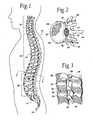
- FIG. 1is a lateral view of a human spinal column
- FIG. 2is a representative coronal view, with portions broken away and in section, of a human vertebral body, which is part of the spinal column shown in FIG. 1;
- FIG. 3is a lateral view, with portions broken away and in section, of several vertebral bodies, which are part of the spinal column shown in FIG. 1;
- FIG. 4is a plan view of a tool which carries at its distal end an expandable structure, which, in use, compresses cancellous bone, the structure being shown in a collapsed condition;
- FIG. 5is enlarged side view of the expandable structure carried by the tool shown in FIG. 4;
- FIG. 6is a coronal view of the vertebral body shown in FIG. 2, with a single tool shown in FIGS. 4 and 5 deployed through a posterolateral access in a collapsed condition;
- FIG. 7is a coronal view of the vertebral body and tool shown in FIG. 6, with the tool in an expanded condition to compress cancellous bone and form a cavity;
- FIG. 8is a coronal view of the vertebral body shown in FIGS. 6 and 7, with the tool removed after formation of the cavity;
- FIG. 9Ais a coronal view of the vertebral body shown in FIG. 8, with the cavity filled with a material that strengthens the vertebral body;
- FIG. 9Bdepicts an alternate method of filling a cavity within a vertebral body
- FIG. 9Cdepicts the vertebral body of FIG. 9B, wherein the cavity is approximately half-filled with material
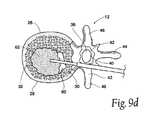
- FIG. 9Ddepicts the vertebral body of FIG. 9B, wherein the cavity is substantially filled with material
- FIGS. 10A to 10 Iare coronal views of a vertebral body, showing tools deployed to create a posterolateral access to compress cancellous bone in a vertebral body to form an interior cavity, which is filled with a material to strengthen the vertebral body;
- FIG. 11Ais a side view of a tool to introduce material into a cavity formed in cancellous bone, with a nozzle having a stepped profile to reduce overall fluid resistance;
- FIG. 11Bis a side view of a tool to introduce material into a cavity formed in cancellous bone, with a nozzle having a tapered profile to reduce overall fluid resistance;
- FIG. 11Cis a side view of a tool to introduce material into a cavity formed in cancellous bone, with a nozzle having a reduced interior profile to reduce overall fluid resistance;
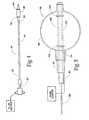
- FIG. 12is an exploded perspective view of a cannula and material introducing device, which embodies features of the invention.
- FIG. 13Ais a cross-sectional side view of one embodiment of a filler instrument constructed in accordance with the teachings of the present invention.
- FIG. 13Bis a side view of the filler instrument of FIG. 13A, taken along line 13 B— 13 B;
- FIG. 14Ais a side view of one embodiment of a first ram assembly constructed in accordance with the teachings of the present invention.
- FIGS. 14B and 14Care side views of the first ram assembly of FIG. 14A;
- FIG. 14Dis a cross-sectional view of the first ram assembly of FIG. 14C, taken along line 14 D— 14 D;
- FIG. 15is a side view of one embodiment of a second ram assembly constructed in accordance with the teachings of the present invention.
- FIGS. 16A through 16Care views of a clip assembly
- FIGS. 17A through 17Dare views of an alternate embodiment of a first ram assembly constructed in accordance with the teachings of the present invention.
- FIG. 18is a side view of an alternate embodiment of a second ram assembly constructed in accordance with the teachings of the present invention.
- FIGS. 19A through 19Dare views of another alternate embodiment of a first ram assembly and filler instrument constructed in accordance with the teachings of the present invention.
- the new systems and methodswill be described with regard to the treatment of vertebral bodies. It should be appreciated, however, the systems and methods so described are not limited in their application to vertebrae. The systems and methods are applicable to the treatment of diverse bone types, including, but not limited to, such bones as the radius, the humerus, the femur, the tibia or the calcanus.
- the spinal column 10comprises a number of uniquely shaped bones, called the vertebrae 12 , a sacrum 14 , and a coccyx 16 (also called the tail bone).
- the number of vertebrae 12 that make up the spinal column 10depends upon the species of animal. In a human (which FIG. 1 shows), there are twenty-four vertebrae 12 , comprising seven cervical vertebrae 18 , twelve thoracic vertebrae 20 , and five lumbar vertebrae 22 .
- the spinal column 10When viewed from the side, as FIG. 1 shows, the spinal column 10 forms an S-shaped curve.
- the curveserves to support the head, which is heavy. In four-footed animals, the curve of the spine is simpler.
- each vertebra 12includes a vertebral body 26 , which extends on the anterior (i.e., front or chest) side of the vertebra 12 .
- the vertebral body 26is in the shape of an oval disk.
- the vertebral body 26includes an exterior formed from compact cortical bone 28 .
- the cortical bone 28encloses an interior volume 30 of reticulated cancellous, or spongy, bone 32 (also called medullary bone or trabecular bone).
- a “cushion,” called an intervertebral disk 34is located between the vertebral bodies 26 .
- the spinal ganglion 39pass through the foramen 36 .
- the spinal cord 38passes through the spinal canal 37 .
- the vertebral arch 40surrounds the spinal canal 37 .
- the pedicle 42 of the vertebral arch 40adjoins the vertebral body 26 .
- the spinous process 44extends from the posterior of the vertebral arch 40 , as do the left and right transverse processes 46 .
- Access to a vertebral bodycan be accomplished from many different directions, depending upon the targeted location within the vertebral body, the intervening anatomy, and the desired complexity of the procedure. For example, access can also be obtained through a pedicle 42 (transpedicular), outside of a pedicle (extrapedicular), along either side of the vertebral body (posterolateral), laterally or anteriorly.
- pedicle 42transpedicular
- extrapedicularoutside of a pedicle
- such approachescan be used with a closed, minimally invasive procedure or with an open procedure.
- FIG. 4shows a tool 48 for preventing or treating compression fracture or collapse of a vertebral body using an expandable body.
- the tool 48includes a catheter tube 50 having a proximal and a distal end, respectively 52 and 54 .
- the distal end 54carries a structure 56 having an expandable exterior wall 58 .
- FIG. 4shows the structure 56 with the wall 58 in a collapsed geometry.
- FIG. 5shows the structure 56 in an expanded geometry.
- FIG. 6shows the collapsed geometry permits insertion of the structure 56 into the interior volume 30 of a targeted vertebral body 26 , as FIG. 6 shows.
- the structure 56can be introduced into the interior volume 30 in various ways.
- FIG. 6shows the insertion of the structure 56 through a single lateral access, which extends through a lateral side of the vertebral body 12 .
- Lateral accessis indicated, for example, if a compression fracture has collapsed the vertebral body 26 below the plane of the pedicle 42 , or for other reasons based upon the preference of the physician. Lateral access can be performed either with a closed, mininimally invasive procedure or with an open procedure. Of course, depending upon the intervening anatomy, well known in the art, lateral access may not be the optimal access path for treatment of vertebrae at all levels of the spine.
- the catheter tube 50includes an interior lumen 80 (see FIG. 4 ).
- the lumen 80is coupled at the proximal end of the catheter tube 50 to a pressurized source of fluid, e.g., saline.
- a syringe containing the fluidcan comprise the pressure source.
- the lumen 80conveys the fluid into the structure 56 under pressure. As a result, the wall 58 expands, as FIGS. 5 and 7 show.
- the fluidis preferably rendered radio-opaque, to facilitate visualization as it enters the structure 56 .
- RenograffinTMcan be used for this purpose.
- expansion of the structure 56can be monitored fluoroscopically or under CT visualization.
- the structure 56may be filled with sterile water, saline solution, or sugar solution, free of a radiopaque material.
- other types of visualizationcould be used, with the tool 48 carrying compatible reference markers.
- the structurecould incorporate a radiopaque material within the material of the structure, or the structure could be painted or “dusted” with a radiopaque material.
- Expansion of the wall 58enlarges the structure 56 , desirably compacting cancellous bone 32 within the interior volume 30 (see FIG. 7) and/or causing desired displacement of cortical bone.
- the compaction of cancellous bone 32forms a cavity 60 in the interior volume 30 of the vertebral body 26 (see FIG. 8 ).
- a filling material 62can be safely and easily introduced into the cavity 60 which the compacted cancellous bone 32 forms.
- expansion of the structure 56desirably forms a region of compacted cancellous bone which substantially surrounds the cavity 60 . This region desirably comprises a physical barrier which limits leakage of the filling material 62 outside the vertebral body 26 .
- the expansion of the structure 56also desirably presses cancellous bone 32 into small fractures which may be present in cortical bone, thereby reducing the possibility of the filling material 62 exiting through the cortical wall.
- the expansion of the structure 56desirably flattens veins in the vertebral body that pass through the cortical wall (e.g., the basivertebral vein), resulting in less opportunity for filling material 62 to extravazate outside the vertebral body through the veinous structure in the cortical wall.
- expansion of the structure 56will compress less dense and/or weaker regions of the cancellous bone, which desirably increases the average density and/or overall strength of the remaining cancellous bone.
- the compaction of cancellous bone by the structure 56can also exert interior force upon cortical bone.
- the structure 56can directly contact the cortical bone, such that expansion and/or manipulation of the structure will cause displacement of the cortical bone. Expansion of the structure 56 within the vertebral body 26 thereby makes it possible to elevate or push broken and compressed bone back to or near its original prefracture position.
- the structure 56is preferably left inflated within the vertebral body 26 for an appropriate waiting period, for example, three to five minutes, to allow some coagulation inside the vertebral body 26 to occur. After the appropriate waiting period, the physician collapses and removes the structure 56 . As FIG. 8 shows, upon removal of the structure 56 , the formed cavity 60 desirably remains in the interior volume 30 .
- the physiciannext introduces a filling material 62 into the formed cavity 60 .
- the filling material 62can comprise a material that resists torsional, tensile, shear and/or compressive forces within the cavity 60 , thereby providing renewed interior structural support for the cortical bone 28 .
- the material 62can comprise a flowable material, such as bone cement, allograft tissue, autograft tissue, or hydroxyapatite, synthetic bone substitute, which is introduced into the cavity 60 and which, in time, sets to a generally hardened condition.
- the material 62can also comprise a compression-resistant material, such as rubber, polyurethane, cyanoacrylate, or silicone rubber, which is inserted into the cavity 60 .
- the material 62can also comprise a semi-solid slurry material (e.g., a bone slurry in a saline base), which is either contained within a porous fabric structure located in the cavity 60 or injected directly into the cavity 60 , to resist compressive forces within the cavity 60 .
- a semi-solid slurry materiale.g., a bone slurry in a saline base
- the material 62could comprise stents, reinforcing bar (Re-Bar) or other types of internal support structures, which desirably resist compressive, tensile, torsional and/or shear forces acting on the bone and/or filler material.
- the filling material 62may also comprise a medication, or a combination of medication and a compression-resistant material, as described above.
- the filling material 62can comprise a bone filling material which does not withstand compressive, tensile, torsional and/or shear forces within the cavity.
- the filling material 62need not be able to immediately bear loads.
- the filling material 62could provide a scaffold for bone growth, or could comprise a material which facilitates or accelerates bone growth, allowing the bone to heal over a period of time.
- the filling materialcould comprise a resorbable or partially-resorbable source of organic or inorganic material for treatment of various bone or non-bone-related disorders including, but not limited to, osteoporosis, cancer, degenerative disk disease, heart disease, acquired immune deficiency syndrome (AIDS) or diabetes.
- the cavity and/or filler materialcould comprise a source of material for treatment of disorders located outside the treated bone.
- the expandable structure 56can be left in the cavity 60 .
- flowable filling material 62is conveyed into the structure 56 , which serves to contain the material 62 .
- the structure 56filled with the material 62 , serves to provide the renewed interior structural support function for the cortical bone 28 .
- the structure 56can be made from an inert, durable, non-degradable plastic material, e.g., polyethylene and other polymers.
- the structure 56can be made from an inert, bio-absorbable material, which degrades over time for absorption or removal by the body.
- the filling material 62itself can serve as the expansion medium for the structure 56 , to compact cancellous bone and form the cavity 60 , to thereby perform both compaction and interior support functions.
- the structure 56can be first expanded with another medium to compact cancellous bone and form the cavity 60 , and the filling material 62 can be subsequently introduced after the expansion medium is removed from structure 56 to provide the interior support function.
- the filling materialcould comprise a two-part material including, but not limited to, settable polymers or calcium alginate. If desired, one part of the filling material could be utilized as the expansion medium, and the second part added after the desired cavity size is achieved.
- the structure 56can be made from a permeable, semi-permeable, or porous material, which allows the transfer of medication contained in the filling material 62 into contact with cancellous bone through the wall of the structure 56 .
- the materialcan comprise a membrane that allows osmotic and/or particulate transfer through the material, or the material can comprise a material that allows the medication to absorb into and/or diffuse through the material.
- medicationcan be transported through a porous wall material by creating a pressure differential across the wall of the structure 56 .
- fluids, cells and/or other materials from the patient's bodycan pass and/or be drawn through the material into the structure for various purposes including, but not limited to, fluid/cellular analysis, bony ingrowth, bone marrow harvesting, and/or gene therapy (including gene replacement therapy).
- a patientlies on an operating table.
- the patientcan lie face down on the table, or on either side, or at an oblique angle, depending upon the physician's preference.
- the physicianFor each access (see FIG. 10 A), the physician introduces a spinal needle assembly 70 into soft tissue ST in the patient's back. Under radiologic or CT monitoring, the physician advances the spinal needle assembly 70 through soft tissue down to and into the targeted vertebral body 26 .
- the physiciancan also employ stereotactic instrumentation to guide advancement of the spinal needle assembly 70 and subsequent tools during the procedure.
- the reference probe for stereotactic guidancecan be inserted through soft tissue and implanted on the surface of the targeted vertebral body.
- the entire procedurecan also be monitored using tools and tags made of non-ferrous materials, e.g., plastic or fiber composites, such as those disclosed in U.S. Pat. Nos. 5,782,764 and 5,744,958, which are each incorporated herein by reference, which would be suitable for use in a computer enhanced, whole-room MRI environment.
- the physicianwill typically administer a local anesthetic, for example, lidocaine, through the assembly 70 .
- a local anestheticfor example, lidocaine
- the physicianmay prefer other forms of anesthesia.
- the physiciandirects the spinal needle assembly 70 to penetrate the cortical bone 28 and the cancellous bone 32 through the side of the vertebral body 26 .
- the depth of penetrationis about 60% to 95% of the vertebral body 26 .
- the physicianholds the stylus 72 and withdraws the stylet 74 of the spinal needle assembly 70 . As FIG. 10B shows, the physician then slides a guide pin instrument 76 through the stylus 72 and into the cancellous bone 32 . The physician now removes the stylus 72 , leaving the guide pin instrument 76 deployed within the cancellous bone 32 .
- the physiciannext slides an obturator instrument 78 over the guide pin instrument 76 , distal end first, as FIG. 10C shows.
- the physiciancan couple the obturator instrument 78 to a handle 80 , which facilitates manipulation of the instrument 78 .
- the physicianmakes a small incision in the patient's back.
- the physiciantwists the handle 80 while applying longitudinal force to the handle 80 .
- the obturator instrument 78rotates and penetrates soft tissue through the incision.
- the physicianmay also gently tap the handle 80 , or otherwise apply appropriate additional longitudinal force to the handle 80 , to advance the obturator instrument 78 through the soft tissue along the guide pin instrument 76 down to the cortical bone entry site.
- the physiciancan also tap the handle 80 with an appropriate striking tool to advance the obturator instrument 78 into a side of the vertebral body 26 to secure its position.
- the obturator instrument 78 shown in FIG. 10Chas an outside diameter that is generally well suited for establishing a lateral access. However, if access is desired through the more narrow region of the vertebral body 26 , e.g., a pedicle 42 (called transpedicular access), the outside diameter of the obturator instrument 78 can be reduced. The reduced diameter of the obturator instrument 78 mediates against damage or breakage of the pedicle 42 . It should be understood that the disclosed methods and devices are well suited for use in conjunction with other approach paths, such as pedicular, extra pedicular, posterolateral and anterior approaches, with varying results.
- the physicianthen proceeds to slide the handle 80 off the obturator instrument 78 and to slide a cannula instrument 84 over the guide pin instrument 76 and, further, over the obturator instrument 78 .
- the physiciancan also couple the handle 80 to the cannula instrument 84 , to apply appropriate twisting and longitudinal forces to rotate and advance the cannula instrument 84 through soft tissue ST over the obturator instrument 78 .
- the physiciancan appropriately tap the handle 80 with a striking tool to advance the end surface into the side of the vertebral body 26 to secure its position.
- the physiciannow withdraws the obturator instrument 78 , sliding it off the guide pin instrument 76 , leaving the guide pin instrument 76 and the cannula instrument 84 in place.
- the physiciancan remove an inner centering sleeve (not shown).
- the physicianslides a drill bit instrument 88 over the guide pin instrument 76 , distal end first, through the cannula instrument 84 , until contact between the machined or cutting edge 90 of the drill bit instrument 88 and cortical bone 28 occurs.
- the physicianthen couples the drill bit instrument 88 to the handle 80 .
- the physicianapplies appropriate twisting and longitudinal forces to the handle 80 , to rotate and advance the machined edge 90 of the drill bit instrument 88 to open a lateral passage PLA through the cortical bone 28 and into the cancellous bone 32 .
- the drilled passage PLApreferably extends no more than 95% across the vertebral body 26 .
- the physicianremoves the drill bit instrument 88 and the guide pin instrument 76 , leaving only the cannula instrument 84 in place, as FIG. 10E shows.
- the passage PLA made by the drill bit instrument 88remains. Subcutaneous lateral access to the cancellous bone 32 has been accomplished.
- the physiciancan fill a syringe 112 with the desired volume of filling material 62 , a batch of which has been previously prepared.
- the cavity volume createdis known. The physician thereby knows the desired volume of material 62 to place in the syringe 112 for each cavity formed in the vertebral body 26 .
- the physicianattaches a nozzle 114 to the filled syringe 112 .
- the physicianthen proceeds to deflate and remove the expandable structure through the associated cannula instrument 84 and to fill the associated cavity with the material 62 .
- the physicianinserts the nozzle 114 through the associated cannula instrument a selected distance into the cavity, guided, e.g., by exterior markings 116 or by real-time fluoroscope or x-ray or MRI visualization.
- the physicianoperates the syringe 112 to cause the material 62 to flow through and out of the nozzle 114 and into the cavity portion.
- the nozzle 114may posses a uniform interior diameter, sized to present a distal end dimension that facilitates insertion into the vertebral body.
- the nozzle 114can possess an interior diameter (e.g., see FIG.
- a tool 160can possess an interior lumen 162 that gradually tapers from a larger interior diameter to a smaller interior diameter.
- a tool 164can possess an interior lumen 166 that steps from a larger to a smaller interior diameter.
- An associated cannula instrument 168may also include a reduced diameter passage, which is downsized to accommodate the reduced diameter tool and to present less flow resistance to filling material conveyed through the cannula instrument.
- the reduced diameter toolmay also be used in association with a vertebroplasty procedure, which injects cement under pressure into a vertebral body, without prior formation of a cavity.
- the filling material 62may contain a predetermined amount of a radiopaque material, e.g., barium or tungsten, sufficient to enable visualization of the flow of material 62 into the cavity portion.
- a radiopaque materiale.g., barium or tungsten
- the amount of radiopaque materialis desirably at least 10%, more desirably at least 20%, and most desirably at least 30%. The physician can thereby visualize the cavity filling process.
- the physicianwithdraws the nozzle 114 from the cavity portion and into the cannula instrument 84 .
- the cannula instrument 84channels the material flow toward the cavity portion. The material flows in a stream into the cavity portion.
- a gasket 122may be provided about the cannula instrument 84 to seal about the access passage PLA.
- the gasket 122serves to prevent leakage of the material about the cannula instrument 84 .
- the physicianoperates the syringe 112 to expel the material 62 through the nozzle 114 , first into the cavity portion and then into the cannula instrument 84 .
- material 62should extend from the cavity and occupy about 40% to 50% of the cannula instrument 84 .
- the physiciancan utilize the syringe 112 to fill the lumen of the nozzle 114 and/or cannula instrument 84 with material 62 , and then utilize a tamping instrument 124 to expel the material from the lumen into the vertebral body.
- the physicianwithdraws the nozzle 114 from the cannula instrument 84 .
- the physicianmay first rotate the syringe 112 and nozzle 114 , to break loose the material 62 in the nozzle 114 from the ejected bolus of material 62 occupying the cannula instrument 84 .
- the physiciannext advances a tamping instrument 124 through the cannula instrument 84 .
- the distal end of the tamping instrument 124contacts the residual volume of material 62 in the cannula instrument 84 .
- Advancement of the tamping instrument 124displaces progressively more of the residual material 62 from the cannula instrument 84 , forcing it into the cavity portion.
- the flow of material 62 into the cavity portion, propelled by the advancement of the tamping instrument 124 in the cannula instrument 84serves to uniformly distribute and compact the material 62 inside the cavity portion, into other cavities and/or openings within the bone, and into fracture lines, without the application of extremely high pressure.
- the use of the syringe 112 , nozzle 114 , and the tamping instrument 124allows the physician to exert precise control when filling the cavity portion with material 62 .
- the physiciancan immediately adjust the volume and rate of delivery according to the particular local physiological conditions encountered.
- the application of low pressure, which is uniformly applied by the syringe 112 and the tamping instrument 124allows the physician to respond to fill volume and flow resistance conditions in a virtually instantaneous fashion. The chance of overfilling and leakage of material 62 outside the cavity portion is significantly reduced.
- FIG. 12depicts a material injection instrument 500 comprising a reduced diameter nozzle 180 and a stylet 182 .
- the stylet 182is desirably sized to pass through the reduced diameter nozzle 180 .
- the nozzle 180is desirably sized to pass through the cannula instrument 184 .
- the nozzle 180can be formed from a substantially rigid metal material, e.g., stainless steel or a high strength plastic.
- the stylet 182includes a handle 192 , which rests on the proximal connector 186 of the nozzle when the stylet 182 is fully inserted into the nozzle 180 .
- the handleWhen the handle is rested, the distal ends of the stylet 182 and nozzle 180 align.
- the presence of the stylet 182 inside the nozzle 180desirably closes the interior bore.
- the nozzle 180can be coupled to the syringe 104 and inserted through the cannula instrument 184 into a material-receiving cavity (not shown) formed within a bone.
- Material 62 in the syringe 104is injected into the nozzle 180 where it desirably passes into the bone.
- the syringe 104may be removed from the nozzle 180 .
- the stylet 182can then be inserted into the nozzle 180 , and advanced through the nozzle, desirably pressurizing the material 62 and pushing it out of the nozzle 180 .
- the stylet 182has a diameter of approximately 0.118 in.
- the cross-sectional area of this stylet 182is approximately 0.010936 in 2
- the nozzle 180desirably contains approximately 1.5 cc of filler material.
- pushing the stylet 182 into the nozzle 180 with a force of force of ten (10) poundscan produce a pressure of approximately 914 lb-in 2 in the filler material 62 within the nozzle 180 .
- the stylet 182has a diameter of approximately 0.136 in. A force of ten (10) pounds utilized on this stylet can produce a pressure of approximately 688 lb-in 2 in the filler material 62 within the nozzle 180 .
- the nozzle 180 and stylet 182can be used in a similar manner as a combination ram 183 to push the filler material 62 through the cannula instrument 184 into the bone.
- the insertion of the ram 183 into the cannula 184will desirably displace the material 62 , forcing the material 62 from the distal end of the cannula 184 into the bone.
- the diameter of the ram 183is approximately 0.143 in.
- pushing the ram 183 with a force of ten (10) poundsis capable of producing a pressure of 622 lb-in 2 in the filler material 62 within the cannula 184 .
- the ram 183acts as a positive displacement “piston” or “pump, ” which permits the physician to accurately gauge the precise amount of filler material 62 that is injected into the bone.
- the filler materialis very viscous, this material will typically strongly resist being pumped through a delivery system. Generally, the greater distance the filler material must travel through the system, the greater the pressure losses will be from such factors as viscosity of the material and frictional losses with the walls. In order to account for these losses, existing delivery systems typically highly pressurize the filler material, often to many thousands of pounds of pressure. Not only does this require stronger pumps and reinforced fittings for the delivery system, but such systems often cannot dispense filler material in very precise amounts. Moreover, if the filler material hardens over time, the system must produce even greater pressures to overcome the increased flow resistance of the material.
- the disclosed systems and methodsobviate and/or reduce the need for complex, high pressure injection systems for delivery of filler materials. Because the disclosed ram 183 travels subcutaneously through the cannula 184 , and displaces filler material 62 out the distal end of the cannula 184 , the amount of filler material being pushed by the ram 183 (and the total amount of filler material 62 within the cannula 184 ) progressively decreases as filler material is injected into the bone. This desirably results in an overall decrease in resistance to movement of the ram during injection. Moreover, because the amount of material being “pushed” by the ram 183 decreases, an increase in the flow resistance of the curing filler material does not necessarily require an increase in injection pressure.
- the filler materialneed only be “pumped ” a short length before it exits the cannula and enters the bone, further reducing the need for extremely high pressures. If injection of additional filler material is required, the ram can be withdrawn from the cannula, additional filler material can be introduced into the cannula, and the process repeated.
- the present arrangementfacilitates injection of even extremely viscous materials under well controlled conditions.
- a wide range of pressurescan be generated in the filler material 62 .
- the disclosed devicescould similarly be used to inject filler material through a spinal needle assembly directly into bone, in a vertebroplasty-like procedure, or can be used to fill a cavity created within the bone.
- the physicianmay choose to continue injecting additional material 62 into the vertebral body.
- this additional materialmay merely increase the volume of the cavity (by further compacting cancellous bone), or may travel into the compressed and/or uncompressed cancellous bone surrounding the cavity, which may serve to further compress cancellous bone and/or further enhance the compressive strength of the vertebral body.
- the physicianwithdraws the tamping instrument 124 from the cannula instrument 84 .
- the physicianpreferably first twists the tamping instrument 124 to cleanly break contact with the material 62 .
- the cannula instrument 84can be withdrawn and the incision site sutured closed.
- FIGS. 9B through 9Ddepict an alternate method of filling a cavity 60 formed within a vertebral body.
- a cannula instrument 84has been advanced through a pedicle 42 of the vertebral body by, providing access to a cavity 60 formed therein.
- a nozzle 180is advanced into the vertebral body, with the distal tip of the nozzle 180 desirably positioned near the anterior side of the cavity 60 .
- Filler material 62is slowly injected through the nozzle 180 into the cavity 60 . As injection of filler material 62 continues, the nozzle 180 is withdrawn towards the center of the cavity 60 . See FIG. 9 c .
- the distal tip of the nozzle 180will remain substantially in contact with the growing bolus of filler material 62 .
- additional filler material 62is injected through the nozzle 180 to substantially fill the cavity 60 .
- the nozzleis then removed from the cavity 60 .
- the nozzlecan be attached to a syringe 104 (see FIG. 12) containing filler material.
- the syringe 104will contain an amount of filler material equal to the volume of the cavity 60 formed within the vertebral body, with the nozzle containing an additional 1.5 cc of filler material.
- the cavity 60will initially be filled with filler material expelled from the syringe 104 .
- the syringe 104can be removed from the nozzle 180 , a stylet 182 inserted into the nozzle 180 , and the remaining filler material within the nozzle 180 pushed by the stylet 182 into the vertebral body.
- the additional filler material from the nozzle 180will extravazate into the cancellous bone, compress additional cancellous bone and/or slightly increase the size of the cavity 60 .
- the disclosed methoddesirably ensures that the cavity is completely filled with filler material. Because the patient is often positioned front side (anterior side) down during the disclosed procedures, the anterior section of the cavity is often the lowest point of the cavity. By initially filling the anterior section of the cavity with filler material, and then filling towards the posterior side of the cavity, fluids and/or suspended solids within the cavity are desirably displaced by the filler material and directed towards the posterior section of the cavity, where they can exit out the cannula. In this manner, “trapping” of fluids within the cavity and/or filler material is avoided and a complete and adequate fill of the vertebral body is ensured.
- the filler materialcan be allowed to harden and/or cure before injection into the vertebral body.
- the filler materialcomprises bone cement, which is allowed to cure to a glue or putty-like state before being injected into the cavity.
- the cementwould desirably have a consistency similar to toothpaste as the cement begins to extrude from the nozzle.
- the selected material 62can also be an autograft or allograft bone graft tissue collected in conventional ways, e.g., in paste form (see Dick, “Use of the Acetabular Reamer to Harvest Autogenic Bone Graft Material: A Simple Method for Producing Bone Paste,” Archives of Orthopaedic and Traumatic Surgery (1986), 105: 235-238), or in pellet form (see Bhan et al, “Percutaneous Bone Grafting for Nonunion and Delayed Union of Fractures of the Tibial Shaft,” International Orthopaedics (SICOT) (1993) 17: 310-312).
- the bone graft tissuecan be obtained using a Bone Graft Harvester, which is commercially available from SpineTech.
- the paste or pellet graft tissue materialis loaded into the cannula instrument 84 30 .
- the tamping instrument 124is then advanced into the cannula instrument 84 in the manner previously described, to displace the paste or pellet graft tissue material out of the cannula instrument 84 and into the cavity portion.
- the selected material 62can also comprise a granular bone material harvested from coral, e.g., ProOstconTM calcium carbonate granules, available from Interpore.
- the granulesare loaded into the cannula instrument 84 using a funnel and advanced into the cavity using the tamping instrument 124 .
- the selected material 62can also comprise demineralized bone matrix suspended in glycerol (e.g., GraftonTM allograft material available from Osteotech), or SRSTM calcium phosphate cement available from Norian.
- demineralized bone matrix suspended in glycerole.g., GraftonTM allograft material available from Osteotech
- SRSTM calcium phosphate cementavailable from Norian.
- the selected material 62can also be in sheet form, e.g. CollagraftTM material made from calcium carbonate powder and collagen from bovine bone.
- the sheetcan be rolled into a tube and loaded by hand into the cannula instrument 84 .
- the tamping instrument 124is then advanced through the cannula instrument 84 , to push and compact the material in the cavity portion.
- FIGS. 13A and 13Bdepict one embodiment of a filler instrument for introducing a desired amount of filling material into a bone or other vertebral body.
- Filler instrument 600comprises a first section 605 and a second section 610 .
- the first and second sections 605 and 610are desirably hollow tubular bodies connected and/or secured in a sealing relationship, with the interior of the first section 605 being in fluid communication with the interior of the second section 610 .
- the first section 605has a first interior cross-sectional area 615
- the second section 610has a second interior cross-sectional area 620
- the first interior cross-sectional area 615will be greater than the second interior cross-sectional area 620
- the first section 605comprises a cylindrical, hollow, tubular member having an interior diameter of 0.358 inches and a length of 2.58 inches
- the second sectioncomprises a cylindrical, hollow, tubular member having an interior diameter of 0.175 inches and a length of 8.84 inches.
- a dispensing opening 640is formed at the distal tip 645 of the second section 610 .
- a first ram opening 650is formed at the proximal end of the first section 605 .
- a flange 655can be formed on the outer portion of the first section 605 .
- the transition from the first section 605 to the second section 610can neck down or taper, as shown in FIG. 13 A.
- FIGS. 14A through 14Ddepict a first ram assembly 700 suitable for use with the described filler instrument 600 .
- the first ram assembly 700comprises a first plunger 705 sized to pass through the interior of the first section 605 .
- a seal 710such as an O-ring, is secured to the distal end 715 of the first plunger 705 in a manner well known in the art.
- the seal 710will slidingly engage with the inner walls of the first section 605 to seal the proximal end of the first section 605 as the first plunger 705 advances therethrough.
- the seal 710will comprise Teflon, natural rubber, or other type of sealant material.
- the cross-section of the disclosed plungeris circular (see FIG. 14 B), plungers having other cross-sectional shapes, such as triangular or rectangular shapes, could similarly be utilized with varying results.
- a ram flange 725can be formed on the distal portion of the first plunger 705 .
- the ram flange 725will abut and/or contact the flange 655 when the distal end of the first plunger 700 reaches a desired position near or abutting the distal end of the first section 605 .
- the first ram assembly 700further comprises a second ram opening 720 extending longitudinally through the first plunger 705 .
- the size and shape of the cross-sectional area of the second ram opening 720will be less than or approximate the size and shape of the second interior cross-sectional area 620 .
- the first ram assembly 700is 2.62 inches long, the first plunger 705 having an outer diameter of 0.357 inches, and the inner diameter of the second ram opening 720 is 0.115 inches.
- FIG. 15depicts a second ram assembly 750 suitable for use with the first ram assembly 700 and the filler instrument 600 .
- the second ram assembly 750comprises a second plunger 755 , and a knob 760 secured to the proximal end of the second plunger 755 .
- the second plunger 755is desirably sized to pass through the second ram opening 720 and the second section 610 .
- the second ram assemblyfurther comprises a notch 765 .
- a retaining clip 800(see FIGS. 16A through 16C) desirably releasably secures the second ram assembly 750 within the second ram opening 720 .
- the second ram assembly 750is 11.8 inches long, the second plunger 755 has an outer diameter of 0.113 inches, and the notch 765 is located approximately 2.62 inches from the distal tip of the second plunger 755 .
- the various components of the filler instrument 600can comprise a substantially rigid metal, plastic or ceramic material, e.g., stainless steel or a high strength plastic.
- the filler instrument 600 and second ram assemblycomprise 303 stainless steel, and the first ram assembly comprises Delrin® plastic (available commercially from DuPont Corporation).
- the filler instrument 600When injection of filler material is desired, the filler instrument 600 is filled with filler material (not shown) such as bone cement or PMMA.
- filler materialsuch as bone cement or PMMA.
- the second ram assembly 750is secured within the first ram assembly with the retaining clip 800 .
- the distal end 715 of the first plunger 705is then inserted into the first ram opening 650 .
- filler material in the first section 605is displaced by the plunger 705 , which in turn forces material in the second section 610 out through the dispensing opening 640 .
- Passage of a significant amount of filler material through the second ram opening 720is prevented by the presence of the second plunger 755 , which is desirably held in position by the retaining clip 800 .
- the distal end 715 approaches the distal end of the first section 605desirably substantially all of the filler material will be displaced from the first section 605 into the second section 610 and/or out the dispensing opening 640 .
- the retaining clip 800is then released, and the second plunger 755 advanced through the distal end of the first section 605 and into the second section 610 .
- the shape and size of the cross-sectional area of the second plunger 755will approximate the shape and size of the cross-sectional area 620 of the second section 610 , such that the second plunger 755 displaces substantially all of the filler material in the second section 610 as the second plunger 755 advances.
- substantially all of the filler material within the first and second sections 605 and 610will be dispensed from the filler instrument 600 .
- the present inventionfacilitates dispensing of a substantial amount of filler material from a single filler instrument. Because the viscosity of PMMA and various other types of filler materials typically increases with time during the dispensing process, it becomes progressively harder to dispense filler material over time. By utilizing a plunger of larger cross-sectional area to initiate the filling operation, when the filler material is less viscous, the present invention allows dispensing of a significant amount of filler material.
- the reduced cross-sectional area of the second plungerallows continued dispensing of the more viscous filler material, even when it is in a highly viscous state.
- the second sectionis of reduced cross-sectional area, its reduced profile will desirably allow the distal tip of the filler instrument to be introduced through the cannula and/or soft tissues and directly into the targeted vertebral body, while still providing a sufficient reservoir of filler material to accomplish the goals of augmenting and/or repairing the targeted bone.
- the toolneed not be refilled and/or “switched out” during the dispensing operation, but can rather remain in place and dispense the entire required amount of bone filler for the procedure, the potential for trapping air within the vertebral body and/or bolus of cement is significantly reduced.
- the present inventionalso greatly facilitates the ability of the physician to immediately shift from a higher volume, lower pressure cement flow to a lower volume, higher pressure cement flow.
- the physicianmay determine that a more controlled, higher pressure and/or lower volume flow of cement is needed.
- the cementmay cure or harden to a point where further movement of the first plunger is extremely difficult and/or impossible to effect one embodiment of the present invention permits the physician to advance the second plunger into the second section, even when the distal end of the first plunger is not near and/or abutting the distal end of the first section.
- the second plungerpasses through the cement in the first section, and enters the second section, cement will be displaced from the second section. Due to the decreased cross-sectional area of the second plunger and second section (as compared to the first plunger and first section), the second plunger is easier to push through the cement in the first section and cement can more easily be dispensed from the second section at higher pressures and/or lower volumes.
- the disclosed filler instrumentmay be used to introduce filler material through a cannula into a cavity created within a bone, or may be used with vertebroplasty-type techniques to introduce filler material directly into the vertebral body without prior formation of a cavity. Where prior cavity-formation is not required and/or desired, and vertebroplasty-like techniques will be used, the filler instrument can incorporate a needle-point at the distal end of the instrument, or the diameter of the second section can be significantly reduced to allow passage of the instrument through the lumen of a spinal needle assembly.
- one or more of the sections of the filler instrumentcould comprise a commercially available spinal needle assembly (such as a Bone Marrow Biopsy Needle No. 508627, available from Becton Dickinson & Co., Franklin Lakes, N.J., 07417). If desired, one or more plunger assemblies of varying sizes and lengths could be provided to accommodate differing spinal needle assemblies.
- the filler instrumentcan be pre-loaded with filler material, introduced through soft tissues and into the vertebral body, used to inject filler material, and removed, quickly and easily without need for tool exchanges during the operation.
- filler materialintroduced through soft tissues and into the vertebral body, used to inject filler material, and removed, quickly and easily without need for tool exchanges during the operation.
- bone cementcan be injected under pressure through a needle directly into the cancellous bone of the vertebral body (without cavity formation). The bone cement penetrates cancellous bone.
- the filler instrumentcan possess an increasing interior diameter, as shown in FIGS. 11A, 11 B, or 11 C.
- the reduced flow resistancewould make possible the use of more viscous cement, to thereby further reduce the possibility that the cement would exude from the vertebral body.
- FIGS. 17A through 17D and FIG. 18depict an alternate embodiment of a filler instrument constructed in accordance with the teachings of the present invention. Because many of the features of this embodiment are similar to those previously described, like reference numerals will be used to describe similar components.
- the first ram assembly 700 Afurther comprises an increased cross-sectional tip opening 850 within the distal end 715 A of the assembly 700 A. This tip opening 850 corresponds to a increased cross-sectional plunger tip 855 on the second plunger 755 .
- the plunger tip 855seats within the tip opening 850 , desirably preventing the second plunger 750 A from moving axially in response to the increased pressure of the filler material.
- a clip(not shown) can be utilized to secure the second plunger to the first plunger. Once the first plunger 705 A has been advanced to its desired position, the clip (not shown) can be removed from the notch 765 A, and the second plunger 750 A advanced as previously described.
- FIGS. 19A through 19Ddepict another alternate embodiment of a filler instrument 600 B constructed in accordance with the teachings of the present invention. Because many of the features of this embodiment are similar to those previously described, like reference numerals will be used to describe similar components.
- the first ram assembly 700 Bcomprises a check valve 900 located at the distal tip 715 of the assembly 700 B.
- the check valve 900will desirably prevent filler material from travelling through the second ram opening 755 B as the first plunger 705 B is advanced.
- the check valve 900permits passage of the second plunger into the first and second sections as previously described.
Landscapes
- Health & Medical Sciences (AREA)
- Life Sciences & Earth Sciences (AREA)
- Orthopedic Medicine & Surgery (AREA)
- Surgery (AREA)
- Public Health (AREA)
- Engineering & Computer Science (AREA)
- Biomedical Technology (AREA)
- Heart & Thoracic Surgery (AREA)
- Animal Behavior & Ethology (AREA)
- General Health & Medical Sciences (AREA)
- Veterinary Medicine (AREA)
- Medical Informatics (AREA)
- Molecular Biology (AREA)
- Nuclear Medicine, Radiotherapy & Molecular Imaging (AREA)
- Oral & Maxillofacial Surgery (AREA)
- Dentistry (AREA)
- Transplantation (AREA)
- Cardiology (AREA)
- Vascular Medicine (AREA)
- Physical Education & Sports Medicine (AREA)
- Physics & Mathematics (AREA)
- Fluid Mechanics (AREA)
- Neurology (AREA)
- Anesthesiology (AREA)
- Hematology (AREA)
- Prostheses (AREA)
- Surgical Instruments (AREA)
- Materials For Medical Uses (AREA)
- Medicines Containing Material From Animals Or Micro-Organisms (AREA)
- Processing Of Meat And Fish (AREA)
- Accessories And Tools For Shearing Machines (AREA)
- Processing And Handling Of Plastics And Other Materials For Molding In General (AREA)
- Dental Tools And Instruments Or Auxiliary Dental Instruments (AREA)
Abstract
Description
Claims (14)
Priority Applications (3)
| Application Number | Priority Date | Filing Date | Title |
|---|---|---|---|
| US09/905,170US6641587B2 (en) | 1998-08-14 | 2001-07-13 | Systems and methods for treating vertebral bodies |
| US10/640,790US7252671B2 (en) | 1998-08-14 | 2003-08-14 | Systems and methods for treating vertebral bodies |
| US11/890,594US20070282346A1 (en) | 1998-08-14 | 2007-08-07 | Systems and methods for treating vertebral bodies |
Applications Claiming Priority (3)
| Application Number | Priority Date | Filing Date | Title |
|---|---|---|---|
| US09/134,323US6241734B1 (en) | 1998-08-14 | 1998-08-14 | Systems and methods for placing materials into bone |
| US21823700P | 2000-07-14 | 2000-07-14 | |
| US09/905,170US6641587B2 (en) | 1998-08-14 | 2001-07-13 | Systems and methods for treating vertebral bodies |
Related Parent Applications (2)
| Application Number | Title | Priority Date | Filing Date |
|---|---|---|---|
| US09/134,323Continuation-In-PartUS6241734B1 (en) | 1994-01-26 | 1998-08-14 | Systems and methods for placing materials into bone |
| US09/597,646Continuation-In-PartUS6716216B1 (en) | 1994-01-26 | 2000-06-20 | Systems and methods for treating vertebral bodies |
Related Child Applications (1)
| Application Number | Title | Priority Date | Filing Date |
|---|---|---|---|
| US10/640,790DivisionUS7252671B2 (en) | 1998-08-14 | 2003-08-14 | Systems and methods for treating vertebral bodies |
Publications (2)
| Publication Number | Publication Date |
|---|---|
| US20020099384A1 US20020099384A1 (en) | 2002-07-25 |
| US6641587B2true US6641587B2 (en) | 2003-11-04 |
Family
ID=22814303
Family Applications (3)
| Application Number | Title | Priority Date | Filing Date |
|---|---|---|---|
| US09/905,170Expired - Fee RelatedUS6641587B2 (en) | 1998-08-14 | 2001-07-13 | Systems and methods for treating vertebral bodies |
| US10/640,790Expired - Fee RelatedUS7252671B2 (en) | 1998-08-14 | 2003-08-14 | Systems and methods for treating vertebral bodies |
| US11/890,594AbandonedUS20070282346A1 (en) | 1998-08-14 | 2007-08-07 | Systems and methods for treating vertebral bodies |
Family Applications After (2)
| Application Number | Title | Priority Date | Filing Date |
|---|---|---|---|
| US10/640,790Expired - Fee RelatedUS7252671B2 (en) | 1998-08-14 | 2003-08-14 | Systems and methods for treating vertebral bodies |
| US11/890,594AbandonedUS20070282346A1 (en) | 1998-08-14 | 2007-08-07 | Systems and methods for treating vertebral bodies |
Country Status (10)
| Country | Link |
|---|---|
| US (3) | US6641587B2 (en) |
| EP (1) | EP1303236B1 (en) |
| JP (1) | JP4809572B2 (en) |
| KR (1) | KR20030029621A (en) |
| CN (2) | CN100486536C (en) |
| AT (1) | ATE415915T1 (en) |
| AU (1) | AU2001277885A1 (en) |
| CA (1) | CA2415389C (en) |
| DE (1) | DE60136815D1 (en) |
| WO (1) | WO2002017801A2 (en) |
Cited By (153)
| Publication number | Priority date | Publication date | Assignee | Title |
|---|---|---|---|---|
| US20040049203A1 (en)* | 1998-08-14 | 2004-03-11 | Kyphon Inc. | Systems and methods for treating vertebral bodies |
| US20040054414A1 (en)* | 2002-09-18 | 2004-03-18 | Trieu Hai H. | Collagen-based materials and methods for augmenting intervertebral discs |
| US20040102721A1 (en)* | 2002-11-22 | 2004-05-27 | Mckinley Laurence M. | System, method and apparatus for locating, measuring and evaluating the enlargement of a foramen |
| US20050031578A1 (en)* | 2002-03-22 | 2005-02-10 | Doctor's Research Group, Inc. | Methods of performing medical procedures which promote bone growth, compositions which promote bone growth, and methods of making such compositions |
| US6923813B2 (en) | 2003-09-03 | 2005-08-02 | Kyphon Inc. | Devices for creating voids in interior body regions and related methods |
| WO2005077443A1 (en)* | 2004-02-18 | 2005-08-25 | Mcgill University | A device for injecting a viscous material into a hard tissue |
| US20050209601A1 (en)* | 2004-03-22 | 2005-09-22 | Disc Dynamics, Inc. | Multi-stage biomaterial injection system for spinal implants |
| US20050220771A1 (en)* | 2002-03-22 | 2005-10-06 | Doctor's Research Group, Inc. | Methods of performing medical procedures that promote bone growth, methods of making compositions that promote bone growth, and apparatus for use in such methods |
| US20060068362A1 (en)* | 2004-09-27 | 2006-03-30 | Ormco Corporation | Endodontic instrument with depth markers |
| US20060085074A1 (en)* | 2004-10-18 | 2006-04-20 | Kamshad Raiszadeh | Medical device systems for the spine |
| US20060106461A1 (en)* | 2004-11-12 | 2006-05-18 | Embry Jill M | Implantable vertebral lift |
| US20060115462A1 (en)* | 2004-12-01 | 2006-06-01 | Vladimir Subbotin | Direct DNA delivery to bone cells |
| US20060184192A1 (en)* | 2005-02-11 | 2006-08-17 | Markworth Aaron D | Systems and methods for providing cavities in interior body regions |
| US20060265076A1 (en)* | 2005-05-03 | 2006-11-23 | Disc Dynamics, Inc. | Catheter holder for spinal implant |
| US20070010845A1 (en)* | 2005-07-08 | 2007-01-11 | Gorman Gong | Directionally controlled expandable device and methods for use |
| US20070006692A1 (en)* | 2005-07-11 | 2007-01-11 | Phan Christopher U | Torque limiting device |
| US20070010844A1 (en)* | 2005-07-08 | 2007-01-11 | Gorman Gong | Radiopaque expandable body and methods |
| US20070010824A1 (en)* | 2005-07-11 | 2007-01-11 | Hugues Malandain | Products, systems and methods for delivering material to bone and other internal body parts |
| US20070010848A1 (en)* | 2005-07-11 | 2007-01-11 | Andrea Leung | Systems and methods for providing cavities in interior body regions |
| US20070055276A1 (en)* | 2005-07-11 | 2007-03-08 | Edidin Avram A | Systems and methods for inserting biocompatible filler materials in interior body regions |
| US20070055282A1 (en)* | 2003-03-31 | 2007-03-08 | The Cleveland Clinic Foundation | Apparatus and method for harvesting bone marrow |
| US20070055201A1 (en)* | 2005-07-11 | 2007-03-08 | Seto Christine L | Systems and methods for providing cavities in interior body regions |
| US20070060933A1 (en)* | 2005-07-11 | 2007-03-15 | Meera Sankaran | Curette heads |
| WO2007008333A3 (en)* | 2005-07-07 | 2007-03-29 | Kyphon Inc | Balloon assisted apparatus and method for accessing an intervertebral disc |
| US20070118142A1 (en)* | 2005-11-18 | 2007-05-24 | Krueger John A | Device, system and method for delivering a curable material into bone |
| US20070129669A1 (en)* | 2003-05-21 | 2007-06-07 | Crosstrees Medical, Inc. | Extractable filler for inserting medicine into animal tissue |
| US20070129670A1 (en)* | 2003-09-29 | 2007-06-07 | Crosstrees Medical, Inc. | Extractable filler for inserting medicine into vertebral body |
| US20070142765A1 (en)* | 2003-05-21 | 2007-06-21 | Crosstrees Medical, Inc. | Extractable filler for inserting medicine into animal tissue |
| US20070142842A1 (en)* | 2005-11-18 | 2007-06-21 | Krueger John A | Device, system and method for delivering a curable material into bone |
| US20070233258A1 (en)* | 2006-02-28 | 2007-10-04 | Zimmer Spine, Inc. | Vertebroplasty- device and method |
| US20070233149A1 (en)* | 2004-02-06 | 2007-10-04 | Dr. H. C. Robert Mathys Stiftung | Injection Device, Especially for Bone Cement |
| US20070260227A1 (en)* | 2005-07-11 | 2007-11-08 | Phan Christopher U | Axial load limiting system and methods |
| US20080009876A1 (en)* | 2006-07-07 | 2008-01-10 | Meera Sankaran | Medical device with expansion mechanism |
| US20080058931A1 (en)* | 2006-07-21 | 2008-03-06 | John White | Expandable vertebral implant and methods of use |
| US20080058954A1 (en)* | 2006-08-22 | 2008-03-06 | Hai Trieu | Methods of treating spinal injuries using injectable flowable compositions comprising organic materials |
| US20080086142A1 (en)* | 2006-10-06 | 2008-04-10 | Kohm Andrew C | Products and Methods for Delivery of Material to Bone and Other Internal Body Parts |
| US20080167726A1 (en)* | 2007-01-08 | 2008-07-10 | Warsaw Orthopedic, Inc. | Expandable containment devices and methods |
| US20080243249A1 (en)* | 2007-03-30 | 2008-10-02 | Kohm Andrew C | Devices for multipoint emplacement in a body part and methods of use of such devices |
| US20080245972A1 (en)* | 2007-04-06 | 2008-10-09 | Warsaw Orthopedic, Inc. | System and Method for Patient Balance and Position Analysis |
| US7465318B2 (en) | 2004-04-15 | 2008-12-16 | Soteira, Inc. | Cement-directing orthopedic implants |
| US20090036799A1 (en)* | 2007-03-30 | 2009-02-05 | Medtronic Spinal And Biologics Business | Methods and Systems For The Diagnosis and Treatment of Medical Conditions in the Spine and Other Body Parts |
| US7520888B2 (en) | 2006-02-14 | 2009-04-21 | Warsaw Orthopedic, Inc. | Treatment of the vertebral column |
| US7524103B2 (en) | 2003-11-18 | 2009-04-28 | Boston Scientific Scimed, Inc. | Apparatus for mixing and dispensing a multi-component bone cement |
| US20090149860A1 (en)* | 2005-07-07 | 2009-06-11 | Scribner Robert M | Device for delivery of bone void filling materials |
| US7575577B2 (en)* | 2001-11-01 | 2009-08-18 | Spinewave | Devices and methods for the restoration of a spinal disc |
| US20090254132A1 (en)* | 2005-07-07 | 2009-10-08 | Scribner Robert M | Devices and methods for the treatment of bone fracture |
| US7601157B2 (en)* | 2001-11-01 | 2009-10-13 | Spine Wave, Inc. | Devices and methods for the restoration of a spinal disc |
| US7641664B2 (en) | 2004-02-12 | 2010-01-05 | Warsaw Orthopedic, Inc. | Surgical instrumentation and method for treatment of a spinal structure |
| US7666226B2 (en) | 2005-08-16 | 2010-02-23 | Benvenue Medical, Inc. | Spinal tissue distraction devices |
| US7731981B2 (en) | 2002-11-15 | 2010-06-08 | Warsaw Orthopedic, Inc. | Collagen-based materials and methods for treating synovial joints |
| US20100160921A1 (en)* | 2008-12-19 | 2010-06-24 | Arthrocare Corporation | Cancellous bone displacement system and methods of use |
| US7744651B2 (en) | 2002-09-18 | 2010-06-29 | Warsaw Orthopedic, Inc | Compositions and methods for treating intervertebral discs with collagen-based materials |
| US7749230B2 (en) | 2004-09-02 | 2010-07-06 | Crosstrees Medical, Inc. | Device and method for distraction of the spinal disc space |
| US20110054416A1 (en)* | 2007-09-14 | 2011-03-03 | Hollowell Daniel R | Material control device for inserting material into a targeted anatomical region |
| US7909873B2 (en) | 2006-12-15 | 2011-03-22 | Soteira, Inc. | Delivery apparatus and methods for vertebrostenting |
| US20110112507A1 (en)* | 2009-11-10 | 2011-05-12 | Carefusion 207, Inc. | Curable material delivery systems and methods |
| US20110190776A1 (en)* | 2009-12-18 | 2011-08-04 | Palmaz Scientific, Inc. | Interosteal and intramedullary implants and method of implanting same |
| US8016834B2 (en) | 2005-08-03 | 2011-09-13 | Helmut Weber | Process and device for treating vertebral bodies |
| US8038682B2 (en) | 2004-08-17 | 2011-10-18 | Boston Scientific Scimed, Inc. | Apparatus and methods for delivering compounds into vertebrae for vertebroplasty |
| US8066713B2 (en) | 2003-03-31 | 2011-11-29 | Depuy Spine, Inc. | Remotely-activated vertebroplasty injection device |
| US8105236B2 (en) | 2005-07-11 | 2012-01-31 | Kyphon Sarl | Surgical access device, system, and methods of use |
| US8118779B2 (en) | 2006-06-30 | 2012-02-21 | Warsaw Orthopedic, Inc. | Collagen delivery device |
| US8126736B2 (en) | 2009-01-23 | 2012-02-28 | Warsaw Orthopedic, Inc. | Methods and systems for diagnosing, treating, or tracking spinal disorders |
| US8128632B2 (en) | 2006-05-22 | 2012-03-06 | Orthovita, Inc. | Delivery of multicomponent compositions |
| US8142462B2 (en) | 2004-05-28 | 2012-03-27 | Cavitech, Llc | Instruments and methods for reducing and stabilizing bone fractures |
| US20120109139A1 (en)* | 2010-10-29 | 2012-05-03 | Kyphon Sarl | Reduced extravasation of bone cement |
| US8221420B2 (en) | 2009-02-16 | 2012-07-17 | Aoi Medical, Inc. | Trauma nail accumulator |
| US8226657B2 (en) | 2009-11-10 | 2012-07-24 | Carefusion 207, Inc. | Systems and methods for vertebral or other bone structure height restoration and stabilization |
| US8277506B2 (en) | 2008-06-24 | 2012-10-02 | Carefusion 2200, Inc. | Method and structure for stabilizing a vertebral body |
| US8287915B2 (en) | 2004-02-03 | 2012-10-16 | Orthovita, Inc. | Bone restorative carrier mediums |
| USD669168S1 (en) | 2005-11-18 | 2012-10-16 | Carefusion 2200, Inc. | Vertebral augmentation needle |
| US8303967B2 (en) | 2006-06-29 | 2012-11-06 | Orthovita, Inc. | Bioactive bone graft substitute |
| US8353911B2 (en) | 2007-05-21 | 2013-01-15 | Aoi Medical, Inc. | Extendable cutting member |
| US8360629B2 (en) | 2005-11-22 | 2013-01-29 | Depuy Spine, Inc. | Mixing apparatus having central and planetary mixing elements |
| US8361078B2 (en) | 2003-06-17 | 2013-01-29 | Depuy Spine, Inc. | Methods, materials and apparatus for treating bone and other tissue |
| US8366773B2 (en) | 2005-08-16 | 2013-02-05 | Benvenue Medical, Inc. | Apparatus and method for treating bone |
| US8399619B2 (en) | 2006-06-30 | 2013-03-19 | Warsaw Orthopedic, Inc. | Injectable collagen material |
| US8415407B2 (en) | 2004-03-21 | 2013-04-09 | Depuy Spine, Inc. | Methods, materials, and apparatus for treating bone and other tissue |
| US8454617B2 (en) | 2005-08-16 | 2013-06-04 | Benvenue Medical, Inc. | Devices for treating the spine |
| US8535327B2 (en) | 2009-03-17 | 2013-09-17 | Benvenue Medical, Inc. | Delivery apparatus for use with implantable medical devices |
| US8535380B2 (en) | 2010-05-13 | 2013-09-17 | Stout Medical Group, L.P. | Fixation device and method |
| US8579908B2 (en) | 2003-09-26 | 2013-11-12 | DePuy Synthes Products, LLC. | Device for delivering viscous material |
| US8591583B2 (en) | 2005-08-16 | 2013-11-26 | Benvenue Medical, Inc. | Devices for treating the spine |
| US8685093B2 (en) | 2009-01-23 | 2014-04-01 | Warsaw Orthopedic, Inc. | Methods and systems for diagnosing, treating, or tracking spinal disorders |
| US8685429B2 (en) | 1999-08-13 | 2014-04-01 | Orthovita, Inc. | Shaped bodies and methods for their production and use |
| US8690884B2 (en) | 2005-11-18 | 2014-04-08 | Carefusion 2200, Inc. | Multistate-curvature device and method for delivering a curable material into bone |
| US8709042B2 (en) | 2004-09-21 | 2014-04-29 | Stout Medical Group, LP | Expandable support device and method of use |
| US8771276B2 (en) | 2010-12-01 | 2014-07-08 | Carefusion 2200, Inc. | Systems and methods for forming a cavity in, and delivering curable material into, bone |
| US8814873B2 (en) | 2011-06-24 | 2014-08-26 | Benvenue Medical, Inc. | Devices and methods for treating bone tissue |
| US8827981B2 (en) | 2007-11-16 | 2014-09-09 | Osseon Llc | Steerable vertebroplasty system with cavity creation element |
| US20140309646A1 (en)* | 2010-11-12 | 2014-10-16 | Smith & Nephew, Inc. | Inflatable, steerable balloon for elevation of tissue within a body |
| US8894658B2 (en) | 2009-11-10 | 2014-11-25 | Carefusion 2200, Inc. | Apparatus and method for stylet-guided vertebral augmentation |
| US8900620B2 (en) | 2005-10-13 | 2014-12-02 | DePuy Synthes Products, LLC | Drug-impregnated encasement |
| US8950929B2 (en) | 2006-10-19 | 2015-02-10 | DePuy Synthes Products, LLC | Fluid delivery system |
| US8992541B2 (en) | 2003-03-14 | 2015-03-31 | DePuy Synthes Products, LLC | Hydraulic device for the injection of bone cement in percutaneous vertebroplasty |
| US8998923B2 (en) | 2005-08-31 | 2015-04-07 | Spinealign Medical, Inc. | Threaded bone filling material plunger |
| US9050112B2 (en) | 2011-08-23 | 2015-06-09 | Flexmedex, LLC | Tissue removal device and method |
| US9095393B2 (en) | 2012-05-30 | 2015-08-04 | Carefusion 2200, Inc. | Method for balloon-aided vertebral augmentation |
| US9119639B2 (en) | 2011-08-09 | 2015-09-01 | DePuy Synthes Products, Inc. | Articulated cavity creator |
| US9149286B1 (en) | 2010-11-12 | 2015-10-06 | Flexmedex, LLC | Guidance tool and method for use |
| US9192397B2 (en) | 2006-12-15 | 2015-11-24 | Gmedelaware 2 Llc | Devices and methods for fracture reduction |
| US9220554B2 (en) | 2010-02-18 | 2015-12-29 | Globus Medical, Inc. | Methods and apparatus for treating vertebral fractures |
| US9220595B2 (en) | 2004-06-23 | 2015-12-29 | Orthovita, Inc. | Shapeable bone graft substitute and instruments for delivery thereof |
| US9326806B2 (en) | 2003-09-02 | 2016-05-03 | Crosstrees Medical, Inc. | Devices and methods for the treatment of bone fracture |
| US9381683B2 (en) | 2011-12-28 | 2016-07-05 | DePuy Synthes Products, Inc. | Films and methods of manufacture |
| US9381024B2 (en) | 2005-07-31 | 2016-07-05 | DePuy Synthes Products, Inc. | Marked tools |
| US9439693B2 (en) | 2013-02-01 | 2016-09-13 | DePuy Synthes Products, Inc. | Steerable needle assembly for use in vertebral body augmentation |
| US9480485B2 (en) | 2006-12-15 | 2016-11-01 | Globus Medical, Inc. | Devices and methods for vertebrostenting |
| US9510885B2 (en) | 2007-11-16 | 2016-12-06 | Osseon Llc | Steerable and curvable cavity creation system |
| US9642932B2 (en) | 2006-09-14 | 2017-05-09 | DePuy Synthes Products, Inc. | Bone cement and methods of use thereof |
| US9770339B2 (en) | 2005-07-14 | 2017-09-26 | Stout Medical Group, L.P. | Expandable support device and method of use |
| US9788963B2 (en) | 2003-02-14 | 2017-10-17 | DePuy Synthes Products, Inc. | In-situ formed intervertebral fusion device and method |
| US9918767B2 (en) | 2005-08-01 | 2018-03-20 | DePuy Synthes Products, Inc. | Temperature control system |
| US10070968B2 (en) | 2010-08-24 | 2018-09-11 | Flexmedex, LLC | Support device and method for use |
| US10085783B2 (en) | 2013-03-14 | 2018-10-02 | Izi Medical Products, Llc | Devices and methods for treating bone tissue |
| US10231846B2 (en) | 2016-08-19 | 2019-03-19 | Stryker European Holdings I, Llc | Bone graft delivery loading assembly |
| US10285820B2 (en) | 2008-11-12 | 2019-05-14 | Stout Medical Group, L.P. | Fixation device and method |
| US10463380B2 (en) | 2016-12-09 | 2019-11-05 | Dfine, Inc. | Medical devices for treating hard tissues and related methods |
| US10478241B2 (en) | 2016-10-27 | 2019-11-19 | Merit Medical Systems, Inc. | Articulating osteotome with cement delivery channel |
| US10500304B2 (en) | 2013-06-21 | 2019-12-10 | DePuy Synthes Products, Inc. | Films and methods of manufacture |
| US10624652B2 (en) | 2010-04-29 | 2020-04-21 | Dfine, Inc. | System for use in treatment of vertebral fractures |
| US10660656B2 (en) | 2017-01-06 | 2020-05-26 | Dfine, Inc. | Osteotome with a distal portion for simultaneous advancement and articulation |
| US10758289B2 (en) | 2006-05-01 | 2020-09-01 | Stout Medical Group, L.P. | Expandable support device and method of use |
| US10888433B2 (en) | 2016-12-14 | 2021-01-12 | DePuy Synthes Products, Inc. | Intervertebral implant inserter and related methods |
| US10940014B2 (en) | 2008-11-12 | 2021-03-09 | Stout Medical Group, L.P. | Fixation device and method |
| US10940016B2 (en) | 2017-07-05 | 2021-03-09 | Medos International Sarl | Expandable intervertebral fusion cage |
| US10966840B2 (en) | 2010-06-24 | 2021-04-06 | DePuy Synthes Products, Inc. | Enhanced cage insertion assembly |
| US10973652B2 (en) | 2007-06-26 | 2021-04-13 | DePuy Synthes Products, Inc. | Highly lordosed fusion cage |
| US11026744B2 (en) | 2016-11-28 | 2021-06-08 | Dfine, Inc. | Tumor ablation devices and related methods |
| US11197681B2 (en) | 2009-05-20 | 2021-12-14 | Merit Medical Systems, Inc. | Steerable curvable vertebroplasty drill |
| US11273050B2 (en) | 2006-12-07 | 2022-03-15 | DePuy Synthes Products, Inc. | Intervertebral implant |
| US11344424B2 (en) | 2017-06-14 | 2022-05-31 | Medos International Sarl | Expandable intervertebral implant and related methods |
| US11426290B2 (en) | 2015-03-06 | 2022-08-30 | DePuy Synthes Products, Inc. | Expandable intervertebral implant, system, kit and method |
| US11426286B2 (en) | 2020-03-06 | 2022-08-30 | Eit Emerging Implant Technologies Gmbh | Expandable intervertebral implant |
| US11446155B2 (en) | 2017-05-08 | 2022-09-20 | Medos International Sarl | Expandable cage |
| US11446156B2 (en) | 2018-10-25 | 2022-09-20 | Medos International Sarl | Expandable intervertebral implant, inserter instrument, and related methods |
| US11452607B2 (en) | 2010-10-11 | 2022-09-27 | DePuy Synthes Products, Inc. | Expandable interspinous process spacer implant |
| US11497619B2 (en) | 2013-03-07 | 2022-11-15 | DePuy Synthes Products, Inc. | Intervertebral implant |
| US11510723B2 (en) | 2018-11-08 | 2022-11-29 | Dfine, Inc. | Tumor ablation device and related systems and methods |
| US11510788B2 (en) | 2016-06-28 | 2022-11-29 | Eit Emerging Implant Technologies Gmbh | Expandable, angularly adjustable intervertebral cages |
| US11596523B2 (en) | 2016-06-28 | 2023-03-07 | Eit Emerging Implant Technologies Gmbh | Expandable and angularly adjustable articulating intervertebral cages |
| US11602438B2 (en) | 2008-04-05 | 2023-03-14 | DePuy Synthes Products, Inc. | Expandable intervertebral implant |
| US11607321B2 (en) | 2009-12-10 | 2023-03-21 | DePuy Synthes Products, Inc. | Bellows-like expandable interbody fusion cage |
| US11612491B2 (en) | 2009-03-30 | 2023-03-28 | DePuy Synthes Products, Inc. | Zero profile spinal fusion cage |
| US11654033B2 (en) | 2010-06-29 | 2023-05-23 | DePuy Synthes Products, Inc. | Distractible intervertebral implant |
| US11737881B2 (en) | 2008-01-17 | 2023-08-29 | DePuy Synthes Products, Inc. | Expandable intervertebral implant and associated method of manufacturing the same |
| US11752009B2 (en) | 2021-04-06 | 2023-09-12 | Medos International Sarl | Expandable intervertebral fusion cage |
| US11850160B2 (en) | 2021-03-26 | 2023-12-26 | Medos International Sarl | Expandable lordotic intervertebral fusion cage |
| US11911287B2 (en) | 2010-06-24 | 2024-02-27 | DePuy Synthes Products, Inc. | Lateral spondylolisthesis reduction cage |
| US11986229B2 (en) | 2019-09-18 | 2024-05-21 | Merit Medical Systems, Inc. | Osteotome with inflatable portion and multiwire articulation |
| USRE49973E1 (en) | 2013-02-28 | 2024-05-21 | DePuy Synthes Products, Inc. | Expandable intervertebral implant, system, kit and method |
| US12090064B2 (en) | 2022-03-01 | 2024-09-17 | Medos International Sarl | Stabilization members for expandable intervertebral implants, and related systems and methods |
| US12440346B2 (en) | 2023-03-31 | 2025-10-14 | DePuy Synthes Products, Inc. | Expandable intervertebral implant |
Families Citing this family (94)
| Publication number | Priority date | Publication date | Assignee | Title |
|---|---|---|---|---|
| WO2006053312A1 (en)* | 1995-06-07 | 2006-05-18 | Kyphon Inc. | System and method for delivering a therapeutic agent for bone disease |
| FR2764514B1 (en)* | 1997-06-13 | 1999-09-03 | Biopharmex Holding Sa | IMPLANT INJECTED IN SUBCUTANEOUS OR INTRADERMAL WITH CONTROLLED BIORESORBABILITY FOR REPAIR OR PLASTIC SURGERY AND AESTHETIC DERMATOLOGY |
| US6579319B2 (en) | 2000-11-29 | 2003-06-17 | Medicinelodge, Inc. | Facet joint replacement |
| US20050080486A1 (en)* | 2000-11-29 | 2005-04-14 | Fallin T. Wade | Facet joint replacement |
| US6419703B1 (en) | 2001-03-01 | 2002-07-16 | T. Wade Fallin | Prosthesis for the replacement of a posterior element of a vertebra |
| US7090698B2 (en) | 2001-03-02 | 2006-08-15 | Facet Solutions | Method and apparatus for spine joint replacement |
| US6632235B2 (en) | 2001-04-19 | 2003-10-14 | Synthes (U.S.A.) | Inflatable device and method for reducing fractures in bone and in treating the spine |
| US20030028251A1 (en)* | 2001-07-30 | 2003-02-06 | Mathews Hallett H. | Methods and devices for interbody spinal stabilization |
| US6793660B2 (en) | 2001-08-20 | 2004-09-21 | Synthes (U.S.A.) | Threaded syringe for delivery of a bone substitute material |
| US20030055316A1 (en)* | 2001-09-19 | 2003-03-20 | Brannon James Kevin | Endoscopic bone debridement |
| DE10154163A1 (en)* | 2001-11-03 | 2003-05-22 | Advanced Med Tech | Device for straightening and stabilizing the spine |
| US6723095B2 (en)* | 2001-12-28 | 2004-04-20 | Hemodynamics, Inc. | Method of spinal fixation using adhesive media |
| US7776042B2 (en) | 2002-12-03 | 2010-08-17 | Trans1 Inc. | Methods and apparatus for provision of therapy to adjacent motion segments |
| AU2004283727A1 (en) | 2003-10-23 | 2005-05-06 | Trans1 Inc. | Tools and tool kits for performing minimally invasive procedures on the spine |
| US8673021B2 (en)* | 2003-11-26 | 2014-03-18 | Depuy Mitek, Llc | Arthroscopic tissue scaffold delivery device |
| US7588590B2 (en) | 2003-12-10 | 2009-09-15 | Facet Solutions, Inc | Spinal facet implant with spherical implant apposition surface and bone bed and methods of use |
| US8562649B2 (en) | 2004-02-17 | 2013-10-22 | Gmedelaware 2 Llc | System and method for multiple level facet joint arthroplasty and fusion |
| US8333789B2 (en) | 2007-01-10 | 2012-12-18 | Gmedelaware 2 Llc | Facet joint replacement |
| US7993373B2 (en) | 2005-02-22 | 2011-08-09 | Hoy Robert W | Polyaxial orthopedic fastening apparatus |
| US7507242B2 (en) | 2004-06-02 | 2009-03-24 | Facet Solutions | Surgical measurement and resection framework |
| US8764801B2 (en) | 2005-03-28 | 2014-07-01 | Gmedelaware 2 Llc | Facet joint implant crosslinking apparatus and method |
| EP1814625A1 (en)* | 2004-11-15 | 2007-08-08 | Kyphon Inc. | System and method for delivering a therapeutic agent for bone disease |
| US7722620B2 (en) | 2004-12-06 | 2010-05-25 | Dfine, Inc. | Bone treatment systems and methods |
| US7722647B1 (en) | 2005-03-14 | 2010-05-25 | Facet Solutions, Inc. | Apparatus and method for posterior vertebral stabilization |
| US8083722B2 (en)* | 2005-04-29 | 2011-12-27 | Warsaw Orthopedic, Inc | Instrumentation for injection of therapeutic fluid into joints |
| US7850656B2 (en)* | 2005-04-29 | 2010-12-14 | Warsaw Orthopedic, Inc. | Devices and methods for delivering medical agents |
| US7955339B2 (en)* | 2005-05-24 | 2011-06-07 | Kyphon Sarl | Low-compliance expandable medical device |
| US9066769B2 (en) | 2005-08-22 | 2015-06-30 | Dfine, Inc. | Bone treatment systems and methods |
| US8066712B2 (en)* | 2005-09-01 | 2011-11-29 | Dfine, Inc. | Systems for delivering bone fill material |
| WO2008153513A2 (en)* | 2005-09-26 | 2008-12-18 | Isotis Orthobiologics, Inc. | High viscosity material delivery system |
| US20070088436A1 (en)* | 2005-09-29 | 2007-04-19 | Matthew Parsons | Methods and devices for stenting or tamping a fractured vertebral body |
| EP1956991A1 (en)* | 2005-11-15 | 2008-08-20 | Aoi Medical, Inc. | Inflatable device for restoring anatomy of fractured bone |
| US20070173853A1 (en)* | 2006-01-11 | 2007-07-26 | University Of Florida Research Foundation, Inc. | System and Method for Centering Surgical Cutting Tools About the Spinous Process or Other Bone Structure |
| US20070191860A1 (en)* | 2006-01-30 | 2007-08-16 | Sdgi Holdings, Inc. | Intervertebral prosthetic disc inserter |
| US20070213641A1 (en)* | 2006-02-08 | 2007-09-13 | Sdgi Holdings, Inc. | Constrained balloon disc sizer |
| US20080021457A1 (en)* | 2006-07-05 | 2008-01-24 | Warsaw Orthopedic Inc. | Zygapophysial joint repair system |
| KR100787391B1 (en)* | 2006-09-01 | 2007-12-21 | 안용철 | Balloon Catheter for Spinal Therapy |
| WO2008073190A2 (en)* | 2006-11-03 | 2008-06-19 | Kyphon Sarl | Materials and methods and systems for delivering localized medical treatments |
| US20080114364A1 (en)* | 2006-11-15 | 2008-05-15 | Aoi Medical, Inc. | Tissue cavitation device and method |
| CA2675037A1 (en) | 2007-01-10 | 2008-07-17 | Facet Solutions, Inc. | Taper-locking fixation system |
| WO2008095052A2 (en) | 2007-01-30 | 2008-08-07 | Loma Vista Medical, Inc., | Biological navigation device |
| FR2914549A1 (en)* | 2007-04-03 | 2008-10-10 | Small Bone Innovations Interna | Fluid material i.e. synthetic resin cement, injecting device for strengthening spongy bone, has end portion whose length corresponds to screw length so that openings are found above cortex, when shoulder is applied against opening of hole |
| WO2008124533A1 (en) | 2007-04-03 | 2008-10-16 | Dfine, Inc. | Bone treatment systems and methods |
| CA2928681C (en)* | 2007-08-29 | 2018-03-27 | Etex Corporation | Bone cement mixing and delivery system and methods of use thereof |
| CA2639729A1 (en)* | 2007-09-27 | 2009-03-27 | Tyco Healthcare Group Lp | Multiple stage fluid delivery device and method of use |
| US7842040B2 (en)* | 2008-01-18 | 2010-11-30 | Illuminoss Medical, Inc. | Internal bone fixation system with integrated mixer |
| US8088163B1 (en) | 2008-02-06 | 2012-01-03 | Kleiner Jeffrey B | Tools and methods for spinal fusion |
| US8317800B2 (en)* | 2008-04-22 | 2012-11-27 | Warsaw Orthopedic, Inc. | Injectable material delivery device with an integrated mixer |
| US20210378834A1 (en) | 2008-05-22 | 2021-12-09 | Spinal Surgical Strategies, Inc., A Nevada Corporation D/B/A Kleiner Device Labs | Spinal fusion cage system with inserter |
| US20090299373A1 (en)* | 2008-05-30 | 2009-12-03 | Cook Incorporated | Kyphoplasty banded balloon catheter |
| US20090299374A1 (en) | 2008-06-02 | 2009-12-03 | Loma Vista Medical, Inc. | Inflatable medical devices |
| US8142403B2 (en)* | 2008-06-30 | 2012-03-27 | Tyco Healthcare Group Lp | Syringe assembly with plunger having a secondary dispensing reservoir |
| EP2307075B1 (en)* | 2008-07-15 | 2015-11-11 | Thomas Steffen | Bone cement injection device |
| GB0813659D0 (en) | 2008-07-25 | 2008-09-03 | Smith & Nephew | Fracture putty |
| US8152778B2 (en)* | 2008-09-30 | 2012-04-10 | Tyco Healthcare Group Lp | Device for interfacing with standard luer lock syringes |
| US8366748B2 (en) | 2008-12-05 | 2013-02-05 | Kleiner Jeffrey | Apparatus and method of spinal implant and fusion |
| US9247943B1 (en) | 2009-02-06 | 2016-02-02 | Kleiner Intellectual Property, Llc | Devices and methods for preparing an intervertebral workspace |
| US9060877B2 (en) | 2009-09-18 | 2015-06-23 | Spinal Surgical Strategies, Llc | Fusion cage with combined biological delivery system |
| US8906028B2 (en) | 2009-09-18 | 2014-12-09 | Spinal Surgical Strategies, Llc | Bone graft delivery device and method of using the same |
| US10973656B2 (en) | 2009-09-18 | 2021-04-13 | Spinal Surgical Strategies, Inc. | Bone graft delivery system and method for using same |
| US9173694B2 (en) | 2009-09-18 | 2015-11-03 | Spinal Surgical Strategies, Llc | Fusion cage with combined biological delivery system |
| US9186193B2 (en) | 2009-09-18 | 2015-11-17 | Spinal Surgical Strategies, Llc | Fusion cage with combined biological delivery system |
| US9629729B2 (en) | 2009-09-18 | 2017-04-25 | Spinal Surgical Strategies, Llc | Biological delivery system with adaptable fusion cage interface |
| USD750249S1 (en) | 2014-10-20 | 2016-02-23 | Spinal Surgical Strategies, Llc | Expandable fusion cage |
| US20170238984A1 (en) | 2009-09-18 | 2017-08-24 | Spinal Surgical Strategies, Llc | Bone graft delivery device with positioning handle |
| US10245159B1 (en) | 2009-09-18 | 2019-04-02 | Spinal Surgical Strategies, Llc | Bone graft delivery system and method for using same |
| JP5385074B2 (en) | 2009-09-29 | 2014-01-08 | テルモ株式会社 | Drug infusion tool |
| US8864768B2 (en) | 2009-11-20 | 2014-10-21 | Zimmer Knee Creations, Inc. | Coordinate mapping system for joint treatment |
| US8821504B2 (en) | 2009-11-20 | 2014-09-02 | Zimmer Knee Creations, Inc. | Method for treating joint pain and associated instruments |
| EP2501303B1 (en) | 2009-11-20 | 2020-02-12 | Zimmer Knee Creations, Inc. | Navigation and positioning instruments for joint repair |
| JP2013511356A (en) | 2009-11-20 | 2013-04-04 | ニー・クリエイションズ・リミテッド・ライアビリティ・カンパニー | Device for variable angle approach to joints |
| WO2011063260A1 (en) | 2009-11-20 | 2011-05-26 | Knee Creations, Llc | Bone-derived implantable devices for subchondral treatment of joint pain |
| WO2011063240A1 (en) | 2009-11-20 | 2011-05-26 | Knee Creations, Llc | Implantable devices for subchondral treatment of joint pain |
| US8951261B2 (en) | 2009-11-20 | 2015-02-10 | Zimmer Knee Creations, Inc. | Subchondral treatment of joint pain |
| US9259257B2 (en) | 2009-11-20 | 2016-02-16 | Zimmer Knee Creations, Inc. | Instruments for targeting a joint defect |
| US9526538B2 (en)* | 2009-12-07 | 2016-12-27 | Globus Medical, Inc. | Methods and apparatus for treating vertebral fractures |
| WO2011109803A1 (en)* | 2010-03-05 | 2011-09-09 | Medicinelodge, Inc. Dba Imds Co-Innovation | Biologics delivery system |
| WO2012009486A2 (en) | 2010-07-13 | 2012-01-19 | Loma Vista Medical, Inc. | Inflatable medical devices |
| US8992540B2 (en)* | 2010-07-22 | 2015-03-31 | Kyphon Sarl | Adjustable surgical instruments and methods of use and fabrication |
| AU2011305680B2 (en)* | 2010-09-20 | 2014-09-11 | Jeffrey Kleiner | Fusion cage with combined biological delivery system |
| US10188436B2 (en) | 2010-11-09 | 2019-01-29 | Loma Vista Medical, Inc. | Inflatable medical devices |
| ITRE20120020A1 (en)* | 2012-03-14 | 2013-09-15 | Cgm Spa | SYRINGE FOR THE INJECTION OF SOLID GRANULAR MATERIAL |
| CN104582639A (en)* | 2012-05-29 | 2015-04-29 | Nlt-脊椎有限公司 | Laterally deflectable implant |
| US10172660B2 (en)* | 2013-03-13 | 2019-01-08 | Nordson Corporation | Assembly for dispensing biomaterial, plunger therefor, and related methods |
| WO2014159225A2 (en) | 2013-03-14 | 2014-10-02 | Baxano Surgical, Inc. | Spinal implants and implantation system |
| CN106061419B (en)* | 2013-12-23 | 2020-09-11 | 史密夫和内修有限公司 | Orthopedic driver instrument and method of production |
| US10376648B1 (en) | 2014-08-11 | 2019-08-13 | H & M Innovations, Llc | Bone delivery apparatus and methods |
| WO2016080923A1 (en)* | 2014-11-20 | 2016-05-26 | Karadeni̇z Emre | Retainer guide |
| USD797290S1 (en) | 2015-10-19 | 2017-09-12 | Spinal Surgical Strategies, Llc | Bone graft delivery tool |
| US10265111B2 (en) | 2016-04-26 | 2019-04-23 | Medtronic Holding Company Sárl | Inflatable bone tamp with flow control and methods of use |
| US10398484B2 (en)* | 2016-06-22 | 2019-09-03 | Medtronic Holding Company Sárl | Inflatable bone tamp with flow control and methods of use |
| TWI679040B (en)* | 2017-01-30 | 2019-12-11 | 喜樂醫療器材股份有限公司 | Particulate material delivery system and method |
| FR3094888B1 (en)* | 2019-04-09 | 2022-10-07 | Safe Orthopaedics | Assembly for positioning and blocking in position an inflatable balloon within a vertebral body |
| US10821002B1 (en)* | 2019-12-10 | 2020-11-03 | Spica Medical Technologies, Llc | Inflatable spinal implants and related systems and methods |
Citations (24)
| Publication number | Priority date | Publication date | Assignee | Title |
|---|---|---|---|---|
| US2888923A (en) | 1955-10-18 | 1959-06-02 | Reis Antonio Da Cunha | New ampoule-syringe |
| US4005527A (en) | 1975-12-22 | 1977-02-01 | Wilson Ralph S | Depth gauge |
| US4919153A (en) | 1988-10-11 | 1990-04-24 | Origin Medsystems, Inc. | Method and apparatus for removing pre-placed prosthetic joints and preparing for their replacement |
| US4969888A (en) | 1989-02-09 | 1990-11-13 | Arie Scholten | Surgical protocol for fixation of osteoporotic bone using inflatable device |
| US5013318A (en) | 1990-07-31 | 1991-05-07 | Special Devices Incorporated | Medical instrument for measuring depth of fastener hold in bone |
| US5171248A (en) | 1991-02-27 | 1992-12-15 | Intermedics Orthopedics, Inc. | Medullary caliper |
| US5385566A (en) | 1992-02-20 | 1995-01-31 | Ullmark; Goesta | Device and a method for use in transplantation of bone tissue material |
| US5462740A (en)* | 1993-09-17 | 1995-10-31 | Athena Neurosciences, Inc. | Rectally-administered, epileptic-seizure-inhibiting composition |
| US5468245A (en) | 1994-02-03 | 1995-11-21 | Vargas, Iii; Joseph H. | Biomedical cement bonding enhancer |
| US5512054A (en)* | 1995-05-16 | 1996-04-30 | American Medical Systems, Inc. | Dual action syringe |
| US5514137A (en) | 1993-12-06 | 1996-05-07 | Coutts; Richard D. | Fixation of orthopedic devices |
| US5658310A (en) | 1993-10-01 | 1997-08-19 | Berger; J. Lee | Balloon compressor for internal fixation of bone fractures |
| WO1998056301A1 (en) | 1997-06-09 | 1998-12-17 | Kyphon Inc. | Systems for treating fractured or diseased bone using expandable bodies |
| EP0890341A1 (en) | 1997-07-11 | 1999-01-13 | Olympus Optical Co., Ltd. | Apparatus and method for percutaneaously securing a working space, e.g. in lumbar discectomy |
| WO1999049819A1 (en) | 1998-04-01 | 1999-10-07 | Parallax Medical, Inc. | Pressure applicator for hard tissue implant placement |
| WO1999051149A1 (en) | 1998-04-06 | 1999-10-14 | Kyphon Inc. | Structures and methods for creating cavities in interior body regions |
| US5989260A (en) | 1994-08-22 | 1999-11-23 | Yao; Meei-Huei | Intramedullary nail guide rod with measure scale marked thereon |
| US5997581A (en) | 1997-12-29 | 1999-12-07 | Johnson & Johnson Professional, Inc. | Hip stem cement spacer |
| WO1999062416A1 (en) | 1998-06-01 | 1999-12-09 | Kyphon Inc. | Expandable preformed structures for deployment in interior body regions |
| US6017348A (en) | 1995-03-07 | 2000-01-25 | Innovasive Devices, Inc. | Apparatus and methods for articular cartilage defect repair |
| WO2000009021A1 (en) | 1998-08-12 | 2000-02-24 | Karl Storz Gmbh & Co. Kg | Handle for medical instrument |
| US6146358A (en) | 1989-03-14 | 2000-11-14 | Cordis Corporation | Method and apparatus for delivery of therapeutic agent |
| WO2000067650A1 (en) | 1999-05-07 | 2000-11-16 | University Of Virginia Patent Foundation | Method and system for fusing a spinal region |
| US6241734B1 (en) | 1998-08-14 | 2001-06-05 | Kyphon, Inc. | Systems and methods for placing materials into bone |
Family Cites Families (26)
| Publication number | Priority date | Publication date | Assignee | Title |
|---|---|---|---|---|
| US860555A (en)* | 1906-11-21 | 1907-07-16 | William Clay Middaugh | Dental-syringe attachment. |
| US3660037A (en)* | 1970-08-10 | 1972-05-02 | Kurt Rudolf Sokol | Device for measuring blood sedimentation rate |
| US3985122A (en)* | 1975-06-04 | 1976-10-12 | Medical Development Corporation | Multi-piston syringe device |
| US4083369A (en)* | 1976-07-02 | 1978-04-11 | Manfred Sinnreich | Surgical instruments |
| US4327736A (en)* | 1979-11-20 | 1982-05-04 | Kanji Inoue | Balloon catheter |
| US4338925A (en)* | 1979-12-20 | 1982-07-13 | Jo Miller | Pressure injection of bone cement apparatus and method |
| JPS56102237A (en)* | 1980-01-05 | 1981-08-15 | Reinoodo Maruku | Paste material transfer apparatus for filling hollow body |
| US4313434A (en)* | 1980-10-17 | 1982-02-02 | David Segal | Fracture fixation |
| US4332254A (en)* | 1980-11-17 | 1982-06-01 | Advanced Catheter Systems, Inc. | System for filling and inflating and deflating a vascular dilating cathether assembly |
| US4399814A (en)* | 1981-04-27 | 1983-08-23 | Massachusetts Institute Of Technology | Method and apparatus for pressure-coated bones |
| US4466435A (en)* | 1981-09-04 | 1984-08-21 | Murray William M | Bone cement nozzle and method |
| CH657980A5 (en)* | 1982-10-21 | 1986-10-15 | Sulzer Ag | DISPOSABLE BONE CEMENT SYRINGE. |
| US4512351A (en)* | 1982-11-19 | 1985-04-23 | Cordis Corporation | Percutaneous lead introducing system and method |
| US4710179A (en)* | 1986-10-27 | 1987-12-01 | Habley Medical Technology Corporation | Snap-on vernier syringe |
| US4863072A (en)* | 1987-08-18 | 1989-09-05 | Robert Perler | Single hand operable dental composite package |
| US4815454A (en)* | 1987-11-16 | 1989-03-28 | Dozier Jr John K | Apparatus and method for injecting bone cement |
| US4915688A (en)* | 1987-12-03 | 1990-04-10 | Baxter International Inc. | Apparatus for administering solution to a patient |
| US4963093A (en)* | 1989-02-06 | 1990-10-16 | Dragan William B | Dental syringe tip and syringe holder therefor |
| US5254091A (en)* | 1991-01-08 | 1993-10-19 | Applied Medical Resources Corporation | Low profile balloon catheter and method for making same |
| ATE361028T1 (en)* | 1994-01-26 | 2007-05-15 | Kyphon Inc | IMPROVED INFLATABLE DEVICE FOR USE IN SURGICAL METHODS OF FIXATION OF BONE |
| US5387193A (en)* | 1994-02-09 | 1995-02-07 | Baxter International Inc. | Balloon dilation catheter with hypotube |
| US5501698A (en)* | 1994-02-14 | 1996-03-26 | Heartport, Inc. | Endoscopic microsurgical instruments and methods |
| US5560364A (en)* | 1995-05-12 | 1996-10-01 | The Board Of Regents Of The University Of Nebraska | Suspended ultra-sound induced microbubble cavitation imaging |
| JP3414195B2 (en)* | 1997-05-20 | 2003-06-09 | 三菱マテリアル株式会社 | Medical cement kneading injector |
| ES2164548B1 (en)* | 1999-08-05 | 2003-03-01 | Probitas Pharma Sa | DEVICE FOR DOSAGE OF FRAGUABLE MASS FOR VERTEBROPLASTIA AND OTHER SIMILAR OSEOS TREATMENTS. |
| DE60136815D1 (en)* | 2000-07-14 | 2009-01-15 | Kyphon Inc | DEVICES FOR TREATING SPINE BODIES |
- 2001
- 2001-07-13DEDE60136815Tpatent/DE60136815D1/ennot_activeExpired - Fee Related
- 2001-07-13ATAT01955830Tpatent/ATE415915T1/ennot_activeIP Right Cessation
- 2001-07-13KRKR10-2003-7000591Apatent/KR20030029621A/ennot_activeCeased
- 2001-07-13CNCNB2006100085378Apatent/CN100486536C/ennot_activeExpired - Fee Related
- 2001-07-13CNCNB018128173Apatent/CN1251651C/ennot_activeExpired - Fee Related
- 2001-07-13AUAU2001277885Apatent/AU2001277885A1/ennot_activeAbandoned
- 2001-07-13USUS09/905,170patent/US6641587B2/ennot_activeExpired - Fee Related
- 2001-07-13WOPCT/US2001/022145patent/WO2002017801A2/enactiveApplication Filing
- 2001-07-13JPJP2002522779Apatent/JP4809572B2/ennot_activeExpired - Fee Related
- 2001-07-13EPEP01955830Apatent/EP1303236B1/ennot_activeExpired - Lifetime
- 2001-07-13CACA002415389Apatent/CA2415389C/ennot_activeExpired - Fee Related
- 2003
- 2003-08-14USUS10/640,790patent/US7252671B2/ennot_activeExpired - Fee Related
- 2007
- 2007-08-07USUS11/890,594patent/US20070282346A1/ennot_activeAbandoned
Patent Citations (24)
| Publication number | Priority date | Publication date | Assignee | Title |
|---|---|---|---|---|
| US2888923A (en) | 1955-10-18 | 1959-06-02 | Reis Antonio Da Cunha | New ampoule-syringe |
| US4005527A (en) | 1975-12-22 | 1977-02-01 | Wilson Ralph S | Depth gauge |
| US4919153A (en) | 1988-10-11 | 1990-04-24 | Origin Medsystems, Inc. | Method and apparatus for removing pre-placed prosthetic joints and preparing for their replacement |
| US4969888A (en) | 1989-02-09 | 1990-11-13 | Arie Scholten | Surgical protocol for fixation of osteoporotic bone using inflatable device |
| US6146358A (en) | 1989-03-14 | 2000-11-14 | Cordis Corporation | Method and apparatus for delivery of therapeutic agent |
| US5013318A (en) | 1990-07-31 | 1991-05-07 | Special Devices Incorporated | Medical instrument for measuring depth of fastener hold in bone |
| US5171248A (en) | 1991-02-27 | 1992-12-15 | Intermedics Orthopedics, Inc. | Medullary caliper |
| US5385566A (en) | 1992-02-20 | 1995-01-31 | Ullmark; Goesta | Device and a method for use in transplantation of bone tissue material |
| US5462740A (en)* | 1993-09-17 | 1995-10-31 | Athena Neurosciences, Inc. | Rectally-administered, epileptic-seizure-inhibiting composition |
| US5658310A (en) | 1993-10-01 | 1997-08-19 | Berger; J. Lee | Balloon compressor for internal fixation of bone fractures |
| US5514137A (en) | 1993-12-06 | 1996-05-07 | Coutts; Richard D. | Fixation of orthopedic devices |
| US5468245A (en) | 1994-02-03 | 1995-11-21 | Vargas, Iii; Joseph H. | Biomedical cement bonding enhancer |
| US5989260A (en) | 1994-08-22 | 1999-11-23 | Yao; Meei-Huei | Intramedullary nail guide rod with measure scale marked thereon |
| US6017348A (en) | 1995-03-07 | 2000-01-25 | Innovasive Devices, Inc. | Apparatus and methods for articular cartilage defect repair |
| US5512054A (en)* | 1995-05-16 | 1996-04-30 | American Medical Systems, Inc. | Dual action syringe |
| WO1998056301A1 (en) | 1997-06-09 | 1998-12-17 | Kyphon Inc. | Systems for treating fractured or diseased bone using expandable bodies |
| EP0890341A1 (en) | 1997-07-11 | 1999-01-13 | Olympus Optical Co., Ltd. | Apparatus and method for percutaneaously securing a working space, e.g. in lumbar discectomy |
| US5997581A (en) | 1997-12-29 | 1999-12-07 | Johnson & Johnson Professional, Inc. | Hip stem cement spacer |
| WO1999049819A1 (en) | 1998-04-01 | 1999-10-07 | Parallax Medical, Inc. | Pressure applicator for hard tissue implant placement |
| WO1999051149A1 (en) | 1998-04-06 | 1999-10-14 | Kyphon Inc. | Structures and methods for creating cavities in interior body regions |
| WO1999062416A1 (en) | 1998-06-01 | 1999-12-09 | Kyphon Inc. | Expandable preformed structures for deployment in interior body regions |
| WO2000009021A1 (en) | 1998-08-12 | 2000-02-24 | Karl Storz Gmbh & Co. Kg | Handle for medical instrument |
| US6241734B1 (en) | 1998-08-14 | 2001-06-05 | Kyphon, Inc. | Systems and methods for placing materials into bone |
| WO2000067650A1 (en) | 1999-05-07 | 2000-11-16 | University Of Virginia Patent Foundation | Method and system for fusing a spinal region |
Cited By (318)
| Publication number | Priority date | Publication date | Assignee | Title |
|---|---|---|---|---|
| US20040049203A1 (en)* | 1998-08-14 | 2004-03-11 | Kyphon Inc. | Systems and methods for treating vertebral bodies |
| US7252671B2 (en)* | 1998-08-14 | 2007-08-07 | Kyphon Inc. | Systems and methods for treating vertebral bodies |
| US8734822B2 (en) | 1999-08-13 | 2014-05-27 | Orthovita, Inc. | Composite shaped bodies and methods for their production and use |
| US8685429B2 (en) | 1999-08-13 | 2014-04-01 | Orthovita, Inc. | Shaped bodies and methods for their production and use |
| US7601157B2 (en)* | 2001-11-01 | 2009-10-13 | Spine Wave, Inc. | Devices and methods for the restoration of a spinal disc |
| US7575577B2 (en)* | 2001-11-01 | 2009-08-18 | Spinewave | Devices and methods for the restoration of a spinal disc |
| US7964207B2 (en) | 2002-03-22 | 2011-06-21 | Doctor's Research Group, Inc. | Methods of performing medical procedures that promote bone growth, method of making compositions that promote bone growth, and apparatus for use in such methods |
| US20050220771A1 (en)* | 2002-03-22 | 2005-10-06 | Doctor's Research Group, Inc. | Methods of performing medical procedures that promote bone growth, methods of making compositions that promote bone growth, and apparatus for use in such methods |
| US8211458B2 (en) | 2002-03-22 | 2012-07-03 | Doctor's Research Group, Inc. | Methods of performing medical procedures that promote bone growth, methods of making compositions that promote bone growth, and apparatus for use in such methods |
| US20050031578A1 (en)* | 2002-03-22 | 2005-02-10 | Doctor's Research Group, Inc. | Methods of performing medical procedures which promote bone growth, compositions which promote bone growth, and methods of making such compositions |
| US7713303B2 (en) | 2002-09-18 | 2010-05-11 | Warsaw Orthopedic, Inc. | Collagen-based materials and methods for augmenting intervertebral discs |
| US7744651B2 (en) | 2002-09-18 | 2010-06-29 | Warsaw Orthopedic, Inc | Compositions and methods for treating intervertebral discs with collagen-based materials |
| US20040054414A1 (en)* | 2002-09-18 | 2004-03-18 | Trieu Hai H. | Collagen-based materials and methods for augmenting intervertebral discs |
| US7731981B2 (en) | 2002-11-15 | 2010-06-08 | Warsaw Orthopedic, Inc. | Collagen-based materials and methods for treating synovial joints |
| US7166081B2 (en) | 2002-11-22 | 2007-01-23 | Mckinley Laurence M | Method for locating, measuring, and evaluating the enlargement of a foramen |
| US20040102721A1 (en)* | 2002-11-22 | 2004-05-27 | Mckinley Laurence M. | System, method and apparatus for locating, measuring and evaluating the enlargement of a foramen |
| US7172562B2 (en) | 2002-11-22 | 2007-02-06 | Mckinley Laurence M | System, method and apparatus for locating, measuring and evaluating the enlargement of a foramen |
| US11207187B2 (en) | 2003-02-14 | 2021-12-28 | DePuy Synthes Products, Inc. | In-situ formed intervertebral fusion device and method |
| US10420651B2 (en) | 2003-02-14 | 2019-09-24 | DePuy Synthes Products, Inc. | In-situ formed intervertebral fusion device and method |
| US11096794B2 (en) | 2003-02-14 | 2021-08-24 | DePuy Synthes Products, Inc. | In-situ formed intervertebral fusion device and method |
| US9788963B2 (en) | 2003-02-14 | 2017-10-17 | DePuy Synthes Products, Inc. | In-situ formed intervertebral fusion device and method |
| US9808351B2 (en) | 2003-02-14 | 2017-11-07 | DePuy Synthes Products, Inc. | In-situ formed intervertebral fusion device and method |
| US10085843B2 (en) | 2003-02-14 | 2018-10-02 | DePuy Synthes Products, Inc. | In-situ formed intervertebral fusion device and method |
| US9814589B2 (en) | 2003-02-14 | 2017-11-14 | DePuy Synthes Products, Inc. | In-situ formed intervertebral fusion device and method |
| US9814590B2 (en) | 2003-02-14 | 2017-11-14 | DePuy Synthes Products, Inc. | In-situ formed intervertebral fusion device and method |
| US10492918B2 (en) | 2003-02-14 | 2019-12-03 | DePuy Synthes Products, Inc. | In-situ formed intervertebral fusion device and method |
| US10433971B2 (en) | 2003-02-14 | 2019-10-08 | DePuy Synthes Products, Inc. | In-situ formed intervertebral fusion device and method |
| US9925060B2 (en) | 2003-02-14 | 2018-03-27 | DePuy Synthes Products, Inc. | In-situ formed intervertebral fusion device and method |
| US11432938B2 (en) | 2003-02-14 | 2022-09-06 | DePuy Synthes Products, Inc. | In-situ intervertebral fusion device and method |
| US10786361B2 (en) | 2003-02-14 | 2020-09-29 | DePuy Synthes Products, Inc. | In-situ formed intervertebral fusion device and method |
| US10575959B2 (en) | 2003-02-14 | 2020-03-03 | DePuy Synthes Products, Inc. | In-situ formed intervertebral fusion device and method |
| US10555817B2 (en) | 2003-02-14 | 2020-02-11 | DePuy Synthes Products, Inc. | In-situ formed intervertebral fusion device and method |
| US10405986B2 (en) | 2003-02-14 | 2019-09-10 | DePuy Synthes Products, Inc. | In-situ formed intervertebral fusion device and method |
| US10376372B2 (en) | 2003-02-14 | 2019-08-13 | DePuy Synthes Products, Inc. | In-situ formed intervertebral fusion device and method |
| US9801729B2 (en) | 2003-02-14 | 2017-10-31 | DePuy Synthes Products, Inc. | In-situ formed intervertebral fusion device and method |
| US10639164B2 (en) | 2003-02-14 | 2020-05-05 | DePuy Synthes Products, Inc. | In-situ formed intervertebral fusion device and method |
| US10583013B2 (en) | 2003-02-14 | 2020-03-10 | DePuy Synthes Products, Inc. | In-situ formed intervertebral fusion device and method |
| US9186194B2 (en) | 2003-03-14 | 2015-11-17 | DePuy Synthes Products, Inc. | Hydraulic device for the injection of bone cement in percutaneous vertebroplasty |
| US8992541B2 (en) | 2003-03-14 | 2015-03-31 | DePuy Synthes Products, LLC | Hydraulic device for the injection of bone cement in percutaneous vertebroplasty |
| US10799278B2 (en) | 2003-03-14 | 2020-10-13 | DePuy Synthes Products, Inc. | Hydraulic device for the injection of bone cement in percutaneous vertebroplasty |
| US8333773B2 (en) | 2003-03-31 | 2012-12-18 | Depuy Spine, Inc. | Remotely-activated vertebroplasty injection device |
| US10485597B2 (en) | 2003-03-31 | 2019-11-26 | DePuy Synthes Products, Inc. | Remotely-activated vertebroplasty injection device |
| US9839460B2 (en) | 2003-03-31 | 2017-12-12 | DePuy Synthes Products, Inc. | Remotely-activated vertebroplasty injection device |
| US20070055282A1 (en)* | 2003-03-31 | 2007-03-08 | The Cleveland Clinic Foundation | Apparatus and method for harvesting bone marrow |
| US8066713B2 (en) | 2003-03-31 | 2011-11-29 | Depuy Spine, Inc. | Remotely-activated vertebroplasty injection device |
| US20070129669A1 (en)* | 2003-05-21 | 2007-06-07 | Crosstrees Medical, Inc. | Extractable filler for inserting medicine into animal tissue |
| US8007500B2 (en) | 2003-05-21 | 2011-08-30 | Crosstrees Medical, Inc. | Extractable filler for inserting medicine into animal tissue |
| US20070142765A1 (en)* | 2003-05-21 | 2007-06-21 | Crosstrees Medical, Inc. | Extractable filler for inserting medicine into animal tissue |
| US9113988B2 (en) | 2003-05-21 | 2015-08-25 | Crosstrees Medical, Inc. | Method for inserting medicine into animal tissue |
| US8361078B2 (en) | 2003-06-17 | 2013-01-29 | Depuy Spine, Inc. | Methods, materials and apparatus for treating bone and other tissue |
| US10039585B2 (en) | 2003-06-17 | 2018-08-07 | DePuy Synthes Products, Inc. | Methods, materials and apparatus for treating bone and other tissue |
| US8540722B2 (en) | 2003-06-17 | 2013-09-24 | DePuy Synthes Products, LLC | Methods, materials and apparatus for treating bone and other tissue |
| US8956368B2 (en) | 2003-06-17 | 2015-02-17 | DePuy Synthes Products, LLC | Methods, materials and apparatus for treating bone and other tissue |
| US9504508B2 (en) | 2003-06-17 | 2016-11-29 | DePuy Synthes Products, Inc. | Methods, materials and apparatus for treating bone and other tissue |
| US9326806B2 (en) | 2003-09-02 | 2016-05-03 | Crosstrees Medical, Inc. | Devices and methods for the treatment of bone fracture |
| US6923813B2 (en) | 2003-09-03 | 2005-08-02 | Kyphon Inc. | Devices for creating voids in interior body regions and related methods |
| US8579908B2 (en) | 2003-09-26 | 2013-11-12 | DePuy Synthes Products, LLC. | Device for delivering viscous material |
| US10111697B2 (en) | 2003-09-26 | 2018-10-30 | DePuy Synthes Products, Inc. | Device for delivering viscous material |
| US7993343B2 (en) | 2003-09-29 | 2011-08-09 | Crosstrees Medical, Inc. | Extractable filler for inserting medicine into vertebral body |
| US20070129670A1 (en)* | 2003-09-29 | 2007-06-07 | Crosstrees Medical, Inc. | Extractable filler for inserting medicine into vertebral body |
| US7524103B2 (en) | 2003-11-18 | 2009-04-28 | Boston Scientific Scimed, Inc. | Apparatus for mixing and dispensing a multi-component bone cement |
| US8287915B2 (en) | 2004-02-03 | 2012-10-16 | Orthovita, Inc. | Bone restorative carrier mediums |
| US20070233149A1 (en)* | 2004-02-06 | 2007-10-04 | Dr. H. C. Robert Mathys Stiftung | Injection Device, Especially for Bone Cement |
| US8034088B2 (en) | 2004-02-12 | 2011-10-11 | Warsaw Orthopedic, Inc. | Surgical instrumentation and method for treatment of a spinal structure |
| US7641664B2 (en) | 2004-02-12 | 2010-01-05 | Warsaw Orthopedic, Inc. | Surgical instrumentation and method for treatment of a spinal structure |
| US20070185496A1 (en)* | 2004-02-18 | 2007-08-09 | Lorne Beckman | Device for injecting a viscous material into a hard tissue |
| WO2005077443A1 (en)* | 2004-02-18 | 2005-08-25 | Mcgill University | A device for injecting a viscous material into a hard tissue |
| US9750840B2 (en) | 2004-03-21 | 2017-09-05 | DePuy Synthes Products, Inc. | Methods, materials and apparatus for treating bone and other tissue |
| US8809418B2 (en) | 2004-03-21 | 2014-08-19 | DePuy Synthes Products, LLC | Methods, materials and apparatus for treating bone and other tissue |
| US8415407B2 (en) | 2004-03-21 | 2013-04-09 | Depuy Spine, Inc. | Methods, materials, and apparatus for treating bone and other tissue |
| US8029511B2 (en) | 2004-03-22 | 2011-10-04 | Disc Dynamics, Inc. | Multi-stage biomaterial injection system for spinal implants |
| US20050209601A1 (en)* | 2004-03-22 | 2005-09-22 | Disc Dynamics, Inc. | Multi-stage biomaterial injection system for spinal implants |
| US8100973B2 (en) | 2004-04-15 | 2012-01-24 | Soteira, Inc. | Cement-directing orthopedic implants |
| US7465318B2 (en) | 2004-04-15 | 2008-12-16 | Soteira, Inc. | Cement-directing orthopedic implants |
| US8142462B2 (en) | 2004-05-28 | 2012-03-27 | Cavitech, Llc | Instruments and methods for reducing and stabilizing bone fractures |
| US8562634B2 (en) | 2004-05-28 | 2013-10-22 | Cavitech, Llc | Instruments and methods for reducing and stabilizing bone fractures |
| US10441683B2 (en) | 2004-06-23 | 2019-10-15 | Orthovita, Inc. | Method for restoring bone using shapeable bone graft substitute and instruments for delivery thereof |
| US9220595B2 (en) | 2004-06-23 | 2015-12-29 | Orthovita, Inc. | Shapeable bone graft substitute and instruments for delivery thereof |
| US9789225B2 (en) | 2004-06-23 | 2017-10-17 | Orthovita, Inc. | Shapeable bone graft substitute and instruments for delivery thereof |
| US8038682B2 (en) | 2004-08-17 | 2011-10-18 | Boston Scientific Scimed, Inc. | Apparatus and methods for delivering compounds into vertebrae for vertebroplasty |
| US7993345B2 (en) | 2004-09-02 | 2011-08-09 | Crosstress Medical, Inc. | Device and method for distraction of the spinal disc space |
| US20110004312A1 (en)* | 2004-09-02 | 2011-01-06 | Crosstrees Medical, Inc. | Device and Method for Distraction of the Spinal Disc Space |
| US7749230B2 (en) | 2004-09-02 | 2010-07-06 | Crosstrees Medical, Inc. | Device and method for distraction of the spinal disc space |
| US9314349B2 (en) | 2004-09-21 | 2016-04-19 | Stout Medical Group, L.P. | Expandable support device and method of use |
| US9259329B2 (en) | 2004-09-21 | 2016-02-16 | Stout Medical Group, L.P. | Expandable support device and method of use |
| US11051954B2 (en) | 2004-09-21 | 2021-07-06 | Stout Medical Group, L.P. | Expandable support device and method of use |
| US8709042B2 (en) | 2004-09-21 | 2014-04-29 | Stout Medical Group, LP | Expandable support device and method of use |
| US20060068362A1 (en)* | 2004-09-27 | 2006-03-30 | Ormco Corporation | Endodontic instrument with depth markers |
| US20060085074A1 (en)* | 2004-10-18 | 2006-04-20 | Kamshad Raiszadeh | Medical device systems for the spine |
| US20060106461A1 (en)* | 2004-11-12 | 2006-05-18 | Embry Jill M | Implantable vertebral lift |
| US7799078B2 (en) | 2004-11-12 | 2010-09-21 | Warsaw Orthopedic, Inc. | Implantable vertebral lift |
| US20060115462A1 (en)* | 2004-12-01 | 2006-06-01 | Vladimir Subbotin | Direct DNA delivery to bone cells |
| US20060184192A1 (en)* | 2005-02-11 | 2006-08-17 | Markworth Aaron D | Systems and methods for providing cavities in interior body regions |
| US20060265076A1 (en)* | 2005-05-03 | 2006-11-23 | Disc Dynamics, Inc. | Catheter holder for spinal implant |
| US20090149860A1 (en)* | 2005-07-07 | 2009-06-11 | Scribner Robert M | Device for delivery of bone void filling materials |
| WO2007008333A3 (en)* | 2005-07-07 | 2007-03-29 | Kyphon Inc | Balloon assisted apparatus and method for accessing an intervertebral disc |
| US20070078436A1 (en)* | 2005-07-07 | 2007-04-05 | Leung Andrea Y | Balloon assisted apparatus and method for accessing an intervertebral disc |
| US20090254132A1 (en)* | 2005-07-07 | 2009-10-08 | Scribner Robert M | Devices and methods for the treatment of bone fracture |
| US20070010845A1 (en)* | 2005-07-08 | 2007-01-11 | Gorman Gong | Directionally controlled expandable device and methods for use |
| US20070010844A1 (en)* | 2005-07-08 | 2007-01-11 | Gorman Gong | Radiopaque expandable body and methods |
| US20070055201A1 (en)* | 2005-07-11 | 2007-03-08 | Seto Christine L | Systems and methods for providing cavities in interior body regions |
| US8105236B2 (en) | 2005-07-11 | 2012-01-31 | Kyphon Sarl | Surgical access device, system, and methods of use |
| US20070010824A1 (en)* | 2005-07-11 | 2007-01-11 | Hugues Malandain | Products, systems and methods for delivering material to bone and other internal body parts |
| US20070010848A1 (en)* | 2005-07-11 | 2007-01-11 | Andrea Leung | Systems and methods for providing cavities in interior body regions |
| US20070055276A1 (en)* | 2005-07-11 | 2007-03-08 | Edidin Avram A | Systems and methods for inserting biocompatible filler materials in interior body regions |
| US20070256527A1 (en)* | 2005-07-11 | 2007-11-08 | Phan Christopher U | Torque limiting device and methods |
| US20070060933A1 (en)* | 2005-07-11 | 2007-03-15 | Meera Sankaran | Curette heads |
| US20070006692A1 (en)* | 2005-07-11 | 2007-01-11 | Phan Christopher U | Torque limiting device |
| US20070260257A1 (en)* | 2005-07-11 | 2007-11-08 | Phan Christopher U | Surgical device having interchangeable components and methods of use |
| US20070068329A1 (en)* | 2005-07-11 | 2007-03-29 | Phan Christopher U | Curette system |
| US8021366B2 (en) | 2005-07-11 | 2011-09-20 | Kyphon Sarl | Axial load limiting system and methods |
| US20070260227A1 (en)* | 2005-07-11 | 2007-11-08 | Phan Christopher U | Axial load limiting system and methods |
| US8317791B2 (en) | 2005-07-11 | 2012-11-27 | Kyphon Sarl | Torque limiting device and methods |
| US8021365B2 (en) | 2005-07-11 | 2011-09-20 | Kyphon Sarl | Surgical device having interchangeable components and methods of use |
| US9770339B2 (en) | 2005-07-14 | 2017-09-26 | Stout Medical Group, L.P. | Expandable support device and method of use |
| US9381024B2 (en) | 2005-07-31 | 2016-07-05 | DePuy Synthes Products, Inc. | Marked tools |
| US9918767B2 (en) | 2005-08-01 | 2018-03-20 | DePuy Synthes Products, Inc. | Temperature control system |
| US8016834B2 (en) | 2005-08-03 | 2011-09-13 | Helmut Weber | Process and device for treating vertebral bodies |
| US7670374B2 (en) | 2005-08-16 | 2010-03-02 | Benvenue Medical, Inc. | Methods of distracting tissue layers of the human spine |
| US9788974B2 (en) | 2005-08-16 | 2017-10-17 | Benvenue Medical, Inc. | Spinal tissue distraction devices |
| US8454617B2 (en) | 2005-08-16 | 2013-06-04 | Benvenue Medical, Inc. | Devices for treating the spine |
| US7967864B2 (en) | 2005-08-16 | 2011-06-28 | Benvenue Medical, Inc. | Spinal tissue distraction devices |
| US9326866B2 (en) | 2005-08-16 | 2016-05-03 | Benvenue Medical, Inc. | Devices for treating the spine |
| US9259326B2 (en) | 2005-08-16 | 2016-02-16 | Benvenue Medical, Inc. | Spinal tissue distraction devices |
| US7963993B2 (en) | 2005-08-16 | 2011-06-21 | Benvenue Medical, Inc. | Methods of distracting tissue layers of the human spine |
| US8366773B2 (en) | 2005-08-16 | 2013-02-05 | Benvenue Medical, Inc. | Apparatus and method for treating bone |
| US8556978B2 (en) | 2005-08-16 | 2013-10-15 | Benvenue Medical, Inc. | Devices and methods for treating the vertebral body |
| US7955391B2 (en) | 2005-08-16 | 2011-06-07 | Benvenue Medical, Inc. | Methods for limiting the movement of material introduced between layers of spinal tissue |
| US7785368B2 (en) | 2005-08-16 | 2010-08-31 | Benvenue Medical, Inc. | Spinal tissue distraction devices |
| US8591583B2 (en) | 2005-08-16 | 2013-11-26 | Benvenue Medical, Inc. | Devices for treating the spine |
| US8057544B2 (en) | 2005-08-16 | 2011-11-15 | Benvenue Medical, Inc. | Methods of distracting tissue layers of the human spine |
| US10028840B2 (en) | 2005-08-16 | 2018-07-24 | Izi Medical Products, Llc | Spinal tissue distraction devices |
| US9066808B2 (en) | 2005-08-16 | 2015-06-30 | Benvenue Medical, Inc. | Method of interdigitating flowable material with bone tissue |
| US9044338B2 (en) | 2005-08-16 | 2015-06-02 | Benvenue Medical, Inc. | Spinal tissue distraction devices |
| US8979929B2 (en) | 2005-08-16 | 2015-03-17 | Benvenue Medical, Inc. | Spinal tissue distraction devices |
| US8961609B2 (en) | 2005-08-16 | 2015-02-24 | Benvenue Medical, Inc. | Devices for distracting tissue layers of the human spine |
| US7670375B2 (en) | 2005-08-16 | 2010-03-02 | Benvenue Medical, Inc. | Methods for limiting the movement of material introduced between layers of spinal tissue |
| US7967865B2 (en) | 2005-08-16 | 2011-06-28 | Benvenue Medical, Inc. | Devices for limiting the movement of material introduced between layers of spinal tissue |
| US8801787B2 (en) | 2005-08-16 | 2014-08-12 | Benvenue Medical, Inc. | Methods of distracting tissue layers of the human spine |
| US8882836B2 (en) | 2005-08-16 | 2014-11-11 | Benvenue Medical, Inc. | Apparatus and method for treating bone |
| US8808376B2 (en) | 2005-08-16 | 2014-08-19 | Benvenue Medical, Inc. | Intravertebral implants |
| US7666227B2 (en) | 2005-08-16 | 2010-02-23 | Benvenue Medical, Inc. | Devices for limiting the movement of material introduced between layers of spinal tissue |
| US7666226B2 (en) | 2005-08-16 | 2010-02-23 | Benvenue Medical, Inc. | Spinal tissue distraction devices |
| US8998923B2 (en) | 2005-08-31 | 2015-04-07 | Spinealign Medical, Inc. | Threaded bone filling material plunger |
| US9579260B2 (en) | 2005-10-13 | 2017-02-28 | DePuy Synthes Products, Inc. | Drug-impregnated encasement |
| US10814112B2 (en) | 2005-10-13 | 2020-10-27 | DePuy Synthes Products, Inc. | Drug-impregnated encasement |
| US8900620B2 (en) | 2005-10-13 | 2014-12-02 | DePuy Synthes Products, LLC | Drug-impregnated encasement |
| US20070142842A1 (en)* | 2005-11-18 | 2007-06-21 | Krueger John A | Device, system and method for delivering a curable material into bone |
| US8529576B2 (en) | 2005-11-18 | 2013-09-10 | Carefusion 2200, Inc. | Device, system and method for delivering a curable material into bone |
| US9795429B2 (en) | 2005-11-18 | 2017-10-24 | Stryker Corporation | Device and method for removing bodily material |
| US20070118142A1 (en)* | 2005-11-18 | 2007-05-24 | Krueger John A | Device, system and method for delivering a curable material into bone |
| US20100087828A1 (en)* | 2005-11-18 | 2010-04-08 | Krueger John A | Device, system and method for delivering a curable material into bone |
| US10314633B2 (en) | 2005-11-18 | 2019-06-11 | Stryker Corporation | Shape memory device with temperature-dependent deflectable segment and methods of positioning a shape memory device within a bone structure |
| US8128633B2 (en) | 2005-11-18 | 2012-03-06 | Carefusion 2200, Inc. | Device, system, and method for forming a cavity in and delivering a curable material into bone |
| USD669168S1 (en) | 2005-11-18 | 2012-10-16 | Carefusion 2200, Inc. | Vertebral augmentation needle |
| US8690884B2 (en) | 2005-11-18 | 2014-04-08 | Carefusion 2200, Inc. | Multistate-curvature device and method for delivering a curable material into bone |
| US7799035B2 (en) | 2005-11-18 | 2010-09-21 | Carefusion 2200, Inc. | Device, system and method for delivering a curable material into bone |
| US20100121336A1 (en)* | 2005-11-18 | 2010-05-13 | Linderman Evan D | Device, system, and method for forming a cavity in and delivering a curable material into bone |
| US7713273B2 (en) | 2005-11-18 | 2010-05-11 | Carefusion 2200, Inc. | Device, system and method for delivering a curable material into bone |
| US9358059B2 (en) | 2005-11-18 | 2016-06-07 | Carefusion 2200, Inc. | Device and method for delivering a curable material into bone |
| US9259696B2 (en) | 2005-11-22 | 2016-02-16 | DePuy Synthes Products, Inc. | Mixing apparatus having central and planetary mixing elements |
| US10631906B2 (en) | 2005-11-22 | 2020-04-28 | DePuy Synthes Products, Inc. | Apparatus for transferring a viscous material |
| US8360629B2 (en) | 2005-11-22 | 2013-01-29 | Depuy Spine, Inc. | Mixing apparatus having central and planetary mixing elements |
| US7520888B2 (en) | 2006-02-14 | 2009-04-21 | Warsaw Orthopedic, Inc. | Treatment of the vertebral column |
| US8163018B2 (en) | 2006-02-14 | 2012-04-24 | Warsaw Orthopedic, Inc. | Treatment of the vertebral column |
| US20070233258A1 (en)* | 2006-02-28 | 2007-10-04 | Zimmer Spine, Inc. | Vertebroplasty- device and method |
| US10758289B2 (en) | 2006-05-01 | 2020-09-01 | Stout Medical Group, L.P. | Expandable support device and method of use |
| US10813677B2 (en) | 2006-05-01 | 2020-10-27 | Stout Medical Group, L.P. | Expandable support device and method of use |
| US11141208B2 (en) | 2006-05-01 | 2021-10-12 | Stout Medical Group, L.P. | Expandable support device and method of use |
| US8128632B2 (en) | 2006-05-22 | 2012-03-06 | Orthovita, Inc. | Delivery of multicomponent compositions |
| US8303967B2 (en) | 2006-06-29 | 2012-11-06 | Orthovita, Inc. | Bioactive bone graft substitute |
| US8460686B2 (en) | 2006-06-29 | 2013-06-11 | Orthovita, Inc. | Bioactive bone graft substitute |
| US8118779B2 (en) | 2006-06-30 | 2012-02-21 | Warsaw Orthopedic, Inc. | Collagen delivery device |
| US8399619B2 (en) | 2006-06-30 | 2013-03-19 | Warsaw Orthopedic, Inc. | Injectable collagen material |
| US9089347B2 (en) | 2006-07-07 | 2015-07-28 | Orthophoenix, Llc | Medical device with dual expansion mechanism |
| US20080009877A1 (en)* | 2006-07-07 | 2008-01-10 | Meera Sankaran | Medical device with expansion mechanism |
| US20080009875A1 (en)* | 2006-07-07 | 2008-01-10 | Meera Sankaran | Medical device with dual expansion mechanism |
| US20080009876A1 (en)* | 2006-07-07 | 2008-01-10 | Meera Sankaran | Medical device with expansion mechanism |
| US20080058931A1 (en)* | 2006-07-21 | 2008-03-06 | John White | Expandable vertebral implant and methods of use |
| US20080058954A1 (en)* | 2006-08-22 | 2008-03-06 | Hai Trieu | Methods of treating spinal injuries using injectable flowable compositions comprising organic materials |
| US10272174B2 (en) | 2006-09-14 | 2019-04-30 | DePuy Synthes Products, Inc. | Bone cement and methods of use thereof |
| US9642932B2 (en) | 2006-09-14 | 2017-05-09 | DePuy Synthes Products, Inc. | Bone cement and methods of use thereof |
| US20080086142A1 (en)* | 2006-10-06 | 2008-04-10 | Kohm Andrew C | Products and Methods for Delivery of Material to Bone and Other Internal Body Parts |
| US8950929B2 (en) | 2006-10-19 | 2015-02-10 | DePuy Synthes Products, LLC | Fluid delivery system |
| US10494158B2 (en) | 2006-10-19 | 2019-12-03 | DePuy Synthes Products, Inc. | Fluid delivery system |
| US11273050B2 (en) | 2006-12-07 | 2022-03-15 | DePuy Synthes Products, Inc. | Intervertebral implant |
| US11712345B2 (en) | 2006-12-07 | 2023-08-01 | DePuy Synthes Products, Inc. | Intervertebral implant |
| US11497618B2 (en) | 2006-12-07 | 2022-11-15 | DePuy Synthes Products, Inc. | Intervertebral implant |
| US11642229B2 (en) | 2006-12-07 | 2023-05-09 | DePuy Synthes Products, Inc. | Intervertebral implant |
| US11660206B2 (en) | 2006-12-07 | 2023-05-30 | DePuy Synthes Products, Inc. | Intervertebral implant |
| US11432942B2 (en) | 2006-12-07 | 2022-09-06 | DePuy Synthes Products, Inc. | Intervertebral implant |
| US8623025B2 (en) | 2006-12-15 | 2014-01-07 | Gmedelaware 2 Llc | Delivery apparatus and methods for vertebrostenting |
| US9192397B2 (en) | 2006-12-15 | 2015-11-24 | Gmedelaware 2 Llc | Devices and methods for fracture reduction |
| US9480485B2 (en) | 2006-12-15 | 2016-11-01 | Globus Medical, Inc. | Devices and methods for vertebrostenting |
| US7909873B2 (en) | 2006-12-15 | 2011-03-22 | Soteira, Inc. | Delivery apparatus and methods for vertebrostenting |
| US9237916B2 (en) | 2006-12-15 | 2016-01-19 | Gmedeleware 2 Llc | Devices and methods for vertebrostenting |
| US20080167726A1 (en)* | 2007-01-08 | 2008-07-10 | Warsaw Orthopedic, Inc. | Expandable containment devices and methods |
| US8187328B2 (en)* | 2007-01-08 | 2012-05-29 | Warsaw Orthopedic, Inc. | Expandable containment devices and methods |
| US8968408B2 (en) | 2007-02-21 | 2015-03-03 | Benvenue Medical, Inc. | Devices for treating the spine |
| US10285821B2 (en) | 2007-02-21 | 2019-05-14 | Benvenue Medical, Inc. | Devices for treating the spine |
| US10575963B2 (en) | 2007-02-21 | 2020-03-03 | Benvenue Medical, Inc. | Devices for treating the spine |
| US10426629B2 (en) | 2007-02-21 | 2019-10-01 | Benvenue Medical, Inc. | Devices for treating the spine |
| US9642712B2 (en) | 2007-02-21 | 2017-05-09 | Benvenue Medical, Inc. | Methods for treating the spine |
| US20080243249A1 (en)* | 2007-03-30 | 2008-10-02 | Kohm Andrew C | Devices for multipoint emplacement in a body part and methods of use of such devices |
| US20090036799A1 (en)* | 2007-03-30 | 2009-02-05 | Medtronic Spinal And Biologics Business | Methods and Systems For The Diagnosis and Treatment of Medical Conditions in the Spine and Other Body Parts |
| US7526071B2 (en) | 2007-04-06 | 2009-04-28 | Warsaw Orthopedic, Inc. | System and method for patient balance and position analysis |
| US20080245972A1 (en)* | 2007-04-06 | 2008-10-09 | Warsaw Orthopedic, Inc. | System and Method for Patient Balance and Position Analysis |
| US8353911B2 (en) | 2007-05-21 | 2013-01-15 | Aoi Medical, Inc. | Extendable cutting member |
| US10973652B2 (en) | 2007-06-26 | 2021-04-13 | DePuy Synthes Products, Inc. | Highly lordosed fusion cage |
| US11622868B2 (en) | 2007-06-26 | 2023-04-11 | DePuy Synthes Products, Inc. | Highly lordosed fusion cage |
| US20110054416A1 (en)* | 2007-09-14 | 2011-03-03 | Hollowell Daniel R | Material control device for inserting material into a targeted anatomical region |
| US8961553B2 (en) | 2007-09-14 | 2015-02-24 | Crosstrees Medical, Inc. | Material control device for inserting material into a targeted anatomical region |
| US9510885B2 (en) | 2007-11-16 | 2016-12-06 | Osseon Llc | Steerable and curvable cavity creation system |
| US8827981B2 (en) | 2007-11-16 | 2014-09-09 | Osseon Llc | Steerable vertebroplasty system with cavity creation element |
| US11737881B2 (en) | 2008-01-17 | 2023-08-29 | DePuy Synthes Products, Inc. | Expandable intervertebral implant and associated method of manufacturing the same |
| US11602438B2 (en) | 2008-04-05 | 2023-03-14 | DePuy Synthes Products, Inc. | Expandable intervertebral implant |
| US11712341B2 (en) | 2008-04-05 | 2023-08-01 | DePuy Synthes Products, Inc. | Expandable intervertebral implant |
| US11707359B2 (en) | 2008-04-05 | 2023-07-25 | DePuy Synthes Products, Inc. | Expandable intervertebral implant |
| US11712342B2 (en) | 2008-04-05 | 2023-08-01 | DePuy Synthes Products, Inc. | Expandable intervertebral implant |
| US12023255B2 (en) | 2008-04-05 | 2024-07-02 | DePuy Synthes Products, Inc. | Expandable inter vertebral implant |
| US12011361B2 (en) | 2008-04-05 | 2024-06-18 | DePuy Synthes Products, Inc. | Expandable intervertebral implant |
| US11701234B2 (en) | 2008-04-05 | 2023-07-18 | DePuy Synthes Products, Inc. | Expandable intervertebral implant |
| US11617655B2 (en) | 2008-04-05 | 2023-04-04 | DePuy Synthes Products, Inc. | Expandable intervertebral implant |
| US10588646B2 (en) | 2008-06-17 | 2020-03-17 | Globus Medical, Inc. | Devices and methods for fracture reduction |
| US9687255B2 (en) | 2008-06-17 | 2017-06-27 | Globus Medical, Inc. | Device and methods for fracture reduction |
| US8277506B2 (en) | 2008-06-24 | 2012-10-02 | Carefusion 2200, Inc. | Method and structure for stabilizing a vertebral body |
| US10285820B2 (en) | 2008-11-12 | 2019-05-14 | Stout Medical Group, L.P. | Fixation device and method |
| US10940014B2 (en) | 2008-11-12 | 2021-03-09 | Stout Medical Group, L.P. | Fixation device and method |
| US10292828B2 (en) | 2008-11-12 | 2019-05-21 | Stout Medical Group, L.P. | Fixation device and method |
| US10285819B2 (en) | 2008-11-12 | 2019-05-14 | Stout Medical Group, L.P. | Fixation device and method |
| US20100160921A1 (en)* | 2008-12-19 | 2010-06-24 | Arthrocare Corporation | Cancellous bone displacement system and methods of use |
| US8685093B2 (en) | 2009-01-23 | 2014-04-01 | Warsaw Orthopedic, Inc. | Methods and systems for diagnosing, treating, or tracking spinal disorders |
| US8126736B2 (en) | 2009-01-23 | 2012-02-28 | Warsaw Orthopedic, Inc. | Methods and systems for diagnosing, treating, or tracking spinal disorders |
| US8221420B2 (en) | 2009-02-16 | 2012-07-17 | Aoi Medical, Inc. | Trauma nail accumulator |
| US8535327B2 (en) | 2009-03-17 | 2013-09-17 | Benvenue Medical, Inc. | Delivery apparatus for use with implantable medical devices |
| US11612491B2 (en) | 2009-03-30 | 2023-03-28 | DePuy Synthes Products, Inc. | Zero profile spinal fusion cage |
| US12097124B2 (en) | 2009-03-30 | 2024-09-24 | DePuy Synthes Products, Inc. | Zero profile spinal fusion cage |
| US11197681B2 (en) | 2009-05-20 | 2021-12-14 | Merit Medical Systems, Inc. | Steerable curvable vertebroplasty drill |
| US11666366B2 (en) | 2009-11-10 | 2023-06-06 | Stryker Corporation | Systems and methods for vertebral or other bone structure height restoration and stabilization |
| US20110112507A1 (en)* | 2009-11-10 | 2011-05-12 | Carefusion 207, Inc. | Curable material delivery systems and methods |
| US8894658B2 (en) | 2009-11-10 | 2014-11-25 | Carefusion 2200, Inc. | Apparatus and method for stylet-guided vertebral augmentation |
| US9907595B2 (en) | 2009-11-10 | 2018-03-06 | Stryker Corporation | Systems and methods for vertebral or other bone structure height restoration and stabilization |
| US8771278B2 (en) | 2009-11-10 | 2014-07-08 | Carefusion 2200, Inc. | Systems and methods for vertebral or other bone structure height restoration and stabilization |
| US9168078B2 (en) | 2009-11-10 | 2015-10-27 | Carefusion 2200, Inc. | Apparatus and method for stylet-guided vertebral augmentation |
| US10022173B2 (en) | 2009-11-10 | 2018-07-17 | Stryker Corporation | Systems and methods for vertebral or other bone structure height restoration and stabilization |
| US9526551B2 (en) | 2009-11-10 | 2016-12-27 | Stryker Corporation | Apparatus and method for stylet-guided vertebral augmentation |
| US10905487B2 (en) | 2009-11-10 | 2021-02-02 | Stryker Corporation | Systems and methods for vertebral or other bone structure height restoration and stabilization |
| US8226657B2 (en) | 2009-11-10 | 2012-07-24 | Carefusion 207, Inc. | Systems and methods for vertebral or other bone structure height restoration and stabilization |
| US11607321B2 (en) | 2009-12-10 | 2023-03-21 | DePuy Synthes Products, Inc. | Bellows-like expandable interbody fusion cage |
| US20110190776A1 (en)* | 2009-12-18 | 2011-08-04 | Palmaz Scientific, Inc. | Interosteal and intramedullary implants and method of implanting same |
| US9220554B2 (en) | 2010-02-18 | 2015-12-29 | Globus Medical, Inc. | Methods and apparatus for treating vertebral fractures |
| US10624652B2 (en) | 2010-04-29 | 2020-04-21 | Dfine, Inc. | System for use in treatment of vertebral fractures |
| US8535380B2 (en) | 2010-05-13 | 2013-09-17 | Stout Medical Group, L.P. | Fixation device and method |
| US12318304B2 (en) | 2010-06-24 | 2025-06-03 | DePuy Synthes Products, Inc. | Lateral spondylolisthesis reduction cage |
| US10966840B2 (en) | 2010-06-24 | 2021-04-06 | DePuy Synthes Products, Inc. | Enhanced cage insertion assembly |
| US11911287B2 (en) | 2010-06-24 | 2024-02-27 | DePuy Synthes Products, Inc. | Lateral spondylolisthesis reduction cage |
| US11872139B2 (en) | 2010-06-24 | 2024-01-16 | DePuy Synthes Products, Inc. | Enhanced cage insertion assembly |
| US11654033B2 (en) | 2010-06-29 | 2023-05-23 | DePuy Synthes Products, Inc. | Distractible intervertebral implant |
| US10070968B2 (en) | 2010-08-24 | 2018-09-11 | Flexmedex, LLC | Support device and method for use |
| US11452607B2 (en) | 2010-10-11 | 2022-09-27 | DePuy Synthes Products, Inc. | Expandable interspinous process spacer implant |
| US9549760B2 (en)* | 2010-10-29 | 2017-01-24 | Kyphon Sarl | Reduced extravasation of bone cement |
| US20120109139A1 (en)* | 2010-10-29 | 2012-05-03 | Kyphon Sarl | Reduced extravasation of bone cement |
| US20180325571A1 (en)* | 2010-10-29 | 2018-11-15 | Kyphon Sarl | Reduced extravasation of bone cement |
| US9149286B1 (en) | 2010-11-12 | 2015-10-06 | Flexmedex, LLC | Guidance tool and method for use |
| US20140309646A1 (en)* | 2010-11-12 | 2014-10-16 | Smith & Nephew, Inc. | Inflatable, steerable balloon for elevation of tissue within a body |
| US9439705B2 (en)* | 2010-11-12 | 2016-09-13 | Smith & Nephew, Inc. | Inflatable, steerable balloon for elevation of tissue within a body |
| US8771276B2 (en) | 2010-12-01 | 2014-07-08 | Carefusion 2200, Inc. | Systems and methods for forming a cavity in, and delivering curable material into, bone |
| US9314252B2 (en) | 2011-06-24 | 2016-04-19 | Benvenue Medical, Inc. | Devices and methods for treating bone tissue |
| US8814873B2 (en) | 2011-06-24 | 2014-08-26 | Benvenue Medical, Inc. | Devices and methods for treating bone tissue |
| US9610083B2 (en) | 2011-08-09 | 2017-04-04 | DePuy Synthes Products, Inc. | Articulated cavity creator |
| US9119639B2 (en) | 2011-08-09 | 2015-09-01 | DePuy Synthes Products, Inc. | Articulated cavity creator |
| US9050112B2 (en) | 2011-08-23 | 2015-06-09 | Flexmedex, LLC | Tissue removal device and method |
| US9381683B2 (en) | 2011-12-28 | 2016-07-05 | DePuy Synthes Products, Inc. | Films and methods of manufacture |
| US10617653B2 (en) | 2011-12-28 | 2020-04-14 | DePuy Synthes Products, Inc. | Films and methods of manufacture |
| US9095393B2 (en) | 2012-05-30 | 2015-08-04 | Carefusion 2200, Inc. | Method for balloon-aided vertebral augmentation |
| US9439693B2 (en) | 2013-02-01 | 2016-09-13 | DePuy Synthes Products, Inc. | Steerable needle assembly for use in vertebral body augmentation |
| USRE49973E1 (en) | 2013-02-28 | 2024-05-21 | DePuy Synthes Products, Inc. | Expandable intervertebral implant, system, kit and method |
| US11497619B2 (en) | 2013-03-07 | 2022-11-15 | DePuy Synthes Products, Inc. | Intervertebral implant |
| US11850164B2 (en) | 2013-03-07 | 2023-12-26 | DePuy Synthes Products, Inc. | Intervertebral implant |
| US10085783B2 (en) | 2013-03-14 | 2018-10-02 | Izi Medical Products, Llc | Devices and methods for treating bone tissue |
| US10500304B2 (en) | 2013-06-21 | 2019-12-10 | DePuy Synthes Products, Inc. | Films and methods of manufacture |
| US11426290B2 (en) | 2015-03-06 | 2022-08-30 | DePuy Synthes Products, Inc. | Expandable intervertebral implant, system, kit and method |
| US11510788B2 (en) | 2016-06-28 | 2022-11-29 | Eit Emerging Implant Technologies Gmbh | Expandable, angularly adjustable intervertebral cages |
| US12390343B2 (en) | 2016-06-28 | 2025-08-19 | Eit Emerging Implant Technologies Gmbh | Expandable, angularly adjustable intervertebral cages |
| US12433757B2 (en) | 2016-06-28 | 2025-10-07 | Eit Emerging Implant Technologies Gmbh | Expandable, angularly adjustable and articulating intervertebral cages |
| US11596523B2 (en) | 2016-06-28 | 2023-03-07 | Eit Emerging Implant Technologies Gmbh | Expandable and angularly adjustable articulating intervertebral cages |
| US11596522B2 (en) | 2016-06-28 | 2023-03-07 | Eit Emerging Implant Technologies Gmbh | Expandable and angularly adjustable intervertebral cages with articulating joint |
| US10857001B2 (en) | 2016-08-19 | 2020-12-08 | Stryker European Holdings I, Llc | Bone graft delivery loading assembly |
| US11666456B2 (en) | 2016-08-19 | 2023-06-06 | Stryker European Operations Holdings Llc | Bone graft delivery loading assembly |
| US12186206B2 (en) | 2016-08-19 | 2025-01-07 | Stryker European Operations Holdings Llc | Bone graft delivery loading assembly |
| US10231846B2 (en) | 2016-08-19 | 2019-03-19 | Stryker European Holdings I, Llc | Bone graft delivery loading assembly |
| US10478241B2 (en) | 2016-10-27 | 2019-11-19 | Merit Medical Systems, Inc. | Articulating osteotome with cement delivery channel |
| US11344350B2 (en) | 2016-10-27 | 2022-05-31 | Dfine, Inc. | Articulating osteotome with cement delivery channel and method of use |
| US12011215B2 (en) | 2016-11-28 | 2024-06-18 | Dfine, Inc. | Tumor ablation devices and related methods |
| US11116570B2 (en) | 2016-11-28 | 2021-09-14 | Dfine, Inc. | Tumor ablation devices and related methods |
| US11026744B2 (en) | 2016-11-28 | 2021-06-08 | Dfine, Inc. | Tumor ablation devices and related methods |
| US12433671B2 (en) | 2016-11-28 | 2025-10-07 | Dfine, Inc. | Tumor ablation devices and related methods |
| US10470781B2 (en) | 2016-12-09 | 2019-11-12 | Dfine, Inc. | Medical devices for treating hard tissues and related methods |
| US10463380B2 (en) | 2016-12-09 | 2019-11-05 | Dfine, Inc. | Medical devices for treating hard tissues and related methods |
| US11540842B2 (en) | 2016-12-09 | 2023-01-03 | Dfine, Inc. | Medical devices for treating hard tissues and related methods |
| US10888433B2 (en) | 2016-12-14 | 2021-01-12 | DePuy Synthes Products, Inc. | Intervertebral implant inserter and related methods |
| US11607230B2 (en) | 2017-01-06 | 2023-03-21 | Dfine, Inc. | Osteotome with a distal portion for simultaneous advancement and articulation |
| US10660656B2 (en) | 2017-01-06 | 2020-05-26 | Dfine, Inc. | Osteotome with a distal portion for simultaneous advancement and articulation |
| US11446155B2 (en) | 2017-05-08 | 2022-09-20 | Medos International Sarl | Expandable cage |
| US12427031B2 (en) | 2017-05-08 | 2025-09-30 | Medos International Sarl | Expandable cage |
| US11344424B2 (en) | 2017-06-14 | 2022-05-31 | Medos International Sarl | Expandable intervertebral implant and related methods |
| US10940016B2 (en) | 2017-07-05 | 2021-03-09 | Medos International Sarl | Expandable intervertebral fusion cage |
| US11446156B2 (en) | 2018-10-25 | 2022-09-20 | Medos International Sarl | Expandable intervertebral implant, inserter instrument, and related methods |
| US11937864B2 (en) | 2018-11-08 | 2024-03-26 | Dfine, Inc. | Ablation systems with parameter-based modulation and related devices and methods |
| US11510723B2 (en) | 2018-11-08 | 2022-11-29 | Dfine, Inc. | Tumor ablation device and related systems and methods |
| US11986229B2 (en) | 2019-09-18 | 2024-05-21 | Merit Medical Systems, Inc. | Osteotome with inflatable portion and multiwire articulation |
| US11806245B2 (en) | 2020-03-06 | 2023-11-07 | Eit Emerging Implant Technologies Gmbh | Expandable intervertebral implant |
| US11426286B2 (en) | 2020-03-06 | 2022-08-30 | Eit Emerging Implant Technologies Gmbh | Expandable intervertebral implant |
| US11850160B2 (en) | 2021-03-26 | 2023-12-26 | Medos International Sarl | Expandable lordotic intervertebral fusion cage |
| US11752009B2 (en) | 2021-04-06 | 2023-09-12 | Medos International Sarl | Expandable intervertebral fusion cage |
| US12023258B2 (en) | 2021-04-06 | 2024-07-02 | Medos International Sarl | Expandable intervertebral fusion cage |
| US12090064B2 (en) | 2022-03-01 | 2024-09-17 | Medos International Sarl | Stabilization members for expandable intervertebral implants, and related systems and methods |
| US12440346B2 (en) | 2023-03-31 | 2025-10-14 | DePuy Synthes Products, Inc. | Expandable intervertebral implant |
Also Published As
| Publication number | Publication date |
|---|---|
| AU2001277885A1 (en) | 2002-03-13 |
| JP4809572B2 (en) | 2011-11-09 |
| US20020099384A1 (en) | 2002-07-25 |
| DE60136815D1 (en) | 2009-01-15 |
| CN1441655A (en) | 2003-09-10 |
| HK1057690A1 (en) | 2004-04-16 |
| ATE415915T1 (en) | 2008-12-15 |
| US20040049203A1 (en) | 2004-03-11 |
| US20070282346A1 (en) | 2007-12-06 |
| CN1820722A (en) | 2006-08-23 |
| CA2415389A1 (en) | 2002-03-07 |
| KR20030029621A (en) | 2003-04-14 |
| CN1251651C (en) | 2006-04-19 |
| CN100486536C (en) | 2009-05-13 |
| EP1303236B1 (en) | 2008-12-03 |
| JP2004507312A (en) | 2004-03-11 |
| WO2002017801A3 (en) | 2002-08-29 |
| US7252671B2 (en) | 2007-08-07 |
| CA2415389C (en) | 2009-02-17 |
| EP1303236A2 (en) | 2003-04-23 |
| WO2002017801A2 (en) | 2002-03-07 |
Similar Documents
| Publication | Publication Date | Title |
|---|---|---|
| US6641587B2 (en) | Systems and methods for treating vertebral bodies | |
| CA2413308C (en) | Systems and methods for treating vertebral bodies | |
| EP1903961B1 (en) | Device for delivery of bone void filling materials | |
| AU759710B2 (en) | Systems and methods for placing materials into bone | |
| AU2001269954A1 (en) | Systems and methods for treating vertebral bodies | |
| AU2001269954A2 (en) | Systems and methods for treating vertebral bodies | |
| AU2003213545B2 (en) | Systems for placing materials into bone | |
| HK1093881A (en) | Systems and methods for treating vertebral bodies | |
| HK1057690B (en) | Systems for treating vertebral bodies |
Legal Events
| Date | Code | Title | Description |
|---|---|---|---|
| AS | Assignment | Owner name:KYPHON INC., CALIFORNIA Free format text:ASSIGNMENT OF ASSIGNORS INTEREST;ASSIGNORS:SCRIBNER, ROBERT M.;REO, MICHAEL L.;REILEY, MARK A.;AND OTHERS;REEL/FRAME:012651/0928;SIGNING DATES FROM 20010911 TO 20011003 | |
| AS | Assignment | Owner name:KYPHON INC., CALIFORNIA Free format text:ASSIGNMENT OF ASSIGNORS INTEREST;ASSIGNORS:SCRIBNER, ROBERT M.;REO, MICHAEL L.;REILEY, MARK A.;AND OTHERS;REEL/FRAME:012805/0113;SIGNING DATES FROM 20020315 TO 20020319 | |
| FEPP | Fee payment procedure | Free format text:PAT HOLDER NO LONGER CLAIMS SMALL ENTITY STATUS, ENTITY STATUS SET TO UNDISCOUNTED (ORIGINAL EVENT CODE: STOL); ENTITY STATUS OF PATENT OWNER: LARGE ENTITY | |
| REFU | Refund | Free format text:REFUND - SURCHARGE, PETITION TO ACCEPT PYMT AFTER EXP, UNINTENTIONAL (ORIGINAL EVENT CODE: R2551); ENTITY STATUS OF PATENT OWNER: LARGE ENTITY | |
| AS | Assignment | Owner name:BANK OF AMERICA, N.A., AS ADMINISTRATIVE AGENT,WAS Free format text:SECURITY AGREEMENT;ASSIGNOR:KYPHON INC.;REEL/FRAME:018875/0574 Effective date:20070118 Owner name:BANK OF AMERICA, N.A., AS ADMINISTRATIVE AGENT, WA Free format text:SECURITY AGREEMENT;ASSIGNOR:KYPHON INC.;REEL/FRAME:018875/0574 Effective date:20070118 | |
| FPAY | Fee payment | Year of fee payment:4 | |
| AS | Assignment | Owner name:KYPHON, INC., CALIFORNIA Free format text:TERMINATION/RELEASE OF SECURITY INTEREST;ASSIGNOR:BANK OF AMERICA, N.A.;REEL/FRAME:020666/0869 Effective date:20071101 Owner name:KYPHON, INC.,CALIFORNIA Free format text:TERMINATION/RELEASE OF SECURITY INTEREST;ASSIGNOR:BANK OF AMERICA, N.A.;REEL/FRAME:020666/0869 Effective date:20071101 | |
| AS | Assignment | Owner name:MEDTRONIC SPINE LLC, CALIFORNIA Free format text:CHANGE OF NAME;ASSIGNOR:KYPHON INC;REEL/FRAME:020993/0042 Effective date:20080118 Owner name:MEDTRONIC SPINE LLC,CALIFORNIA Free format text:CHANGE OF NAME;ASSIGNOR:KYPHON INC;REEL/FRAME:020993/0042 Effective date:20080118 | |
| AS | Assignment | Owner name:KYPHON SARL, SWITZERLAND Free format text:ASSIGNMENT OF ASSIGNORS INTEREST;ASSIGNOR:MEDTRONIC SPINE LLC;REEL/FRAME:021070/0278 Effective date:20080325 Owner name:KYPHON SARL,SWITZERLAND Free format text:ASSIGNMENT OF ASSIGNORS INTEREST;ASSIGNOR:MEDTRONIC SPINE LLC;REEL/FRAME:021070/0278 Effective date:20080325 | |
| FEPP | Fee payment procedure | Free format text:PAYOR NUMBER ASSIGNED (ORIGINAL EVENT CODE: ASPN); ENTITY STATUS OF PATENT OWNER: LARGE ENTITY Free format text:PAYER NUMBER DE-ASSIGNED (ORIGINAL EVENT CODE: RMPN); ENTITY STATUS OF PATENT OWNER: LARGE ENTITY | |
| REMI | Maintenance fee reminder mailed | ||
| LAPS | Lapse for failure to pay maintenance fees | ||
| STCH | Information on status: patent discontinuation | Free format text:PATENT EXPIRED DUE TO NONPAYMENT OF MAINTENANCE FEES UNDER 37 CFR 1.362 | |
| FP | Lapsed due to failure to pay maintenance fee | Effective date:20111104 | |
| AS | Assignment | Owner name:ORTHOPHOENIX, LLC, TEXAS Free format text:ASSIGNMENT OF ASSIGNORS INTEREST;ASSIGNOR:KYPHON SARL;REEL/FRAME:035307/0018 Effective date:20130425 |