US6641575B1 - Surgical vacuum instrument for retracting, extracting, and manipulating tissue - Google Patents
Surgical vacuum instrument for retracting, extracting, and manipulating tissueDownload PDFInfo
- Publication number
- US6641575B1 US6641575B1US09/489,632US48963200AUS6641575B1US 6641575 B1US6641575 B1US 6641575B1US 48963200 AUS48963200 AUS 48963200AUS 6641575 B1US6641575 B1US 6641575B1
- Authority
- US
- United States
- Prior art keywords
- cup
- vacuum
- sheath
- tissue
- incision
- Prior art date
- Legal status (The legal status is an assumption and is not a legal conclusion. Google has not performed a legal analysis and makes no representation as to the accuracy of the status listed.)
- Expired - Lifetime
Links
Images


Classifications
- A—HUMAN NECESSITIES
- A61—MEDICAL OR VETERINARY SCIENCE; HYGIENE
- A61B—DIAGNOSIS; SURGERY; IDENTIFICATION
- A61B17/00—Surgical instruments, devices or methods
- A61B17/02—Surgical instruments, devices or methods for holding wounds open, e.g. retractors; Tractors
- A61B17/0218—Surgical instruments, devices or methods for holding wounds open, e.g. retractors; Tractors for minimally invasive surgery
- A—HUMAN NECESSITIES
- A61—MEDICAL OR VETERINARY SCIENCE; HYGIENE
- A61B—DIAGNOSIS; SURGERY; IDENTIFICATION
- A61B17/00—Surgical instruments, devices or methods
- A61B17/00234—Surgical instruments, devices or methods for minimally invasive surgery
- A—HUMAN NECESSITIES
- A61—MEDICAL OR VETERINARY SCIENCE; HYGIENE
- A61M—DEVICES FOR INTRODUCING MEDIA INTO, OR ONTO, THE BODY; DEVICES FOR TRANSDUCING BODY MEDIA OR FOR TAKING MEDIA FROM THE BODY; DEVICES FOR PRODUCING OR ENDING SLEEP OR STUPOR
- A61M1/00—Suction or pumping devices for medical purposes; Devices for carrying-off, for treatment of, or for carrying-over, body-liquids; Drainage systems
- A61M1/71—Suction drainage systems
- A61M1/76—Handpieces
- A—HUMAN NECESSITIES
- A61—MEDICAL OR VETERINARY SCIENCE; HYGIENE
- A61B—DIAGNOSIS; SURGERY; IDENTIFICATION
- A61B17/00—Surgical instruments, devices or methods
- A61B17/00234—Surgical instruments, devices or methods for minimally invasive surgery
- A61B2017/00287—Bags for minimally invasive surgery
- A—HUMAN NECESSITIES
- A61—MEDICAL OR VETERINARY SCIENCE; HYGIENE
- A61B—DIAGNOSIS; SURGERY; IDENTIFICATION
- A61B17/00—Surgical instruments, devices or methods
- A61B17/30—Surgical pincettes, i.e. surgical tweezers without pivotal connections
- A61B2017/306—Surgical pincettes, i.e. surgical tweezers without pivotal connections holding by means of suction
- A61B2017/308—Surgical pincettes, i.e. surgical tweezers without pivotal connections holding by means of suction with suction cups
- A—HUMAN NECESSITIES
- A61—MEDICAL OR VETERINARY SCIENCE; HYGIENE
- A61B—DIAGNOSIS; SURGERY; IDENTIFICATION
- A61B90/00—Instruments, implements or accessories specially adapted for surgery or diagnosis and not covered by any of the groups A61B1/00 - A61B50/00, e.g. for luxation treatment or for protecting wound edges
- A61B90/50—Supports for surgical instruments, e.g. articulated arms
Definitions
- the present inventionrelates generally to the field of surgery. More specifically, the present invention relates to a vacuum-type surgical instrument that may be utilized as a retractor, extractor, and manipulator of a target tissue.
- the quality and efficient progress of a surgical casedepends on adequate visualization of the internal organs.
- a surgeonwill typically use retraction devices to move certain organs or hold them in place so that another structure, organ, or pathologic entity can be visualized adequately to facilitate surgery on the structure.
- the most common devices used for retractioninvolve metal retractors which have been produced in various shapes and sizes to provide atraumatic manipulation of delicate living tissues.
- Such sharp or rigid clamp devices, such as forcepsare often coupled to organs and traction applied to move the organ away from the surgical site to expose the surgical area in question. Occasionally the organs are retracted so that adhesions attached to those organs are stretched or placed under tension and can be more easily lysed, cut or dissected.
- adhesions which connect the fallopian tubes, ovaries and uteruscan be better visualized if the uterus is retracted exposing the adhesions so that surgical lysis with a sharp tool or laser dissection can progress more accurately and swiftly.
- Laparoscopyinvolves small incisions (typically on the order of 5 to 12 mm, and up to 20 mm) in the abdomen or pelvis through which instruments or probes are placed for dissection, manipulation, extraction, and other operative techniques. Due in particular to this limited accessibility, there is a need for atraumatic retraction devices that can apply a high degree of leverage and forcefully retract, extract, or manipulate certain intra-cavity structures or organs to facilitate dissection or enhance visualization of adjacent structures.
- Suction cups of various shapes and sizeshave been used in the field of obstetrics to assist in the vaginal and operative delivery of newborns for over thirty years.
- Current state of the artinvolves the suction cup that is applied to the fetal scalp during the second stage (pushing through the birth canal) of labor.
- the obstetricianapplies traction to the infant's head via a “string,” “wand” or “flexible or rigid shaft with a handle” coupled to the suction cup.
- the tractionis applied in an outward fashion while the delivering mother pushes, thereby assisting in the delivery of the newborn.
- These suction cupsare typically made of silicone, rubber, vinyl or other plastic, or combinations of plastic and rubber.
- Suctionis generally applied through suction tubing which is coupled to a nipple on the vacuum cup, the nipple communicating with the interior of the cup.
- the method by which the suction is producedcan vary from large stationary mechanical vacuum/suction devices to hand-held pumps similar to that which are used to bleed brake fluid from brake lines of automobiles.
- U.S. Patent to Bilweisdiscloses an endoscopic surgical instrument which includes a tube with a suction cup at one end and a bulb at its opposite end. The cup is placed on a target tissue and the bulb is compressed and released in order to apply a suction to the tissue. The tissue is released by again compressing the bulb.
- the Bilweis devicehowever is difficult to utilize in that the surgeon has very little control over the level of vacuum applied to the tissue, and no means by which to determine the level that is applied. Further, releasing the tissue may be difficult or impossible in that the vacuum may not be completely released upon complete compression of the bulb.
- the inventionprovides a surgical vacuum device including a vacuum cup sized for attachment to and manipulation of a target tissue.
- target tissuewill be used to indicate any tissue to which the device will be applied, and specifically includes organs as well as any other bodily tissue, even if it is not specifically stated.
- the devicefurther includes a vacuum hose for applying a vacuum to the interior of the cup, and structure for applying a tensioning force to the cup once it has been placed and a vacuum applied.
- the tensioning structuremay be in the form of the vacuum hose itself, a control shaft, a handle, or tensioning cords or hooks coupled to the cup either directly or via the elongated control shaft or handle, but preferably includes a combination of these forms.
- the deviceprovides the surgeon with an added range of motion of the cup, facilitating ease of both placement and application of a tensioning force.
- the vacuum devicemay be so utilized with minimal or no trauma to the target tissue or surrounding tissues.
- the devicemay be readily utilized and is particularly desirable in laparoscopic procedures.
- a trocaris inserted through an incision with a surrounding sheath or cannula. Once the trocar is removed, a compressed cup is advanced through the sheath disposed in the incision. Manipulation of the cup in the abdomen, for example, is facilitated preferably using a combination of the tensioning structures to provide the surgeon with a device that may be utilized in a broad range of procedures.
- the inventionadditionally provides an apparatus by which the tension may be held without the need of a surgical assistant.
- the tensioning structurefor example, the cord, the hooks, or he vacuum tube are secured in position.
- the cupmay be tethered via the tensioning structure to an external framework such as a frame anchored to or adjacent to the surgical field or directly attached to a self retaining retractor at the incision, or a frame coupled to the table or the like.
- the cupmay be tethered to the patient himself via a clamp at the incision site or location.
- the devicemay also be advantageously used to apply a tamponade at a wound site, rupture, laceration, or other bleeding site.
- a mild vacuumBy applying a mild vacuum to the site, the target site is squeezed, transmitting a mild pressure which slows or arrests bleeding.
- This proceduremay be utilized both internally, and on external body surfaces as a sort of vacuum tourniquet until the site can be otherwise repaired or treated.
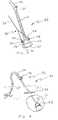
- FIG. 1is a perspective view of the vacuum device constructed in accordance with teachings of the invention and showing a suction cup with attached hose and or wand/handle.
- FIG. 2is a perspective view of an alternate embodiment of the invention wherein guide hooks may be utilized to facilitate placement of the device.
- FIG. 3is a perspective view of a third embodiment of the invention.
- FIG. 4is a perspective view of a fourth embodiment of the invention.
- FIG. 5is a perspective view of a traction arrangement including the device of FIG. 1 wherein the device is coupled to the operating room table to maintain the device in a desired position.
- FIG. 6is a traction arrangement including the device of FIG. 3 wherein the device is coupled to a self-retaining retractor.
- FIG. 7is a perspective view of the device of FIG. 2 in use during a laparoscopic procedure and wherein the device is tethered by a skin clip.
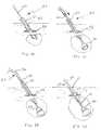
- FIGS. 8-13are perspective views of an alternate embodiment of the device of FIG. 1 for use in a laparoscopic procedure, and views of an exemplary procedure utilizing,the device.
- FIGS. 14A and 14Bare perspective views of the inventive device applied to laceration site to achieve tamponade.
- the device 20includes a suction cup 22 having a back wall 24 from which a side wall 26 depends, the side wall 26 forming a basal opening 28 at a side wall edge 30 for placement on an organ, or other tissue.
- the side wall edge 30may display a substantially rounded edge. It will be appreciated by those of skill in the art that this rounded edge may likewise facilitate sealing of the cup 22 against tissue, particularly in a mushroom-shaped cup 22 as illustrated in FIG. 1, inasmuch as the rounded edge may readily conform to certain irregularities in the tissue surface and maintain a sealing engagement as the tissue is drawn into the cup 22 .
- the cup 22may be of a range of sizes and of various compositions, depending upon the particular application in which it is utilized as described below.
- the cup 22will preferably run on the order of 3 to 205 mm (approximately 0.1 to 8 inches) in diameter, although it may be smaller or larger.
- the cup 22may be of any appropriate shape, so long as a seal may be established with the target tissue, and a vacuum established and maintained at a workable level.
- the cup 22 illustrated in FIG. 1has a generally mushroom shape, while the cup 22 illustrated in FIG. 2 has a generally bell shape.
- the cup 22may be formed of any appropriate material which is acceptable for surgical usage.
- the cup 22may be formed of rubber, plastic, silastic, silicone, plastic such as polyethylene, or metals, such as stainless steel to provide desired cup characteristics for a given usage, e.g., level of flexibility.
- the currently preferred designutilizes a polyethylene material which results in a relatively transparent cup 22 . In this way, the surgeon can readily visualize the interaction of the cup 22 with the tissue (see FIG. 2) and identify potential problems with the engagement or adverse reaction with the tissue.
- a vacuum opening 32is provided in one of the walls 24 , 26 of the cup 22 .
- a hose 34 connected to a standard vacuum source(not shown) is coupled to the opening 32 to direct the suction to the interior of the cup 22 .
- the hose 34is preferably composed of a flexible rubber or plastic, although it may be substantially rigid. While hose 34 may be coupled directly to the opening 32 during molding such that it forms a single piece, or ultrasonically welded or chemically bonded or the like, after molding.
- a hollow nipple 36is preferably provided around which the hose 34 may be appropriately secured. Barbs 38 may be provided about the nipple in order to enhance the strength of the coupling. Alternately, or in conjunction with the barbs 38 , the hose 34 may be chemically bonded, ultrasonically welded or the like to the cup 22 or nipple 36 .
- the device 20also includes tractioning structure 39 by which the cup 22 may be manipulated once placement and vacuum has been achieved.
- This structuremay be in the form of the hose 34 itself, which might function as a tether by which a tractive force may be applied. It will be appreciated that the tractioning structure 39 , such as the hose 34 , might additionally be of some assistance in manipulation and placement of the cup 22 .
- the nipple 36is elongated to form a hollow stem 40 , which acts as a control arm by which the cup 22 may be manipulated.
- a handle 42is coupled to the hollow stem 40 . It will be appreciated that the handle 42 may be separate from the vacuum hose 34 .
- manipulation of the cup 22may be provided by an external or removable structure.
- one or more elongated rods 44 having hooks 46 or the like on the distal endsmay be provided, as shown in FIG. 2 .
- the hooks 46may be engaged with openings 48 in the device 20 to maneuver the cup 22 into a desired position on a tissue. Once positioned, the hooks 46 may be removed or used to apply a tractive force to the cup 22 .
- the rods 44 and hooks 46will be particularly useful in placement and manipulation of cups which do not include a handle or elongated stem, such as the cups disclosed in FIGS. 2 and 3.
- a device 20 having the flexible hose 34 attached directly to the cup 22 , or to only a short nipple 36 , or a device 20 having no separate manipulation rod or handlemay include an elongated, stiffening rod or stylet 49 which stiffens a segment of the hose 34 and acts as a control arm to permit manipulation of the cup 22 .
- the stylet 49is preferably hollow, and is disposed within the hose 34 substantially adjacent the cup 22 such that the rod 49 functions in a manner similar to the elongated stem 40 of FIG. 1, while allowing the application of a vacuum.
- the stylet 49may further include a tether 50 or the like such that the rod 49 may be removed from the vacuum hose 34 by pulling the rod 49 axially therethrough.
- a rigid sheathmay be disposed around the hose 34 and slid in or out as needed.
- a tractioning structurewhich includes a traction cord 52 or the like may be provided. As illustrated in FIG. 1, the traction cord 52 may be coupled to the handle 42 by openings 48 through the handle 42 . Alternately, the traction cord may be coupled to the cup 22 by way of ears 54 extending from the nipple 36 , as shown in FIG. 2, or directly from the cup 22 as shown in FIG. 3 .
- the traction applied to the cup 22may be maintained mechanically, in lieu of an assistant or surgeon holding the traction by hand.
- the cord 52may be coupled to a frame 56 extending above the operating table 58 , as illustrated in FIG. 5 .
- the cord 52may be clamped to the frame 56 at a sliding bracket 60 , the frame 56 preferably comprising-upright supports 61 , which are bracketed to the table 58 at bracket 62 , and a crossbar 64 .
- the frame 56is preferably positioned at the head of the table 58 , as illustrated in FIG. 5, or at the foot of the table 58 such that it does not interfere with the surgeon's access to the surgical field 66 .
- the device 20may be coupled to a conventional self-retaining retractor 68 as illustrated in FIG. 6 . While it may be coupled by any appropriate method, the traction cord 52 may be hooked on a lock nut 70 of the retractor 68 . Similarly, during laparoscopic procedures, the cord 52 might be clipped via an appropriate clip 70 directly to the patient's skin, as illustrated in FIG. 7 . It will be appreciated that in this particular application, the cord 52 or other tether is applied through one incision, while the suction hose 34 extends through another incision.
- the suction levelmay be maintained within an acceptable range without continuous adjustment of the pumping device.
- a valve or clamp 72 of any known designmay be provided between the cup 22 and the pump (not shown). As shown in FIG. 4, the clamp 72 may be disposed such that it simply crimps the flexible vacuum hose 34 . In this way, the established vacuum will be essentially maintained on the tissue.
- the vacuum device 20may be utilized in procedures which are intra- or extra-cavitary, that is, procedures which involve body surfaces, orifices, or internal organs, and in both laparotomy and laparoscopic procedures.
- the device 20can be utilized as a retractor by attaching to a target organ to allow for better visualization of other organs, as a manipulator to move target organs from one position to another, or as an extractor to “deliver” organs from inside to outside of the body.
- the level of suction applied to the cupwill be dependent not only upon the features of the device 20 including the size of the cup 22 , but also on the features of the particular target organ and the type of movement which is required. It will be appreciated that the level of traction force applied will typically be lower than that used when delivering newborns, and, accordingly, vacuum required to prevent release of the cup from the target organ will generally be less than the vacuum level applied with an obstetrical vacuum extractor during delivery.
- a vacuumWhen a vacuum is applied to a suction cup 22 on a structure having a blood flow, blood will typically pool inside the site, which may lead to the formation of a hematoma.
- an obstetrical vacuum extractorWhen an obstetrical vacuum extractor is applied to a fetal scalp during vacuum extraction assisted deliveries of newborns, for example, occasionally a small bruise or hematoma occurs on the scalp (cephalohematoma). Additionally, some soft tissue edema and swelling may occur on the area of the scalp where the vacuum was applied.
- tissue to which the invention is appliedThis is called a “chinion” or “caput.”
- a hematomamay be possible for tissues such as uterine muscle, while it would not be likely in pathologic or physiologic cystic entities, such as ovarian cysts. It will be appreciated, however, that these effects are less likely to result in target tissue during use of the present invention because the level of vacuum applied to such tissue to maintain a traction force is generally considerably less than that required during Vacuum assisted delivery.
- the device 20is particularly useful during laparoscopic procedures.
- the cup 22is preferably formed of a relatively flexible, but resilient material such that the cup 22 may be advanced through a sheath, cannula, trocar, or other endoscopic device into the body cavity.
- an incision 82 amay be made, a trocar (not shown) and sleeve, cannula, or sheath 80 inserted into the incision 82 a , and the trocar removed.
- the flexible cup 22 for use in laparoscopic proceduresis preferably formed of a natural rubber or polymer material such as, for example, silastic, flexible rubber, or a thermoplastic elastomer such as Kraton.
- a flexible cup 22 constructed in accordance with teachings of this inventionis schematically illustrated folded within a cannula or sheath 80 for delivery through a body cavity through the sheath 80 inserted into the small incision 82 a . Once the suction cup 22 is intra-cavitarily positioned, the sheath 80 may be withdrawn slightly from the cup 22 as illustrated in FIGS. 9 and 11.
- the elongated hollow stem 40may be used to advance the cup 22 and to position the cup 22 .
- a vacuummay then be applied via the vacuum hose 34 , and an appropriate traction applied to the stem 40 or hose 34 to pull the tissue toward the incision 82 site.
- the hose 34must be securely coupled to the cup 22 and preferably be made of strong flexible rubber or plastic. Using this arrangement, much thought must be given to the location of the incision 82 to provide optimal traction in a desired direction to facilitate surgery.
- a clamp device used on the exterior portion of the hose 34can both serve to block egress of the vacuum and anchor the hose 34 firmly to the body wall above the incision 82 , as shown, for example, in FIG. 13 .
- the clamp deviceaffixes the hose 34 in the stretched or tension position to the abdominal wall to maintain the retraction.
- a plastic or metal clamp or the likemay be used to affix the device 20 to another part of the patient or other structure, such as the table, as illustrated in FIG. 5, for example.
- the cup 22may be applied to the target tissue and maneuvered according to any of the arrangements disclosed herein.
- the cup 22 in FIG. 7the cup of FIG. 3 is inserted through a trocar 81 extending through a first incision 82 a and by means of the stylet 48 . If the stylet 48 is then withdrawn to just below the incision line, the hose 34 becomes flexible.
- the tether 52 or rods 44 with hooksmay likewise be delivered through the original trocar or sheath or they may be extended through a second incision 82 b , as illustrated in FIG. 2, and utilized to manipulate the cup 22 or apply a tensioning force. In this way, the cup 22 may be tensioned or manipulated at an angle other than would generally be attainable when manipulating the device 20 through a single incision.
- the cupwill be applied to the ovary adjacent or over the cyst area.
- An incisionis then made with a second device through a second sheath to expose the cyst and the surrounding ovarian tissue.
- the cupis then reapplied directly to the cyst wall. Traction is asserted on the cup and cyst, and counter-dissection performed to free the cyst from the surrounding ovary. Suction is maintained and the cyst is pulled through the original incision or through a second abdominal or transvaginal incision intact. It will be appreciated that the original incision may need slight widening if it is utilized. Similar procedures may be utilized for excising or manipulating tumors in neurosurgical or urological surgeries.
- the suctionmay be released by, for example, opening the valve or clamp.
- the flaccid suction cup 22may then be reintroduced to the sheath 80 , and the sheath removed along with the suction cup 22 from the body by asserting traction on the hose 34 , stem 40 , or other structure.
- the vacuum device 20may be utilized in a variety of procedures. For example, occasionally internal organs can become adherent to the abdomen or pelvic sidewalls or to other structures rendering them fixed and immovable.
- a suction cup appropriately sized for the target organmay be disposed, suction applied, and traction or countertraction applied gently to retract the organ or to lift it out of the body cavity so that adhesions may be lysed by the surgeon or assistant surgeon. Should other tissue obscure visualization of the target organ or adhesions, additional suction devices may be applied.
- the suction device 20is particularly effective in surgery or gynecological surgery involving the extraction or removal of tumors from within organ structures.
- fibroid tumorssmooth muscle tumors of varying shapes and sizes with rounded smooth surfaces
- a surgeon's assistanttypically uses sharp extraction instruments, such as clamps or hooks, to put traction on the tumor while the surgeon bluntly and sharply dissects the tumor free from the organ.
- the suction device 20can be applied to the tumor and traction applied as the surgeon dissects the tumor from the organ.
- the surgeoncan avoid the additional blood loss that accompanies the use of sharp tools to extract the tumor, as such sharp tools often cause maceration and laceration of the tissues during traction.
- the optimal diameter of the cup 22may vary as it is chosen to correlate with the diameter of the structure to be removed or extracted, it has been determined that a vacuum device 20 including a cup 22 having a diameter on the order of 20 mm up to 80-100 mm and formed of a plastic, metal, silastic, or rubber material is particularly useful in this type of surgery.
- the suction cup 22can be applied to the ovary, a vacuum applied, and the adhesions or attachment between the tube and ovary can be better visualized and any attachments more safely lysed. This avoids any sharp instrument being used to manipulate either the tube or ovary, avoiding complications which may lead to bleeding, infection, or unnecessary removal of adjacent normal organs. It has been determined that a vacuum device 20 including a cup 22 having a diameter on the order of 10-50 mm and formed of a flexible plastic, silastic or rubber material is particularly useful in this type of surgery.
- formed cups of the following diametersare likewise desirable for the following types of tissues during various procedures: gallbladder, 20-50 mm; uterus 40-100 mm; fibroid 10-100 mm; large ectopic pregnancy, 20-50 mm; cecum (transfixion through laparoscope as assistance in appendectomy), 20-50 mm; tumors, 20-100 mm.
- the vacuum device 20may be utilized as a tamponade for bleeding tissue.
- the cup 22 and the vacuummay be applied at that site until the surgery can progress sufficiently to repair or remove the structure in question.
- a suction cup 22can be applied adjacent or over the bleeding site, and negative pressure applied to curtail bloodflow in and around the bleeding site until the organ or pathologic entity can be safely treated or excised.
- FIG. 14Aschematically illustrates an organ 90 having a ruptured cyst or other laceration 92 . Under these circumstances, a cup 22 may be positioned over the laceration site 92 and sufficient vacuum applied to squeeze the tissue surrounding the site and transmit pressure on the periphery of the site, closing the aperture of the laceration to either slow or completely stop the bleeding.
- the procedureis likewise applicable to the exterior surface of the body such that the vacuum device 20 acts as vacuum tourniquet of sorts.
- the cup 22is applied to a wound and the applied vacuum transmits the tissue deep in the wound site to create a tamponade or pressure effect, much like applying pressure to a bleeding wound.
- the procedureis particularly useful on the torso of the body, where a tourniquet could not be applied.
- the proceduremay readily be applied in trauma situations where facilities are unavailable for full treatment of the wound.
- transfusioncan introduce pathogens such as the AIDS and hepatitis virus to the recipient, any strategy which can efficiently curtail or arrest blood loss as a temporizing method during surgery should be welcomed by the surgical community.
Landscapes
- Health & Medical Sciences (AREA)
- Life Sciences & Earth Sciences (AREA)
- Surgery (AREA)
- Heart & Thoracic Surgery (AREA)
- Veterinary Medicine (AREA)
- Biomedical Technology (AREA)
- Engineering & Computer Science (AREA)
- Animal Behavior & Ethology (AREA)
- General Health & Medical Sciences (AREA)
- Public Health (AREA)
- Medical Informatics (AREA)
- Molecular Biology (AREA)
- Nuclear Medicine, Radiotherapy & Molecular Imaging (AREA)
- Vascular Medicine (AREA)
- Anesthesiology (AREA)
- Hematology (AREA)
- Surgical Instruments (AREA)
Abstract
Description
Claims (5)
Priority Applications (7)
| Application Number | Priority Date | Filing Date | Title |
|---|---|---|---|
| US09/489,632US6641575B1 (en) | 1999-01-26 | 2000-01-24 | Surgical vacuum instrument for retracting, extracting, and manipulating tissue |
| US10/677,848US7935094B2 (en) | 1999-01-26 | 2003-10-02 | Vacuum instrument for slowing or arresting the flow of blood |
| US11/067,512US20050203334A1 (en) | 1999-01-26 | 2005-02-25 | Vacuum instrument for laparotomy procedures |
| US13/073,723US8608714B2 (en) | 1999-01-26 | 2011-03-28 | Vacuum instrument for slowing or arresting the flow of blood |
| US13/450,464US8915894B1 (en) | 2000-01-24 | 2012-04-18 | Vacuum cup for delivery of agents during vacuum treatment |
| US13/751,343US9138216B2 (en) | 2000-01-24 | 2013-01-28 | Portable regulated vacuum pump for medical procedures |
| US14/107,511US20140121464A1 (en) | 1999-01-26 | 2013-12-16 | Vacuum instrument for slowing or arresting the flow of blood |
Applications Claiming Priority (2)
| Application Number | Priority Date | Filing Date | Title |
|---|---|---|---|
| US11730099P | 1999-01-26 | 1999-01-26 | |
| US09/489,632US6641575B1 (en) | 1999-01-26 | 2000-01-24 | Surgical vacuum instrument for retracting, extracting, and manipulating tissue |
Related Child Applications (1)
| Application Number | Title | Priority Date | Filing Date |
|---|---|---|---|
| US10/677,848ContinuationUS7935094B2 (en) | 1999-01-26 | 2003-10-02 | Vacuum instrument for slowing or arresting the flow of blood |
Publications (1)
| Publication Number | Publication Date |
|---|---|
| US6641575B1true US6641575B1 (en) | 2003-11-04 |
Family
ID=29272594
Family Applications (4)
| Application Number | Title | Priority Date | Filing Date |
|---|---|---|---|
| US09/489,632Expired - LifetimeUS6641575B1 (en) | 1999-01-26 | 2000-01-24 | Surgical vacuum instrument for retracting, extracting, and manipulating tissue |
| US10/677,848Expired - LifetimeUS7935094B2 (en) | 1999-01-26 | 2003-10-02 | Vacuum instrument for slowing or arresting the flow of blood |
| US13/073,723Expired - LifetimeUS8608714B2 (en) | 1999-01-26 | 2011-03-28 | Vacuum instrument for slowing or arresting the flow of blood |
| US14/107,511AbandonedUS20140121464A1 (en) | 1999-01-26 | 2013-12-16 | Vacuum instrument for slowing or arresting the flow of blood |
Family Applications After (3)
| Application Number | Title | Priority Date | Filing Date |
|---|---|---|---|
| US10/677,848Expired - LifetimeUS7935094B2 (en) | 1999-01-26 | 2003-10-02 | Vacuum instrument for slowing or arresting the flow of blood |
| US13/073,723Expired - LifetimeUS8608714B2 (en) | 1999-01-26 | 2011-03-28 | Vacuum instrument for slowing or arresting the flow of blood |
| US14/107,511AbandonedUS20140121464A1 (en) | 1999-01-26 | 2013-12-16 | Vacuum instrument for slowing or arresting the flow of blood |
Country Status (1)
| Country | Link |
|---|---|
| US (4) | US6641575B1 (en) |
Cited By (47)
| Publication number | Priority date | Publication date | Assignee | Title |
|---|---|---|---|---|
| US20050251183A1 (en)* | 2002-09-13 | 2005-11-10 | Damage Control Surgical Technologies, Inc. | Method and apparatus for vascular and visceral clipping |
| US6979324B2 (en) | 2002-09-13 | 2005-12-27 | Neogen Technologies, Inc. | Closed wound drainage system |
| US20060040817A1 (en)* | 1995-06-26 | 2006-02-23 | Ratzel Richard O | Cushioning conversion machine and method |
| US20060149135A1 (en)* | 2003-07-02 | 2006-07-06 | Adrian Paz | Virtual ports devices and method |
| US7179224B2 (en)* | 2003-12-30 | 2007-02-20 | Cardiothoracic Systems, Inc. | Organ manipulator and positioner and methods of using the same |
| US20070078441A1 (en)* | 2005-09-14 | 2007-04-05 | Adams Mark L | Medical catheter external bolster having strain relief member |
| US20070119461A1 (en)* | 2005-11-18 | 2007-05-31 | Brian Biancucci | Article isolation device and methods |
| US20080033343A1 (en)* | 2004-01-20 | 2008-02-07 | Kathrani Biten K | Method for accessing an operative space |
| US7520872B2 (en) | 2002-09-13 | 2009-04-21 | Neogen Technologies, Inc. | Closed wound drainage system |
| US20090248065A1 (en)* | 2008-03-26 | 2009-10-01 | Miwatec Co., Ltd. | Hemostatic device sealing damaged site with vacuum |
| US20090270789A1 (en)* | 2006-04-14 | 2009-10-29 | Maxymiv George W | Suction dome for atraumatically grasping or manipulating tissue |
| US7651484B2 (en) | 2006-02-06 | 2010-01-26 | Kci Licensing, Inc. | Systems and methods for improved connection to wound dressings in conjunction with reduced pressure wound treatment systems |
| US20100256662A1 (en)* | 2008-10-23 | 2010-10-07 | Racenet Danyel J | Vacuum assisted surgical dissection tools |
| US7824384B2 (en) | 2004-08-10 | 2010-11-02 | Kci Licensing, Inc. | Chest tube drainage system |
| US20100298866A1 (en)* | 2009-05-19 | 2010-11-25 | Tyco Healthcare Group Lp | Wound closure system and method of use |
| US20100317926A1 (en)* | 2009-06-15 | 2010-12-16 | Ashutosh Kaul | Suction-Based Tissue Manipulator |
| US8029498B2 (en) | 2006-03-14 | 2011-10-04 | Kci Licensing Inc. | System for percutaneously administering reduced pressure treatment using balloon dissection |
| US8057449B2 (en) | 2007-02-09 | 2011-11-15 | Kci Licensing Inc. | Apparatus and method for administering reduced pressure treatment to a tissue site |
| US8083712B2 (en) | 2007-03-20 | 2011-12-27 | Neogen Technologies, Inc. | Flat-hose assembly for wound drainage system |
| US20120046604A1 (en)* | 2010-08-22 | 2012-02-23 | Oz Cabiri | Tissue suction device |
| US8235939B2 (en) | 2006-02-06 | 2012-08-07 | Kci Licensing, Inc. | System and method for purging a reduced pressure apparatus during the administration of reduced pressure treatment |
| US8267908B2 (en) | 2007-02-09 | 2012-09-18 | Kci Licensing, Inc. | Delivery tube, system, and method for storing liquid from a tissue site |
| US8439893B2 (en)* | 2002-06-11 | 2013-05-14 | Medela Holding Ag | System and method for efficient drainage of body cavity |
| US8529526B2 (en) | 2009-10-20 | 2013-09-10 | Kci Licensing, Inc. | Dressing reduced-pressure indicators, systems, and methods |
| US20130274717A1 (en)* | 2011-04-15 | 2013-10-17 | Raymond Dunn | Surgical cavity drainage and closure system |
| US20140074110A1 (en)* | 2012-03-15 | 2014-03-13 | Inpress Technologies | Uterine hemorrhage controlling system and method |
| US8939933B2 (en) | 2006-03-14 | 2015-01-27 | Kci Licensing, Inc. | Manifolds, systems, and methods for administering reduced pressure to a subcutaneous tissue site |
| WO2015104089A1 (en)* | 2014-01-10 | 2015-07-16 | Spielmann Alain | Surgical kit and associated production method |
| US20150335323A1 (en)* | 2012-12-20 | 2015-11-26 | Aesculap Ag | Surgical positioning instrument for supporting and holding organs |
| US9456860B2 (en) | 2006-03-14 | 2016-10-04 | Kci Licensing, Inc. | Bioresorbable foaming tissue dressing |
| US9550014B2 (en) | 2012-03-15 | 2017-01-24 | Inpress Technologies, Inc. | Postpartum uterine contractile apparatus and method |
| CN106491190A (en)* | 2016-12-04 | 2017-03-15 | 李长慧 | The convenient ovarian tumor perforator for adjusting angle |
| US20170165116A1 (en)* | 2015-12-15 | 2017-06-15 | University Of Massachusetts | Negative pressure wound closure devices and methods |
| US10028731B2 (en) | 2013-11-12 | 2018-07-24 | Genzyme Corporation | Barrier application device |
| CN111134742A (en)* | 2020-03-18 | 2020-05-12 | 卢乐 | Tumor picker for oncology department |
| US10814049B2 (en) | 2015-12-15 | 2020-10-27 | University Of Massachusetts | Negative pressure wound closure devices and methods |
| US20200352602A1 (en)* | 2012-03-15 | 2020-11-12 | Alydia Health, Inc. | Uterine hemorrhage controlling system and method |
| US11083631B2 (en) | 2012-07-16 | 2021-08-10 | University Of Massachusetts | Negative pressure wound closure device |
| US11166726B2 (en) | 2011-02-04 | 2021-11-09 | University Of Massachusetts | Negative pressure wound closure device |
| US11241337B2 (en) | 2012-05-24 | 2022-02-08 | Smith & Nephew, Inc. | Devices and methods for treating and closing wounds with negative pressure |
| US11419767B2 (en) | 2013-03-13 | 2022-08-23 | University Of Massachusetts | Negative pressure wound closure device and systems and methods of use in treating wounds with negative pressure |
| US11439539B2 (en) | 2015-04-29 | 2022-09-13 | University Of Massachusetts | Negative pressure wound closure device |
| US11471586B2 (en) | 2015-12-15 | 2022-10-18 | University Of Massachusetts | Negative pressure wound closure devices and methods |
| US11517336B2 (en) | 2016-08-24 | 2022-12-06 | Alydia Health, Inc. | Uterine hemorrhage controlling system and method |
| US20230210561A1 (en)* | 2022-01-01 | 2023-07-06 | Xiamen Brana Design Co., Ltd. | Fetal Intrauterine Positioning Fixation Device and System Thereof |
| CN118044845A (en)* | 2024-04-16 | 2024-05-17 | 四川省肿瘤医院 | Tumor taking-out device |
| US12133790B2 (en) | 2013-10-21 | 2024-11-05 | Smith & Nephew, Inc. | Negative pressure wound closure device |
Families Citing this family (14)
| Publication number | Priority date | Publication date | Assignee | Title |
|---|---|---|---|---|
| CA2656388C (en)* | 2006-07-05 | 2011-03-29 | Wilson-Cook Medical Inc. | Suction clip |
| EP2182853A4 (en)* | 2007-08-10 | 2012-08-08 | Univ Yale | SUSPENSION / RETRACTION DEVICE FOR SURGICAL HANDLING |
| FR2927249B1 (en)* | 2008-02-08 | 2011-03-04 | Univ Joseph Fourier | DEVICE FOR HEMOSTATIC CONTROL OF BLOOD FLOW |
| JP2009273559A (en)* | 2008-05-13 | 2009-11-26 | Tokyo Iken Kk | Hemostatic device |
| JP4772853B2 (en)* | 2008-11-27 | 2011-09-14 | 賢治 石井 | Suction cup for delivery |
| US9421316B2 (en)* | 2010-05-04 | 2016-08-23 | Stephen A. Leeflang | Apparatus and methods for accessing the lymphatic system |
| CA2811828A1 (en)* | 2010-09-20 | 2012-03-29 | Britamed Incorporated | Vacuum anchoring catheter |
| KR101082762B1 (en)* | 2011-02-18 | 2011-11-10 | 이정삼 | Laparoscopic Traction System |
| US9962175B2 (en)* | 2013-10-16 | 2018-05-08 | Gary Lovell | Methods of use of an anatomic structure extractor |
| US20180339090A1 (en)* | 2017-05-25 | 2018-11-29 | Michael Joseph Santana | Therapeutic suction cup |
| AU201716242S (en)* | 2017-10-13 | 2017-11-23 | JCT Solutions Pty Ltd | Obstetrical vacuum apparatus |
| AU201716243S (en)* | 2017-10-13 | 2017-11-23 | JCT Solutions Pty Ltd | Obstetrical vacuum apparatus |
| AU201716244S (en)* | 2017-10-13 | 2017-11-23 | JCT Solutions Pty Ltd | Obstetrical vacuum apparatus |
| EP4076214B1 (en)* | 2019-12-16 | 2025-01-15 | Solike Trading GmbH | Tissue holding device |
Citations (34)
| Publication number | Priority date | Publication date | Assignee | Title |
|---|---|---|---|---|
| US1294284A (en) | 1918-11-14 | 1919-02-11 | Charles Frederick Logeman | Tweezers for surgical operations. |
| US2082782A (en) | 1935-10-03 | 1937-06-08 | Alfred G Allen | Vacuum tenaculum |
| US3765408A (en)* | 1972-03-16 | 1973-10-16 | Kawai Tosando Kk | Soft obstetric vacuum cup for assisting childbirth |
| US3768477A (en) | 1972-06-05 | 1973-10-30 | R Anders | Tongue depressing aspirating tip |
| US4049000A (en) | 1975-08-01 | 1977-09-20 | Williams Robert W | Suction retraction instrument |
| US4314560A (en) | 1979-11-28 | 1982-02-09 | Helfgott Maxwell A | Powered handpiece for endophthalmic surgery |
| US4957484A (en)* | 1988-07-26 | 1990-09-18 | Automedix Sciences, Inc. | Lymph access catheters and methods of administration |
| US4986839A (en) | 1988-11-10 | 1991-01-22 | Surgical Laser Products, Inc. | Self-contained air enhancement and laser plume evacuation system |
| US5019086A (en) | 1989-09-12 | 1991-05-28 | Neward Theodore C | Manipulable vacuum extractor for childbirth and method of using the same |
| US5124364A (en) | 1990-12-05 | 1992-06-23 | Basf Aktiengesellschaft | Composite foams of low thermal conductivity |
| US5123403A (en) | 1991-07-10 | 1992-06-23 | Lavyne Michael H | Suction nerve root retractor |
| US5196003A (en)* | 1990-11-06 | 1993-03-23 | Ethicon, Inc. | Endoscopic surgical instrument for taking hold of tissue |
| US5224947A (en)* | 1991-10-21 | 1993-07-06 | Cooper Richard N | Soft, readily expandable vacuum bell assembly |
| US5250075A (en) | 1992-09-02 | 1993-10-05 | Behnam Badie | Bayonet sucker forceps |
| US5259836A (en) | 1987-11-30 | 1993-11-09 | Cook Group, Incorporated | Hysterography device and method |
| US5281229A (en)* | 1991-08-09 | 1994-01-25 | Neward Theodore C | Obstetrical vacuum extractor |
| US5395379A (en) | 1993-07-22 | 1995-03-07 | Deutchman; Mark E. | Extractor for childbirth and aspirator/injector device |
| US5423830A (en)* | 1993-07-07 | 1995-06-13 | Schneebaum; Cary W. | Polyp retrieval method and associated instrument assembly |
| US5472438A (en) | 1993-07-22 | 1995-12-05 | Case Western Reserve University | Laproscopic vacuum delivery apparatus for a diaphragm daper |
| US5472426A (en) | 1991-09-12 | 1995-12-05 | B.E.I. Medical | Cervical discectomy instruments |
| US5507752A (en) | 1990-09-06 | 1996-04-16 | Board Of Regents, The University Of Texas System | Obstetric bonnet for assisting childbirth and method of manufacturing the same |
| US5693058A (en)* | 1995-06-09 | 1997-12-02 | Cavanagh; Alexander J. M. | Obstetric vacuum extractor |
| US5727569A (en) | 1996-02-20 | 1998-03-17 | Cardiothoracic Systems, Inc. | Surgical devices for imposing a negative pressure to fix the position of cardiac tissue during surgery |
| US5762606A (en) | 1997-05-16 | 1998-06-09 | Minnich; Thomas E. | Combined eyelid retractor and eye flushing device |
| US5769784A (en) | 1995-11-27 | 1998-06-23 | Hill-Rom, Inc. | Skin perfusion evaluation apparatus and method |
| US5799661A (en)* | 1993-02-22 | 1998-09-01 | Heartport, Inc. | Devices and methods for port-access multivessel coronary artery bypass surgery |
| US5836311A (en) | 1995-09-20 | 1998-11-17 | Medtronic, Inc. | Method and apparatus for temporarily immobilizing a local area of tissue |
| US5865827A (en) | 1997-06-03 | 1999-02-02 | Bullister; Edward T | Vacuum device for securing human tissue |
| US5865730A (en) | 1997-10-07 | 1999-02-02 | Ethicon Endo-Surgery, Inc. | Tissue stabilization device for use during surgery having remotely actuated feet |
| US5885271A (en) | 1997-03-14 | 1999-03-23 | Millennium Cardiac Strategies, Inc. | Device for regional immobilization of a compliant body |
| US5891017A (en) | 1997-01-31 | 1999-04-06 | Baxter Research Medical, Inc. | Surgical stabilizer and method for isolating and immobilizing cardiac tissue |
| US5935136A (en)* | 1997-05-09 | 1999-08-10 | Pristech, Inc. | Obstetrical vacuum extractor cup with soft molded lip |
| US6074399A (en)* | 1998-05-08 | 2000-06-13 | Clinical Innovations | Hand-held fetal vacuum extractor having an integrated pump and handle |
| US6506166B1 (en) | 1998-08-27 | 2003-01-14 | Shoshan Hendler | Apparatus and method for acquisition and retrieval of resected biological specimens |
Family Cites Families (10)
| Publication number | Priority date | Publication date | Assignee | Title |
|---|---|---|---|---|
| US1460927A (en)* | 1922-03-28 | 1923-07-03 | Ralph S Thompson | Vacuum cup |
| US5186711A (en) | 1989-03-07 | 1993-02-16 | Albert Einstein College Of Medicine Of Yeshiva University | Hemostasis apparatus and method |
| US5149331A (en) | 1991-05-03 | 1992-09-22 | Ariel Ferdman | Method and device for wound closure |
| US5474056A (en)* | 1991-09-18 | 1995-12-12 | Laborie Enterprises Inc. | Suspension and retraction system for endoscopic surgery and method for using same |
| US5636643A (en)* | 1991-11-14 | 1997-06-10 | Wake Forest University | Wound treatment employing reduced pressure |
| US5645081A (en) | 1991-11-14 | 1997-07-08 | Wake Forest University | Method of treating tissue damage and apparatus for same |
| US5415666A (en)* | 1992-03-23 | 1995-05-16 | Advanced Surgical, Inc. | Tethered clamp retractor |
| US5742438A (en)* | 1994-09-16 | 1998-04-21 | In Focus Systems, Inc. | Projection illumination system |
| US5643183A (en)* | 1995-06-29 | 1997-07-01 | Hill; Joseph C. | Waterproof cover for casts and bandages |
| US5810840A (en) | 1997-01-14 | 1998-09-22 | Lindsay; Richard G. | Vacuum extractor |
- 2000
- 2000-01-24USUS09/489,632patent/US6641575B1/ennot_activeExpired - Lifetime
- 2003
- 2003-10-02USUS10/677,848patent/US7935094B2/ennot_activeExpired - Lifetime
- 2011
- 2011-03-28USUS13/073,723patent/US8608714B2/ennot_activeExpired - Lifetime
- 2013
- 2013-12-16USUS14/107,511patent/US20140121464A1/ennot_activeAbandoned
Patent Citations (34)
| Publication number | Priority date | Publication date | Assignee | Title |
|---|---|---|---|---|
| US1294284A (en) | 1918-11-14 | 1919-02-11 | Charles Frederick Logeman | Tweezers for surgical operations. |
| US2082782A (en) | 1935-10-03 | 1937-06-08 | Alfred G Allen | Vacuum tenaculum |
| US3765408A (en)* | 1972-03-16 | 1973-10-16 | Kawai Tosando Kk | Soft obstetric vacuum cup for assisting childbirth |
| US3768477A (en) | 1972-06-05 | 1973-10-30 | R Anders | Tongue depressing aspirating tip |
| US4049000A (en) | 1975-08-01 | 1977-09-20 | Williams Robert W | Suction retraction instrument |
| US4314560A (en) | 1979-11-28 | 1982-02-09 | Helfgott Maxwell A | Powered handpiece for endophthalmic surgery |
| US5259836A (en) | 1987-11-30 | 1993-11-09 | Cook Group, Incorporated | Hysterography device and method |
| US4957484A (en)* | 1988-07-26 | 1990-09-18 | Automedix Sciences, Inc. | Lymph access catheters and methods of administration |
| US4986839A (en) | 1988-11-10 | 1991-01-22 | Surgical Laser Products, Inc. | Self-contained air enhancement and laser plume evacuation system |
| US5019086A (en) | 1989-09-12 | 1991-05-28 | Neward Theodore C | Manipulable vacuum extractor for childbirth and method of using the same |
| US5507752A (en) | 1990-09-06 | 1996-04-16 | Board Of Regents, The University Of Texas System | Obstetric bonnet for assisting childbirth and method of manufacturing the same |
| US5196003A (en)* | 1990-11-06 | 1993-03-23 | Ethicon, Inc. | Endoscopic surgical instrument for taking hold of tissue |
| US5124364A (en) | 1990-12-05 | 1992-06-23 | Basf Aktiengesellschaft | Composite foams of low thermal conductivity |
| US5123403A (en) | 1991-07-10 | 1992-06-23 | Lavyne Michael H | Suction nerve root retractor |
| US5281229A (en)* | 1991-08-09 | 1994-01-25 | Neward Theodore C | Obstetrical vacuum extractor |
| US5472426A (en) | 1991-09-12 | 1995-12-05 | B.E.I. Medical | Cervical discectomy instruments |
| US5224947A (en)* | 1991-10-21 | 1993-07-06 | Cooper Richard N | Soft, readily expandable vacuum bell assembly |
| US5250075A (en) | 1992-09-02 | 1993-10-05 | Behnam Badie | Bayonet sucker forceps |
| US5799661A (en)* | 1993-02-22 | 1998-09-01 | Heartport, Inc. | Devices and methods for port-access multivessel coronary artery bypass surgery |
| US5423830A (en)* | 1993-07-07 | 1995-06-13 | Schneebaum; Cary W. | Polyp retrieval method and associated instrument assembly |
| US5395379A (en) | 1993-07-22 | 1995-03-07 | Deutchman; Mark E. | Extractor for childbirth and aspirator/injector device |
| US5472438A (en) | 1993-07-22 | 1995-12-05 | Case Western Reserve University | Laproscopic vacuum delivery apparatus for a diaphragm daper |
| US5693058A (en)* | 1995-06-09 | 1997-12-02 | Cavanagh; Alexander J. M. | Obstetric vacuum extractor |
| US5836311A (en) | 1995-09-20 | 1998-11-17 | Medtronic, Inc. | Method and apparatus for temporarily immobilizing a local area of tissue |
| US5769784A (en) | 1995-11-27 | 1998-06-23 | Hill-Rom, Inc. | Skin perfusion evaluation apparatus and method |
| US5727569A (en) | 1996-02-20 | 1998-03-17 | Cardiothoracic Systems, Inc. | Surgical devices for imposing a negative pressure to fix the position of cardiac tissue during surgery |
| US5891017A (en) | 1997-01-31 | 1999-04-06 | Baxter Research Medical, Inc. | Surgical stabilizer and method for isolating and immobilizing cardiac tissue |
| US5885271A (en) | 1997-03-14 | 1999-03-23 | Millennium Cardiac Strategies, Inc. | Device for regional immobilization of a compliant body |
| US5935136A (en)* | 1997-05-09 | 1999-08-10 | Pristech, Inc. | Obstetrical vacuum extractor cup with soft molded lip |
| US5762606A (en) | 1997-05-16 | 1998-06-09 | Minnich; Thomas E. | Combined eyelid retractor and eye flushing device |
| US5865827A (en) | 1997-06-03 | 1999-02-02 | Bullister; Edward T | Vacuum device for securing human tissue |
| US5865730A (en) | 1997-10-07 | 1999-02-02 | Ethicon Endo-Surgery, Inc. | Tissue stabilization device for use during surgery having remotely actuated feet |
| US6074399A (en)* | 1998-05-08 | 2000-06-13 | Clinical Innovations | Hand-held fetal vacuum extractor having an integrated pump and handle |
| US6506166B1 (en) | 1998-08-27 | 2003-01-14 | Shoshan Hendler | Apparatus and method for acquisition and retrieval of resected biological specimens |
Non-Patent Citations (16)
| Title |
|---|
| Argenta, L. C. and Morykwas, M. J. (1997) Vacuum-Assisted Closure: A New Method for Wound Control and Treatment: Clinical Experience. Ann. Plast. Surg. 38:563-577. |
| Bale, R. J., et al. (1997) Minimally Invasive Head Holder to Improve the Performance of Frameless Stereotactic Surgery. Laryngoscope 107:373-377. |
| Brock, W. B., et al. (1995) Temporary Closure of Open Abdominal Wounds: The Vacuum Pack. American Surgeon 61:30-35. |
| Chamberlain, G. and Steer, P. (1999) ABC of labour care: Operative delivery. BMJ 318:1260-1264. |
| Chua Patel, C. T., et al. (2000) Vacuum-Assisted Wound Closure. AJN 100(12):45-48. |
| Jukema, G. N., et al. (1997) Vacuum Sealing of Osteomyelitis and Infections of the Soft Tissue. Langenbecks Arch. Chir. Suppl. II (Kongressbericht 1997) 114:581-585. |
| Kim, E. D. and Lipschultz, L. I. (1997) Advances in the Treatment of Organic Erectile Dysfunction. Hosp. Pract. 32:101-120. |
| Klemm, B. and Salm, R. (1995) Vacuum-Supported Endoscopic Access. End. Surg 3:58-62. |
| Morykwas, M. J., et al. (1997) Vacuum-Assisted Closure: A New Method for Wound Control and Treatment: Animal Studies and Basic Foundation. Ann. Plast. Surg. 38:553-562. |
| Muller, G. (1997) Vacuum-Sealing Technique in Septic Surgery. Langenbecks Arch. Chir. Suppl. Kongressbd 114:537-541. |
| Mullner, T., et al. (1997) The use of negative pressure to promote the healing of tissue defects: a clinical trial using the vacuum sealing technique. Br. J. Plastic Surg. 50:194-199. |
| Pelosi, M.A. et al. (1984) "Use of the soft silicone obstetric vacuum cup to facilitate delivery and manipulation of large pelvic masses at operation"; American Journal of Obstetrics and Gynecology; v. 148, pp. 337-339. |
| Sames, C. P., et al. (1977) Sealing of wounds with vacuum drainage. Br. Med. J. 2:1223. |
| Smith, L. A., et al. (1997) Vacuum Pack Technique of Temporary Abdominal Closure: A Four-Year Experience. Am. Surg. 63(12):1102-1108. |
| Soderdahl, D. W., et al. (1997) The Use of an External Vacuum Device to Augment a Penile Prosthesis. Tech. Urol. 3(2):100-102. |
| Won, B. et al. (1999) "Stereotactic Biopsy of Ductal Carcinoma In Situ of the Breast Using an I I-Gauge Vacuum-Assisted Device: Persistent Underestimation of Disease"; American Journal of Roentgenology, v.173, pp. 227-229. |
Cited By (80)
| Publication number | Priority date | Publication date | Assignee | Title |
|---|---|---|---|---|
| US20060247116A9 (en)* | 1995-06-26 | 2006-11-02 | Ratzel Richard O | Cushioning conversion machine and method |
| US20060040817A1 (en)* | 1995-06-26 | 2006-02-23 | Ratzel Richard O | Cushioning conversion machine and method |
| US8439893B2 (en)* | 2002-06-11 | 2013-05-14 | Medela Holding Ag | System and method for efficient drainage of body cavity |
| US7322995B2 (en)* | 2002-09-13 | 2008-01-29 | Damage Control Surgical Technologies, Inc. | Method and apparatus for vascular and visceral clipping |
| US7520872B2 (en) | 2002-09-13 | 2009-04-21 | Neogen Technologies, Inc. | Closed wound drainage system |
| US20050251183A1 (en)* | 2002-09-13 | 2005-11-10 | Damage Control Surgical Technologies, Inc. | Method and apparatus for vascular and visceral clipping |
| US7731702B2 (en) | 2002-09-13 | 2010-06-08 | Neogen Technologies, Inc. | Closed wound drainage system |
| US6979324B2 (en) | 2002-09-13 | 2005-12-27 | Neogen Technologies, Inc. | Closed wound drainage system |
| US8034038B2 (en) | 2002-09-13 | 2011-10-11 | Neogen Technologies, Inc. | Closed wound drainage system |
| US20060149135A1 (en)* | 2003-07-02 | 2006-07-06 | Adrian Paz | Virtual ports devices and method |
| US8038612B2 (en)* | 2003-07-02 | 2011-10-18 | Virtual Ports Ltd. | Virtual ports devices and method |
| EP1648288A4 (en)* | 2003-07-02 | 2010-09-08 | Ports Ltd Virtual | Virtual ports devices and method |
| US7179224B2 (en)* | 2003-12-30 | 2007-02-20 | Cardiothoracic Systems, Inc. | Organ manipulator and positioner and methods of using the same |
| US20080033343A1 (en)* | 2004-01-20 | 2008-02-07 | Kathrani Biten K | Method for accessing an operative space |
| US7824384B2 (en) | 2004-08-10 | 2010-11-02 | Kci Licensing, Inc. | Chest tube drainage system |
| US7985205B2 (en)* | 2005-09-14 | 2011-07-26 | Boston Scientific Scimed, Inc. | Medical catheter external bolster having strain relief member |
| US20070078441A1 (en)* | 2005-09-14 | 2007-04-05 | Adams Mark L | Medical catheter external bolster having strain relief member |
| US20070119461A1 (en)* | 2005-11-18 | 2007-05-31 | Brian Biancucci | Article isolation device and methods |
| US7651484B2 (en) | 2006-02-06 | 2010-01-26 | Kci Licensing, Inc. | Systems and methods for improved connection to wound dressings in conjunction with reduced pressure wound treatment systems |
| US8235939B2 (en) | 2006-02-06 | 2012-08-07 | Kci Licensing, Inc. | System and method for purging a reduced pressure apparatus during the administration of reduced pressure treatment |
| US8617140B2 (en) | 2006-03-14 | 2013-12-31 | Kci Licensing, Inc. | System for percutaneously administering reduced pressure treatment using balloon dissection |
| US8029498B2 (en) | 2006-03-14 | 2011-10-04 | Kci Licensing Inc. | System for percutaneously administering reduced pressure treatment using balloon dissection |
| US9456860B2 (en) | 2006-03-14 | 2016-10-04 | Kci Licensing, Inc. | Bioresorbable foaming tissue dressing |
| US9050402B2 (en) | 2006-03-14 | 2015-06-09 | Kci Licensing, Inc. | Method for percutaneously administering reduced pressure treatment using balloon dissection |
| US8939933B2 (en) | 2006-03-14 | 2015-01-27 | Kci Licensing, Inc. | Manifolds, systems, and methods for administering reduced pressure to a subcutaneous tissue site |
| US8267918B2 (en) | 2006-03-14 | 2012-09-18 | Kci Licensing, Inc. | System and method for percutaneously administering reduced pressure treatment using a flowable manifold |
| US20090270789A1 (en)* | 2006-04-14 | 2009-10-29 | Maxymiv George W | Suction dome for atraumatically grasping or manipulating tissue |
| US8057449B2 (en) | 2007-02-09 | 2011-11-15 | Kci Licensing Inc. | Apparatus and method for administering reduced pressure treatment to a tissue site |
| US8915896B2 (en) | 2007-02-09 | 2014-12-23 | Kci Licensing, Inc. | Apparatus and method for administering reduced pressure treatment to a tissue site |
| US8267908B2 (en) | 2007-02-09 | 2012-09-18 | Kci Licensing, Inc. | Delivery tube, system, and method for storing liquid from a tissue site |
| US8083712B2 (en) | 2007-03-20 | 2011-12-27 | Neogen Technologies, Inc. | Flat-hose assembly for wound drainage system |
| US20090248065A1 (en)* | 2008-03-26 | 2009-10-01 | Miwatec Co., Ltd. | Hemostatic device sealing damaged site with vacuum |
| US9622765B2 (en)* | 2008-10-23 | 2017-04-18 | Covidien Lp | Vacuum assisted surgical dissection tools |
| US10420578B2 (en) | 2008-10-23 | 2019-09-24 | Covidien Lp | Vacuum assisted surgical dissection tools |
| US20100256662A1 (en)* | 2008-10-23 | 2010-10-07 | Racenet Danyel J | Vacuum assisted surgical dissection tools |
| US20100298866A1 (en)* | 2009-05-19 | 2010-11-25 | Tyco Healthcare Group Lp | Wound closure system and method of use |
| US20100317926A1 (en)* | 2009-06-15 | 2010-12-16 | Ashutosh Kaul | Suction-Based Tissue Manipulator |
| US8715174B2 (en) | 2009-06-15 | 2014-05-06 | Ashutosh Kaul | Suction-based tissue manipulator |
| US8206295B2 (en)* | 2009-06-15 | 2012-06-26 | Ashutosh Kaul | Suction-based tissue manipulator |
| US8529526B2 (en) | 2009-10-20 | 2013-09-10 | Kci Licensing, Inc. | Dressing reduced-pressure indicators, systems, and methods |
| US20120046604A1 (en)* | 2010-08-22 | 2012-02-23 | Oz Cabiri | Tissue suction device |
| US11166726B2 (en) | 2011-02-04 | 2021-11-09 | University Of Massachusetts | Negative pressure wound closure device |
| US11000418B2 (en) | 2011-04-15 | 2021-05-11 | University Of Massachusetts | Surgical cavity drainage and closure system |
| US9597484B2 (en) | 2011-04-15 | 2017-03-21 | University Of Massachusetts | Surgical cavity drainage and closure system |
| US20160317792A9 (en)* | 2011-04-15 | 2016-11-03 | University Of Massachusetts | Surgical cavity drainage and closure system |
| US10166148B2 (en)* | 2011-04-15 | 2019-01-01 | University Of Massachusetts | Surgical cavity drainage and closure system |
| US20130274717A1 (en)* | 2011-04-15 | 2013-10-17 | Raymond Dunn | Surgical cavity drainage and closure system |
| US9125686B2 (en)* | 2012-03-15 | 2015-09-08 | Inpress Technologies, Inc. | Uterine hemorrhage controlling system and method |
| US20240225695A1 (en)* | 2012-03-15 | 2024-07-11 | Alydia Health Inc. | Uterine hemorrhage controlling system and method |
| US12290285B2 (en)* | 2012-03-15 | 2025-05-06 | Alydia Health Inc. | Uterine hemorrhage controlling system and method |
| US11291473B2 (en)* | 2012-03-15 | 2022-04-05 | Alydia Health, Inc. | Uterine hemorrhage controlling system and method |
| US11241254B2 (en) | 2012-03-15 | 2022-02-08 | Alydia Health, Inc. | Uterine hemorrhage controlling system and method |
| US10064651B2 (en) | 2012-03-15 | 2018-09-04 | Inpress Technologies, Inc. | Uterine hemorrhage controlling system and method |
| US9550014B2 (en) | 2012-03-15 | 2017-01-24 | Inpress Technologies, Inc. | Postpartum uterine contractile apparatus and method |
| US20140074110A1 (en)* | 2012-03-15 | 2014-03-13 | Inpress Technologies | Uterine hemorrhage controlling system and method |
| US20200352602A1 (en)* | 2012-03-15 | 2020-11-12 | Alydia Health, Inc. | Uterine hemorrhage controlling system and method |
| US12076047B2 (en)* | 2012-03-15 | 2024-09-03 | Alydia Health, Inc. | Uterine hemorrhage controlling system and method |
| US11241337B2 (en) | 2012-05-24 | 2022-02-08 | Smith & Nephew, Inc. | Devices and methods for treating and closing wounds with negative pressure |
| US11564843B2 (en) | 2012-07-16 | 2023-01-31 | University Of Massachusetts | Negative pressure wound closure device |
| US11083631B2 (en) | 2012-07-16 | 2021-08-10 | University Of Massachusetts | Negative pressure wound closure device |
| US20150335323A1 (en)* | 2012-12-20 | 2015-11-26 | Aesculap Ag | Surgical positioning instrument for supporting and holding organs |
| US9743916B2 (en)* | 2012-12-20 | 2017-08-29 | Aesculap Ag | Surgical positioning instrument for supporting and holding organs |
| US11419767B2 (en) | 2013-03-13 | 2022-08-23 | University Of Massachusetts | Negative pressure wound closure device and systems and methods of use in treating wounds with negative pressure |
| US12133790B2 (en) | 2013-10-21 | 2024-11-05 | Smith & Nephew, Inc. | Negative pressure wound closure device |
| US12239509B2 (en) | 2013-10-21 | 2025-03-04 | Smith & Nephew, Inc. | Negative pressure wound closure device |
| US10028731B2 (en) | 2013-11-12 | 2018-07-24 | Genzyme Corporation | Barrier application device |
| WO2015104089A1 (en)* | 2014-01-10 | 2015-07-16 | Spielmann Alain | Surgical kit and associated production method |
| US11439539B2 (en) | 2015-04-29 | 2022-09-13 | University Of Massachusetts | Negative pressure wound closure device |
| US10575991B2 (en)* | 2015-12-15 | 2020-03-03 | University Of Massachusetts | Negative pressure wound closure devices and methods |
| US11471586B2 (en) | 2015-12-15 | 2022-10-18 | University Of Massachusetts | Negative pressure wound closure devices and methods |
| US10814049B2 (en) | 2015-12-15 | 2020-10-27 | University Of Massachusetts | Negative pressure wound closure devices and methods |
| US20170165116A1 (en)* | 2015-12-15 | 2017-06-15 | University Of Massachusetts | Negative pressure wound closure devices and methods |
| US11517336B2 (en) | 2016-08-24 | 2022-12-06 | Alydia Health, Inc. | Uterine hemorrhage controlling system and method |
| US12303168B2 (en) | 2016-08-24 | 2025-05-20 | Alydia Health, Inc. | Uterine hemorrhage controlling system and method |
| CN106491190A (en)* | 2016-12-04 | 2017-03-15 | 李长慧 | The convenient ovarian tumor perforator for adjusting angle |
| CN106491190B (en)* | 2016-12-04 | 2019-09-24 | 李长慧 | Facilitate the ovarian neoplasm puncture outfit for adjusting angle |
| CN111134742B (en)* | 2020-03-18 | 2021-04-27 | 曹炳龙 | Tumor picker for oncology department |
| CN111134742A (en)* | 2020-03-18 | 2020-05-12 | 卢乐 | Tumor picker for oncology department |
| US20230210561A1 (en)* | 2022-01-01 | 2023-07-06 | Xiamen Brana Design Co., Ltd. | Fetal Intrauterine Positioning Fixation Device and System Thereof |
| CN118044845A (en)* | 2024-04-16 | 2024-05-17 | 四川省肿瘤医院 | Tumor taking-out device |
Also Published As
| Publication number | Publication date |
|---|---|
| US7935094B2 (en) | 2011-05-03 |
| US20140121464A1 (en) | 2014-05-01 |
| US20110172569A1 (en) | 2011-07-14 |
| US20040138645A1 (en) | 2004-07-15 |
| US8608714B2 (en) | 2013-12-17 |
Similar Documents
| Publication | Publication Date | Title |
|---|---|---|
| US6641575B1 (en) | Surgical vacuum instrument for retracting, extracting, and manipulating tissue | |
| US20050203334A1 (en) | Vacuum instrument for laparotomy procedures | |
| US8292901B2 (en) | Uterine manipulators and related components and methods | |
| US6096046A (en) | Surgical instrument | |
| US5209754A (en) | Vaginal cervical retractor elevator | |
| US5588951A (en) | Inflatable endoscopic retractor with multiple rib-reinforced projections | |
| US8740916B2 (en) | Uterine manipulator assemblies and related components and methods | |
| US6572631B1 (en) | Transvaginal tube as an aid to laparoscopic surgery | |
| US20090270789A1 (en) | Suction dome for atraumatically grasping or manipulating tissue | |
| US4824434A (en) | Apparatus used in a method for removing tissue and living organisms from human body cavities | |
| JP3342021B2 (en) | Medical device system that penetrates tissue | |
| EP0804902A2 (en) | Endoscopic inflatable retraction devices and method of making | |
| JP3232938U (en) | Tow device and tow ring for tow device | |
| JPH04226620A (en) | Surgical trocar | |
| US20150230788A1 (en) | Retraction device for laparoscopy | |
| CN112263288A (en) | Gallstone extractor for laparoscope | |
| CN102553003A (en) | Quick thoracocentesis drainage bag | |
| CN1150855C (en) | Vaginal access tube as an aid to laparoscopic surgery | |
| CN214104486U (en) | Gallstone extractor for laparoscope | |
| CN212307924U (en) | A special fender device that encloses for showing open minimally invasive surgery art field | |
| CN113384346A (en) | Peritoneoscope protects courage rubble and gets sleeve pipe ware for stone | |
| JP2013102836A (en) | Bellows tube type exclusion machine for laparoscopic surgery | |
| WO2024005757A1 (en) | A uterine manipulator | |
| CN114848057A (en) | Drag hook device convenient to fully expose fornix behind vagina | |
| Murakami et al. | The Cul-de-sac Packing Methtod with a Metreurynter in Gynecologic Gasless Laparoscopy |
Legal Events
| Date | Code | Title | Description |
|---|---|---|---|
| STCF | Information on status: patent grant | Free format text:PATENTED CASE | |
| AS | Assignment | Owner name:ARGON MEDICAL DEVICES, INC., ILLINOIS Free format text:ASSIGNMENT OF ASSIGNORS INTEREST;ASSIGNOR:CLINICAL INNOVATION ASSOCIATES, INC.;REEL/FRAME:016561/0280 Effective date:20050429 | |
| AS | Assignment | Owner name:GENERAL ELECTRIC CAPITAL CORPORATION, MARYLAND Free format text:SECURITY AGREEMENT;ASSIGNORS:ARGON MEDICAL DEVICES, INC.;ARGON MEDICAL DEVICES HOLDINGS, INC.;ACI MEDICAL DEVICES, INC.;REEL/FRAME:016480/0269 Effective date:20050429 | |
| AS | Assignment | Owner name:ARGON MEDICAL DEVICES, INC., ILLINOIS Free format text:ASSIGNMENT OF ASSIGNORS INTEREST;ASSIGNOR:CLINICAL INNOVATION ASSOCIATES, INC.;REEL/FRAME:018590/0505 Effective date:20050429 Owner name:CLINICAL INNOVATIONS, LLC, ILLINOIS Free format text:ASSIGNMENT OF ASSIGNORS INTEREST;ASSIGNOR:ARGON MEDICAL DEVICES, INC.;REEL/FRAME:018590/0520 Effective date:20051230 | |
| FPAY | Fee payment | Year of fee payment:4 | |
| AS | Assignment | Owner name:GENERAL ELECTRIC CAPITAL CORPORATION,ILLINOIS Free format text:SECURITY AGREEMENT;ASSIGNORS:CLINICAL INNOVATIONS, LLC;AMDS, INC.;AMDH, INC.;AND OTHERS;REEL/FRAME:024337/0133 Effective date:20100430 | |
| FPAY | Fee payment | Year of fee payment:8 | |
| AS | Assignment | Owner name:GENERAL ELECTRIC CAPITAL CORPORATION, MARYLAND Free format text:ASSIGNMENT OF ASSIGNORS INTEREST;ASSIGNORS:CLINICAL INNOVATIONS, LLC;AMDS, INC.;AMDH, INC.;AND OTHERS;REEL/FRAME:025509/0700 Effective date:20101210 | |
| AS | Assignment | Owner name:GENERAL ELECTRIC CAPTIAL CORPORATION, MARYLAND Free format text:CORRECTIVE ASSIGNMENT TO CORRECT THE RECORDATION AND DELETE U.S. APPLN. NO. 10/677,848 FROM THE PATENT SECURITY AGREEMENT PREVIOUSLY RECORDED ON REEL 025509 FRAME 0700. ASSIGNOR(S) HEREBY CONFIRMS THE ATTACHED PATENT SECURITY AGREEMENT;ASSIGNORS:CLINICAL INNOVATIONS, LLC;AMDS, IMC.;AMDH, INC.;AND OTHERS;REEL/FRAME:025675/0749 Effective date:20101210 | |
| AS | Assignment | Owner name:AMDH, INC., UTAH Free format text:RELEASE OF SECURITY INTEREST RECORDED AT REEL/FRAME 024337/0133;ASSIGNOR:GENERAL ELECTRIC CAPITAL CORPORATION;REEL/FRAME:027549/0309 Effective date:20101210 Owner name:AMDS, INC., UTAH Free format text:RELEASE OF SECURITY INTEREST RECORDED AT REEL/FRAME 024337/0133;ASSIGNOR:GENERAL ELECTRIC CAPITAL CORPORATION;REEL/FRAME:027549/0309 Effective date:20101210 Owner name:CLINICAL INNOVATIONS, LLC, UTAH Free format text:RELEASE OF SECURITY INTEREST RECORDED AT REEL/FRAME 024337/0133;ASSIGNOR:GENERAL ELECTRIC CAPITAL CORPORATION;REEL/FRAME:027549/0309 Effective date:20101210 Owner name:ACI MEDICAL DEVICES, INC., UTAH Free format text:RELEASE OF SECURITY INTEREST RECORDED AT REEL/FRAME 024337/0133;ASSIGNOR:GENERAL ELECTRIC CAPITAL CORPORATION;REEL/FRAME:027549/0309 Effective date:20101210 | |
| AS | Assignment | Owner name:ACI MEDICAL DEVICES, INC., UTAH Free format text:RELEASE OF SECURITY INTEREST RECORDED AT REEL/FRAME 025509/0700, AND LATER CORRECTED;ASSIGNOR:GENERAL ELECTRIC CAPITAL CORPORATION;REEL/FRAME:029311/0166 Effective date:20121115 Owner name:AMDS, INC. (FORMERLY, ARGON MEDICAL DEVICES, INC.) Free format text:RELEASE OF SECURITY INTEREST RECORDED AT REEL/FRAME 016480/0269;ASSIGNOR:GENERAL ELECTRIC CAPITAL CORPORATION;REEL/FRAME:029311/0271 Effective date:20121115 Owner name:AMDS, INC., UTAH Free format text:RELEASE OF SECURITY INTEREST RECORDED AT REEL/FRAME 025509/0700, AND LATER CORRECTED;ASSIGNOR:GENERAL ELECTRIC CAPITAL CORPORATION;REEL/FRAME:029311/0166 Effective date:20121115 Owner name:AMDH, INC., UTAH Free format text:RELEASE OF SECURITY INTEREST RECORDED AT REEL/FRAME 025509/0700, AND LATER CORRECTED;ASSIGNOR:GENERAL ELECTRIC CAPITAL CORPORATION;REEL/FRAME:029311/0166 Effective date:20121115 Owner name:TP GROUP-CI INC., UTAH Free format text:RELEASE OF SECURITY INTEREST RECORDED AT REEL/FRAME 025509/0700, AND LATER CORRECTED;ASSIGNOR:GENERAL ELECTRIC CAPITAL CORPORATION;REEL/FRAME:029311/0166 Effective date:20121115 Owner name:ACI MEDICAL DEVICES, INC., UTAH Free format text:RELEASE OF SECURITY INTEREST RECORDED AT REEL/FRAME 016480/0269;ASSIGNOR:GENERAL ELECTRIC CAPITAL CORPORATION;REEL/FRAME:029311/0271 Effective date:20121115 Owner name:CLINICAL INNOVATIONS, LLC, UTAH Free format text:RELEASE OF SECURITY INTEREST RECORDED AT REEL/FRAME 025509/0700, AND LATER CORRECTED;ASSIGNOR:GENERAL ELECTRIC CAPITAL CORPORATION;REEL/FRAME:029311/0166 Effective date:20121115 Owner name:AMDH, INC. (FORMERLY, ARGON MEDICAL DEVICES HOLDIN Free format text:RELEASE OF SECURITY INTEREST RECORDED AT REEL/FRAME 016480/0269;ASSIGNOR:GENERAL ELECTRIC CAPITAL CORPORATION;REEL/FRAME:029311/0271 Effective date:20121115 | |
| AS | Assignment | Owner name:MEDITECH DEVELOPMENT INCORPORATED, CALIFORNIA Free format text:ASSIGNMENT OF ASSIGNORS INTEREST;ASSIGNOR:LONKY, NEAL M;REEL/FRAME:031527/0812 Effective date:20131031 | |
| FPAY | Fee payment | Year of fee payment:12 | |
| AS | Assignment | Owner name:ARES CAPITAL CORPORATION, AS COLLATERAL AGENT, NEW Free format text:SECURITY INTEREST;ASSIGNOR:CLINICAL INNOVATIONS, LLC;REEL/FRAME:043880/0670 Effective date:20171017 | |
| AS | Assignment | Owner name:CLINICAL INNOVATIONS, LLC, UTAH Free format text:RELEASE OF PATENT SECURITY AGREEMENT PREVIOUSLY RECORDED AT REEL/FRAME (043880/0670);ASSIGNOR:ARES CAPITAL CORPORATION, AS COLLATERAL AGENT;REEL/FRAME:051911/0222 Effective date:20200212 |