US6641411B1 - Low cost high speed connector - Google Patents
Low cost high speed connectorDownload PDFInfo
- Publication number
- US6641411B1 US6641411B1US10/202,286US20228602AUS6641411B1US 6641411 B1US6641411 B1US 6641411B1US 20228602 AUS20228602 AUS 20228602AUS 6641411 B1US6641411 B1US 6641411B1
- Authority
- US
- United States
- Prior art keywords
- connector
- signal
- contacts
- differential
- coupling system
- Prior art date
- Legal status (The legal status is an assumption and is not a legal conclusion. Google has not performed a legal analysis and makes no representation as to the accuracy of the status listed.)
- Expired - Fee Related
Links
- 239000004020conductorSubstances0.000claimsabstractdescription54
- 230000008878couplingEffects0.000claimsabstractdescription23
- 238000010168coupling processMethods0.000claimsabstractdescription23
- 238000005859coupling reactionMethods0.000claimsabstractdescription23
- 230000013011matingEffects0.000claims2
- 230000008520organizationEffects0.000abstractdescription2
- 238000002955isolationMethods0.000description9
- 238000000034methodMethods0.000description9
- 230000006866deteriorationEffects0.000description2
- 238000012986modificationMethods0.000description2
- 230000004048modificationEffects0.000description2
- 238000000926separation methodMethods0.000description1
- 238000005476solderingMethods0.000description1
Images


Classifications
- H—ELECTRICITY
- H01—ELECTRIC ELEMENTS
- H01L—SEMICONDUCTOR DEVICES NOT COVERED BY CLASS H10
- H01L23/00—Details of semiconductor or other solid state devices
- H01L23/48—Arrangements for conducting electric current to or from the solid state body in operation, e.g. leads, terminal arrangements ; Selection of materials therefor
- H01L23/488—Arrangements for conducting electric current to or from the solid state body in operation, e.g. leads, terminal arrangements ; Selection of materials therefor consisting of soldered or bonded constructions
- H01L23/498—Leads, i.e. metallisations or lead-frames on insulating substrates, e.g. chip carriers
- H01L23/49838—Geometry or layout
- H—ELECTRICITY
- H01—ELECTRIC ELEMENTS
- H01L—SEMICONDUCTOR DEVICES NOT COVERED BY CLASS H10
- H01L23/00—Details of semiconductor or other solid state devices
- H01L23/48—Arrangements for conducting electric current to or from the solid state body in operation, e.g. leads, terminal arrangements ; Selection of materials therefor
- H01L23/50—Arrangements for conducting electric current to or from the solid state body in operation, e.g. leads, terminal arrangements ; Selection of materials therefor for integrated circuit devices, e.g. power bus, number of leads
- H—ELECTRICITY
- H01—ELECTRIC ELEMENTS
- H01R—ELECTRICALLY-CONDUCTIVE CONNECTIONS; STRUCTURAL ASSOCIATIONS OF A PLURALITY OF MUTUALLY-INSULATED ELECTRICAL CONNECTING ELEMENTS; COUPLING DEVICES; CURRENT COLLECTORS
- H01R13/00—Details of coupling devices of the kinds covered by groups H01R12/70 or H01R24/00 - H01R33/00
- H01R13/646—Details of coupling devices of the kinds covered by groups H01R12/70 or H01R24/00 - H01R33/00 specially adapted for high-frequency, e.g. structures providing an impedance match or phase match
- H01R13/6461—Means for preventing cross-talk
- H01R13/6471—Means for preventing cross-talk by special arrangement of ground and signal conductors, e.g. GSGS [Ground-Signal-Ground-Signal]
- H—ELECTRICITY
- H05—ELECTRIC TECHNIQUES NOT OTHERWISE PROVIDED FOR
- H05K—PRINTED CIRCUITS; CASINGS OR CONSTRUCTIONAL DETAILS OF ELECTRIC APPARATUS; MANUFACTURE OF ASSEMBLAGES OF ELECTRICAL COMPONENTS
- H05K1/00—Printed circuits
- H05K1/02—Details
- H05K1/0213—Electrical arrangements not otherwise provided for
- H05K1/0216—Reduction of cross-talk, noise or electromagnetic interference
- H05K1/0218—Reduction of cross-talk, noise or electromagnetic interference by printed shielding conductors, ground planes or power plane
- H05K1/0219—Printed shielding conductors for shielding around or between signal conductors, e.g. coplanar or coaxial printed shielding conductors
- H—ELECTRICITY
- H01—ELECTRIC ELEMENTS
- H01L—SEMICONDUCTOR DEVICES NOT COVERED BY CLASS H10
- H01L2924/00—Indexing scheme for arrangements or methods for connecting or disconnecting semiconductor or solid-state bodies as covered by H01L24/00
- H01L2924/0001—Technical content checked by a classifier
- H01L2924/0002—Not covered by any one of groups H01L24/00, H01L24/00 and H01L2224/00
- H—ELECTRICITY
- H01—ELECTRIC ELEMENTS
- H01L—SEMICONDUCTOR DEVICES NOT COVERED BY CLASS H10
- H01L2924/00—Indexing scheme for arrangements or methods for connecting or disconnecting semiconductor or solid-state bodies as covered by H01L24/00
- H01L2924/30—Technical effects
- H01L2924/301—Electrical effects
- H01L2924/3011—Impedance
- H—ELECTRICITY
- H01—ELECTRIC ELEMENTS
- H01R—ELECTRICALLY-CONDUCTIVE CONNECTIONS; STRUCTURAL ASSOCIATIONS OF A PLURALITY OF MUTUALLY-INSULATED ELECTRICAL CONNECTING ELEMENTS; COUPLING DEVICES; CURRENT COLLECTORS
- H01R13/00—Details of coupling devices of the kinds covered by groups H01R12/70 or H01R24/00 - H01R33/00
- H01R13/646—Details of coupling devices of the kinds covered by groups H01R12/70 or H01R24/00 - H01R33/00 specially adapted for high-frequency, e.g. structures providing an impedance match or phase match
- H01R13/6473—Impedance matching
- H—ELECTRICITY
- H05—ELECTRIC TECHNIQUES NOT OTHERWISE PROVIDED FOR
- H05K—PRINTED CIRCUITS; CASINGS OR CONSTRUCTIONAL DETAILS OF ELECTRIC APPARATUS; MANUFACTURE OF ASSEMBLAGES OF ELECTRICAL COMPONENTS
- H05K2201/00—Indexing scheme relating to printed circuits covered by H05K1/00
- H05K2201/10—Details of components or other objects attached to or integrated in a printed circuit board
- H05K2201/10227—Other objects, e.g. metallic pieces
- H05K2201/10325—Sockets, i.e. female type connectors comprising metallic connector elements integrated in, or bonded to a common dielectric support
- H—ELECTRICITY
- H05—ELECTRIC TECHNIQUES NOT OTHERWISE PROVIDED FOR
- H05K—PRINTED CIRCUITS; CASINGS OR CONSTRUCTIONAL DETAILS OF ELECTRIC APPARATUS; MANUFACTURE OF ASSEMBLAGES OF ELECTRICAL COMPONENTS
- H05K2201/00—Indexing scheme relating to printed circuits covered by H05K1/00
- H05K2201/10—Details of components or other objects attached to or integrated in a printed circuit board
- H05K2201/10613—Details of electrical connections of non-printed components, e.g. special leads
- H05K2201/10621—Components characterised by their electrical contacts
- H05K2201/10704—Pin grid array [PGA]
- H—ELECTRICITY
- H05—ELECTRIC TECHNIQUES NOT OTHERWISE PROVIDED FOR
- H05K—PRINTED CIRCUITS; CASINGS OR CONSTRUCTIONAL DETAILS OF ELECTRIC APPARATUS; MANUFACTURE OF ASSEMBLAGES OF ELECTRICAL COMPONENTS
- H05K2201/00—Indexing scheme relating to printed circuits covered by H05K1/00
- H05K2201/10—Details of components or other objects attached to or integrated in a printed circuit board
- H05K2201/10613—Details of electrical connections of non-printed components, e.g. special leads
- H05K2201/10621—Components characterised by their electrical contacts
- H05K2201/10734—Ball grid array [BGA]; Bump grid array
- H—ELECTRICITY
- H05—ELECTRIC TECHNIQUES NOT OTHERWISE PROVIDED FOR
- H05K—PRINTED CIRCUITS; CASINGS OR CONSTRUCTIONAL DETAILS OF ELECTRIC APPARATUS; MANUFACTURE OF ASSEMBLAGES OF ELECTRICAL COMPONENTS
- H05K3/00—Apparatus or processes for manufacturing printed circuits
- H05K3/30—Assembling printed circuits with electric components, e.g. with resistor
- H05K3/32—Assembling printed circuits with electric components, e.g. with resistor electrically connecting electric components or wires to printed circuits
- H05K3/34—Assembling printed circuits with electric components, e.g. with resistor electrically connecting electric components or wires to printed circuits by soldering
- H05K3/341—Surface mounted components
- H05K3/3431—Leadless components
- H05K3/3436—Leadless components having an array of bottom contacts, e.g. pad grid array or ball grid array components
Definitions
- the present disclosurerelates to electrical connectors that may be utilized for high speed interconnections within electronic equipment.
- interconnecting high speed electronicsrequires considerable care to prevent signal deterioration from, among other reasons, unwanted coupling between adjacent signals that may pass through the same connector.
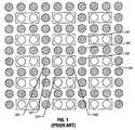
- One method of reducing unwanted signal deterioration from unwanted coupling between adjacent signalsmay be achieved by surrounding a particular signal conductor, or conductor pair in a differential system, with isolation areas such as ground pads that may substantially encircle a conductor or conductor pair. Such a system is illustrated in FIG. 1 .
- ground pads 101substantially encircle differential conductor pairs 103 .
- substantial isolation of the differential signal pair 103may be achieved from unwanted interference from nearby conductors such as the differential conductive pair 105 .
- the connector shown in FIG. 1provides only 30 signal conductors out of 100 contact pins that may be available. That is to say, in the example in FIG. 1, approximately 30 signal pins are available out of the 100 possible yielding an efficiency of only about 30%.
- FIG. 1illustrates an electrical interconnection method and connector
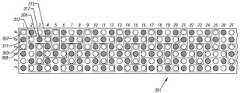
- FIG. 2illustrates a connection method and connector according to embodiments of the present invention
- FIG. 3illustrates a rectangular connector and connection method according to embodiments of the present invention
- FIG. 4illustrates a substantially square connector and connection method according to embodiments of the present invention.
- FIG. 5illustrates a high-density connector and connection method according to embodiments of the present invention.
- a 100 pin connector 201is illustrated having ten rows of ten conductors.
- the conductorsmay be configured as conductor pairs such as conductor pairs 203 and 205 .
- a conductor pairfor ease of illustration may be illustrated as two conductors within a rectangular box such as 203 and 205 as illustrated.
- Each conductor pairmay include two signal conductors.
- conductor pair 203may include a first conductor 207 and a second conductor 209 .
- conductor pair 205may include a first conductor 211 and a second conductor 213 .
- any coupling that may occurmay be disregarded by a differential signal receiver (not shown) that may typically reject common mode signals that maybe superimposed on the differential signal pairs. For example, if the signal on conductor 211 were to couple to the differential signal pair conductors 207 and 209 , because it is approximately equal distance between the two conductors 207 and 209 , any signal coupling would be approximately equal between conductors 207 and 209 . This coupling may be viewed as common mode noise or signals that may easily be rejected by differential receiver electronics (not illustrated).
- the signal conductors that may not be utilizedsuch as conductors 215 may be open conductors or coupled to a signal ground to provide additional isolation.
- a conductor having differential signal pairs as illustrated and described in association with FIG. 2has approximately an 82% utilization of available pins.
- FIG. 3a partial view of a 144 pin connector such as a Molex Corporation Model 73780 is illustrated having differential signals according to embodiments of the present invention.
- the connector 301may be organized as a connector of six rows (A-F) and a plurality of columns of which 27 ( 1 - 27 ) are illustrated.
- Triad 303has a first differential signal conductor 307 and a second signal conductor 309 and a signal ground connection 311 .
- signal triad 305includes a first conductor 313 , a second conductor 315 and a signal ground conductor 317 .
- the conductor triads 303 and 305are configured approximately orthogonal to each other such that signal conductor 313 is approximately equally spaced between signal conductors 309 and 307 . As was discussed in association with FIG. 2, any signal on conductor 313 may be coupled equally to conductors 307 and 309 (if at all) and therefore be rejected by differential receiving electronics (not shown) as common mode noise or signals.
- a central signal ground connectionsuch as 311 and 317 may serve to provide additional isolation between adjacent signal conductors adjacent to a connector triad such as conductor 313 . This additional isolation may reduce unwanted coupling when utilizing high speed signals.
- a connector configured as illustrated and described in association with FIG. 3,may provide 12 signal conductors for every four rows. This utilization will then be approximately 50% while at the same time providing for additional signal isolation.
- a 144 pin connector 401is illustrated utilizing differential signal triads such as triads 303 and 305 .
- the operation of the signal triadsis substantially as described in association with FIG. 3 .
- the configuration of connector 401may provide connections, in some embodiments, for 30 signal triads. This may provide for a high-density and low cost and low coupling connector as may be utilized for a pin grid array connector, BGA or pin connections to a circuit board.
- a 450 pin connectoris illustrated according to embodiments of the present invention.
- the connector pinsmay be organized to provide for differential signal pairs such as signal pair 503 and 505 .
- Differential signal pairs 503include two signal conductors 507 and 509 .
- differential signal pair 505includes two conductors 511 and 513 .
- the differential conductor pairs 503 and 505are organized generally orthogonally to each other such that adjacent contact such as contacts 507 is approximate equal distance between 513 and 511 .
- This organizationmay provide for a reduced interference level between adjacent connections for the reasons previously described.
- the unused pinsmay be connected to signal ground for impedance and signal isolation reasons. Configured as illustrated, connector 501 may provide for 210 differential pairs with reduced unwanted signal coupling.
Landscapes
- Physics & Mathematics (AREA)
- Engineering & Computer Science (AREA)
- Microelectronics & Electronic Packaging (AREA)
- Condensed Matter Physics & Semiconductors (AREA)
- General Physics & Mathematics (AREA)
- Computer Hardware Design (AREA)
- Power Engineering (AREA)
- Geometry (AREA)
- Electromagnetism (AREA)
- Details Of Connecting Devices For Male And Female Coupling (AREA)
Abstract
Description
Claims (13)
Priority Applications (1)
| Application Number | Priority Date | Filing Date | Title |
|---|---|---|---|
| US10/202,286US6641411B1 (en) | 2002-07-24 | 2002-07-24 | Low cost high speed connector |
Applications Claiming Priority (1)
| Application Number | Priority Date | Filing Date | Title |
|---|---|---|---|
| US10/202,286US6641411B1 (en) | 2002-07-24 | 2002-07-24 | Low cost high speed connector |
Publications (1)
| Publication Number | Publication Date |
|---|---|
| US6641411B1true US6641411B1 (en) | 2003-11-04 |
Family
ID=29270140
Family Applications (1)
| Application Number | Title | Priority Date | Filing Date |
|---|---|---|---|
| US10/202,286Expired - Fee RelatedUS6641411B1 (en) | 2002-07-24 | 2002-07-24 | Low cost high speed connector |
Country Status (1)
| Country | Link |
|---|---|
| US (1) | US6641411B1 (en) |
Cited By (54)
| Publication number | Priority date | Publication date | Assignee | Title |
|---|---|---|---|---|
| US6749468B2 (en) | 2001-11-28 | 2004-06-15 | Molex Incorporated | High-density connector assembly mounting apparatus |
| US20040203269A1 (en)* | 2003-04-09 | 2004-10-14 | Yazaki Corporation | Electrical connector |
| US20050212141A1 (en)* | 2004-03-29 | 2005-09-29 | Nec Electronics Corporation | Semiconductor appartus |
| US7217889B1 (en)* | 2003-12-04 | 2007-05-15 | Cisco Technology, Inc. | System and method for reducing crosstalk between vias in a printed circuit board |
| EP1815607A4 (en)* | 2004-11-17 | 2007-11-28 | Belden Cdt Canada Inc | Crosstalk reducing conductor and contact configuration in a communication system |
| WO2008054683A1 (en)* | 2006-10-30 | 2008-05-08 | Fci | Broadside-coupled signal pair configurations for electrical connectors |
| US20080214059A1 (en)* | 2007-03-02 | 2008-09-04 | Tyco Electronics Corporation | Orthogonal electrical connector with increased contact density |
| US20080293289A1 (en)* | 2004-11-17 | 2008-11-27 | Virak Siev | Balanced interconnector |
| US7497735B2 (en) | 2004-09-29 | 2009-03-03 | Fci Americas Technology, Inc. | High speed connectors that minimize signal skew and crosstalk |
| US7497736B2 (en) | 2006-12-19 | 2009-03-03 | Fci Americas Technology, Inc. | Shieldless, high-speed, low-cross-talk electrical connector |
| US7500871B2 (en) | 2006-08-21 | 2009-03-10 | Fci Americas Technology, Inc. | Electrical connector system with jogged contact tails |
| US20090117781A1 (en)* | 2007-11-07 | 2009-05-07 | Johnescu Douglas M | Electrical connector system with orthogonal contact tails |
| US20090191756A1 (en)* | 2003-09-26 | 2009-07-30 | Hull Gregory A | impedance mating interface for electrical connectors |
| US20090203238A1 (en)* | 2008-02-08 | 2009-08-13 | Fci Americas Technology, Inc. | Shared hole orthogonal footprints |
| JP2009534800A (en)* | 2006-04-25 | 2009-09-24 | ベルデン シーディーティー(カナダ)インコーポレイテッド | Balanced reciprocal connector |
| EP2175526A1 (en)* | 2008-10-13 | 2010-04-14 | Tyco Electronics Corporation | Connector assembly having signal and coaxial contacts |
| US7708569B2 (en) | 2006-10-30 | 2010-05-04 | Fci Americas Technology, Inc. | Broadside-coupled signal pair configurations for electrical connectors |
| US7713088B2 (en) | 2006-10-05 | 2010-05-11 | Fci | Broadside-coupled signal pair configurations for electrical connectors |
| US20100203765A1 (en)* | 2007-05-23 | 2010-08-12 | Thierry Goossens | Electrical connector with staggered single ended contacts |
| EP2109241A4 (en)* | 2007-03-05 | 2010-10-13 | Huawei Tech Co Ltd | ELECTRIC-OPTICAL CONVERSION MODULE, OPTICAL-ELECTRIC CONVERSION MODULE, AND CONVERSION METHOD |
| US7905751B1 (en) | 2009-09-23 | 2011-03-15 | Tyco Electronics Corporation | Electrical connector module with contacts of a differential pair held in separate chicklets |
| US20110081809A1 (en)* | 2009-10-01 | 2011-04-07 | Morgan Chad W | Printed circuit having ground vias between signal vias |
| US20110133254A1 (en)* | 2005-05-25 | 2011-06-09 | Zhaoqing Chen | Crosstalk reduction in electrical interconnects using differential signaling |
| US8137119B2 (en) | 2007-07-13 | 2012-03-20 | Fci Americas Technology Llc | Electrical connector system having a continuous ground at the mating interface thereof |
| US8267721B2 (en) | 2009-10-28 | 2012-09-18 | Fci Americas Technology Llc | Electrical connector having ground plates and ground coupling bar |
| US8540525B2 (en) | 2008-12-12 | 2013-09-24 | Molex Incorporated | Resonance modifying connector |
| US8545240B2 (en) | 2008-11-14 | 2013-10-01 | Molex Incorporated | Connector with terminals forming differential pairs |
| US8616919B2 (en) | 2009-11-13 | 2013-12-31 | Fci Americas Technology Llc | Attachment system for electrical connector |
| DE102005057905B4 (en)* | 2004-12-02 | 2014-05-22 | Tyco Electronics Corp. | Electrical connector |
| US8764464B2 (en) | 2008-02-29 | 2014-07-01 | Fci Americas Technology Llc | Cross talk reduction for high speed electrical connectors |
| EP2755457A1 (en)* | 2013-01-15 | 2014-07-16 | Fujitsu Limited | Printed circuit board and manufacturing method of printed circuit board |
| USD718253S1 (en) | 2012-04-13 | 2014-11-25 | Fci Americas Technology Llc | Electrical cable connector |
| US8905651B2 (en) | 2012-01-31 | 2014-12-09 | Fci | Dismountable optical coupling device |
| USD720698S1 (en) | 2013-03-15 | 2015-01-06 | Fci Americas Technology Llc | Electrical cable connector |
| US8944831B2 (en) | 2012-04-13 | 2015-02-03 | Fci Americas Technology Llc | Electrical connector having ribbed ground plate with engagement members |
| USD727268S1 (en) | 2012-04-13 | 2015-04-21 | Fci Americas Technology Llc | Vertical electrical connector |
| USD727852S1 (en) | 2012-04-13 | 2015-04-28 | Fci Americas Technology Llc | Ground shield for a right angle electrical connector |
| US20150130059A1 (en)* | 2013-11-14 | 2015-05-14 | Kabushiki Kaisha Toshiba | Semiconductor device and semiconductor package |
| US9048583B2 (en) | 2009-03-19 | 2015-06-02 | Fci Americas Technology Llc | Electrical connector having ribbed ground plate |
| USD733662S1 (en) | 2013-01-25 | 2015-07-07 | Fci Americas Technology Llc | Connector housing for electrical connector |
| US20150294945A1 (en)* | 2014-04-11 | 2015-10-15 | Qualcomm Incorporated | Apparatus and methods for shielding differential signal pin pairs |
| USD746236S1 (en) | 2012-07-11 | 2015-12-29 | Fci Americas Technology Llc | Electrical connector housing |
| US9257778B2 (en) | 2012-04-13 | 2016-02-09 | Fci Americas Technology | High speed electrical connector |
| US9277649B2 (en) | 2009-02-26 | 2016-03-01 | Fci Americas Technology Llc | Cross talk reduction for high-speed electrical connectors |
| EP2789057B1 (en)* | 2011-12-09 | 2016-03-09 | Rosenberger Hochfrequenztechnik GmbH & Co. KG | Method for manufacturing a plug connector |
| US20160150638A1 (en)* | 2014-11-24 | 2016-05-26 | International Business Machines Corporation | Interconnect array pattern with a 3:1 signal-to-ground ratio |
| US9425149B1 (en)* | 2013-11-22 | 2016-08-23 | Altera Corporation | Integrated circuit package routing with reduced crosstalk |
| US9520661B1 (en)* | 2015-08-25 | 2016-12-13 | Tyco Electronics Corporation | Electrical connector assembly |
| US9543703B2 (en) | 2012-07-11 | 2017-01-10 | Fci Americas Technology Llc | Electrical connector with reduced stack height |
| US9554454B2 (en)* | 2014-12-17 | 2017-01-24 | Intel Corporation | Devices and methods to reduce differential signal pair crosstalk |
| US20170117199A1 (en)* | 2012-02-10 | 2017-04-27 | Taiwan Semiconductor Manufacturing Company, Ltd. | Semiconductor devices with bump allocation |
| US9955605B2 (en)* | 2016-03-30 | 2018-04-24 | Intel Corporation | Hardware interface with space-efficient cell pattern |
| US10454218B2 (en)* | 2017-08-14 | 2019-10-22 | Foxconn Interconnect Technology Limited | Electrical connector and method making the same |
| US20200105650A1 (en)* | 2018-09-28 | 2020-04-02 | Juniper Networks, Inc. | Multi-pitch ball grid array |
Citations (5)
| Publication number | Priority date | Publication date | Assignee | Title |
|---|---|---|---|---|
| US5145387A (en)* | 1990-07-30 | 1992-09-08 | Advantest Corporation | High-frequency multi-pin connector |
| US5174770A (en)* | 1990-11-15 | 1992-12-29 | Amp Incorporated | Multicontact connector for signal transmission |
| US5224867A (en)* | 1990-10-08 | 1993-07-06 | Daiichi Denshi Kogyo Kabushiki Kaisha | Electrical connector for coaxial flat cable |
| US5399104A (en)* | 1992-09-28 | 1995-03-21 | Mckenzie Socket Technology, Inc. | Socket for multi-lead integrated circuit packages |
| US5525067A (en)* | 1994-02-03 | 1996-06-11 | Motorola, Inc | Ground plane interconnection system using multiple connector contacts |
- 2002
- 2002-07-24USUS10/202,286patent/US6641411B1/ennot_activeExpired - Fee Related
Patent Citations (5)
| Publication number | Priority date | Publication date | Assignee | Title |
|---|---|---|---|---|
| US5145387A (en)* | 1990-07-30 | 1992-09-08 | Advantest Corporation | High-frequency multi-pin connector |
| US5224867A (en)* | 1990-10-08 | 1993-07-06 | Daiichi Denshi Kogyo Kabushiki Kaisha | Electrical connector for coaxial flat cable |
| US5174770A (en)* | 1990-11-15 | 1992-12-29 | Amp Incorporated | Multicontact connector for signal transmission |
| US5399104A (en)* | 1992-09-28 | 1995-03-21 | Mckenzie Socket Technology, Inc. | Socket for multi-lead integrated circuit packages |
| US5525067A (en)* | 1994-02-03 | 1996-06-11 | Motorola, Inc | Ground plane interconnection system using multiple connector contacts |
Cited By (109)
| Publication number | Priority date | Publication date | Assignee | Title |
|---|---|---|---|---|
| US6749468B2 (en) | 2001-11-28 | 2004-06-15 | Molex Incorporated | High-density connector assembly mounting apparatus |
| US20040203269A1 (en)* | 2003-04-09 | 2004-10-14 | Yazaki Corporation | Electrical connector |
| US7066744B2 (en)* | 2003-04-09 | 2006-06-27 | Yazaki Corporation | Electrical connector |
| US7837504B2 (en) | 2003-09-26 | 2010-11-23 | Fci Americas Technology, Inc. | Impedance mating interface for electrical connectors |
| US20090191756A1 (en)* | 2003-09-26 | 2009-07-30 | Hull Gregory A | impedance mating interface for electrical connectors |
| US7217889B1 (en)* | 2003-12-04 | 2007-05-15 | Cisco Technology, Inc. | System and method for reducing crosstalk between vias in a printed circuit board |
| US20050212141A1 (en)* | 2004-03-29 | 2005-09-29 | Nec Electronics Corporation | Semiconductor appartus |
| US7335992B2 (en)* | 2004-03-29 | 2008-02-26 | Nec Electronics Corporation | Semiconductor apparatus with improved yield |
| US7497735B2 (en) | 2004-09-29 | 2009-03-03 | Fci Americas Technology, Inc. | High speed connectors that minimize signal skew and crosstalk |
| US7614901B1 (en) | 2004-11-17 | 2009-11-10 | Belden Cdt (Canada) Inc. | Balanced interconnector |
| US20090225979A1 (en)* | 2004-11-17 | 2009-09-10 | Belden Cdt (Canada) Inc. | Crosstalk Reducing Conductor and Contact Configuration in a Communication System |
| US20080293289A1 (en)* | 2004-11-17 | 2008-11-27 | Virak Siev | Balanced interconnector |
| EP1815607A4 (en)* | 2004-11-17 | 2007-11-28 | Belden Cdt Canada Inc | Crosstalk reducing conductor and contact configuration in a communication system |
| US8958545B2 (en) | 2004-11-17 | 2015-02-17 | Belden Cdt (Canada) Inc. | Crosstalk reducing conductor and contact configuration in a communication system |
| EP2395676A1 (en)* | 2004-11-17 | 2011-12-14 | Belden CDT (Canada) Inc. | Crosstalk reducing connector and contact configuration in a communication system |
| US8477928B2 (en) | 2004-11-17 | 2013-07-02 | Belden Cdt (Canada) Inc. | Crosstalk reducing conductor and contact configuration in a communication system |
| US7568938B2 (en) | 2004-11-17 | 2009-08-04 | Belden Cdt (Canada) Inc. | Balanced interconnector |
| US20090269969A1 (en)* | 2004-11-17 | 2009-10-29 | Belden Cdt (Canada) Inc. | Balanced interconnector |
| DE102005057905B4 (en)* | 2004-12-02 | 2014-05-22 | Tyco Electronics Corp. | Electrical connector |
| US8203206B2 (en)* | 2005-05-25 | 2012-06-19 | International Business Machines Corporation | Crosstalk reduction in electrical interconnects using differential signaling |
| US20110133254A1 (en)* | 2005-05-25 | 2011-06-09 | Zhaoqing Chen | Crosstalk reduction in electrical interconnects using differential signaling |
| JP2009534800A (en)* | 2006-04-25 | 2009-09-24 | ベルデン シーディーティー(カナダ)インコーポレイテッド | Balanced reciprocal connector |
| US7500871B2 (en) | 2006-08-21 | 2009-03-10 | Fci Americas Technology, Inc. | Electrical connector system with jogged contact tails |
| US7837505B2 (en) | 2006-08-21 | 2010-11-23 | Fci Americas Technology Llc | Electrical connector system with jogged contact tails |
| US7713088B2 (en) | 2006-10-05 | 2010-05-11 | Fci | Broadside-coupled signal pair configurations for electrical connectors |
| CN101536259B (en)* | 2006-10-30 | 2011-11-09 | Fci公司 | electrical connector |
| WO2008054683A1 (en)* | 2006-10-30 | 2008-05-08 | Fci | Broadside-coupled signal pair configurations for electrical connectors |
| US7708569B2 (en) | 2006-10-30 | 2010-05-04 | Fci Americas Technology, Inc. | Broadside-coupled signal pair configurations for electrical connectors |
| CN102064406B (en)* | 2006-10-30 | 2013-07-31 | Fci公司 | Broadside coupled signal pair configuration for electrical connectors |
| US8678860B2 (en) | 2006-12-19 | 2014-03-25 | Fci Americas Technology Llc | Shieldless, high-speed, low-cross-talk electrical connector |
| US8096832B2 (en) | 2006-12-19 | 2012-01-17 | Fci Americas Technology Llc | Shieldless, high-speed, low-cross-talk electrical connector |
| US7497736B2 (en) | 2006-12-19 | 2009-03-03 | Fci Americas Technology, Inc. | Shieldless, high-speed, low-cross-talk electrical connector |
| US7762843B2 (en) | 2006-12-19 | 2010-07-27 | Fci Americas Technology, Inc. | Shieldless, high-speed, low-cross-talk electrical connector |
| US8382521B2 (en) | 2006-12-19 | 2013-02-26 | Fci Americas Technology Llc | Shieldless, high-speed, low-cross-talk electrical connector |
| WO2008108951A3 (en)* | 2007-03-02 | 2008-12-04 | Tyco Electronics Corp | Orthogonal electrical connector with increased contact density |
| US20080214059A1 (en)* | 2007-03-02 | 2008-09-04 | Tyco Electronics Corporation | Orthogonal electrical connector with increased contact density |
| EP2109241A4 (en)* | 2007-03-05 | 2010-10-13 | Huawei Tech Co Ltd | ELECTRIC-OPTICAL CONVERSION MODULE, OPTICAL-ELECTRIC CONVERSION MODULE, AND CONVERSION METHOD |
| US8550852B2 (en) | 2007-05-23 | 2013-10-08 | Fci | Electrical connector with staggered single ended contacts |
| US20100203765A1 (en)* | 2007-05-23 | 2010-08-12 | Thierry Goossens | Electrical connector with staggered single ended contacts |
| US8137119B2 (en) | 2007-07-13 | 2012-03-20 | Fci Americas Technology Llc | Electrical connector system having a continuous ground at the mating interface thereof |
| US20090117781A1 (en)* | 2007-11-07 | 2009-05-07 | Johnescu Douglas M | Electrical connector system with orthogonal contact tails |
| US8251745B2 (en) | 2007-11-07 | 2012-08-28 | Fci Americas Technology Llc | Electrical connector system with orthogonal contact tails |
| US7666009B2 (en)* | 2008-02-08 | 2010-02-23 | Fci Americas Technology, Inc. | Shared hole orthogonal footprints |
| US20090203238A1 (en)* | 2008-02-08 | 2009-08-13 | Fci Americas Technology, Inc. | Shared hole orthogonal footprints |
| US8764464B2 (en) | 2008-02-29 | 2014-07-01 | Fci Americas Technology Llc | Cross talk reduction for high speed electrical connectors |
| EP2175526A1 (en)* | 2008-10-13 | 2010-04-14 | Tyco Electronics Corporation | Connector assembly having signal and coaxial contacts |
| US8545240B2 (en) | 2008-11-14 | 2013-10-01 | Molex Incorporated | Connector with terminals forming differential pairs |
| US8992237B2 (en) | 2008-12-12 | 2015-03-31 | Molex Incorporated | Resonance modifying connector |
| US8540525B2 (en) | 2008-12-12 | 2013-09-24 | Molex Incorporated | Resonance modifying connector |
| US8651881B2 (en) | 2008-12-12 | 2014-02-18 | Molex Incorporated | Resonance modifying connector |
| US9277649B2 (en) | 2009-02-26 | 2016-03-01 | Fci Americas Technology Llc | Cross talk reduction for high-speed electrical connectors |
| US10720721B2 (en) | 2009-03-19 | 2020-07-21 | Fci Usa Llc | Electrical connector having ribbed ground plate |
| US9461410B2 (en) | 2009-03-19 | 2016-10-04 | Fci Americas Technology Llc | Electrical connector having ribbed ground plate |
| US9048583B2 (en) | 2009-03-19 | 2015-06-02 | Fci Americas Technology Llc | Electrical connector having ribbed ground plate |
| US10096921B2 (en) | 2009-03-19 | 2018-10-09 | Fci Usa Llc | Electrical connector having ribbed ground plate |
| US20110070753A1 (en)* | 2009-09-23 | 2011-03-24 | Tyco Electronics Corporation | Electrical connector module with contacts of a differential pair held in separate chicklets |
| US7905751B1 (en) | 2009-09-23 | 2011-03-15 | Tyco Electronics Corporation | Electrical connector module with contacts of a differential pair held in separate chicklets |
| US20110081809A1 (en)* | 2009-10-01 | 2011-04-07 | Morgan Chad W | Printed circuit having ground vias between signal vias |
| CN102036469B (en)* | 2009-10-01 | 2015-07-08 | 泰科电子公司 | Printed circuit having ground vias between signal vias |
| CN102036469A (en)* | 2009-10-01 | 2011-04-27 | 泰科电子公司 | Printed circuit having ground vias between signal vias |
| US8080738B2 (en) | 2009-10-01 | 2011-12-20 | Tyco Electronics Corporation | Printed circuit having ground vias between signal vias |
| US8267721B2 (en) | 2009-10-28 | 2012-09-18 | Fci Americas Technology Llc | Electrical connector having ground plates and ground coupling bar |
| US8616919B2 (en) | 2009-11-13 | 2013-12-31 | Fci Americas Technology Llc | Attachment system for electrical connector |
| EP2789057B1 (en)* | 2011-12-09 | 2016-03-09 | Rosenberger Hochfrequenztechnik GmbH & Co. KG | Method for manufacturing a plug connector |
| US9490601B2 (en) | 2011-12-09 | 2016-11-08 | Rosenberger Hochfrequenztechnik Gmbh & Co. Kg | Method of manufacturing an insertion-type connector |
| US10170881B2 (en) | 2011-12-09 | 2019-01-01 | Rosenberger Hochfrequenztechnik Gmbh & Co. Kg | Method of manufacturing an insertion-type connector |
| US8905651B2 (en) | 2012-01-31 | 2014-12-09 | Fci | Dismountable optical coupling device |
| US20170117199A1 (en)* | 2012-02-10 | 2017-04-27 | Taiwan Semiconductor Manufacturing Company, Ltd. | Semiconductor devices with bump allocation |
| US10541185B2 (en)* | 2012-02-10 | 2020-01-21 | Taiwan Semiconductor Manufacturing Company, Ltd. | Semiconductor devices with bump allocation |
| USD748063S1 (en) | 2012-04-13 | 2016-01-26 | Fci Americas Technology Llc | Electrical ground shield |
| USD790471S1 (en) | 2012-04-13 | 2017-06-27 | Fci Americas Technology Llc | Vertical electrical connector |
| US8944831B2 (en) | 2012-04-13 | 2015-02-03 | Fci Americas Technology Llc | Electrical connector having ribbed ground plate with engagement members |
| USD718253S1 (en) | 2012-04-13 | 2014-11-25 | Fci Americas Technology Llc | Electrical cable connector |
| US9257778B2 (en) | 2012-04-13 | 2016-02-09 | Fci Americas Technology | High speed electrical connector |
| USD750025S1 (en) | 2012-04-13 | 2016-02-23 | Fci Americas Technology Llc | Vertical electrical connector |
| USD750030S1 (en) | 2012-04-13 | 2016-02-23 | Fci Americas Technology Llc | Electrical cable connector |
| USD727852S1 (en) | 2012-04-13 | 2015-04-28 | Fci Americas Technology Llc | Ground shield for a right angle electrical connector |
| US9831605B2 (en) | 2012-04-13 | 2017-11-28 | Fci Americas Technology Llc | High speed electrical connector |
| USD727268S1 (en) | 2012-04-13 | 2015-04-21 | Fci Americas Technology Llc | Vertical electrical connector |
| USD816044S1 (en) | 2012-04-13 | 2018-04-24 | Fci Americas Technology Llc | Electrical cable connector |
| US9543703B2 (en) | 2012-07-11 | 2017-01-10 | Fci Americas Technology Llc | Electrical connector with reduced stack height |
| USD751507S1 (en) | 2012-07-11 | 2016-03-15 | Fci Americas Technology Llc | Electrical connector |
| US9871323B2 (en) | 2012-07-11 | 2018-01-16 | Fci Americas Technology Llc | Electrical connector with reduced stack height |
| USD746236S1 (en) | 2012-07-11 | 2015-12-29 | Fci Americas Technology Llc | Electrical connector housing |
| EP2755457A1 (en)* | 2013-01-15 | 2014-07-16 | Fujitsu Limited | Printed circuit board and manufacturing method of printed circuit board |
| CN103929877A (en)* | 2013-01-15 | 2014-07-16 | 富士通株式会社 | Printed circuit board and method for manufacturing printed circuit board |
| USD733662S1 (en) | 2013-01-25 | 2015-07-07 | Fci Americas Technology Llc | Connector housing for electrical connector |
| USD745852S1 (en) | 2013-01-25 | 2015-12-22 | Fci Americas Technology Llc | Electrical connector |
| USD772168S1 (en) | 2013-01-25 | 2016-11-22 | Fci Americas Technology Llc | Connector housing for electrical connector |
| USD766832S1 (en) | 2013-01-25 | 2016-09-20 | Fci Americas Technology Llc | Electrical connector |
| USD720698S1 (en) | 2013-03-15 | 2015-01-06 | Fci Americas Technology Llc | Electrical cable connector |
| US10566274B2 (en) | 2013-11-14 | 2020-02-18 | Toshiba Memory Corporation | Semiconductor device and semiconductor package including plural solder ball sets each corresponding to a pair of differential input and differential output signals |
| US20150130059A1 (en)* | 2013-11-14 | 2015-05-14 | Kabushiki Kaisha Toshiba | Semiconductor device and semiconductor package |
| US10090235B2 (en)* | 2013-11-14 | 2018-10-02 | Toshiba Memory Corporation | Semiconductor device and semiconductor package |
| US9425149B1 (en)* | 2013-11-22 | 2016-08-23 | Altera Corporation | Integrated circuit package routing with reduced crosstalk |
| US9514966B2 (en)* | 2014-04-11 | 2016-12-06 | Qualcomm Incorporated | Apparatus and methods for shielding differential signal pin pairs |
| US20150294945A1 (en)* | 2014-04-11 | 2015-10-15 | Qualcomm Incorporated | Apparatus and methods for shielding differential signal pin pairs |
| US9972566B2 (en) | 2014-11-24 | 2018-05-15 | International Business Machines Corporation | Interconnect array pattern with a 3:1 signal-to-ground ratio |
| US9646925B2 (en) | 2014-11-24 | 2017-05-09 | International Business Machines Corporation | Interconnect array pattern with a 3:1 signal-to-ground ratio |
| US9543241B2 (en)* | 2014-11-24 | 2017-01-10 | International Business Machines Corporation | Interconnect array pattern with a 3:1 signal-to-ground ratio |
| US20160150638A1 (en)* | 2014-11-24 | 2016-05-26 | International Business Machines Corporation | Interconnect array pattern with a 3:1 signal-to-ground ratio |
| US9554454B2 (en)* | 2014-12-17 | 2017-01-24 | Intel Corporation | Devices and methods to reduce differential signal pair crosstalk |
| US9520661B1 (en)* | 2015-08-25 | 2016-12-13 | Tyco Electronics Corporation | Electrical connector assembly |
| US9955605B2 (en)* | 2016-03-30 | 2018-04-24 | Intel Corporation | Hardware interface with space-efficient cell pattern |
| US10454218B2 (en)* | 2017-08-14 | 2019-10-22 | Foxconn Interconnect Technology Limited | Electrical connector and method making the same |
| US20200105650A1 (en)* | 2018-09-28 | 2020-04-02 | Juniper Networks, Inc. | Multi-pitch ball grid array |
| US10840173B2 (en)* | 2018-09-28 | 2020-11-17 | Juniper Networks, Inc. | Multi-pitch ball grid array |
| US11652035B2 (en) | 2018-09-28 | 2023-05-16 | Juniper Networks, Inc. | Multi-pitch ball grid array |
| US12288741B2 (en) | 2018-09-28 | 2025-04-29 | Juniper Networks, Inc. | Multi-pitch ball grid array |
Similar Documents
| Publication | Publication Date | Title |
|---|---|---|
| US6641411B1 (en) | Low cost high speed connector | |
| US6717825B2 (en) | Electrical connection system for two printed circuit boards mounted on opposite sides of a mid-plane printed circuit board at angles to each other | |
| US6270381B1 (en) | Crosstalk compensation for electrical connectors | |
| US6524119B2 (en) | Connector adapted to handling of different kinds of signals including high-speed signals | |
| US5908333A (en) | Connector with integral transmission line bus | |
| EP1239552B1 (en) | Connector having signal contacts and ground contacts in a specific arrangement | |
| US5530623A (en) | High speed memory packaging scheme | |
| RU2013897C1 (en) | Electronic system | |
| US6574115B2 (en) | Computer system, electronic circuit board, and card | |
| US7128611B2 (en) | Electric connector including signal contact pairs and ground contacts provided in rows at a first end, in which the ground contacts are provided between signal contact pairs from the respective rows at a second end | |
| US6422876B1 (en) | High throughput interconnection system using orthogonal connectors | |
| JPH07111891B2 (en) | Packaging system | |
| US20070232089A1 (en) | Bridge modules for connecting plural groups of electronic modules | |
| US6176743B1 (en) | Electrical adapter | |
| EP1049217A1 (en) | Connector having internal crosstalk compensation | |
| US7744420B2 (en) | Connector system for connecting a first part and a second part, connector assembly and device board | |
| US6908340B1 (en) | Method and system for reducing crosstalk in a backplane | |
| US20020130728A1 (en) | Electrical connector and transmission line | |
| JP2023532260A (en) | Printed circuit board and electronic equipment comprising the printed circuit board | |
| US6350130B1 (en) | Electrically coupling an avionics line replaceable unit with an avionics test station | |
| US6578103B1 (en) | Compact PCI backplane and method of data transfer across the compact PCI backplane | |
| US7128616B1 (en) | High speed data transmission cable connector system | |
| US6929482B2 (en) | Interconnection arrangement | |
| JP2587316B2 (en) | Multi-pole electrical connector for coaxial flat cable | |
| US6379193B1 (en) | Substrate connector assembly for a computer system |
Legal Events
| Date | Code | Title | Description |
|---|---|---|---|
| AS | Assignment | Owner name:MAXXAN SYSTEMS, INC., CALIFORNIA Free format text:ASSIGNMENT OF ASSIGNORS INTEREST;ASSIGNORS:STODDARD, DONALD J.;SCHUMACHER, MATTHEW J.;REEL/FRAME:013144/0299;SIGNING DATES FROM 20020722 TO 20020723 | |
| REMI | Maintenance fee reminder mailed | ||
| REIN | Reinstatement after maintenance fee payment confirmed | ||
| FEPP | Fee payment procedure | Free format text:PETITION RELATED TO MAINTENANCE FEES GRANTED (ORIGINAL EVENT CODE: PMFG); ENTITY STATUS OF PATENT OWNER: SMALL ENTITY Free format text:PETITION RELATED TO MAINTENANCE FEES FILED (ORIGINAL EVENT CODE: PMFP); ENTITY STATUS OF PATENT OWNER: SMALL ENTITY | |
| FP | Lapsed due to failure to pay maintenance fee | Effective date:20071104 | |
| PRDP | Patent reinstated due to the acceptance of a late maintenance fee | Effective date:20080807 | |
| FPAY | Fee payment | Year of fee payment:4 | |
| SULP | Surcharge for late payment | ||
| AS | Assignment | Owner name:CIPHERMAX, INCORPORATED, TEXAS Free format text:CHANGE OF NAME;ASSIGNOR:MAXXAN SYSTEMS, INCORPORATED;REEL/FRAME:022390/0701 Effective date:20070117 | |
| REMI | Maintenance fee reminder mailed | ||
| FPAY | Fee payment | Year of fee payment:8 | |
| SULP | Surcharge for late payment | Year of fee payment:7 | |
| AS | Assignment | Owner name:SAICO INFORMATION TECHNOLOGY (WUHAN) CO., LTD., CH Free format text:ASSIGNMENT OF ASSIGNORS INTEREST;ASSIGNOR:CIPHERMAX, INC.;REEL/FRAME:028592/0887 Effective date:20120614 | |
| REMI | Maintenance fee reminder mailed | ||
| LAPS | Lapse for failure to pay maintenance fees | ||
| STCH | Information on status: patent discontinuation | Free format text:PATENT EXPIRED DUE TO NONPAYMENT OF MAINTENANCE FEES UNDER 37 CFR 1.362 | |
| FP | Lapsed due to failure to pay maintenance fee | Effective date:20151104 |