US6640999B2 - Dose dispensing pump for dispensing two or more materials - Google Patents
Dose dispensing pump for dispensing two or more materialsDownload PDFInfo
- Publication number
- US6640999B2 US6640999B2US10/054,511US5451101AUS6640999B2US 6640999 B2US6640999 B2US 6640999B2US 5451101 AUS5451101 AUS 5451101AUS 6640999 B2US6640999 B2US 6640999B2
- Authority
- US
- United States
- Prior art keywords
- dispensing
- valve means
- pump
- liquid
- paste
- Prior art date
- Legal status (The legal status is an assumption and is not a legal conclusion. Google has not performed a legal analysis and makes no representation as to the accuracy of the status listed.)
- Expired - Lifetime, expires
Links
- 239000000463materialSubstances0.000titleclaimsdescription28
- 239000007788liquidSubstances0.000claimsabstractdescription57
- 239000000499gelSubstances0.000claimsabstractdescription43
- 239000002002slurrySubstances0.000claimsabstractdescription43
- 230000000712assemblyEffects0.000claimsabstractdescription7
- 238000000429assemblyMethods0.000claimsabstractdescription7
- 238000004891communicationMethods0.000claimsdescription29
- 239000012530fluidSubstances0.000claimsdescription16
- 238000000034methodMethods0.000claimsdescription3
- 230000001590oxidative effectEffects0.000claimsdescription3
- 239000000118hair dyeSubstances0.000claimsdescription2
- 230000009972noncorrosive effectEffects0.000claims1
- 239000000203mixtureSubstances0.000description7
- XLYOFNOQVPJJNP-UHFFFAOYSA-NwaterChemical compoundOXLYOFNOQVPJJNP-UHFFFAOYSA-N0.000description5
- 230000009969flowable effectEffects0.000description4
- BXWNKGSJHAJOGX-UHFFFAOYSA-Nhexadecan-1-olChemical compoundCCCCCCCCCCCCCCCCOBXWNKGSJHAJOGX-UHFFFAOYSA-N0.000description4
- GLDOVTGHNKAZLK-UHFFFAOYSA-Noctadecan-1-olChemical compoundCCCCCCCCCCCCCCCCCCOGLDOVTGHNKAZLK-UHFFFAOYSA-N0.000description4
- 238000007789sealingMethods0.000description4
- HEMHJVSKTPXQMS-UHFFFAOYSA-MSodium hydroxideChemical compound[OH-].[Na+]HEMHJVSKTPXQMS-UHFFFAOYSA-M0.000description3
- KRKNYBCHXYNGOX-UHFFFAOYSA-Ncitric acidChemical compoundOC(=O)CC(O)(C(O)=O)CC(O)=OKRKNYBCHXYNGOX-UHFFFAOYSA-N0.000description3
- 229920001971elastomerPolymers0.000description3
- 230000037308hair colorEffects0.000description3
- 239000006072pasteSubstances0.000description3
- 239000004033plasticSubstances0.000description3
- 229920003023plasticPolymers0.000description3
- CDAWCLOXVUBKRW-UHFFFAOYSA-N2-aminophenolChemical compoundNC1=CC=CC=C1OCDAWCLOXVUBKRW-UHFFFAOYSA-N0.000description2
- CWLKGDAVCFYWJK-UHFFFAOYSA-N3-aminophenolChemical compoundNC1=CC=CC(O)=C1CWLKGDAVCFYWJK-UHFFFAOYSA-N0.000description2
- 239000003109Disodium ethylene diamine tetraacetateSubstances0.000description2
- ZGTMUACCHSMWAC-UHFFFAOYSA-LEDTA disodium salt (anhydrous)Chemical compound[Na+].[Na+].OC(=O)CN(CC([O-])=O)CCN(CC(O)=O)CC([O-])=OZGTMUACCHSMWAC-UHFFFAOYSA-L0.000description2
- MHAJPDPJQMAIIY-UHFFFAOYSA-NHydrogen peroxideChemical compoundOOMHAJPDPJQMAIIY-UHFFFAOYSA-N0.000description2
- 239000011324beadSubstances0.000description2
- 229940073669ceteareth 20Drugs0.000description2
- 229960000541cetyl alcoholDrugs0.000description2
- 230000006835compressionEffects0.000description2
- 238000007906compressionMethods0.000description2
- 238000005520cutting processMethods0.000description2
- ZCPCLAPUXMZUCD-UHFFFAOYSA-Mdihexadecyl(dimethyl)azanium;chlorideChemical compound[Cl-].CCCCCCCCCCCCCCCC[N+](C)(C)CCCCCCCCCCCCCCCCZCPCLAPUXMZUCD-UHFFFAOYSA-M0.000description2
- 229940057204dimethicone 100Drugs0.000description2
- 235000019301disodium ethylene diamine tetraacetateNutrition0.000description2
- WSDISUOETYTPRL-UHFFFAOYSA-Ndmdm hydantoinChemical compoundCC1(C)N(CO)C(=O)N(CO)C1=OWSDISUOETYTPRL-UHFFFAOYSA-N0.000description2
- 239000000806elastomerSubstances0.000description2
- 239000003205fragranceSubstances0.000description2
- 239000002184metalSubstances0.000description2
- 229910052751metalInorganic materials0.000description2
- 150000002739metalsChemical class0.000description2
- 229940049292n-(3-(dimethylamino)propyl)octadecanamideDrugs0.000description2
- WWVIUVHFPSALDO-UHFFFAOYSA-Nn-[3-(dimethylamino)propyl]octadecanamideChemical compoundCCCCCCCCCCCCCCCCCC(=O)NCCCN(C)CWWVIUVHFPSALDO-UHFFFAOYSA-N0.000description2
- GOQYKNQRPGWPLP-UHFFFAOYSA-Nn-heptadecyl alcoholNatural productsCCCCCCCCCCCCCCCCCOGOQYKNQRPGWPLP-UHFFFAOYSA-N0.000description2
- 230000037361pathwayEffects0.000description2
- 229920001296polysiloxanePolymers0.000description2
- 238000005086pumpingMethods0.000description2
- GHMLBKRAJCXXBS-UHFFFAOYSA-NresorcinolChemical compoundOC1=CC=CC(O)=C1GHMLBKRAJCXXBS-UHFFFAOYSA-N0.000description2
- CBCKQZAAMUWICA-UHFFFAOYSA-N1,4-phenylenediamineChemical compoundNC1=CC=C(N)C=C1CBCKQZAAMUWICA-UHFFFAOYSA-N0.000description1
- 2299400185633-aminophenolDrugs0.000description1
- KJLPSBMDOIVXSN-UHFFFAOYSA-N4-[4-[2-[4-(3,4-dicarboxyphenoxy)phenyl]propan-2-yl]phenoxy]phthalic acidChemical groupC=1C=C(OC=2C=C(C(C(O)=O)=CC=2)C(O)=O)C=CC=1C(C)(C)C(C=C1)=CC=C1OC1=CC=C(C(O)=O)C(C(O)=O)=C1KJLPSBMDOIVXSN-UHFFFAOYSA-N0.000description1
- QYYMDNHUJFIDDQ-UHFFFAOYSA-N5-chloro-2-methyl-1,2-thiazol-3-one;2-methyl-1,2-thiazol-3-oneChemical compoundCN1SC=CC1=O.CN1SC(Cl)=CC1=OQYYMDNHUJFIDDQ-UHFFFAOYSA-N0.000description1
- 229920001875EbonitePolymers0.000description1
- 244000273618Sphenoclea zeylanicaSpecies0.000description1
- 239000002253acidSubstances0.000description1
- 230000015556catabolic processEffects0.000description1
- 239000003795chemical substances by applicationSubstances0.000description1
- 230000003750conditioning effectEffects0.000description1
- 238000010276constructionMethods0.000description1
- 239000002537cosmeticSubstances0.000description1
- 238000007599dischargingMethods0.000description1
- 239000000975dyeSubstances0.000description1
- 230000000694effectsEffects0.000description1
- 229920002457flexible plasticPolymers0.000description1
- 239000003292glueSubstances0.000description1
- 238000001746injection mouldingMethods0.000description1
- 230000003993interactionEffects0.000description1
- 239000012528membraneSubstances0.000description1
- 238000005058metal castingMethods0.000description1
- 238000012986modificationMethods0.000description1
- 230000004048modificationEffects0.000description1
- 150000002978peroxidesChemical class0.000description1
- 238000002360preparation methodMethods0.000description1
- HRZFUMHJMZEROT-UHFFFAOYSA-Lsodium disulfiteChemical compound[Na+].[Na+].[O-]S(=O)S([O-])(=O)=OHRZFUMHJMZEROT-UHFFFAOYSA-L0.000description1
- 229940001584sodium metabisulfiteDrugs0.000description1
- 235000010262sodium metabisulphiteNutrition0.000description1
- 239000007921spraySubstances0.000description1
- 238000005507sprayingMethods0.000description1
- 239000000126substanceSubstances0.000description1
Images


Classifications
- B—PERFORMING OPERATIONS; TRANSPORTING
- B05—SPRAYING OR ATOMISING IN GENERAL; APPLYING FLUENT MATERIALS TO SURFACES, IN GENERAL
- B05B—SPRAYING APPARATUS; ATOMISING APPARATUS; NOZZLES
- B05B11/00—Single-unit hand-held apparatus in which flow of contents is produced by the muscular force of the operator at the moment of use
- B05B11/0005—Components or details
- B05B11/0078—Arrangements for separately storing several components
- B—PERFORMING OPERATIONS; TRANSPORTING
- B05—SPRAYING OR ATOMISING IN GENERAL; APPLYING FLUENT MATERIALS TO SURFACES, IN GENERAL
- B05B—SPRAYING APPARATUS; ATOMISING APPARATUS; NOZZLES
- B05B11/00—Single-unit hand-held apparatus in which flow of contents is produced by the muscular force of the operator at the moment of use
- B05B11/01—Single-unit hand-held apparatus in which flow of contents is produced by the muscular force of the operator at the moment of use characterised by the means producing the flow
- B05B11/10—Pump arrangements for transferring the contents from the container to a pump chamber by a sucking effect and forcing the contents out through the dispensing nozzle
- B05B11/1001—Piston pumps
- B05B11/1015—Piston pumps actuated without substantial movement of the nozzle in the direction of the pressure stroke
- B—PERFORMING OPERATIONS; TRANSPORTING
- B05—SPRAYING OR ATOMISING IN GENERAL; APPLYING FLUENT MATERIALS TO SURFACES, IN GENERAL
- B05B—SPRAYING APPARATUS; ATOMISING APPARATUS; NOZZLES
- B05B11/00—Single-unit hand-held apparatus in which flow of contents is produced by the muscular force of the operator at the moment of use
- B05B11/01—Single-unit hand-held apparatus in which flow of contents is produced by the muscular force of the operator at the moment of use characterised by the means producing the flow
- B05B11/10—Pump arrangements for transferring the contents from the container to a pump chamber by a sucking effect and forcing the contents out through the dispensing nozzle
- B05B11/1042—Components or details
- B05B11/1064—Pump inlet and outlet valve elements integrally formed of a deformable material
- B—PERFORMING OPERATIONS; TRANSPORTING
- B05—SPRAYING OR ATOMISING IN GENERAL; APPLYING FLUENT MATERIALS TO SURFACES, IN GENERAL
- B05B—SPRAYING APPARATUS; ATOMISING APPARATUS; NOZZLES
- B05B11/00—Single-unit hand-held apparatus in which flow of contents is produced by the muscular force of the operator at the moment of use
- B05B11/01—Single-unit hand-held apparatus in which flow of contents is produced by the muscular force of the operator at the moment of use characterised by the means producing the flow
- B05B11/10—Pump arrangements for transferring the contents from the container to a pump chamber by a sucking effect and forcing the contents out through the dispensing nozzle
- B05B11/1081—Arrangements for pumping several liquids or other fluent materials from several containers, e.g. for mixing them at the moment of pumping
- B05B11/1084—Arrangements for pumping several liquids or other fluent materials from several containers, e.g. for mixing them at the moment of pumping each liquid or other fluent material being pumped by a separate pump
- B—PERFORMING OPERATIONS; TRANSPORTING
- B05—SPRAYING OR ATOMISING IN GENERAL; APPLYING FLUENT MATERIALS TO SURFACES, IN GENERAL
- B05B—SPRAYING APPARATUS; ATOMISING APPARATUS; NOZZLES
- B05B11/00—Single-unit hand-held apparatus in which flow of contents is produced by the muscular force of the operator at the moment of use
- B05B11/01—Single-unit hand-held apparatus in which flow of contents is produced by the muscular force of the operator at the moment of use characterised by the means producing the flow
- B05B11/02—Membranes or pistons acting on the contents inside the container, e.g. follower pistons
- B05B11/026—Membranes separating the content remaining in the container from the atmospheric air to compensate underpressure inside the container
Definitions
- the present inventionrelates to a dose dispensing pump, and in particular to a finger operated dose dispensing pump, which can serve to dispense metered amounts of two or more liquids, gels, slurries and/or pastes, simultaneously, or nearly simultaneously.
- said two or more materialsbe mixed upon dispensing, or that they be dispensed in close physical proximity to each other so that they can be mixed together shortly after being dispensed.
- a particular glue and its “curing” agentmay be stored in separate physical containers, and yet to be mixed together in metered amounts upon dispensing.
- two or more materials in a tooth cleansing compositionmay be stored in separate physical containers, and then to be mixed together upon dispensing and use.
- an oxidative hair coloring dyemust often be kept physically separate from its “developer”, which can contain a peroxide, and yet these two materials may also be required to be dispensed in metered amounts, simultaneously, or nearly simultaneously with mixing or with mixing shortly after the dispensing. If these dispensing conditions are not meant the oxidative hair dye and its developer may lose their potency or may not function properly.
- the present inventionrelates to dose dispensing pumps which can supply metered, simultaneous or near simultaneous dispensing of two or more liquids, gels, slurries and/or pastes, wherein such dispensing can occur from separate exit ports or nozzles, or from the same exit port or nozzle.
- the two or more materialscan be mixed shortly after they have been dispensed.
- the two or more materialscan be mixed at the same time that they are being dispensed.
- the present inventionprovides efficient dose dispensing pumps which are economical and which have few parts, and which can dispense two or more liquids, gels, slurries and/or pastes.
- the dose dispensing pumps of the present inventioncan keep said two or more liquids, gels, slurries and/or pastes physically separate until the time of dispensing.
- U.S. Pat. No. 5,673,824discloses a dosing pump for liquids which has a cylindrical chamber for receiving the liquid to be dispensed, a piston located in the chamber slidable between a rest and a dispensing position.
- a valve near the inlet of the cylindrical chambercloses the chamber to block incoming liquid flow when the pump is moved to the dispensing position and opens for drawing liquid into the chamber as the piston returns to the rest position.
- a valve near the outlet of the pumpallows liquid flow to the outlet during the dispensing stroke and blocks the outlet during the return stroke.
- the pumpis formed of one or more compatible plastic materials which are recyclable and compatible so that the entire pump may be recycled as a unit without disassembly and sorting of parts.
- U.S. Pat. No. 5,405,057discloses an apparatus for an improved manually actuated pump for dispensing a liquid within a container comprising a pump body having an internal pump cylinder secured to the container.
- a pistonis slidably disposed within the internal pump cylinder of the pump body with a pump stem having a stem end extending external the pump body.
- the stem endsupports an actuator having a nozzle communicating with an internal stem passage of the pump stem for discharging the liquid from the container through the nozzle.
- a lockcomprises a projection extending radially outward from the pump stem and an overhang extending radially inwardly relative to the internal pump cylinder of the pump body for preventing movement of the actuator in either an extended position or a retracted position upon rotation of the pump stem.
- U.S. Pat. No. 4,273,268discloses an improved fluid spray pump for spraying a fluid from a fluid container through a terminal orifice comprising a housing having an internal cylinder with a first and a second end. A collar with an internal collar aperture is mounted adjacent the first end of the housing internal cylinder. A pump barrel is slidably received in the internal collar aperture and includes a barrel internal bore communicating with a terminal orifice in the pump barrel. A piston comprising a piston stem is received in the barrel internal bore of the piston barrel and with a piston head received within the housing internal cylinder. Channels are provided along the piston stem for communicating the housing internal cylinder with the terminal orifice.
- An annular sealis slidably mounted relative to the piston and the pump barrel for sealing the channel means when the annular seal abuts a shoulder formed between the piston head and the piston stem.
- the annular sealenables fluid flow through the channel means to the terminal orifice when the annular seal is displaced from the piston shoulder by movement of the pump barrel toward the second end of the housing internal cylinder.
- EP 0 953 381 A2discloses a fluid pump dispenser which has a pump body including a pump cylinder defining a pump chamber with a valve controlled product inlet passage leading to the chamber.
- a manually reciprocable pump plungerhaving a hollow stem defining a discharge passage leading from the chamber is slidably mounted in the body.
- a pump pistonis mounted on the inner end of the stem for relative sliding movement.
- a plunger return springbiases the plunger into a raised position.
- the pistonis limited for relative sliding movement between discharge open and closed positions, the piston having an annular projection defining a discharge valve seated in an annular groove of a plug element fixedly mounted to the stem at its inner end.
- a lost-motion effectis created between the piston and the stem which closes the discharge valve during the pressure stroke and opens the discharge during the intake stroke.
- the plunger elementis capable of being locked in up and down positions, an outer surface of the plug element sealing the inlet passage closed in the plunger lock-down position.
- the present inventionrelates to a dosing pump for dispensing liquids, gels, slurries and/or pastes, and adapted to be connected to two or more containers for said two or more liquids, gels, slurries and/or pastes.
- the dosing pumpmay comprise an operating button, and two or more liquid, gel, slurry or paste dispensing assemblies. Each such assembly may comprise an actuator which is in mechanical contact with said operating button, so that each actuator, on each dispensing assembly, is simultaneously or nearly simultaneously actuated by movement of said operating button.
- Each liquid, gel, slurry and/or paste dispensing assemblyfurther comprises:
- said inlet valve means and said outlet valve meansare disposed in one or more plates situated between each said container and its corresponding liquids, gels, slurries and/or pastes dispensing assembly.
- said inlet valve meansWhen the piston or bellows is being urged in the direction of the rest position, said inlet valve means is in flow communication with said dip tube and said cylindrical chamber, but is cut off from flow communication with said outlet valve means. Consequently, liquid, gel, slurry or paste is drawn by suction from the container through the dip tube and into said cylindrical chamber.
- said inlet valve meansWhen the piston or bellows is being urged in the direction of the dispensing position, said inlet valve means is in flow communication with said cylindrical chamber and said outlet valve means, but is cut off from flow communication with the dip tube in the container. Consequently, liquid, gel, slurry or paste is forced by compression or mechanical force through the outlet means and the dispensing element to the consumer.
- liquids, gels, slurries and/or pastesalso includes other flowable materials.
- flow communicationor “fluid communication” is used in two ways in the present specification. In one way it is used to describe the pathway of the liquid, gel, slurry and/or paste within the embodiment of the pump. In an another way it is used to mean that the valve means actually provides for an open pathway for the of the liquid, gel, slurry and/or paste.
- the present inventionrelates to a dosing pump for dispensing two or more liquids, gels, slurries and/or pastes, and adapted to be connected to two or more containers for said two or more liquids, gels, slurries and/or pastes.
- the dosing pumpmay comprise an operating button, and two or more liquids, gels, slurries and/or pastes dispensing assemblies. Each such assembly may comprise an actuator which is in mechanical contact with said operating button, so that each actuator, on each dispensing assembly, is simultaneously or nearly simultaneously actuated by movement of said operating button.
- Each liquid, gel, slurry and/or paste dispensing assemblyfurther comprises:
- said inlet valve means and said outlet valve meansare disposed in one or more plates or gasket situated between each said container and its corresponding liquid or paste dispensing assembly.
- said inlet valve meansWhen the piston or bellows is being urged in the direction of the rest position, said inlet valve means is in flow communication with said dip tube and said cylindrical chamber, but is cut off from flow communication with said outlet valve means. Consequently, liquid, gel, slurry and/or paste is drawn by suction from the container through the dip tube and into said cylindrical chamber.
- said inlet valve meansWhen the piston or bellows is being urged in the direction of the dispensing position, said inlet valve means is in flow communication with said cylindrical chamber and said outlet valve means, but is cut off from flow communication with the dip tube in the container. Consequently, liquid, gel, slurry and/or paste is forced by compression or mechanical force through the outlet means and the dispensing element to the consumer.
- the present inventionalso relates to a method for simultaneously or nearly simultaneously dispensing two or more liquids, gels, slurries and/or pastes through the use of a dosing pump of the invention.
- the present inventionalso relates to a single bottle or container which is divided into two or more compartments by walls, membranes and the like. Each compartment would be accessed by a dip tube of the pumping device of the invention as described herein.
- the present inventionalso relates to making the area within the pump and within the bottles moisture-resistant, and/or air-tight and or light-resistant so as to protect the properties of the flowable materials that are to be dispensed.
- the use of seals, dark plastic and anti-corrosive materials, etc in order to accomplish these endswould be within the skill in the context of the dispensing pump of the invention as described herein.
- a dispensing pump of the inventionis adapted to be connected to two or more containers liquids, gels, slurries and/or pastes, said liquids, gels, slurries and/or pastes may be kept out of physical contact with each other until after they have been dispensed from the dispensing element.
- the dispensing elementmay be constructed so as to present an individual outlet for said dispensing pump. In such a case, liquids, gels, slurries and/or pastes from the various containers may be mixed by the consumer after dispensing.
- the dispensing elements in flow communication with each corresponding containermay merge the outgoing product streams so as to present one individual outlet alone for said dispensing pump.
- liquids, gels, slurries and/or pastes from each corresponding containermay be mixed just before, or just as they are exiting from the dosing pump of the invention.
- An advantage of a dosing pump of the inventionis that it can dispense, simultaneously, or nearly simultaneously, equal amounts of different materials which are store in different containers affixed or attached to the dosing pump.
- a dosing pump of the inventioncan dispense, simultaneously or nearly simultaneously, unequal amounts of different materials which are being stored in different containers which are affixed or attached to a dosing pump of the invention. This may be accomplished for example, by varying the volumes of each cylindrical chamber and/or varying the size of each piston or bellows or in other manners that are conventional in the art.
- Dosing pumps of the inventionmay be fabricated from hard or flexible plastics, or metals which are known in the art. Parts for dosing pumps of the invention may be fabricated by metal casting in the case of metals. Injection molding, for example, may be used as a technique for fabricating plastic parts of dosing pumps of the invention. Dosing pumps of the invention are then assembled in a manner which is conventional to the art or which is analogous to those types of assembly which are conventional to the art.
- a pistonmay be sealingly mounted in a cylindrical chamber of the liquids, gels, slurries and/or pastes assembly of a dosing pump of the invention with a suitable material such as a hard rubber or an elastomer.
- the pistoncan have a flange, sleeve or other equivalent device so as to cause the seal between the piston wall and the inner wall of the cylindrical piston chamber.
- An outlet valve meansmay be designed to be in flow communication with the inlet valve means, while the piston is being urged to the dispensing position; and the outlet valve means may be cut off from flow communication while the piston is being urged to the rest position, by having the outlet valve means and the inlet valve means constructed as sealing flaps, or other equivalent structures.
- the inlet valve meansmay be designed to be in flow communication with the dip tube in the container, and the cylindrical chamber, while the piston is being urged to the rest position.
- the outlet valve meansmay be designed to be in flow communication with the dispensing element and the cylindrical chamber, while the piston is being urged to the dispensing position by having the inlet valve means constructed as sealing flaps.
- dosing pumps of the inventionso that the inlet valve means and the outlet valve means are disposed or embedded in plates situated between the two or more cylindrical chambers and the dip tube and corresponding container enables the dosing pumps of the invention to be made with relatively few parts and thus allows the dosing pumps of the present invention to be economical and less subject to breakdown.
- a top plate, a gasket, and a bottom platewhich are mechanically and/or adhesively connected.
- the inlet valve means and the outlet valve meanscan be flexible flaps from the gasket, which can be rubber, or elastomer coming in contact with the top plate and the bottom plate or coming in contact with ridges extending from the top or bottom plate. It will be appreciated that there are other configurations which can consist of more than three plates and/or gaskets which can make up the inlet valve means and the outlet valve means in accordance with the scope of the present invention.
- the plate and gasket arrangement that make up the inlet valve means and the outlet valve meanscan be arranged to have one pump assembly so as to dispense flowable material from a single bottle or container, and through a single dip tube, and this also falls within the scope of the present invention. It will still also be appreciated that the use of plates and gaskets to form an the inlet valve means and the outlet valve means is especially well suited for the preparation of dispensing pumps which can dispense flowable material from two or more bottles or containers.
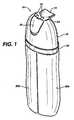
- FIG. 1is a perspective view of an embodiment of the invention which illustrates the cap and containers;
- FIG. 2is a perspective an embodiment of the invention which illustrates the cap and the containers and which shows the shroud cover for the dispenser nozzles an open and ready to dispense position;
- FIG. 3is a perspective view of an embodiment of the invention with the cap and containers drawn in broken line form to show the dispensing valve assembly;
- FIG. 3 a of the dispensing valve assemblyexploded for clarity
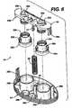
- FIG. 4is a perspective view of an embodiment of the invention showing the dispensing valve assembly with the dispensing button exploded for clarity;
- FIG. 5is an exploded perspective view of an embodiment of a dispensing valve assembly of the invention (the upper assembly, gasket/valve/diaphragm, lower mounting plate);
- FIG. 6is an exploded perspective view of an embodiment of an upper assembly of the invention.
- FIG. 7is a cross-sectional view of an embodiment of the invention showing the upstroke
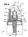
- FIG. 8is a cross-sectional view of the dispensing valve assembly of an embodiment of the invention taken along the plane between two bottles 20 a and 20 b showing the upstroke of the cylindrical valve cylinders;
- FIG. 8 ais a cross-sectional view of an embodiment of the invention taken between two bottles 20 a and 20 b showing the downstroke of the cylindrical valve cylinders;
- FIG. 1depicts an illustrative form of the dosing pump 10 of the present invention, whereby a shroud 12 of an embodiment of the dosing pump 10 is connected to, for example, two bottles 20 a and 20 b.
- a shroud 12 of an embodiment of the dosing pump 10Extending out from the top of shroud 12 is button tab 14 that is generally pressed in a direction to force material out of the dosing pump 10 .
- Dispensing exit nozzle cover 16is connected by hinges 18 to roof 19 of shroud 12 to cover exit holes (not shown) thereby preventing damage to material (not shown) that has not been discharged for use.
- Shroud skirt 22is connected via ribs (not shown) to bottles 20 a and 20 b and shroud 12 to keep the shroud 12 and bottles 20 a and 20 b connected.
- FIG. 2depicts dispensing pump 10 of the invention having exit nozzle cover 16 in the open position.
- exit nozzle cover 16is in the open and ready to dispense material position, thereby exposing two material exit nozzles, 24 a and 24 b that are positioned under nozzle cover 16 .
- Nozzle cover 16comprises two exit plugs 26 a and 26 b that plug material exit nozzles 24 a and 24 b when nozzle cover 16 is closed in a position that forms a portion of the contour of shroud 12 .
- FIG. 3 and FIG. 3 aillustrates the dispensing pump 10 of the present invention.
- Dip tubes 28 a and 28 bextend from inlet valve means (not shown in this view) into bottles 20 a and 20 b, respectively.
- Suction from the inlet valve meansduring the upstroke of the pistons 30 a and 30 b to a piston rest position, draws material 20 c and 20 d from bottles 20 a and 20 b through the inlet valve means into piston cylinders 29 a and 29 b, respectively.
- Tie bar 34mechanically engages tie bar guides 36 a and 36 b through tie bar ribs 34 a and 34 b.
- Tie bar slots, 38 a and 38 bare disposed within tie bar, 34 , and above piston tops, 40 a and 40 b.
- Tie bar post, 31extends downwardly from tie bar, 34 .
- Tie bar guide well, 44extends upwardly from top plate, 54 .
- Top plate, 54is mechanically or moldably or adhesively engaged with gasket, 52 , and through fasteners, 56 .
- Gasket, 52is, in turn, mechanically or adhesively connected to bottom plate, 50 .
- Exit posts, 48 a and 48 bshown in broken line form, extend upwardly from outlet valve ports, 46 a and 46 b respectively.
- FIG. 4is an exploded view of the top portion of an embodiment of pump 10 of the invention.
- FIG. 4shows in more detail, a button tab, 14 , and button legs, 16 a and 16 b.
- button slots, 15 a and 15 bwhich, when the pump 10 is in operation, rest on tie bar slots, 38 a and 38 b respectively.
- the button assemblypivots on tie bar slots, 38 a and 38 b, which cause bottom bars 35 a and 35 b, to mechanically depress tie bar 34 which in turn moves piston tops, 40 a and 40 b, and pistons 30 a and 30 b, to cause dispensing of product from piston chambers, 29 a and 29 b.
- the tie bar and the piston topscan be considered to be actuators as described above.
- FIG. 5is shown an exploded, perspective view of components of pump, 10 , which is an embodiment of the invention, these components being: bottom plate, 50 , gasket, 52 , and top plate, 54 .
- Bottom plate, 50has six fastening tabs, 56 , which secure bottom plate, 50 , to gasket, 52 , and top plate, 54 . It will be understood that more or less than six such fasteners can be used, and that a fastener can be moved to the proximity of exit flaps, 76 a and 76 b, to prevent product leakage.
- Bottom plate, 50has ridges in crescent shapes, 60 a and 60 b; ridges in elongated oval shapes, 62 a and 62 b; and wells, 64 a and 64 b, in association therewith and in communication with circular ridges, 66 a and 66 b, and inner circular ridges, 68 a and 68 b.
- Gasket, 52has two inlet flap valves, 74 a and 74 b, and two exit flap valves, 76 a and 76 b.
- Six square shaped openings 77are for fastening tabs 56 .
- Circular opening, 78is for placement of tie bar guide well 44 .
- FIG. 6is an exploded view of the pumping assembly of pump, 10 , an embodiment of the present invention.
- pistons 30 a and 30 bcomprise respectively piston flanges 35 a and 35 b which are sealably and slidably positioned or mounted within piston cylinders 29 a and 29 b respectively when the components are assembled.
- Piston tops 40 a and 40 brespectively are mechanically engaged with piston bodies 36 a and 36 b respectively.
- FIG. 7shows pump 10 , an embodiment of the invention, during the upward stroke of said pump, when pistons 30 a and 30 b move upwardly under pressure from spring 80 (this will typically happen following a downstroke by the consumer.
- the downstrokeis described below.
- inlet flaps valves, 74 a and 74 bare drawn upward, away from bottom plate, 50 , by suction caused by the upward movement of products 20 c and 20 d, causing flow communication between dip tubes, 28 a and 28 b, and the contents of bottles, 20 a and 20 b; (not shown) thereby drawing said contents upwardly into piston cylinders or chambers 29 a and 29 b.
- FIG. 8shows that during the upward stroke, exit valves flaps, 76 a and exit valve flap 76 b, (not shown) are drawn downward against crescent shaped ridge 60 a and crescent shaped ridge 60 b, (not shown) in bottom plate, 50 , thereby cutting off flow communication between exit post, 48 a and exit post 48 b, (not shown) and piston cylinder, 29 a and piston cylinder 29 b (not shown).
- FIG. 8 ashows an embodiment of the invention, namely, pump 10 , in a downward stroke.
- the contents within piston cylinders, 29 a and piston cylinder 29 b (not shown)are being forced out by mechanical pressure from piston, 30 a and piston 30 b (not shown).
- the pressure of the contentsforces exit flap valve, 76 a and exit valve flap 76 b (not shown), up and away from crescent ridges or beads 60 a and crescent ridges 60 b (not shown), and bottom plate, 50 , and thereby opens flow communication between piston chambers or cylinders, 29 a and 29 b (not shown, and exit posts, 48 a and 48 b (not shown).
- a dosing pump of the inventionmay be used in order to dispense the following two compositions in a simultaneous or nearly simultaneous fashion, with each composition being placed in a different bottle.
- These two compositionsare components in a hair coloring and conditioning composition that is designed to be dispensed by the consumer simultaneously and then mixed and applied to the hair.
- compositionsmay be made by conventional means.
Landscapes
- Containers And Packaging Bodies Having A Special Means To Remove Contents (AREA)
- Coating Apparatus (AREA)
Abstract
Description
| Dark Brown Color conditioner: Part A | |||
| DI Water | 70.00 | ||
| Stearamidopropyl dimethylamine | 0.50 | ||
| Dicetyldimonium chloride/PG, 68%/27% | 2.10 | ||
| Stearyl alcohol and Ceteareth-20, 70% | 1.00 | ||
| Cetyl alcohol | 3.60 | ||
| DI water | 3.00 | ||
| Disodium EDTA | 0.10 | ||
| Dimethicone 100% | 1.00 | ||
| DC silicone fluid 245 | 1.80 | ||
| Kathon CG 1.5% | 0.08 | ||
| DMDM Hydantoin 55% | 0.10 | ||
| Fragrance | 0.20 | ||
| Sodium metabisulfite | 0.10 | ||
| DI water | 15.11 | ||
| m-Aminophenol | 0.03 | ||
| Rodol Grey HED | 0.13 | ||
| p-Phenylenediamine | 0.45 | ||
| o-Aminophenol | 0.05 | ||
| Resorcinol | 0.25 | ||
| 0.40 | |||
| PH = 8 to 9 | |||
| Dark Brown Color conditioner: Part B | |||
| DI Water | 74.00 | ||
| Liquid Citric acid, 50% | 0.20 | ||
| Stearamidopropyl dimethylamine | 0.50 | ||
| Dicetyldimonium chloride/PG, 68%/27% | 2.10 | ||
| Stearyl alcohol and Ceteareth-20, 70% | 1.00 | ||
| Cetyl alcohol | 3.80 | ||
| DI water | 5.00 | ||
| Disodium EDTA | 0.10 | ||
| Dimethicone 100% | 1.00 | ||
| DC silicone fluid 245 | 1.80 | ||
| Hydrogen Peroxide(35%) | 10.00 | ||
| DMDM Hydantoin 55% | 0.10 | ||
| Fragrance | 0.20 | ||
| Phisphoric acid, 85% | 0.09 | ||
| PH = 3.0 | |||
Claims (15)
Priority Applications (14)
| Application Number | Priority Date | Filing Date | Title |
|---|---|---|---|
| US10/054,511US6640999B2 (en) | 2001-11-13 | 2001-11-13 | Dose dispensing pump for dispensing two or more materials |
| US10/135,950US6729501B2 (en) | 2001-11-13 | 2002-07-25 | Dose dispensing pump for dispensing two or more materials |
| EP02802991AEP1444052B1 (en) | 2001-11-13 | 2002-11-05 | Dose dispensing pump for dispensing two or more materials |
| KR1020047007153AKR100917072B1 (en) | 2001-11-13 | 2002-11-05 | Pharmaceutical dispensing pump for dispensing two or more substances |
| CNB028221869ACN1286574C (en) | 2001-11-13 | 2002-11-05 | Metered dispensing pump and dispensing method for dispensing two or more materials and valve mechanism therefor |
| JP2003543746AJP4194945B2 (en) | 2001-11-13 | 2002-11-05 | Dose dispensing pump for dispensing two or more materials |
| ES02802991TES2297051T3 (en) | 2001-11-13 | 2002-11-05 | DOSAGE DISPENSING PUMP FOR DISPENSING TWO OR MORE MATERIALS. |
| MXPA04004411AMXPA04004411A (en) | 2001-11-13 | 2002-11-05 | Dose dispensing pump for dispensing two or more materials. |
| DE60224556TDE60224556T2 (en) | 2001-11-13 | 2002-11-05 | PUMP FOR DISPENSING DOSED QUANTITIES OF TWO OR MORE SUBSTANCES |
| PCT/EP2002/012379WO2003041870A1 (en) | 2001-11-13 | 2002-11-05 | Dose dispensing pump for dispensing two or more materials |
| AT02802991TATE383203T1 (en) | 2001-11-13 | 2002-11-05 | PUMP FOR DISPENSING DOSED QUANTITIES OF TWO OR MORE SUBSTANCES |
| BRPI0214194-9ABR0214194B1 (en) | 2001-11-13 | 2002-11-05 | metering pump and valve assembly for a metering pump. |
| ARP020104347AAR037523A1 (en) | 2001-11-13 | 2002-11-13 | ONE DOSING PUMP TO DISPENSE TWO OR MORE LIQUIDS |
| ZA2004/01540AZA200401540B (en) | 2001-11-13 | 2004-02-25 | Dose dispensing pump for dispensing two or more materials |
Applications Claiming Priority (1)
| Application Number | Priority Date | Filing Date | Title |
|---|---|---|---|
| US10/054,511US6640999B2 (en) | 2001-11-13 | 2001-11-13 | Dose dispensing pump for dispensing two or more materials |
Related Child Applications (1)
| Application Number | Title | Priority Date | Filing Date |
|---|---|---|---|
| US10/135,950Continuation-In-PartUS6729501B2 (en) | 2001-11-13 | 2002-07-25 | Dose dispensing pump for dispensing two or more materials |
Publications (2)
| Publication Number | Publication Date |
|---|---|
| US20030089738A1 US20030089738A1 (en) | 2003-05-15 |
| US6640999B2true US6640999B2 (en) | 2003-11-04 |
Family
ID=21991595
Family Applications (2)
| Application Number | Title | Priority Date | Filing Date |
|---|---|---|---|
| US10/054,511Expired - LifetimeUS6640999B2 (en) | 2001-11-13 | 2001-11-13 | Dose dispensing pump for dispensing two or more materials |
| US10/135,950Expired - LifetimeUS6729501B2 (en) | 2001-11-13 | 2002-07-25 | Dose dispensing pump for dispensing two or more materials |
Family Applications After (1)
| Application Number | Title | Priority Date | Filing Date |
|---|---|---|---|
| US10/135,950Expired - LifetimeUS6729501B2 (en) | 2001-11-13 | 2002-07-25 | Dose dispensing pump for dispensing two or more materials |
Country Status (13)
| Country | Link |
|---|---|
| US (2) | US6640999B2 (en) |
| EP (1) | EP1444052B1 (en) |
| JP (1) | JP4194945B2 (en) |
| KR (1) | KR100917072B1 (en) |
| CN (1) | CN1286574C (en) |
| AR (1) | AR037523A1 (en) |
| AT (1) | ATE383203T1 (en) |
| BR (1) | BR0214194B1 (en) |
| DE (1) | DE60224556T2 (en) |
| ES (1) | ES2297051T3 (en) |
| MX (1) | MXPA04004411A (en) |
| WO (1) | WO2003041870A1 (en) |
| ZA (1) | ZA200401540B (en) |
Cited By (89)
| Publication number | Priority date | Publication date | Assignee | Title |
|---|---|---|---|---|
| US20030146242A1 (en)* | 2001-11-13 | 2003-08-07 | Unilever Home & Personal Care Usa, Division Of Conopco, Inc. | Dose dispensing pump for dispensing two or more materials |
| US20050139613A1 (en)* | 2003-12-24 | 2005-06-30 | Expac Corporation | Fluid dispenser assembly |
| US20060086759A1 (en)* | 2004-10-22 | 2006-04-27 | Herzog Kenneth J | Dispenser assembly |
| US20060163282A1 (en)* | 2003-10-03 | 2006-07-27 | Kao Corporation | Dispensing device |
| USD534813S1 (en) | 2003-12-24 | 2007-01-09 | Expac Corporation | Dual chamber fluid dispenser |
| US20070278174A1 (en)* | 2004-03-11 | 2007-12-06 | Alpla-Werke Alwin Lehner Gmbh & Co. Kg | Security Rotating Closure For A Multi-Compartment Bottle, In Particular For A Dual-Compartment Bottle |
| US20080146977A1 (en)* | 2006-12-19 | 2008-06-19 | Crystal Clear International Limited | Serum Dispensing and Massage Device |
| US20090277912A1 (en)* | 2008-05-12 | 2009-11-12 | Ming Yuan Wang | Dual Tube Container with One Way Valves, and Method for Making Dual Tube Container with Applicator |
| US20090308890A1 (en)* | 2006-09-22 | 2009-12-17 | Nectar Inc | Fluid dispenser |
| US7775401B2 (en) | 2007-06-25 | 2010-08-17 | S.C. Johnson & Son, Inc. | Fluid delivery system for dispensing primary and secondary fluids |
| US20100209870A1 (en)* | 2006-07-07 | 2010-08-19 | Water Pik, Inc. | Oral irrigator |
| US20100239998A1 (en)* | 2009-03-20 | 2010-09-23 | Water Pik, Inc. | Oral irrigator appliance with radiant energy delivery for bactericidal effect |
| US20100266980A1 (en)* | 2006-02-24 | 2010-10-21 | Water Pik. Inc. | Adjustable flow regulator for dental water jet |
| US8113832B2 (en)* | 2002-12-31 | 2012-02-14 | Water Pik, Inc. | Hand held oral irrigator |
| US20120241475A1 (en)* | 2011-03-24 | 2012-09-27 | Dennis Stephen R | Multi-Chamber Trigger Sprayer |
| USD670373S1 (en) | 2010-12-16 | 2012-11-06 | Water Pik, Inc. | Powered irrigator for sinus cavity rinse |
| US20120280065A1 (en)* | 2011-03-24 | 2012-11-08 | Foster Donald D | Multi-chamber trigger sprayer |
| US8668401B2 (en) | 2010-04-05 | 2014-03-11 | Frank Francavilla | Mascara dispensing device |
| USD707350S1 (en) | 2012-10-11 | 2014-06-17 | Water Pik, Inc. | Handheld water flosser |
| US8801667B2 (en) | 2009-12-16 | 2014-08-12 | Water Pik, Inc. | Pump for powered irrigator for sinus cavity rinse |
| USD714929S1 (en) | 2013-03-14 | 2014-10-07 | Water Pik, Inc. | Base for water flosser |
| USD714930S1 (en) | 2013-03-14 | 2014-10-07 | Water Pik, Inc. | Reservoir for water flosser |
| USD717427S1 (en) | 2013-03-14 | 2014-11-11 | Water Pik, Inc. | Handle for water flosser |
| USD725770S1 (en) | 2013-03-14 | 2015-03-31 | Water Pik, Inc. | Reservoir for water flosser |
| USD730077S1 (en) | 2013-11-20 | 2015-05-26 | Nse Products, Inc. | Fluid dispenser |
| USD731204S1 (en) | 2013-11-20 | 2015-06-09 | Nse Products, Inc. | Fluid cartridge |
| USD731203S1 (en) | 2013-11-20 | 2015-06-09 | Nse Products, Inc. | Fluid cartridge |
| USD733455S1 (en) | 2013-11-20 | 2015-07-07 | Nse Products, Inc. | Fluid cartridge assembly |
| USD756122S1 (en) | 2009-01-28 | 2016-05-17 | Water Pik, Inc. | Oral irrigator tip |
| US20160272368A1 (en)* | 2015-03-20 | 2016-09-22 | VariBlend Dual Dispensing Systems LLC | Bottle interlock |
| USD772396S1 (en) | 2014-12-01 | 2016-11-22 | Water Pik, Inc. | Handheld oral irrigator |
| USD772397S1 (en) | 2014-12-01 | 2016-11-22 | Water Pik, Inc. | Oral irrigator with a charging device |
| USD780908S1 (en) | 2015-11-03 | 2017-03-07 | Water Pik, Inc. | Handheld oral irrigator |
| USD782657S1 (en) | 2016-03-02 | 2017-03-28 | Water Pik, Inc. | Oral irrigator handle |
| USD782656S1 (en) | 2016-01-25 | 2017-03-28 | Water Pik, Inc. | Oral irrigator |
| USD783810S1 (en) | 2016-02-22 | 2017-04-11 | Water Pik, Inc. | Handle for an oral irrigator |
| USD783809S1 (en) | 2016-01-25 | 2017-04-11 | Water Pik, Inc. | Oral irrigator handle |
| USD786422S1 (en) | 2016-01-25 | 2017-05-09 | Water Pik, Inc. | Oral irrigator |
| USD788907S1 (en) | 2013-03-14 | 2017-06-06 | Water Pik, Inc. | Water flosser base unit with reservoir lid |
| USD794773S1 (en) | 2016-07-19 | 2017-08-15 | Water Pik, Inc. | Oral irrigator |
| USD796028S1 (en) | 2016-07-19 | 2017-08-29 | Water Pik, Inc. | Oral irrigator |
| USD802120S1 (en) | 2007-02-27 | 2017-11-07 | Water Pik, Inc. | Tip for oral irrigator |
| USD802119S1 (en) | 2016-03-02 | 2017-11-07 | Water Pik, Inc. | Oral irrigator |
| USD802747S1 (en) | 2016-07-19 | 2017-11-14 | Water Pik, Inc. | Reservoir for oral irrigator |
| USD804018S1 (en) | 2016-07-19 | 2017-11-28 | Water Pik, Inc. | Base for an oral irrigator |
| USD804016S1 (en) | 2016-02-05 | 2017-11-28 | Water Pik, Inc. | Handheld oral irrigator |
| USD807822S1 (en) | 2016-07-19 | 2018-01-16 | Water Pik, Inc. | Power supply cartridge |
| USD809650S1 (en) | 2016-02-22 | 2018-02-06 | Water Pik, Inc. | Oral irrigator |
| USD809651S1 (en) | 2016-07-19 | 2018-02-06 | Water Pik, Inc. | Combination base and reservoir for an oral irrigator |
| US9980793B2 (en) | 2013-11-27 | 2018-05-29 | Water Pik, Inc. | Oral hygiene system |
| USD819956S1 (en) | 2016-01-25 | 2018-06-12 | Water Pik, Inc. | Kit bag |
| USD822196S1 (en) | 2016-01-14 | 2018-07-03 | Water Pik, Inc. | Oral irrigator |
| US10016254B2 (en) | 2013-12-20 | 2018-07-10 | Water Pik, Inc. | Dental water jet |
| USD822826S1 (en) | 2016-12-15 | 2018-07-10 | Water Pik, Inc. | Oral irrigator base |
| USD822825S1 (en) | 2016-12-15 | 2018-07-10 | Water Pik, Inc. | Oral irrigator unit |
| US10022741B2 (en) | 2014-08-22 | 2018-07-17 | Nse Products, Inc. | Selectively actuated fluid dispenser |
| US10022207B2 (en) | 2013-11-27 | 2018-07-17 | Water Pik, Inc. | Oral irrigator with slide pause switch |
| USD825741S1 (en) | 2016-12-15 | 2018-08-14 | Water Pik, Inc. | Oral irrigator handle |
| USD829887S1 (en) | 2017-02-06 | 2018-10-02 | Water Pik, Inc. | Oral irrigator reservoir |
| USD829886S1 (en) | 2016-12-15 | 2018-10-02 | Water Pik, Inc. | Oral irrigator base |
| US10105201B2 (en) | 2012-10-11 | 2018-10-23 | Water Pik, Inc. | Interdental cleaner using water supply |
| USD832419S1 (en) | 2016-12-15 | 2018-10-30 | Water Pik, Inc. | Oral irrigator unit |
| USD832418S1 (en) | 2016-12-15 | 2018-10-30 | Water Pik, Inc. | Oral irrigator base |
| USD832420S1 (en) | 2016-12-15 | 2018-10-30 | Water Pik, Inc. | Oral irrigator base |
| USD833000S1 (en) | 2016-12-15 | 2018-11-06 | Water Pik, Inc. | Oral irrigator unit |
| USD833600S1 (en) | 2016-12-15 | 2018-11-13 | Water Pik, Inc. | Oral irrigator reservoir |
| USD833601S1 (en) | 2017-02-06 | 2018-11-13 | Water Pik, Inc. | Oral irrigator |
| USD833602S1 (en) | 2017-02-06 | 2018-11-13 | Water Pik, Inc. | Oral irrigator base |
| USD834180S1 (en) | 2016-12-15 | 2018-11-20 | Water Pik, Inc. | Oral irrigator base |
| USD839409S1 (en) | 2016-12-15 | 2019-01-29 | Water Pik, Inc. | Oral irrigator unit |
| USD840022S1 (en) | 2016-12-15 | 2019-02-05 | Water Pik, Inc. | Oral irrigator handle |
| USD840023S1 (en) | 2016-12-15 | 2019-02-05 | Water Pik, Inc. | Oral irrigator reservoir |
| US10258442B2 (en) | 2009-03-20 | 2019-04-16 | Water Pik, Inc. | Oral irrigator appliance with radiant energy delivery for bactericidal effect |
| USD867579S1 (en) | 2016-12-15 | 2019-11-19 | Water Pik, Inc. | Oral irrigator unit |
| USD868243S1 (en) | 2018-03-16 | 2019-11-26 | Water Pik, Inc. | Oral irrigator tip |
| USD877324S1 (en) | 2018-05-17 | 2020-03-03 | Water Pik, Inc. | Oral irrigator handle |
| USD888936S1 (en) | 2019-02-22 | 2020-06-30 | Water Pik, Inc. | Cordless water flosser |
| USD889636S1 (en) | 2019-02-22 | 2020-07-07 | Water Pik, Inc. | Water flosser |
| US10779922B2 (en) | 2016-12-15 | 2020-09-22 | Water Pik, Inc. | Pause valve and swivel assemblies for oral irrigator handle |
| US10835356B2 (en) | 2016-01-25 | 2020-11-17 | Water Pik, Inc. | Swivel assembly for oral irrigator handle |
| US10993867B2 (en) | 2016-03-02 | 2021-05-04 | Water Pik, Inc. | Actuation assembly for an oral irrigator |
| US11135609B2 (en) | 2017-12-28 | 2021-10-05 | Marene Corona | Multi-nozzle multi-container fluid spray device |
| US11213376B2 (en) | 2016-01-25 | 2022-01-04 | Water Pik, Inc. | Reduced form factor oral irrigator |
| US11389279B2 (en) | 2016-12-15 | 2022-07-19 | Water Pik, Inc. | Oral irrigator with magnetic attachment |
| USD966498S1 (en) | 2020-09-15 | 2022-10-11 | Water Pik, Inc. | Oral irrigator |
| US11826214B2 (en) | 2014-12-01 | 2023-11-28 | Water Pik, Inc. | Oral irrigator |
| USD1016274S1 (en) | 2021-02-16 | 2024-02-27 | Water Pik, Inc. | Oral irrigator |
| US20240174402A1 (en)* | 2021-08-04 | 2024-05-30 | Matan Pinto | Dual bottle |
| US20250089624A1 (en)* | 2023-09-20 | 2025-03-20 | II Richard P. Steinke | Dual compartment container |
Families Citing this family (47)
| Publication number | Priority date | Publication date | Assignee | Title |
|---|---|---|---|---|
| DE10322354A1 (en)* | 2003-04-11 | 2004-10-28 | Hilti Corporation | Hand-held dispenser pump for pasty or highly viscous adhesive has pump chamber with flexible walls which allow reduction in volume and telescopic two-part housing |
| MXPA05011721A (en)* | 2003-05-01 | 2006-01-23 | Procter & Gamble | Visually distinctive multiple liquid phase compositions. |
| HRP20030802A2 (en)* | 2003-10-03 | 2005-04-30 | Vrus-Pervan Iris | Precise hair colouring implement to form frosted and streaky hair and the method for protecting uncoloured hair |
| US20050121025A1 (en)* | 2003-12-04 | 2005-06-09 | Gamard Stephan C.F. | Portable gas operating inhaler |
| ITMI20030588U1 (en)* | 2003-12-12 | 2005-06-13 | Reggiani Fulvio | CONTAINER FOR THE DISTRIBUTION OF DISTINCT PRODUCTS |
| US7367476B2 (en) | 2004-08-30 | 2008-05-06 | Rieke Corporation | Airless dispensing pump with tamper evidence features |
| US7654418B2 (en)* | 2004-08-30 | 2010-02-02 | Rieke Corporation | Airless dispensing pump |
| KR101231945B1 (en) | 2004-11-23 | 2013-02-08 | 엔테그리스, 아이엔씨. | System and method for a variable home position dispense system |
| USD543865S1 (en) | 2005-09-20 | 2007-06-05 | Walters Peter J | Dual dispenser package with dual actuators |
| USD543864S1 (en) | 2005-09-20 | 2007-06-05 | Cho Sean H | Dual dispenser package with single actuator |
| US7651012B2 (en)* | 2005-09-30 | 2010-01-26 | The Procter & Gamble Company | Toothpaste dispenser, toothpaste dispensing system and kit |
| WO2007061956A2 (en)* | 2005-11-21 | 2007-05-31 | Entegris, Inc. | System and method for a pump with reduced form factor |
| US8753097B2 (en) | 2005-11-21 | 2014-06-17 | Entegris, Inc. | Method and system for high viscosity pump |
| US7878765B2 (en) | 2005-12-02 | 2011-02-01 | Entegris, Inc. | System and method for monitoring operation of a pump |
| US8083498B2 (en) | 2005-12-02 | 2011-12-27 | Entegris, Inc. | System and method for position control of a mechanical piston in a pump |
| US8029247B2 (en) | 2005-12-02 | 2011-10-04 | Entegris, Inc. | System and method for pressure compensation in a pump |
| ITMI20060151A1 (en)* | 2006-01-30 | 2007-07-31 | Microspray Delta Spa | PUMP PUSH BUTTON WITH ITS MOBILE DRIVE OF A PORTION COMPARED TO A PORTION WITH A NOZZLE OR DELIVERY TABLET AND ELEMENTS FOR ITS RETURN PUMP |
| TWI402423B (en)* | 2006-02-28 | 2013-07-21 | Entegris Inc | System and method for operation of a pump |
| DE202007004405U1 (en)* | 2006-04-21 | 2007-08-30 | Megaplast Gmbh & Co. Kg | Dispenser for dispensing liquid to pasty masses |
| ES2351255T3 (en)* | 2006-06-14 | 2011-02-02 | Rexam Dispensing Smt | MULTIPLE PUMP DISTRIBUTOR. |
| GB0715224D0 (en)* | 2007-08-02 | 2007-09-12 | Leafgreen Ltd | Manual pump type fluid dispenser and a method of manufacturing such a dispenser |
| GB0719827D0 (en)* | 2007-10-11 | 2007-11-21 | Unilever Plc | Refill bottle for appliance dispensing heated cosmetic fluids |
| WO2010003091A1 (en)* | 2008-07-03 | 2010-01-07 | Meadwestvaco Calmar, Inc. | Variable volume pump |
| KR101037361B1 (en)* | 2009-03-10 | 2011-05-26 | (주)연우 | Cosmetic container that mixes different contents |
| USD679001S1 (en)* | 2011-06-15 | 2013-03-26 | Nigel Kelly | Micro dispensing pump |
| DE202012004644U1 (en)* | 2012-05-11 | 2013-05-13 | Gerhard Brugger | Spray dispenser for several components |
| WO2014077842A1 (en)* | 2012-11-19 | 2014-05-22 | Colgate-Palmolive Company | Multi-chamber container |
| KR200476949Y1 (en)* | 2013-08-22 | 2015-04-20 | 펌텍코리아 (주) | A cosmetic container for sotoraging and discharging two contents |
| US9452440B2 (en)* | 2014-05-21 | 2016-09-27 | Triumph Pharmaceuticals Inc. | Multi-chambered bottle with metering stage, pour spout and cap |
| KR101501027B1 (en)* | 2014-06-16 | 2015-03-12 | (주)연우 | Pump vessel for dispensing of capsule |
| DE102014216744B4 (en)* | 2014-08-22 | 2016-03-03 | Aptar Radolfzell Gmbh | Discharge head for a dosing dispenser and dosing dispenser |
| USD766738S1 (en)* | 2015-03-16 | 2016-09-20 | Roy Lane Buckner, III | Dual dispenser bottle |
| EP3162449B1 (en)* | 2015-10-28 | 2018-05-23 | Aptar Radolfzell GmbH | Discharge head and dispenser with such a discharge head |
| USD805401S1 (en)* | 2016-12-03 | 2017-12-19 | Daniel Boctor | Two compartment squeeze bottle |
| KR101910428B1 (en)* | 2017-01-23 | 2018-10-22 | (주)연우 | Vessel for Dispensing different kind of fluid |
| KR20210008861A (en) | 2018-06-29 | 2021-01-25 | 더 프록터 앤드 갬블 캄파니 | Dual phase product |
| WO2020006327A1 (en) | 2018-06-29 | 2020-01-02 | The Procter & Gamble Company | Dual phase products |
| KR20210008853A (en)* | 2018-06-29 | 2021-01-25 | 더 프록터 앤드 갬블 캄파니 | Dual phase product distributor |
| WO2020005787A2 (en) | 2018-06-29 | 2020-01-02 | The Procter & Gamble Company | Dual phase products |
| JP7319401B2 (en) | 2019-07-09 | 2023-08-01 | ザ プロクター アンド ギャンブル カンパニー | Multi-composition product dispenser |
| EP3996851B1 (en) | 2019-07-09 | 2024-08-07 | The Procter & Gamble Company | Multi-composition product dispenser |
| KR102299386B1 (en)* | 2019-08-26 | 2021-09-09 | 애경산업(주) | Pump dispenser for dual vessel |
| US11226224B2 (en)* | 2019-12-27 | 2022-01-18 | L'oreal | Dual dispensing pack |
| IT202000002281A1 (en)* | 2020-02-05 | 2020-05-05 | Hero Europe S R L | Device for dispensing and dosing powder or pasty or liquid materials |
| CN114615911A (en) | 2020-10-05 | 2022-06-10 | 阿波罗工业株式会社 | Cosmetic container assembly capable of simultaneously discharging multiple contents |
| EP4320054A4 (en)* | 2021-04-06 | 2024-12-11 | L'oreal | DEVICE FOR STORING AND DISPENSING AT LEAST TWO COSMETIC PRODUCTS AND ASSOCIATED METHOD |
| WO2025020122A1 (en)* | 2023-07-26 | 2025-01-30 | Henkel Ag & Co. Kgaa | Mixer for fluid components |
Citations (12)
| Publication number | Priority date | Publication date | Assignee | Title |
|---|---|---|---|---|
| US4273268A (en) | 1977-12-13 | 1981-06-16 | Seaquist Valve Co., Div. Of Pittway | Fluid spray pump |
| US4396132A (en) | 1981-08-14 | 1983-08-02 | Christensen Kurt K | Apparatus and process for removing and dispensing liquid from a receptacle |
| EP0318834A1 (en) | 1987-12-04 | 1989-06-07 | Henkel Kommanditgesellschaft auf Aktien | Device for dispensing at least two liquids |
| US4949874A (en) | 1987-12-04 | 1990-08-21 | Henkel Kommanditgesellschaft Auf Aktien | Device for dispensing at least two flowable substances |
| US5224627A (en)* | 1991-06-22 | 1993-07-06 | Firma Raimund Andris Gmbh & Co., Kg. | Metering pump dispenser for liquid and/or pasty media |
| US5310112A (en)* | 1992-03-05 | 1994-05-10 | Philip Meshberg | Valved gasket for dispenser |
| US5398846A (en) | 1993-08-20 | 1995-03-21 | S. C. Johnson & Son, Inc. | Assembly for simultaneous dispensing of multiple fluids |
| US5405057A (en) | 1993-10-21 | 1995-04-11 | Moore; David G. | Manually actuated pump |
| US5617976A (en)* | 1995-03-21 | 1997-04-08 | L'oreal | Dispenser of liquid or pasty product which can be used especially in cosmetics |
| US5673824A (en) | 1995-05-31 | 1997-10-07 | Taplast Srl | Plastic dosing pump for dispensing liquids from containers |
| EP0953381A2 (en) | 1998-04-30 | 1999-11-03 | Calmar-Monturas, S.A. | Fluid pump dispenser |
| US6082588A (en)* | 1997-01-10 | 2000-07-04 | Lever Brothers Company, Division Of Conopco, Inc. | Dual compartment package and pumps |
Family Cites Families (3)
| Publication number | Priority date | Publication date | Assignee | Title |
|---|---|---|---|---|
| US5025829A (en)* | 1990-01-29 | 1991-06-25 | Harmac Medical Products, Inc. | Parenteral check valve |
| US6161729A (en)* | 1998-12-14 | 2000-12-19 | Unilever Home & Personal Care Usa, Division Of Conopco | Dual chamber dispenser |
| US6640999B2 (en)* | 2001-11-13 | 2003-11-04 | Unilever Home & Personal Care Usa, Division Of Conopco, Inc. | Dose dispensing pump for dispensing two or more materials |
- 2001
- 2001-11-13USUS10/054,511patent/US6640999B2/ennot_activeExpired - Lifetime
- 2002
- 2002-07-25USUS10/135,950patent/US6729501B2/ennot_activeExpired - Lifetime
- 2002-11-05WOPCT/EP2002/012379patent/WO2003041870A1/enactiveIP Right Grant
- 2002-11-05JPJP2003543746Apatent/JP4194945B2/ennot_activeExpired - Fee Related
- 2002-11-05EPEP02802991Apatent/EP1444052B1/ennot_activeExpired - Lifetime
- 2002-11-05ESES02802991Tpatent/ES2297051T3/ennot_activeExpired - Lifetime
- 2002-11-05DEDE60224556Tpatent/DE60224556T2/ennot_activeExpired - Lifetime
- 2002-11-05KRKR1020047007153Apatent/KR100917072B1/ennot_activeExpired - Fee Related
- 2002-11-05MXMXPA04004411Apatent/MXPA04004411A/enactiveIP Right Grant
- 2002-11-05CNCNB028221869Apatent/CN1286574C/ennot_activeExpired - Fee Related
- 2002-11-05ATAT02802991Tpatent/ATE383203T1/ennot_activeIP Right Cessation
- 2002-11-05BRBRPI0214194-9Apatent/BR0214194B1/ennot_activeIP Right Cessation
- 2002-11-13ARARP020104347Apatent/AR037523A1/ennot_activeApplication Discontinuation
- 2004
- 2004-02-25ZAZA2004/01540Apatent/ZA200401540B/enunknown
Patent Citations (12)
| Publication number | Priority date | Publication date | Assignee | Title |
|---|---|---|---|---|
| US4273268A (en) | 1977-12-13 | 1981-06-16 | Seaquist Valve Co., Div. Of Pittway | Fluid spray pump |
| US4396132A (en) | 1981-08-14 | 1983-08-02 | Christensen Kurt K | Apparatus and process for removing and dispensing liquid from a receptacle |
| EP0318834A1 (en) | 1987-12-04 | 1989-06-07 | Henkel Kommanditgesellschaft auf Aktien | Device for dispensing at least two liquids |
| US4949874A (en) | 1987-12-04 | 1990-08-21 | Henkel Kommanditgesellschaft Auf Aktien | Device for dispensing at least two flowable substances |
| US5224627A (en)* | 1991-06-22 | 1993-07-06 | Firma Raimund Andris Gmbh & Co., Kg. | Metering pump dispenser for liquid and/or pasty media |
| US5310112A (en)* | 1992-03-05 | 1994-05-10 | Philip Meshberg | Valved gasket for dispenser |
| US5398846A (en) | 1993-08-20 | 1995-03-21 | S. C. Johnson & Son, Inc. | Assembly for simultaneous dispensing of multiple fluids |
| US5405057A (en) | 1993-10-21 | 1995-04-11 | Moore; David G. | Manually actuated pump |
| US5617976A (en)* | 1995-03-21 | 1997-04-08 | L'oreal | Dispenser of liquid or pasty product which can be used especially in cosmetics |
| US5673824A (en) | 1995-05-31 | 1997-10-07 | Taplast Srl | Plastic dosing pump for dispensing liquids from containers |
| US6082588A (en)* | 1997-01-10 | 2000-07-04 | Lever Brothers Company, Division Of Conopco, Inc. | Dual compartment package and pumps |
| EP0953381A2 (en) | 1998-04-30 | 1999-11-03 | Calmar-Monturas, S.A. | Fluid pump dispenser |
Non-Patent Citations (1)
| Title |
|---|
| International Search Report. |
Cited By (157)
| Publication number | Priority date | Publication date | Assignee | Title |
|---|---|---|---|---|
| US20030146242A1 (en)* | 2001-11-13 | 2003-08-07 | Unilever Home & Personal Care Usa, Division Of Conopco, Inc. | Dose dispensing pump for dispensing two or more materials |
| US6729501B2 (en)* | 2001-11-13 | 2004-05-04 | Unilever Home & Personal Care Usa, Division Of Conopco, Inc. | Dose dispensing pump for dispensing two or more materials |
| US10617500B2 (en) | 2002-12-31 | 2020-04-14 | Water Pik, Inc. | Oral irrigator |
| US9980794B2 (en) | 2002-12-31 | 2018-05-29 | Water Pik, Inc. | Irrigating device with variable pressure pulse |
| US8113832B2 (en)* | 2002-12-31 | 2012-02-14 | Water Pik, Inc. | Hand held oral irrigator |
| US20120141952A1 (en)* | 2002-12-31 | 2012-06-07 | Water Pik, Inc. | Irrigating device with reed valve |
| US20060163282A1 (en)* | 2003-10-03 | 2006-07-27 | Kao Corporation | Dispensing device |
| US7824124B2 (en) | 2003-12-24 | 2010-11-02 | Lucas Publications, Inc. | Fluid dispenser assembly |
| US20050139613A1 (en)* | 2003-12-24 | 2005-06-30 | Expac Corporation | Fluid dispenser assembly |
| US7467908B2 (en) | 2003-12-24 | 2008-12-23 | Lucas Publications, Inc. | Fluid dispenser assembly |
| US20090010703A1 (en)* | 2003-12-24 | 2009-01-08 | Lucas Packaging Group, Inc. | Fluid dispenser assembly |
| US20090032134A1 (en)* | 2003-12-24 | 2009-02-05 | Lucas Publications, Inc. | Fluid dispenser assembly |
| US8226319B2 (en) | 2003-12-24 | 2012-07-24 | Lucas Publications, Inc. | Fluid dispenser assembly |
| USD534813S1 (en) | 2003-12-24 | 2007-01-09 | Expac Corporation | Dual chamber fluid dispenser |
| US20110027005A1 (en)* | 2003-12-24 | 2011-02-03 | Lucas Publications, Inc. | Fluid dispenser assembly |
| US20070278174A1 (en)* | 2004-03-11 | 2007-12-06 | Alpla-Werke Alwin Lehner Gmbh & Co. Kg | Security Rotating Closure For A Multi-Compartment Bottle, In Particular For A Dual-Compartment Bottle |
| US8123057B2 (en)* | 2004-03-11 | 2012-02-28 | Alpha-Werke Alwin Lehner GmbH & Co KG | Security rotating closure for a multi-compartment bottle including conical seals |
| US20060086759A1 (en)* | 2004-10-22 | 2006-04-27 | Herzog Kenneth J | Dispenser assembly |
| US10010389B2 (en) | 2006-02-24 | 2018-07-03 | Water Pik, Inc. | Dental water jet device |
| US11432916B2 (en) | 2006-02-24 | 2022-09-06 | Water Pik, Inc. | Oral irrigator with handle support |
| US9050157B2 (en) | 2006-02-24 | 2015-06-09 | Water Pik, Inc. | Dental water jet with storage container reservoir cover |
| US8888727B2 (en) | 2006-02-24 | 2014-11-18 | Water Pik, Inc. | Vibration damping for dental water jet |
| US11872097B2 (en) | 2006-02-24 | 2024-01-16 | Water Pik, Inc. | Dental water jet with storage container reservoir cover |
| US8641649B2 (en) | 2006-02-24 | 2014-02-04 | Water Pik, Inc. | Pump for dental water jet |
| US11197745B2 (en) | 2006-02-24 | 2021-12-14 | Water Pik, Inc. | Removable fluid connection fitting for oral irrigator |
| US8408483B2 (en) | 2006-02-24 | 2013-04-02 | Water Pik, Inc. | Adjustable flow regulator for dental water jet |
| US20100266980A1 (en)* | 2006-02-24 | 2010-10-21 | Water Pik. Inc. | Adjustable flow regulator for dental water jet |
| US8808209B2 (en) | 2006-02-24 | 2014-08-19 | Water Pik, Inc. | Dental water jet irrigator handle |
| US20100209870A1 (en)* | 2006-07-07 | 2010-08-19 | Water Pik, Inc. | Oral irrigator |
| US9775692B2 (en) | 2006-07-07 | 2017-10-03 | Water Pik, Inc. | Oral irrigator with variable pressure |
| USD747464S1 (en) | 2006-07-07 | 2016-01-12 | Water Pik, Inc. | Handheld oral irrigator |
| US8403665B2 (en) | 2006-07-07 | 2013-03-26 | Water Pik, Inc. | Oral irrigator |
| US20090308890A1 (en)* | 2006-09-22 | 2009-12-17 | Nectar Inc | Fluid dispenser |
| US8302817B2 (en)* | 2006-09-22 | 2012-11-06 | Darren Saravis | Fluid dispenser |
| US20080161737A1 (en)* | 2006-12-19 | 2008-07-03 | Crystal Clear International Limited | Serum Dispensing and Massage Device |
| US20080146977A1 (en)* | 2006-12-19 | 2008-06-19 | Crystal Clear International Limited | Serum Dispensing and Massage Device |
| USD867580S1 (en) | 2007-02-27 | 2019-11-19 | Water Pik, Inc. | Oral irrigator tip with bristles |
| USD802120S1 (en) | 2007-02-27 | 2017-11-07 | Water Pik, Inc. | Tip for oral irrigator |
| US20100206903A1 (en)* | 2007-06-25 | 2010-08-19 | Banco Michael J | Fluid delivery system for dispensing primary and secondary fluids |
| US7997449B2 (en) | 2007-06-25 | 2011-08-16 | S.C. Johnson & Son, Inc. | Fluid delivery system for dispensing primary and secondary fluids |
| US7775401B2 (en) | 2007-06-25 | 2010-08-17 | S.C. Johnson & Son, Inc. | Fluid delivery system for dispensing primary and secondary fluids |
| US20090277912A1 (en)* | 2008-05-12 | 2009-11-12 | Ming Yuan Wang | Dual Tube Container with One Way Valves, and Method for Making Dual Tube Container with Applicator |
| US8052016B2 (en)* | 2008-12-05 | 2011-11-08 | Udn Packaging Corp. | Dual tube container with one way valves and applicator |
| USD756122S1 (en) | 2009-01-28 | 2016-05-17 | Water Pik, Inc. | Oral irrigator tip |
| US11173020B2 (en) | 2009-03-20 | 2021-11-16 | Water Pik, Inc. | Oral irrigator appliance with radiant energy delivery for bactericidal effect |
| US20100239998A1 (en)* | 2009-03-20 | 2010-09-23 | Water Pik, Inc. | Oral irrigator appliance with radiant energy delivery for bactericidal effect |
| US10258442B2 (en) | 2009-03-20 | 2019-04-16 | Water Pik, Inc. | Oral irrigator appliance with radiant energy delivery for bactericidal effect |
| US9061096B2 (en) | 2009-12-16 | 2015-06-23 | Water Pik, Inc. | Powered irrigator for sinus cavity rinse |
| US8808245B2 (en) | 2009-12-16 | 2014-08-19 | Water Pik, Inc. | Powered irrigator for sinus cavity rinse with detachable reservoir |
| US8801667B2 (en) | 2009-12-16 | 2014-08-12 | Water Pik, Inc. | Pump for powered irrigator for sinus cavity rinse |
| US8668401B2 (en) | 2010-04-05 | 2014-03-11 | Frank Francavilla | Mascara dispensing device |
| USD694398S1 (en) | 2010-12-16 | 2013-11-26 | Water Pik, Inc. | Powered irrigator for sinus cavity rinse |
| USD670373S1 (en) | 2010-12-16 | 2012-11-06 | Water Pik, Inc. | Powered irrigator for sinus cavity rinse |
| US20120241475A1 (en)* | 2011-03-24 | 2012-09-27 | Dennis Stephen R | Multi-Chamber Trigger Sprayer |
| US20120280065A1 (en)* | 2011-03-24 | 2012-11-08 | Foster Donald D | Multi-chamber trigger sprayer |
| USD707350S1 (en) | 2012-10-11 | 2014-06-17 | Water Pik, Inc. | Handheld water flosser |
| US10105201B2 (en) | 2012-10-11 | 2018-10-23 | Water Pik, Inc. | Interdental cleaner using water supply |
| USD731640S1 (en) | 2013-03-14 | 2015-06-09 | Water Pik, Inc. | Reservoir for a water flosser |
| USD714929S1 (en) | 2013-03-14 | 2014-10-07 | Water Pik, Inc. | Base for water flosser |
| USD754330S1 (en) | 2013-03-14 | 2016-04-19 | Water Pik, Inc. | Handle for a water flosser |
| US10945912B2 (en) | 2013-03-14 | 2021-03-16 | Water Pik, Inc. | Oral irrigator with variable output fluid characteristics |
| US9597161B2 (en) | 2013-03-14 | 2017-03-21 | Water Pik, Inc. | Oral irrigator with integrated lid and base |
| USD725770S1 (en) | 2013-03-14 | 2015-03-31 | Water Pik, Inc. | Reservoir for water flosser |
| USD718855S1 (en) | 2013-03-14 | 2014-12-02 | Water Pik, Inc. | Base for water flosser |
| USD714930S1 (en) | 2013-03-14 | 2014-10-07 | Water Pik, Inc. | Reservoir for water flosser |
| USD798440S1 (en) | 2013-03-14 | 2017-09-26 | Water Pik, Inc. | Water flosser base unit |
| US9642677B2 (en) | 2013-03-14 | 2017-05-09 | Water Pik, Inc. | Oral irrigator with massage mode |
| USD740936S1 (en) | 2013-03-14 | 2015-10-13 | Water Pik, Inc. | Water flosser base unit |
| USD788907S1 (en) | 2013-03-14 | 2017-06-06 | Water Pik, Inc. | Water flosser base unit with reservoir lid |
| USD717427S1 (en) | 2013-03-14 | 2014-11-11 | Water Pik, Inc. | Handle for water flosser |
| USD733455S1 (en) | 2013-11-20 | 2015-07-07 | Nse Products, Inc. | Fluid cartridge assembly |
| USD730077S1 (en) | 2013-11-20 | 2015-05-26 | Nse Products, Inc. | Fluid dispenser |
| USD731204S1 (en) | 2013-11-20 | 2015-06-09 | Nse Products, Inc. | Fluid cartridge |
| USD731203S1 (en) | 2013-11-20 | 2015-06-09 | Nse Products, Inc. | Fluid cartridge |
| US11039906B2 (en) | 2013-11-27 | 2021-06-22 | Water Pik, Inc. | Tip ejection assembly for an oral irrigator |
| US10022207B2 (en) | 2013-11-27 | 2018-07-17 | Water Pik, Inc. | Oral irrigator with slide pause switch |
| US9980793B2 (en) | 2013-11-27 | 2018-05-29 | Water Pik, Inc. | Oral hygiene system |
| US10016254B2 (en) | 2013-12-20 | 2018-07-10 | Water Pik, Inc. | Dental water jet |
| US10022741B2 (en) | 2014-08-22 | 2018-07-17 | Nse Products, Inc. | Selectively actuated fluid dispenser |
| US12383387B2 (en) | 2014-12-01 | 2025-08-12 | Water Pik, Inc. | Oral irrigator |
| USD819196S1 (en) | 2014-12-01 | 2018-05-29 | Water Pik, Inc. | Handheld oral irrigator |
| USD772396S1 (en) | 2014-12-01 | 2016-11-22 | Water Pik, Inc. | Handheld oral irrigator |
| US11826214B2 (en) | 2014-12-01 | 2023-11-28 | Water Pik, Inc. | Oral irrigator |
| USD772397S1 (en) | 2014-12-01 | 2016-11-22 | Water Pik, Inc. | Oral irrigator with a charging device |
| US20160272368A1 (en)* | 2015-03-20 | 2016-09-22 | VariBlend Dual Dispensing Systems LLC | Bottle interlock |
| USD780908S1 (en) | 2015-11-03 | 2017-03-07 | Water Pik, Inc. | Handheld oral irrigator |
| USD873025S1 (en) | 2016-01-14 | 2020-01-21 | Water Pik, Inc. | Toothbrush handle |
| USD880688S1 (en) | 2016-01-14 | 2020-04-07 | Water Pik, Inc. | Oral irrigator handle |
| USD822196S1 (en) | 2016-01-14 | 2018-07-03 | Water Pik, Inc. | Oral irrigator |
| USD907763S1 (en) | 2016-01-14 | 2021-01-12 | Water Pik, Inc. | Oral irrigator |
| USD783809S1 (en) | 2016-01-25 | 2017-04-11 | Water Pik, Inc. | Oral irrigator handle |
| US12207983B2 (en) | 2016-01-25 | 2025-01-28 | Water Pik, Inc. | Oral irrigator handle with hose connector fittings |
| USD782656S1 (en) | 2016-01-25 | 2017-03-28 | Water Pik, Inc. | Oral irrigator |
| US11213376B2 (en) | 2016-01-25 | 2022-01-04 | Water Pik, Inc. | Reduced form factor oral irrigator |
| USD786422S1 (en) | 2016-01-25 | 2017-05-09 | Water Pik, Inc. | Oral irrigator |
| US10835356B2 (en) | 2016-01-25 | 2020-11-17 | Water Pik, Inc. | Swivel assembly for oral irrigator handle |
| US12186147B2 (en) | 2016-01-25 | 2025-01-07 | Water Pik, Inc. | Reduced form factor oral irrigator |
| USD819956S1 (en) | 2016-01-25 | 2018-06-12 | Water Pik, Inc. | Kit bag |
| US11642203B2 (en) | 2016-01-25 | 2023-05-09 | Water Pik, Inc. | Oral irrigator handle with hose connector fittings |
| USD804016S1 (en) | 2016-02-05 | 2017-11-28 | Water Pik, Inc. | Handheld oral irrigator |
| USD815274S1 (en) | 2016-02-05 | 2018-04-10 | Water Pik, Inc. | Handheld oral irrigator |
| USD809650S1 (en) | 2016-02-22 | 2018-02-06 | Water Pik, Inc. | Oral irrigator |
| USD839410S1 (en) | 2016-02-22 | 2019-01-29 | Water Pik, Inc. | Oral irrigator |
| USD873409S1 (en) | 2016-02-22 | 2020-01-21 | Water Pik, Inc. | Oral irrigator |
| USD783810S1 (en) | 2016-02-22 | 2017-04-11 | Water Pik, Inc. | Handle for an oral irrigator |
| USD802119S1 (en) | 2016-03-02 | 2017-11-07 | Water Pik, Inc. | Oral irrigator |
| USD782657S1 (en) | 2016-03-02 | 2017-03-28 | Water Pik, Inc. | Oral irrigator handle |
| US11607359B2 (en) | 2016-03-02 | 2023-03-21 | Water Pik, Inc. | Actuation assembly for an oral irrigator |
| US10993867B2 (en) | 2016-03-02 | 2021-05-04 | Water Pik, Inc. | Actuation assembly for an oral irrigator |
| USD794773S1 (en) | 2016-07-19 | 2017-08-15 | Water Pik, Inc. | Oral irrigator |
| USD796028S1 (en) | 2016-07-19 | 2017-08-29 | Water Pik, Inc. | Oral irrigator |
| USD802747S1 (en) | 2016-07-19 | 2017-11-14 | Water Pik, Inc. | Reservoir for oral irrigator |
| USD804018S1 (en) | 2016-07-19 | 2017-11-28 | Water Pik, Inc. | Base for an oral irrigator |
| USD807822S1 (en) | 2016-07-19 | 2018-01-16 | Water Pik, Inc. | Power supply cartridge |
| USD809651S1 (en) | 2016-07-19 | 2018-02-06 | Water Pik, Inc. | Combination base and reservoir for an oral irrigator |
| US11389279B2 (en) | 2016-12-15 | 2022-07-19 | Water Pik, Inc. | Oral irrigator with magnetic attachment |
| USD840023S1 (en) | 2016-12-15 | 2019-02-05 | Water Pik, Inc. | Oral irrigator reservoir |
| USD867579S1 (en) | 2016-12-15 | 2019-11-19 | Water Pik, Inc. | Oral irrigator unit |
| USD832418S1 (en) | 2016-12-15 | 2018-10-30 | Water Pik, Inc. | Oral irrigator base |
| USD832419S1 (en) | 2016-12-15 | 2018-10-30 | Water Pik, Inc. | Oral irrigator unit |
| USD834180S1 (en) | 2016-12-15 | 2018-11-20 | Water Pik, Inc. | Oral irrigator base |
| USD839409S1 (en) | 2016-12-15 | 2019-01-29 | Water Pik, Inc. | Oral irrigator unit |
| USD840022S1 (en) | 2016-12-15 | 2019-02-05 | Water Pik, Inc. | Oral irrigator handle |
| USD893017S1 (en) | 2016-12-15 | 2020-08-11 | Water Pik, Inc. | Oral irrigator unit |
| US10779922B2 (en) | 2016-12-15 | 2020-09-22 | Water Pik, Inc. | Pause valve and swivel assemblies for oral irrigator handle |
| USD829886S1 (en) | 2016-12-15 | 2018-10-02 | Water Pik, Inc. | Oral irrigator base |
| USD832420S1 (en) | 2016-12-15 | 2018-10-30 | Water Pik, Inc. | Oral irrigator base |
| USD870268S1 (en) | 2016-12-15 | 2019-12-17 | Water Pik, Inc. | Oral irrigator handle |
| USD833600S1 (en) | 2016-12-15 | 2018-11-13 | Water Pik, Inc. | Oral irrigator reservoir |
| USD833000S1 (en) | 2016-12-15 | 2018-11-06 | Water Pik, Inc. | Oral irrigator unit |
| USD825741S1 (en) | 2016-12-15 | 2018-08-14 | Water Pik, Inc. | Oral irrigator handle |
| USD872855S1 (en) | 2016-12-15 | 2020-01-14 | Water Pik, Inc. | Oral irrigator unit |
| USD822825S1 (en) | 2016-12-15 | 2018-07-10 | Water Pik, Inc. | Oral irrigator unit |
| USD822826S1 (en) | 2016-12-15 | 2018-07-10 | Water Pik, Inc. | Oral irrigator base |
| USD829887S1 (en) | 2017-02-06 | 2018-10-02 | Water Pik, Inc. | Oral irrigator reservoir |
| USD833601S1 (en) | 2017-02-06 | 2018-11-13 | Water Pik, Inc. | Oral irrigator |
| USD833602S1 (en) | 2017-02-06 | 2018-11-13 | Water Pik, Inc. | Oral irrigator base |
| US11135609B2 (en) | 2017-12-28 | 2021-10-05 | Marene Corona | Multi-nozzle multi-container fluid spray device |
| USD868243S1 (en) | 2018-03-16 | 2019-11-26 | Water Pik, Inc. | Oral irrigator tip |
| USD890917S1 (en) | 2018-03-16 | 2020-07-21 | Water Pik, Inc. | Oral irrigator tip |
| USD975843S1 (en) | 2018-05-17 | 2023-01-17 | Water Pik, Inc. | Oral irrigator handle |
| USD950710S1 (en) | 2018-05-17 | 2022-05-03 | Water Pik, Inc. | Oral irrigator handle |
| USD877324S1 (en) | 2018-05-17 | 2020-03-03 | Water Pik, Inc. | Oral irrigator handle |
| USD912241S1 (en) | 2019-02-22 | 2021-03-02 | Water Pik, Inc. | Water flosser |
| USD889636S1 (en) | 2019-02-22 | 2020-07-07 | Water Pik, Inc. | Water flosser |
| USD980414S1 (en) | 2019-02-22 | 2023-03-07 | Water Pik, Inc. | Reservoir for water flosser |
| USD913486S1 (en) | 2019-02-22 | 2021-03-16 | Water Pik, Inc. | Cordless water flosser |
| USD956957S1 (en) | 2019-02-22 | 2022-07-05 | Water Pik, Inc. | Reservoir for water flosser |
| USD992728S1 (en) | 2019-02-22 | 2023-07-18 | Water Pik, Inc. | Base for water flosser |
| USD902385S1 (en) | 2019-02-22 | 2020-11-17 | Water Pik, Inc. | Cordless water flosser |
| USD945601S1 (en) | 2019-02-22 | 2022-03-08 | Water Pik, Inc. | Cordless water flosser |
| USD888936S1 (en) | 2019-02-22 | 2020-06-30 | Water Pik, Inc. | Cordless water flosser |
| USD969994S1 (en) | 2019-02-22 | 2022-11-15 | Water Pik, Inc. | Cordless water flosser |
| USD966498S1 (en) | 2020-09-15 | 2022-10-11 | Water Pik, Inc. | Oral irrigator |
| USD1016274S1 (en) | 2021-02-16 | 2024-02-27 | Water Pik, Inc. | Oral irrigator |
| US20240174402A1 (en)* | 2021-08-04 | 2024-05-30 | Matan Pinto | Dual bottle |
| US20250089624A1 (en)* | 2023-09-20 | 2025-03-20 | II Richard P. Steinke | Dual compartment container |
Also Published As
| Publication number | Publication date |
|---|---|
| AR037523A1 (en) | 2004-11-17 |
| WO2003041870A1 (en) | 2003-05-22 |
| US6729501B2 (en) | 2004-05-04 |
| ATE383203T1 (en) | 2008-01-15 |
| CN1286574C (en) | 2006-11-29 |
| KR20040062629A (en) | 2004-07-07 |
| EP1444052A1 (en) | 2004-08-11 |
| DE60224556D1 (en) | 2008-02-21 |
| MXPA04004411A (en) | 2004-08-11 |
| JP4194945B2 (en) | 2008-12-10 |
| ZA200401540B (en) | 2005-05-25 |
| EP1444052B1 (en) | 2008-01-09 |
| BR0214194B1 (en) | 2011-09-20 |
| KR100917072B1 (en) | 2009-09-15 |
| US20030146242A1 (en) | 2003-08-07 |
| JP2005508742A (en) | 2005-04-07 |
| BR0214194A (en) | 2004-08-31 |
| CN1582203A (en) | 2005-02-16 |
| ES2297051T3 (en) | 2008-05-01 |
| DE60224556T2 (en) | 2009-01-22 |
| US20030089738A1 (en) | 2003-05-15 |
Similar Documents
| Publication | Publication Date | Title |
|---|---|---|
| US6640999B2 (en) | Dose dispensing pump for dispensing two or more materials | |
| EP0953381B1 (en) | Fluid pump dispenser | |
| KR101236315B1 (en) | Dispenser with airtight spout | |
| US7850048B2 (en) | Foamer pump | |
| US8591207B2 (en) | Pump with side inlet valve for improved functioning in an inverted container | |
| JP4210215B2 (en) | Dosing device with medium reservoir and pump device therefor | |
| US20010025863A1 (en) | Dispensing pump, dispenser and dispenser unit-assembly | |
| RU2759648C2 (en) | Product dosing device with improved launch | |
| US7775404B2 (en) | Pump for dispensing fluid products | |
| KR100381537B1 (en) | Fluid pump dispenser | |
| DE2428977A1 (en) | DISPENSING PUMP FOR MOUNTING ON A CONTAINER | |
| CN100402158C (en) | distribution device | |
| CA2234193A1 (en) | Upright/inverted sprayer | |
| HK1092438B (en) | Dispenser having air tight spout |
Legal Events
| Date | Code | Title | Description |
|---|---|---|---|
| AS | Assignment | Owner name:UNILEVER HOME & PERSONAL CARE USA, DIVISION OF CON Free format text:ASSIGNMENT OF ASSIGNORS INTEREST;ASSIGNOR:PETERSON, ERIK;REEL/FRAME:012724/0972 Effective date:20011211 | |
| STCF | Information on status: patent grant | Free format text:PATENTED CASE | |
| FEPP | Fee payment procedure | Free format text:PAYOR NUMBER ASSIGNED (ORIGINAL EVENT CODE: ASPN); ENTITY STATUS OF PATENT OWNER: LARGE ENTITY | |
| FPAY | Fee payment | Year of fee payment:4 | |
| AS | Assignment | Owner name:DS&S CHASE, LLC, VIRGINIA Free format text:SECURITY INTEREST;ASSIGNOR:ZOUNDS HEARING, INC.;REEL/FRAME:025780/0205 Effective date:20101220 Owner name:DERWOOD S. CHASE, JR., THE, GRAND TRUST, VIRGINIA Free format text:SECURITY INTEREST;ASSIGNOR:ZOUNDS HEARING, INC.;REEL/FRAME:025780/0205 Effective date:20101220 Owner name:STUART F. CHASE, THE, 2001 IRREVOCABLE TRUST, VIRG Free format text:SECURITY INTEREST;ASSIGNOR:ZOUNDS HEARING, INC.;REEL/FRAME:025780/0205 Effective date:20101220 Owner name:D. SUMNER CHASE, III, THE, 2001 IRREVOCABLE TRUST, Free format text:SECURITY INTEREST;ASSIGNOR:ZOUNDS HEARING, INC.;REEL/FRAME:025780/0205 Effective date:20101220 | |
| FPAY | Fee payment | Year of fee payment:8 | |
| FPAY | Fee payment | Year of fee payment:12 |