US6640895B2 - Expandable tubing joint and through-tubing multilateral completion method - Google Patents
Expandable tubing joint and through-tubing multilateral completion methodDownload PDFInfo
- Publication number
- US6640895B2 US6640895B2US09/898,794US89879401AUS6640895B2US 6640895 B2US6640895 B2US 6640895B2US 89879401 AUS89879401 AUS 89879401AUS 6640895 B2US6640895 B2US 6640895B2
- Authority
- US
- United States
- Prior art keywords
- tubing
- extension
- tubing string
- wellbore
- string
- Prior art date
- Legal status (The legal status is an assumption and is not a legal conclusion. Google has not performed a legal analysis and makes no representation as to the accuracy of the status listed.)
- Expired - Lifetime, expires
Links
Images


Classifications
- E—FIXED CONSTRUCTIONS
- E21—EARTH OR ROCK DRILLING; MINING
- E21B—EARTH OR ROCK DRILLING; OBTAINING OIL, GAS, WATER, SOLUBLE OR MELTABLE MATERIALS OR A SLURRY OF MINERALS FROM WELLS
- E21B41/00—Equipment or details not covered by groups E21B15/00 - E21B40/00
- E21B41/0035—Apparatus or methods for multilateral well technology, e.g. for the completion of or workover on wells with one or more lateral branches
- E—FIXED CONSTRUCTIONS
- E21—EARTH OR ROCK DRILLING; MINING
- E21B—EARTH OR ROCK DRILLING; OBTAINING OIL, GAS, WATER, SOLUBLE OR MELTABLE MATERIALS OR A SLURRY OF MINERALS FROM WELLS
- E21B33/00—Sealing or packing boreholes or wells
- E21B33/10—Sealing or packing boreholes or wells in the borehole
- E21B33/13—Methods or devices for cementing, for plugging holes, crevices or the like
- E21B33/14—Methods or devices for cementing, for plugging holes, crevices or the like for cementing casings into boreholes
- E—FIXED CONSTRUCTIONS
- E21—EARTH OR ROCK DRILLING; MINING
- E21B—EARTH OR ROCK DRILLING; OBTAINING OIL, GAS, WATER, SOLUBLE OR MELTABLE MATERIALS OR A SLURRY OF MINERALS FROM WELLS
- E21B43/00—Methods or apparatus for obtaining oil, gas, water, soluble or meltable materials or a slurry of minerals from wells
- E21B43/02—Subsoil filtering
- E21B43/10—Setting of casings, screens, liners or the like in wells
- E21B43/103—Setting of casings, screens, liners or the like in wells of expandable casings, screens, liners, or the like
Definitions
- a multilateral junction from an existing wellboreis desirable however, cost often proves to be a limiting factor in the incorporation of multilateral junctions into the existing wellbores.
- Conventional wellborestypically comprise a casing of either steel or concrete and a tubing string concentrically positioned therein, through which oil and gas are removed from subsurface reservoirs.
- the incorporation of a multilateral junction into an existing wellboreinvolves the removal of the tubing string within the wellbore to allow full bore access to the interior surface of the casing to create exit windows in the casing for lateral drilling operations.
- Such removal of the tubing stringis an expensive and laborious undertaking.
- the tools to be used to create the multilateral junctionmust be run through the smaller ID tubing and then must be used in the larger ID casing. In such an instance, the centralization of tools and the ability to retrieve the tools through the narrower tubing become issues.
- a through-tubing multilateral system and method for installing the same for downhole oil drilling operationsincludes a tubing extension positioned in a downhole end of a tubing string in a wellbore and anchored in place.
- the tubing extensionis dimensioned to obtain the most minimal tubing restriction possible such that it facilitates the installation of a multilateral junction therethrough.
- the tubing extension of the through-tubing multilateral systemincludes a main body portion and thin walled section.
- the thin walled sectionis attached to an uphole edge of the body portion.
- the thickness of the wall of the thin walled sectionis less than the thickness of the wall of the body portion in order to allow for a lesser reduction in the ID of the string at the juncture between the original tubing string and the extension tubing.
- the tubing extensionoverall has an outside diameter less than an inside diameter of the tubing string (and any restrictions in the original tubing string) and is installed in direct contact with an inner surface of the downhole end of the tubing string.
- the juncture between the thin walled section and the tubing stringis swaged to smooth the intersection between the original tubing string and the extension string.
- the extension tubing stringis anchorable by cementing the annulus or installing an inflatable or collapsible packer or similar device.
- One advantage of this system and processis that only one set of equipment is needed for a particular size of tubing string.
- the tools used for each particular size of tubing stringare, therefore, independent of the bore diameter defined by the interior surface of the casing.
- Another advantage of the systemis its ability to enable the multilateral junction to be installed from within the tubing string rather than in the wider area of the casing below the tubing string.
- the systemoffers considerable savings over removing the tubing string from the wellbore and installing a multilateral junction in a conventional manner, especially in remote locations.
- FIG. 1is a side sectional view of a wellbore in which a tubing string is concentrically disposed within a casing, and wherein the casing extends beyond a terminus of the tubing string.
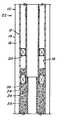
- FIG. 2is a side sectional view of a wellbore in which the tubing string is concentrically disposed within the casing, and wherein the tubing string is extended and anchored within the wellbore.
- FIG. 3is a side sectional view of a tubing extension showing a main body portion of a greater wall thickness and a thin walled section.
- FIG. 4is an alternate embodiment wherein the tubing extension is expanded in its entirety.
- a through-tubing multilateral system for an existing oil well where a multilateral junction is desired at a location below the downhole end of an installed tubing stringis disclosed.
- the systeminvolves extending the downhole end of the tubing string in the casing of the bore to install a multilateral junction through the extended tubing string wall from the inside of the tubing string by creating an exit window through the tubing string, traversing the annulus between the tubing string and the casing, and through the casing wall. Lateral drilling can then be performed and a new completion extended into a gas and/or oil formation.
- a conventional wellboreis shown generally at 10 and is hereinafter referred to as “bore 10 ”.
- Bore 10comprises a tubing string, shown generally at 12 , concentrically supported within a casing 14 to form an annulus 16 therebetween.
- a completed wellboreincludes either 51 ⁇ 2 inch diameter tubing inside a 95 ⁇ 8 inch diameter casing or 41 ⁇ 2 inch diameter tubing inside a 7 inch diameter casing.
- Tubing string 12is supported within casing 14 by a packer 20 .
- each of a plurality of packers 20is inserted into annulus 16 at various places along the length of bore 10 . Inflation or expansion of packer 20 holds tubing string 12 relatively concentrically positioned within casing 14 and takes up any clearance between liner 18 and the outer surface of tubing string 12 .
- Various types of devicesare often positioned within annulus 16 to monitor the flow of gas or oil within tubing string 12 . These devices typically traverse the wall of tubing string 12 and protrude into the space defined by the ID of tubing string 12 . Depending upon the size of the protrusion into tubing string 12 , the flow of gas and oil may be somewhat restricted. These devices typically include flow control nipples (not shown) or safety valve nipples (not shown). Prior to the incorporation of the through-tubing multilateral system, such devices should be removed or milled out from the interior of the tubing to make the cross sectional area of tubing string 12 as large and unrestricted as possible.
- a through-tubing multilateral systemis illustrated generally at 22 and is installed in bore 10 .
- Through-tubing multilateral system 22comprises tubing string 12 concentrically supported in casing 14 , as in FIG. 1 .
- through-tubing multilateral system 22further includes a tubing extension, shown generally at 24 , through which the multilateral junction can be installed without centralizers. It is desirable to anchor the extension with a form of anchoring system which may be by cementing the annulus around the extension, which incidentally also provides for zonal isolation, or may be by expandable or inflatable packers, etc.
- tubing extension 24is run through tubing string 12 such that tubing extension 24 extends beyond a terminus 26 of tubing string 12 but overlaps tubing string 12 slightly at terminus 26 .
- the final depth of tubing of the tubing extension 24should be deeper in bore 10 than the level at which any multilateral junction is likely to be installed. Because tubing extension 24 is run into bore 10 through tubing string 12 , it must have an outside diameter that is smaller than an inside diameter of the tightest restriction in the tubing string 12 . In order to gain the greatest effectiveness of the system it is desirable to expand the entire length of the tubing extension with either an inflatable tool or a swage. Additionally the expansion can be done in a single operation or in a number of smaller sections sequentially.
- tubing extension 24comprises a main body portion 28 having a thin walled section 30 attached thereto and is oriented in the bore such that thin walled section 30 is “uphole” relative to body portion 28 . This is because it is the thin walled section that is intended to be overlapped with the tubing string 12 .
- the thin walled sectionprovides for a smaller restriction at the juncture of tubing string 12 and tubing extension 24 .
- An inner surface of tubing extension 24is configured to be smooth and relatively free of variations in the region at which thin walled section 30 is attached to main body portion 28 .
- An outer surface of tubing extension 24is configured to define a shoulder 32 that extends outward from section 30 to main body portion 28 at the point at which the portion 28 and section 30 are joined.
- Shoulder 32is configured to define main body portion 28 as having a wall thickness 34 that is substantially equal to the wall thickness of the tubing string 12 and thin walled section 30 as having a wall thickness 36 that is somewhat less than wall thickness 34 of main body portion 28 .
- tubing extension 24 on tubing string 12causes an aberration in the transition of the inner surfaces between tubing extension 24 and tubing string 12 .
- the aberrationis typically a raised ridge formed by section 30 of tubing extension 24 protruding concentrically inwardly from the I.D. of tubing string 12 .
- the thin wallis employed to reduce this effect.
- the swaging or expansion operationminimizes this effect farther by expanding the juncture to a diameter significantly enough larger than the size prior to expanding that upon rebound very little restriction is present.
- the inside diameter of tubing extension 24is substantially the same as the minimum restriction in tubing string 12 .
- tubing extension 24is preferably cemented in place with cement 25 before the window and lateral borehole are drilled which acts as a support system.
- Alternative support systemsinclude packers located around the tubing extension and may be at a juncture of the tubing extension and the tubing string.
- Cement 25provides support for the conventional installation of the multilateral junction proximate the point at which tubing string 12 and tubing extension 24 meet.
- the extension tubing stringis anchorable by cementing the annulus or installing an inflatable or collapsible packer or similar device 38 .
- a window in the tubing and the casingis created using standard whipstocks and whipstock anchoring systems (not shown). Multilateral junction can then be installed.
Landscapes
- Life Sciences & Earth Sciences (AREA)
- Engineering & Computer Science (AREA)
- Geology (AREA)
- Mining & Mineral Resources (AREA)
- Physics & Mathematics (AREA)
- Environmental & Geological Engineering (AREA)
- Fluid Mechanics (AREA)
- General Life Sciences & Earth Sciences (AREA)
- Geochemistry & Mineralogy (AREA)
- Earth Drilling (AREA)
- Pipeline Systems (AREA)
- Electric Cable Installation (AREA)
Abstract
Description
This application claims the benefit of an earlier filing date from U.S. Provisional Application Serial No. 60/216,823 filed Jul. 7, 2000, the entire disclosure of which is incorporated herein by reference.
A large number of single vertical bore oil wells exist in mature or maturing oil fields where the use of multilateral junctions in the vertical bores would allow additional reserves of oil or gas to be accessed. In areas where surface locations are limited, for example, in offshore drilling operations or drilling on the North Slope of Alaska, a multilateral junction from an existing wellbore is desirable however, cost often proves to be a limiting factor in the incorporation of multilateral junctions into the existing wellbores.
Conventional wellbores typically comprise a casing of either steel or concrete and a tubing string concentrically positioned therein, through which oil and gas are removed from subsurface reservoirs.
In one prior art application, the incorporation of a multilateral junction into an existing wellbore involves the removal of the tubing string within the wellbore to allow full bore access to the interior surface of the casing to create exit windows in the casing for lateral drilling operations. Such removal of the tubing string is an expensive and laborious undertaking.
In another prior art application, where the multilateral junction is to be installed at a location below the depth of a terminus of the original tubing string, the tools to be used to create the multilateral junction must be run through the smaller ID tubing and then must be used in the larger ID casing. In such an instance, the centralization of tools and the ability to retrieve the tools through the narrower tubing become issues.
A through-tubing multilateral system and method for installing the same for downhole oil drilling operations includes a tubing extension positioned in a downhole end of a tubing string in a wellbore and anchored in place. The tubing extension is dimensioned to obtain the most minimal tubing restriction possible such that it facilitates the installation of a multilateral junction therethrough.
The tubing extension of the through-tubing multilateral system includes a main body portion and thin walled section. The thin walled section is attached to an uphole edge of the body portion. The thickness of the wall of the thin walled section is less than the thickness of the wall of the body portion in order to allow for a lesser reduction in the ID of the string at the juncture between the original tubing string and the extension tubing. The tubing extension overall has an outside diameter less than an inside diameter of the tubing string (and any restrictions in the original tubing string) and is installed in direct contact with an inner surface of the downhole end of the tubing string. The juncture between the thin walled section and the tubing string is swaged to smooth the intersection between the original tubing string and the extension string.
The extension tubing string is anchorable by cementing the annulus or installing an inflatable or collapsible packer or similar device.
One advantage of this system and process is that only one set of equipment is needed for a particular size of tubing string. The tools used for each particular size of tubing string are, therefore, independent of the bore diameter defined by the interior surface of the casing. Another advantage of the system is its ability to enable the multilateral junction to be installed from within the tubing string rather than in the wider area of the casing below the tubing string. In addition to the ease of working within the tubing string as opposed to below the downhole end of the tubing string, the system offers considerable savings over removing the tubing string from the wellbore and installing a multilateral junction in a conventional manner, especially in remote locations.
FIG. 1 is a side sectional view of a wellbore in which a tubing string is concentrically disposed within a casing, and wherein the casing extends beyond a terminus of the tubing string.
FIG. 2 is a side sectional view of a wellbore in which the tubing string is concentrically disposed within the casing, and wherein the tubing string is extended and anchored within the wellbore.
FIG. 3 is a side sectional view of a tubing extension showing a main body portion of a greater wall thickness and a thin walled section.
FIG. 4 is an alternate embodiment wherein the tubing extension is expanded in its entirety.
A through-tubing multilateral system for an existing oil well where a multilateral junction is desired at a location below the downhole end of an installed tubing string is disclosed. The system involves extending the downhole end of the tubing string in the casing of the bore to install a multilateral junction through the extended tubing string wall from the inside of the tubing string by creating an exit window through the tubing string, traversing the annulus between the tubing string and the casing, and through the casing wall. Lateral drilling can then be performed and a new completion extended into a gas and/or oil formation.
Referring to FIG. 1, a conventional wellbore is shown generally at10 and is hereinafter referred to as “bore10”.Bore 10 comprises a tubing string, shown generally at12, concentrically supported within acasing 14 to form anannulus 16 therebetween. Typically, a completed wellbore includes either 5½ inch diameter tubing inside a 9⅝ inch diameter casing or 4½ inch diameter tubing inside a 7 inch diameter casing.Tubing string 12 is supported withincasing 14 by apacker 20. In an uninflated or collapsed state, each of a plurality ofpackers 20 is inserted intoannulus 16 at various places along the length ofbore 10. Inflation or expansion ofpacker 20 holdstubing string 12 relatively concentrically positioned withincasing 14 and takes up any clearance betweenliner 18 and the outer surface oftubing string 12.
Various types of devices are often positioned withinannulus 16 to monitor the flow of gas or oil withintubing string 12. These devices typically traverse the wall oftubing string 12 and protrude into the space defined by the ID oftubing string 12. Depending upon the size of the protrusion intotubing string 12, the flow of gas and oil may be somewhat restricted. These devices typically include flow control nipples (not shown) or safety valve nipples (not shown). Prior to the incorporation of the through-tubing multilateral system, such devices should be removed or milled out from the interior of the tubing to make the cross sectional area oftubing string 12 as large and unrestricted as possible.
Referring now to FIG. 2, a through-tubing multilateral system is illustrated generally at22 and is installed inbore 10. Through-tubingmultilateral system 22 comprisestubing string 12 concentrically supported incasing 14, as in FIG.1. However, through-tubingmultilateral system 22 further includes a tubing extension, shown generally at24, through which the multilateral junction can be installed without centralizers. It is desirable to anchor the extension with a form of anchoring system which may be by cementing the annulus around the extension, which incidentally also provides for zonal isolation, or may be by expandable or inflatable packers, etc. To create a multilateral junction utilizing through-tubingmultilateral system 22,tubing extension 24 is run throughtubing string 12 such thattubing extension 24 extends beyond aterminus 26 oftubing string 12 but overlapstubing string 12 slightly atterminus 26. The final depth of tubing of thetubing extension 24 should be deeper inbore 10 than the level at which any multilateral junction is likely to be installed. Becausetubing extension 24 is run intobore 10 throughtubing string 12, it must have an outside diameter that is smaller than an inside diameter of the tightest restriction in thetubing string 12. In order to gain the greatest effectiveness of the system it is desirable to expand the entire length of the tubing extension with either an inflatable tool or a swage. Additionally the expansion can be done in a single operation or in a number of smaller sections sequentially.
Referring to FIG. 3,tubing extension 24 is shown in greater detail.Tubing extension 24 comprises amain body portion 28 having a thinwalled section 30 attached thereto and is oriented in the bore such that thinwalled section 30 is “uphole” relative tobody portion 28. This is because it is the thin walled section that is intended to be overlapped with thetubing string 12. The thin walled section provides for a smaller restriction at the juncture oftubing string 12 andtubing extension 24. An inner surface oftubing extension 24 is configured to be smooth and relatively free of variations in the region at which thinwalled section 30 is attached tomain body portion 28. An outer surface oftubing extension 24 is configured to define ashoulder 32 that extends outward fromsection 30 tomain body portion 28 at the point at which theportion 28 andsection 30 are joined.Shoulder 32 is configured to definemain body portion 28 as having awall thickness 34 that is substantially equal to the wall thickness of thetubing string 12 and thinwalled section 30 as having awall thickness 36 that is somewhat less thanwall thickness 34 ofmain body portion 28.
Referring to all of the Figures, the overlapping oftubing extension 24 ontubing string 12 causes an aberration in the transition of the inner surfaces betweentubing extension 24 andtubing string 12. The aberration is typically a raised ridge formed bysection 30 oftubing extension 24 protruding concentrically inwardly from the I.D. oftubing string 12. As stated the thin wall is employed to reduce this effect. In addition, the swaging or expansion operation minimizes this effect farther by expanding the juncture to a diameter significantly enough larger than the size prior to expanding that upon rebound very little restriction is present. In a preferred embodiment, the inside diameter oftubing extension 24 is substantially the same as the minimum restriction intubing string 12.
Oncetubing extension 24 is properly positioned withinbore 10,tubing extension 24 is preferably cemented in place withcement 25 before the window and lateral borehole are drilled which acts as a support system. Alternative support systems include packers located around the tubing extension and may be at a juncture of the tubing extension and the tubing string.Cement 25 provides support for the conventional installation of the multilateral junction proximate the point at whichtubing string 12 andtubing extension 24 meet. The extension tubing string is anchorable by cementing the annulus or installing an inflatable or collapsible packer orsimilar device 38. A window in the tubing and the casing is created using standard whipstocks and whipstock anchoring systems (not shown). Multilateral junction can then be installed.
While preferred embodiments have been shown and described, various modifications and substitutions may be made thereto without departing from the spirit and scope of the invention. Accordingly, it is to be understood that the present invention has been described by way of illustration and not limitation.
Claims (17)
1. A through-tubing multilateral system for drilling operations, comprising:
a tubing extension positioned at a downhole end of a tubing string in a wellbore, said tubing extension comprising a main body portion and a thin walled section disposed thereat, said thin walled section being thin prior to installing said extension in a wellbore and being the section overlapping the end of the tubing string; and
an anchoring system configured and positioned to anchor said tubing extension in said wellbore.
2. The through-tubing multilateral system ofclaim 1 wherein said tubing extension has an outside diameter less than an inside diameter of said tubing string.
3. The through-tubing multilateral system ofclaim 1 wherein said thin walled section being positioned at an uphole edge of said body portion.
4. The through-tubing multilateral system ofclaim 3 wherein said thin walled section is configured to have a thinner wall thickness than said body portion.
5. The through-tubing multilateral system ofclaim 4 wherein said thin walled section is in interference fit contact with an inner surface of a downhole end of said tubing string to form a juncture of said thin walled section and said tubing string.
6. The through-tubing multilateral system ofclaim 5 wherein said juncture between said thin walled section and said tubing string is swaged to effectuate a smooth surface between said tubing string and said thin walled section.
7. The through-tubing multilateral system ofclaim 1 wherein said anchoring system is positioned at an overlapping juncture of said tubing extension and said tubing string.
8. The through-tubing multilateral system ofclaim 7 wherein said anchoring system is cement.
9. The through-tubing multilateral system ofclaim 7 wherein said anchoring system is a packer.
10. A tubing extension for downhole oil drilling operations in a wellbore, comprising:
a body portion configured to be tubular in structure; and
a thin walled section attached to an end of said body portion, said thin walled section having a wall thickness that is less than a wall thickness of said body portion prior to being installed in a wellbore and wherein said section is necked down from an outside dimension of the tubing extension.
11. The tubing extension ofclaim 10 wherein said tubing extension is dimensioned to be slidingly received in a tubing string of said wellbore.
12. A method of extending tubing string in a wellbore, comprising:
running a tubing extension into a tubing string in said wellbore such that an uphole end of said tubing extension is overlapped by a downhole end of said tubing string, said extension having a body portion and a lip portion and wherein said lip portion has a thickness less than said body portion prior to being installed in said wellbore and is the section overlapping the end of the tubing string;
expanding said tubing extension such that said tubing extension is secured in position by said tubing string; and
anchoring said tubing extension in said wellbore.
13. The method ofclaim 12 further comprising the milling out of restrictions in said tubing string prior to running in said tubing extension.
14. The method ofclaim 12 wherein said expanding of said tubing extension comprises the swaging of said tubing extension.
15. The method ofclaim 12 wherein said anchoring of said tubing extension in said wellbore comprises cementing a juncture of said tubing extension and said tubing string.
16. The method ofclaim 12 wherein said anchoring of said tubing extension in said wellbore comprises installing a packer around a juncture of said tubing extension and said tubing string.
17. The method ofclaim 12 wherein said tubing extension is expanded along the entire length thereof.
Priority Applications (1)
| Application Number | Priority Date | Filing Date | Title |
|---|---|---|---|
| US09/898,794US6640895B2 (en) | 2000-07-07 | 2001-07-03 | Expandable tubing joint and through-tubing multilateral completion method |
Applications Claiming Priority (2)
| Application Number | Priority Date | Filing Date | Title |
|---|---|---|---|
| US21682300P | 2000-07-07 | 2000-07-07 | |
| US09/898,794US6640895B2 (en) | 2000-07-07 | 2001-07-03 | Expandable tubing joint and through-tubing multilateral completion method |
Publications (2)
| Publication Number | Publication Date |
|---|---|
| US20020011339A1 US20020011339A1 (en) | 2002-01-31 |
| US6640895B2true US6640895B2 (en) | 2003-11-04 |
Family
ID=22808649
Family Applications (1)
| Application Number | Title | Priority Date | Filing Date |
|---|---|---|---|
| US09/898,794Expired - LifetimeUS6640895B2 (en) | 2000-07-07 | 2001-07-03 | Expandable tubing joint and through-tubing multilateral completion method |
Country Status (5)
| Country | Link |
|---|---|
| US (1) | US6640895B2 (en) |
| AU (1) | AU784997B2 (en) |
| CA (1) | CA2352604C (en) |
| GB (1) | GB2365040B (en) |
| NO (1) | NO330425B1 (en) |
Cited By (47)
| Publication number | Priority date | Publication date | Assignee | Title |
|---|---|---|---|---|
| US20020189816A1 (en)* | 1998-12-07 | 2002-12-19 | Shell Oil Co. | Wellbore casing |
| US20040069499A1 (en)* | 2000-10-02 | 2004-04-15 | Cook Robert Lance | Mono-diameter wellbore casing |
| US20050073196A1 (en)* | 2003-09-29 | 2005-04-07 | Yamaha Motor Co. Ltd. | Theft prevention system, theft prevention apparatus and power source controller for the system, transport vehicle including theft prevention system, and theft prevention method |
| US7011161B2 (en) | 1998-12-07 | 2006-03-14 | Shell Oil Company | Structural support |
| US7048067B1 (en) | 1999-11-01 | 2006-05-23 | Shell Oil Company | Wellbore casing repair |
| US7077211B2 (en) | 1998-12-07 | 2006-07-18 | Shell Oil Company | Method of creating a casing in a borehole |
| US7086475B2 (en) | 1998-12-07 | 2006-08-08 | Shell Oil Company | Method of inserting a tubular member into a wellbore |
| US7121352B2 (en) | 1998-11-16 | 2006-10-17 | Enventure Global Technology | Isolation of subterranean zones |
| US7146702B2 (en) | 2000-10-02 | 2006-12-12 | Shell Oil Company | Method and apparatus for forming a mono-diameter wellbore casing |
| US7159667B2 (en) | 1999-02-25 | 2007-01-09 | Shell Oil Company | Method of coupling a tubular member to a preexisting structure |
| US7168496B2 (en) | 2001-07-06 | 2007-01-30 | Eventure Global Technology | Liner hanger |
| US7174964B2 (en) | 1998-12-07 | 2007-02-13 | Shell Oil Company | Wellhead with radially expanded tubulars |
| US7185710B2 (en) | 1998-12-07 | 2007-03-06 | Enventure Global Technology | Mono-diameter wellbore casing |
| US7195064B2 (en) | 1998-12-07 | 2007-03-27 | Enventure Global Technology | Mono-diameter wellbore casing |
| US7231985B2 (en) | 1998-11-16 | 2007-06-19 | Shell Oil Company | Radial expansion of tubular members |
| US7240728B2 (en) | 1998-12-07 | 2007-07-10 | Shell Oil Company | Expandable tubulars with a radial passage and wall portions with different wall thicknesses |
| US7243731B2 (en) | 2001-08-20 | 2007-07-17 | Enventure Global Technology | Apparatus for radially expanding tubular members including a segmented expansion cone |
| US7246667B2 (en) | 1998-11-16 | 2007-07-24 | Shell Oil Company | Radial expansion of tubular members |
| US7258168B2 (en) | 2001-07-27 | 2007-08-21 | Enventure Global Technology L.L.C. | Liner hanger with slip joint sealing members and method of use |
| US7290616B2 (en) | 2001-07-06 | 2007-11-06 | Enventure Global Technology, L.L.C. | Liner hanger |
| US7308755B2 (en) | 2003-06-13 | 2007-12-18 | Shell Oil Company | Apparatus for forming a mono-diameter wellbore casing |
| US7325602B2 (en) | 2000-10-02 | 2008-02-05 | Shell Oil Company | Method and apparatus for forming a mono-diameter wellbore casing |
| US7360591B2 (en) | 2002-05-29 | 2008-04-22 | Enventure Global Technology, Llc | System for radially expanding a tubular member |
| US7363984B2 (en) | 1998-12-07 | 2008-04-29 | Enventure Global Technology, Llc | System for radially expanding a tubular member |
| US7377326B2 (en) | 2002-08-23 | 2008-05-27 | Enventure Global Technology, L.L.C. | Magnetic impulse applied sleeve method of forming a wellbore casing |
| US7383889B2 (en) | 2001-11-12 | 2008-06-10 | Enventure Global Technology, Llc | Mono diameter wellbore casing |
| US7398832B2 (en) | 2002-06-10 | 2008-07-15 | Enventure Global Technology, Llc | Mono-diameter wellbore casing |
| US7404444B2 (en) | 2002-09-20 | 2008-07-29 | Enventure Global Technology | Protective sleeve for expandable tubulars |
| US7410000B2 (en) | 2001-01-17 | 2008-08-12 | Enventure Global Technology, Llc. | Mono-diameter wellbore casing |
| US7416027B2 (en) | 2001-09-07 | 2008-08-26 | Enventure Global Technology, Llc | Adjustable expansion cone assembly |
| US7424918B2 (en) | 2002-08-23 | 2008-09-16 | Enventure Global Technology, L.L.C. | Interposed joint sealing layer method of forming a wellbore casing |
| US7438132B2 (en) | 1999-03-11 | 2008-10-21 | Shell Oil Company | Concentric pipes expanded at the pipe ends and method of forming |
| US7438133B2 (en) | 2003-02-26 | 2008-10-21 | Enventure Global Technology, Llc | Apparatus and method for radially expanding and plastically deforming a tubular member |
| US7503393B2 (en) | 2003-01-27 | 2009-03-17 | Enventure Global Technology, Inc. | Lubrication system for radially expanding tubular members |
| US7513313B2 (en) | 2002-09-20 | 2009-04-07 | Enventure Global Technology, Llc | Bottom plug for forming a mono diameter wellbore casing |
| US7552776B2 (en) | 1998-12-07 | 2009-06-30 | Enventure Global Technology, Llc | Anchor hangers |
| US7571774B2 (en) | 2002-09-20 | 2009-08-11 | Eventure Global Technology | Self-lubricating expansion mandrel for expandable tubular |
| US7603758B2 (en) | 1998-12-07 | 2009-10-20 | Shell Oil Company | Method of coupling a tubular member |
| US7712522B2 (en) | 2003-09-05 | 2010-05-11 | Enventure Global Technology, Llc | Expansion cone and system |
| US20100147592A1 (en)* | 2008-12-11 | 2010-06-17 | Conocophillips Company | Mill-Through Tailpipe Liner Exit |
| US7740076B2 (en) | 2002-04-12 | 2010-06-22 | Enventure Global Technology, L.L.C. | Protective sleeve for threaded connections for expandable liner hanger |
| US7739917B2 (en) | 2002-09-20 | 2010-06-22 | Enventure Global Technology, Llc | Pipe formability evaluation for expandable tubulars |
| US7775290B2 (en) | 2003-04-17 | 2010-08-17 | Enventure Global Technology, Llc | Apparatus for radially expanding and plastically deforming a tubular member |
| US7793721B2 (en) | 2003-03-11 | 2010-09-14 | Eventure Global Technology, Llc | Apparatus for radially expanding and plastically deforming a tubular member |
| US7819185B2 (en) | 2004-08-13 | 2010-10-26 | Enventure Global Technology, Llc | Expandable tubular |
| US7886831B2 (en) | 2003-01-22 | 2011-02-15 | Enventure Global Technology, L.L.C. | Apparatus for radially expanding and plastically deforming a tubular member |
| US7918284B2 (en) | 2002-04-15 | 2011-04-05 | Enventure Global Technology, L.L.C. | Protective sleeve for threaded connections for expandable liner hanger |
Families Citing this family (23)
| Publication number | Priority date | Publication date | Assignee | Title |
|---|---|---|---|---|
| US6745845B2 (en) | 1998-11-16 | 2004-06-08 | Shell Oil Company | Isolation of subterranean zones |
| US6712154B2 (en) | 1998-11-16 | 2004-03-30 | Enventure Global Technology | Isolation of subterranean zones |
| US6634431B2 (en) | 1998-11-16 | 2003-10-21 | Robert Lance Cook | Isolation of subterranean zones |
| US6575240B1 (en) | 1998-12-07 | 2003-06-10 | Shell Oil Company | System and method for driving pipe |
| US20070051520A1 (en)* | 1998-12-07 | 2007-03-08 | Enventure Global Technology, Llc | Expansion system |
| CA2306656C (en)* | 1999-04-26 | 2006-06-06 | Shell Internationale Research Maatschappij B.V. | Expandable connector for borehole tubes |
| US7350563B2 (en)* | 1999-07-09 | 2008-04-01 | Enventure Global Technology, L.L.C. | System for lining a wellbore casing |
| US7234531B2 (en)* | 1999-12-03 | 2007-06-26 | Enventure Global Technology, Llc | Mono-diameter wellbore casing |
| US7255176B2 (en)* | 2003-06-05 | 2007-08-14 | Baker Hughes Incorporated | Method for reducing diameter reduction near ends of expanded tubulars |
| US7100684B2 (en) | 2000-07-28 | 2006-09-05 | Enventure Global Technology | Liner hanger with standoffs |
| CA2416573A1 (en) | 2000-09-18 | 2002-03-21 | Shell Canada Ltd | Liner hanger with sliding sleeve valve |
| US7290605B2 (en)* | 2001-12-27 | 2007-11-06 | Enventure Global Technology | Seal receptacle using expandable liner hanger |
| MXPA04007922A (en)* | 2002-02-15 | 2005-05-17 | Enventure Global Technology | Mono-diameter wellbore casing. |
| AU2003266000A1 (en)* | 2002-05-06 | 2003-11-17 | Enventure Global Technology | Mono diameter wellbore casing |
| GB2418216B (en)* | 2002-06-12 | 2006-10-11 | Enventure Global Technology | Collapsible expansion cone |
| AU2003253782A1 (en)* | 2002-07-29 | 2004-02-16 | Enventure Global Technology | Method of forming a mono diameter wellbore casing |
| WO2004027205A2 (en)* | 2002-09-20 | 2004-04-01 | Enventure Global Technlogy | Mono diameter wellbore casing |
| AU2003298954A1 (en)* | 2002-09-20 | 2004-03-29 | Enventure Global Technlogy | Threaded connection for expandable tubulars |
| WO2004053434A2 (en)* | 2002-12-05 | 2004-06-24 | Enventure Global Technology | System for radially expanding tubular members |
| GB2429225B (en)* | 2003-02-18 | 2007-11-28 | Enventure Global Technology | Protective sleeves with sacrificial material-filled reliefs for threaded connections of radially expandable tubular members |
| US20070039742A1 (en)* | 2004-02-17 | 2007-02-22 | Enventure Global Technology, Llc | Method and apparatus for coupling expandable tubular members |
| CN102733794B (en)* | 2012-07-23 | 2015-07-29 | 中国石油集团川庆钻探工程有限公司长庆井下技术作业公司 | A kind of method of being squeezed sand plug spy sand face by examination |
| SG11201702918PA (en) | 2014-11-24 | 2017-05-30 | Halliburton Energy Services Inc | System and method for manufacturing downhole tool components |
Citations (10)
| Publication number | Priority date | Publication date | Assignee | Title |
|---|---|---|---|---|
| US4664189A (en) | 1983-06-22 | 1987-05-12 | Institut Francais Du Petrole | Method and device for carrying out measurements and operations in a well |
| US5282509A (en) | 1992-08-20 | 1994-02-01 | Conoco Inc. | Method for cleaning cement plug from wellbore liner |
| GB2329918A (en) | 1997-10-03 | 1999-04-07 | Baker Hughes Inc | Downhole pipe expansion apparatus and method |
| US5992524A (en)* | 1995-09-27 | 1999-11-30 | Natural Reserves Group, Inc. | Method for isolating multi-lateral well completions while maintaining selective drainhole re-entry access |
| US6065543A (en)* | 1998-01-27 | 2000-05-23 | Halliburton Energy Services, Inc. | Sealed lateral wellbore junction assembled downhole |
| US6070671A (en)* | 1997-08-01 | 2000-06-06 | Shell Oil Company | Creating zonal isolation between the interior and exterior of a well system |
| GB2350137A (en) | 1999-05-20 | 2000-11-22 | Baker Hughes Inc | Hanging liners by pipe expanding and cementing. |
| WO2000070183A1 (en) | 1999-05-14 | 2000-11-23 | Weatherford / Lamb, Inc. | In-tubing wellbore sidetracking operations |
| US6263968B1 (en)* | 1998-02-24 | 2001-07-24 | Halliburton Energy Services, Inc. | Apparatus and methods for completing a wellbore |
| US6415863B1 (en)* | 1999-03-04 | 2002-07-09 | Bestline Liner System, Inc. | Apparatus and method for hanging tubulars in wells |
Family Cites Families (5)
| Publication number | Priority date | Publication date | Assignee | Title |
|---|---|---|---|---|
| GB9608709D0 (en)* | 1996-04-26 | 1996-07-03 | Hunting Oilfield Services Ltd | Improvements in and relating to pipe connectors |
| US5964287A (en)* | 1997-04-04 | 1999-10-12 | Dresser Industries, Inc. | Window assembly for multiple wellbore completions |
| US6142246A (en)* | 1998-05-15 | 2000-11-07 | Petrolphysics Partners Lp | Multiple lateral hydraulic drilling apparatus and method |
| CA2306656C (en)* | 1999-04-26 | 2006-06-06 | Shell Internationale Research Maatschappij B.V. | Expandable connector for borehole tubes |
| US6409175B1 (en)* | 1999-07-13 | 2002-06-25 | Grant Prideco, Inc. | Expandable joint connector |
- 2001
- 2001-07-03USUS09/898,794patent/US6640895B2/ennot_activeExpired - Lifetime
- 2001-07-04AUAU54206/01Apatent/AU784997B2/ennot_activeCeased
- 2001-07-05GBGB0116399Apatent/GB2365040B/ennot_activeExpired - Fee Related
- 2001-07-06CACA002352604Apatent/CA2352604C/ennot_activeExpired - Fee Related
- 2001-07-06NONO20013373Apatent/NO330425B1/ennot_activeIP Right Cessation
Patent Citations (11)
| Publication number | Priority date | Publication date | Assignee | Title |
|---|---|---|---|---|
| US4664189A (en) | 1983-06-22 | 1987-05-12 | Institut Francais Du Petrole | Method and device for carrying out measurements and operations in a well |
| US5282509A (en) | 1992-08-20 | 1994-02-01 | Conoco Inc. | Method for cleaning cement plug from wellbore liner |
| US5992524A (en)* | 1995-09-27 | 1999-11-30 | Natural Reserves Group, Inc. | Method for isolating multi-lateral well completions while maintaining selective drainhole re-entry access |
| US6070671A (en)* | 1997-08-01 | 2000-06-06 | Shell Oil Company | Creating zonal isolation between the interior and exterior of a well system |
| GB2329918A (en) | 1997-10-03 | 1999-04-07 | Baker Hughes Inc | Downhole pipe expansion apparatus and method |
| US6065543A (en)* | 1998-01-27 | 2000-05-23 | Halliburton Energy Services, Inc. | Sealed lateral wellbore junction assembled downhole |
| US6263968B1 (en)* | 1998-02-24 | 2001-07-24 | Halliburton Energy Services, Inc. | Apparatus and methods for completing a wellbore |
| US6415863B1 (en)* | 1999-03-04 | 2002-07-09 | Bestline Liner System, Inc. | Apparatus and method for hanging tubulars in wells |
| WO2000070183A1 (en) | 1999-05-14 | 2000-11-23 | Weatherford / Lamb, Inc. | In-tubing wellbore sidetracking operations |
| US6374918B2 (en)* | 1999-05-14 | 2002-04-23 | Weatherford/Lamb, Inc. | In-tubing wellbore sidetracking operations |
| GB2350137A (en) | 1999-05-20 | 2000-11-22 | Baker Hughes Inc | Hanging liners by pipe expanding and cementing. |
Cited By (71)
| Publication number | Priority date | Publication date | Assignee | Title |
|---|---|---|---|---|
| US7231985B2 (en) | 1998-11-16 | 2007-06-19 | Shell Oil Company | Radial expansion of tubular members |
| US7121352B2 (en) | 1998-11-16 | 2006-10-17 | Enventure Global Technology | Isolation of subterranean zones |
| US7275601B2 (en) | 1998-11-16 | 2007-10-02 | Shell Oil Company | Radial expansion of tubular members |
| US7270188B2 (en) | 1998-11-16 | 2007-09-18 | Shell Oil Company | Radial expansion of tubular members |
| US7246667B2 (en) | 1998-11-16 | 2007-07-24 | Shell Oil Company | Radial expansion of tubular members |
| US7299881B2 (en) | 1998-11-16 | 2007-11-27 | Shell Oil Company | Radial expansion of tubular members |
| US7357190B2 (en) | 1998-11-16 | 2008-04-15 | Shell Oil Company | Radial expansion of tubular members |
| US7174964B2 (en) | 1998-12-07 | 2007-02-13 | Shell Oil Company | Wellhead with radially expanded tubulars |
| US7198100B2 (en) | 1998-12-07 | 2007-04-03 | Shell Oil Company | Apparatus for expanding a tubular member |
| US7121337B2 (en) | 1998-12-07 | 2006-10-17 | Shell Oil Company | Apparatus for expanding a tubular member |
| US7552776B2 (en) | 1998-12-07 | 2009-06-30 | Enventure Global Technology, Llc | Anchor hangers |
| US7159665B2 (en) | 1998-12-07 | 2007-01-09 | Shell Oil Company | Wellbore casing |
| US7603758B2 (en) | 1998-12-07 | 2009-10-20 | Shell Oil Company | Method of coupling a tubular member |
| US20020189816A1 (en)* | 1998-12-07 | 2002-12-19 | Shell Oil Co. | Wellbore casing |
| US7665532B2 (en) | 1998-12-07 | 2010-02-23 | Shell Oil Company | Pipeline |
| US7185710B2 (en) | 1998-12-07 | 2007-03-06 | Enventure Global Technology | Mono-diameter wellbore casing |
| US7108061B2 (en) | 1998-12-07 | 2006-09-19 | Shell Oil Company | Expander for a tapered liner with a shoe |
| US7419009B2 (en) | 1998-12-07 | 2008-09-02 | Shell Oil Company | Apparatus for radially expanding and plastically deforming a tubular member |
| US7195064B2 (en) | 1998-12-07 | 2007-03-27 | Enventure Global Technology | Mono-diameter wellbore casing |
| US7195061B2 (en) | 1998-12-07 | 2007-03-27 | Shell Oil Company | Apparatus for expanding a tubular member |
| US7434618B2 (en) | 1998-12-07 | 2008-10-14 | Shell Oil Company | Apparatus for expanding a tubular member |
| US7363984B2 (en) | 1998-12-07 | 2008-04-29 | Enventure Global Technology, Llc | System for radially expanding a tubular member |
| US7086475B2 (en) | 1998-12-07 | 2006-08-08 | Shell Oil Company | Method of inserting a tubular member into a wellbore |
| US7216701B2 (en) | 1998-12-07 | 2007-05-15 | Shell Oil Company | Apparatus for expanding a tubular member |
| US7077211B2 (en) | 1998-12-07 | 2006-07-18 | Shell Oil Company | Method of creating a casing in a borehole |
| US7240729B2 (en) | 1998-12-07 | 2007-07-10 | Shell Oil Company | Apparatus for expanding a tubular member |
| US7240728B2 (en) | 1998-12-07 | 2007-07-10 | Shell Oil Company | Expandable tubulars with a radial passage and wall portions with different wall thicknesses |
| US7357188B1 (en) | 1998-12-07 | 2008-04-15 | Shell Oil Company | Mono-diameter wellbore casing |
| US7011161B2 (en) | 1998-12-07 | 2006-03-14 | Shell Oil Company | Structural support |
| US7350564B2 (en) | 1998-12-07 | 2008-04-01 | Enventure Global Technology, L.L.C. | Mono-diameter wellbore casing |
| US7159667B2 (en) | 1999-02-25 | 2007-01-09 | Shell Oil Company | Method of coupling a tubular member to a preexisting structure |
| US7556092B2 (en) | 1999-02-26 | 2009-07-07 | Enventure Global Technology, Llc | Flow control system for an apparatus for radially expanding tubular members |
| US7438132B2 (en) | 1999-03-11 | 2008-10-21 | Shell Oil Company | Concentric pipes expanded at the pipe ends and method of forming |
| US7048067B1 (en) | 1999-11-01 | 2006-05-23 | Shell Oil Company | Wellbore casing repair |
| US7172019B2 (en) | 2000-10-02 | 2007-02-06 | Shell Oil Company | Method and apparatus for forming a mono-diameter wellbore casing |
| US7172024B2 (en) | 2000-10-02 | 2007-02-06 | Shell Oil Company | Mono-diameter wellbore casing |
| US20040069499A1 (en)* | 2000-10-02 | 2004-04-15 | Cook Robert Lance | Mono-diameter wellbore casing |
| US7146702B2 (en) | 2000-10-02 | 2006-12-12 | Shell Oil Company | Method and apparatus for forming a mono-diameter wellbore casing |
| US7204007B2 (en) | 2000-10-02 | 2007-04-17 | Shell Oil Company | Method and apparatus for forming a mono-diameter wellbore casing |
| US7325602B2 (en) | 2000-10-02 | 2008-02-05 | Shell Oil Company | Method and apparatus for forming a mono-diameter wellbore casing |
| US7363690B2 (en) | 2000-10-02 | 2008-04-29 | Shell Oil Company | Method and apparatus for forming a mono-diameter wellbore casing |
| US7363691B2 (en) | 2000-10-02 | 2008-04-29 | Shell Oil Company | Method and apparatus for forming a mono-diameter wellbore casing |
| US7201223B2 (en) | 2000-10-02 | 2007-04-10 | Shell Oil Company | Method and apparatus for forming a mono-diameter wellbore casing |
| US7410000B2 (en) | 2001-01-17 | 2008-08-12 | Enventure Global Technology, Llc. | Mono-diameter wellbore casing |
| US7290616B2 (en) | 2001-07-06 | 2007-11-06 | Enventure Global Technology, L.L.C. | Liner hanger |
| US7168496B2 (en) | 2001-07-06 | 2007-01-30 | Eventure Global Technology | Liner hanger |
| US7258168B2 (en) | 2001-07-27 | 2007-08-21 | Enventure Global Technology L.L.C. | Liner hanger with slip joint sealing members and method of use |
| US7243731B2 (en) | 2001-08-20 | 2007-07-17 | Enventure Global Technology | Apparatus for radially expanding tubular members including a segmented expansion cone |
| US7416027B2 (en) | 2001-09-07 | 2008-08-26 | Enventure Global Technology, Llc | Adjustable expansion cone assembly |
| US7383889B2 (en) | 2001-11-12 | 2008-06-10 | Enventure Global Technology, Llc | Mono diameter wellbore casing |
| US7740076B2 (en) | 2002-04-12 | 2010-06-22 | Enventure Global Technology, L.L.C. | Protective sleeve for threaded connections for expandable liner hanger |
| US7918284B2 (en) | 2002-04-15 | 2011-04-05 | Enventure Global Technology, L.L.C. | Protective sleeve for threaded connections for expandable liner hanger |
| US7360591B2 (en) | 2002-05-29 | 2008-04-22 | Enventure Global Technology, Llc | System for radially expanding a tubular member |
| US7398832B2 (en) | 2002-06-10 | 2008-07-15 | Enventure Global Technology, Llc | Mono-diameter wellbore casing |
| US7424918B2 (en) | 2002-08-23 | 2008-09-16 | Enventure Global Technology, L.L.C. | Interposed joint sealing layer method of forming a wellbore casing |
| US7377326B2 (en) | 2002-08-23 | 2008-05-27 | Enventure Global Technology, L.L.C. | Magnetic impulse applied sleeve method of forming a wellbore casing |
| US7571774B2 (en) | 2002-09-20 | 2009-08-11 | Eventure Global Technology | Self-lubricating expansion mandrel for expandable tubular |
| US7404444B2 (en) | 2002-09-20 | 2008-07-29 | Enventure Global Technology | Protective sleeve for expandable tubulars |
| US7513313B2 (en) | 2002-09-20 | 2009-04-07 | Enventure Global Technology, Llc | Bottom plug for forming a mono diameter wellbore casing |
| US7739917B2 (en) | 2002-09-20 | 2010-06-22 | Enventure Global Technology, Llc | Pipe formability evaluation for expandable tubulars |
| US7886831B2 (en) | 2003-01-22 | 2011-02-15 | Enventure Global Technology, L.L.C. | Apparatus for radially expanding and plastically deforming a tubular member |
| US7503393B2 (en) | 2003-01-27 | 2009-03-17 | Enventure Global Technology, Inc. | Lubrication system for radially expanding tubular members |
| US7438133B2 (en) | 2003-02-26 | 2008-10-21 | Enventure Global Technology, Llc | Apparatus and method for radially expanding and plastically deforming a tubular member |
| US7793721B2 (en) | 2003-03-11 | 2010-09-14 | Eventure Global Technology, Llc | Apparatus for radially expanding and plastically deforming a tubular member |
| US7775290B2 (en) | 2003-04-17 | 2010-08-17 | Enventure Global Technology, Llc | Apparatus for radially expanding and plastically deforming a tubular member |
| US7308755B2 (en) | 2003-06-13 | 2007-12-18 | Shell Oil Company | Apparatus for forming a mono-diameter wellbore casing |
| US7712522B2 (en) | 2003-09-05 | 2010-05-11 | Enventure Global Technology, Llc | Expansion cone and system |
| US20050073196A1 (en)* | 2003-09-29 | 2005-04-07 | Yamaha Motor Co. Ltd. | Theft prevention system, theft prevention apparatus and power source controller for the system, transport vehicle including theft prevention system, and theft prevention method |
| US7819185B2 (en) | 2004-08-13 | 2010-10-26 | Enventure Global Technology, Llc | Expandable tubular |
| US20100147592A1 (en)* | 2008-12-11 | 2010-06-17 | Conocophillips Company | Mill-Through Tailpipe Liner Exit |
| US8256535B2 (en) | 2008-12-11 | 2012-09-04 | Conocophillips Company | Mill-through tailpipe liner exit and method of use thereof |
Also Published As
| Publication number | Publication date |
|---|---|
| AU5420601A (en) | 2002-01-10 |
| GB2365040A (en) | 2002-02-13 |
| CA2352604A1 (en) | 2002-01-07 |
| NO330425B1 (en) | 2011-04-11 |
| GB2365040B (en) | 2005-02-02 |
| AU784997B2 (en) | 2006-08-17 |
| NO20013373D0 (en) | 2001-07-06 |
| CA2352604C (en) | 2005-09-06 |
| NO20013373L (en) | 2002-01-08 |
| GB0116399D0 (en) | 2001-08-29 |
| US20020011339A1 (en) | 2002-01-31 |
Similar Documents
| Publication | Publication Date | Title |
|---|---|---|
| US6640895B2 (en) | Expandable tubing joint and through-tubing multilateral completion method | |
| US5566763A (en) | Decentralizing, centralizing, locating and orienting subsystems and methods for subterranean multilateral well drilling and completion | |
| US5477925A (en) | Method for multi-lateral completion and cementing the juncture with lateral wellbores | |
| AU732824B2 (en) | Re-entry tool for use in a multilateral well | |
| AU733035B2 (en) | Casing mounted lateral liner seal housing | |
| US6915855B2 (en) | Wellbore junction drifting apparatus and associated method | |
| US6564870B1 (en) | Method and apparatus for completing wells with expanding packers for casing annulus formation isolation | |
| US5564503A (en) | Methods and systems for subterranean multilateral well drilling and completion | |
| US11286722B2 (en) | Deflector assembly and method for forming a multilateral well | |
| US6092593A (en) | Apparatus and methods for deploying tools in multilateral wells | |
| US6913082B2 (en) | Reduced debris milled multilateral window | |
| US9714558B2 (en) | Open hole expandable junction | |
| US6009949A (en) | Apparatus and methods for sealing a wellbore junction | |
| US8256535B2 (en) | Mill-through tailpipe liner exit and method of use thereof | |
| CA2329472C (en) | Decentralizing, centralizing, locating and orienting subsystems and methods for subterranean multilateral well drilling and completion | |
| AU752761B2 (en) | Apparatus and methods for sealing a wellbore junction | |
| GB2320735A (en) | Cementing method for the juncture between primary and lateral wellbores |
Legal Events
| Date | Code | Title | Description |
|---|---|---|---|
| AS | Assignment | Owner name:BAKER HUGHES INCORPORATED, TEXAS Free format text:ASSIGNMENT OF ASSIGNORS INTEREST;ASSIGNOR:MURRAY, DOUGLAS J.;REEL/FRAME:012022/0048 Effective date:20010703 | |
| STCF | Information on status: patent grant | Free format text:PATENTED CASE | |
| FPAY | Fee payment | Year of fee payment:4 | |
| FPAY | Fee payment | Year of fee payment:8 | |
| FPAY | Fee payment | Year of fee payment:12 |