US6640655B1 - Self tracking sensor suspension mechanism - Google Patents
Self tracking sensor suspension mechanismDownload PDFInfo
- Publication number
- US6640655B1 US6640655B1US09/677,883US67788300AUS6640655B1US 6640655 B1US6640655 B1US 6640655B1US 67788300 AUS67788300 AUS 67788300AUS 6640655 B1US6640655 B1US 6640655B1
- Authority
- US
- United States
- Prior art keywords
- pig
- link
- pipeline
- body portion
- trailing arm
- Prior art date
- Legal status (The legal status is an assumption and is not a legal conclusion. Google has not performed a legal analysis and makes no representation as to the accuracy of the status listed.)
- Expired - Lifetime, expires
Links
- 230000007246mechanismEffects0.000titleclaimsabstractdescription26
- 239000000725suspensionSubstances0.000titledescription16
- 238000007689inspectionMethods0.000abstractdescription8
- 241000282887SuidaeSpecies0.000description7
- 239000002184metalSubstances0.000description5
- 230000007797corrosionEffects0.000description3
- 238000005260corrosionMethods0.000description3
- 239000012530fluidSubstances0.000description3
- 238000013500data storageMethods0.000description2
- 238000005259measurementMethods0.000description2
- 238000004140cleaningMethods0.000description1
- 230000007423decreaseEffects0.000description1
- 230000000593degrading effectEffects0.000description1
- 230000004907fluxEffects0.000description1
- 239000007788liquidSubstances0.000description1
- 238000000034methodMethods0.000description1
- 238000003466weldingMethods0.000description1
Images


Classifications
- F—MECHANICAL ENGINEERING; LIGHTING; HEATING; WEAPONS; BLASTING
- F17—STORING OR DISTRIBUTING GASES OR LIQUIDS
- F17D—PIPE-LINE SYSTEMS; PIPE-LINES
- F17D5/00—Protection or supervision of installations
Definitions
- This inventionrelates to a self-tracking sensor suspension mechanism for use with smart pipeline inspection gages, commonly termed “smart pigs”, used in the inspection of pipelines.
- the sensor suspension mechanismimproves the data gathering capabilities of pigs in the presence of varying conditions of the surfaces being inspected.
- the inventionis most applicable to the interior inspection of pipelines, it is also susceptible to other applications, including inspection of tank interiors.
- In-line inspection toolsor “smart pigs” as they are commonly referred to are used to gather information with respect to the condition of a pipeline through which the pig is propelled. Pigs are also used to perform more simple tasks such as cleaning of pipelines; however, the term “smart pig” implies a tool for performing a more complex task. This includes use in the measurement of metal loss due to corrosion, cracks due to stress corrosion, pipeline deformity, and the like.
- a smart pigis typically propelled along the pipeline under pressure or pressure difference of the pipeline fluid.
- the pipeline fluidsmay be gas, liquid, or a combination of both.
- a smart pig that is introduced to a pipeline having an appropriate pressure differential and volumetric flow ratewill be propelled at the same rate as the fluid.
- the primary purpose of smart pigsis to determine the amount of metal loss or removed metal in the pipeline. Metal loss may occur as a result of corrosion on the inside or outside of the pipe. It may also occur as a result of gouging of the pipeline exterior as a result of third party damage.
- the industry standard for measuring metal lossis the use of Magnetic Flux Leakage (MFL). Other techniques, such as acoustics, are also used.
- the smart pigIn obtaining data from within the pipeline, such as MFL data, the smart pig will have a mechanism for propelling it down the pipeline, typically a tractor, and means for magnetizing the pipeline wall, typically called a magnetizer. In addition means are provided to sense MFL and for powering the data acquiring components of the smart pig. Likewise, means for storing the gathered data will be provided.
- the sensors used for measuring the MFL signalare positioned radially in spaced apart relation about a body portion of the magnetizer of the smart pig.
- the suspension mechanisms typically used for mounting the sensors to the body portion of the magnetizerinclude the cage type, the parallel suspension type and the single arm type.
- the sensor mechanismWith the cage type the sensor mechanism is maintained against the pipe wall through the use of links and springs. This mechanism allows the sensor to adjust for varying wall thicknesses of the pipe. Slots are provided at each end of a head to which the sensor is connected to enable them to tilt relative to one another. This type mechanism works very well in smooth pipe where there are no dents, large welds or other protuberances along the pipe wall. In the event of a significant protuberance, however, the sensor lifts off the pipe wall and the measuring of the MFL signal is degraded.
- the parallel suspension typeconsists of a four bar linkage mechanism.
- the linkage mechanismallows the sensor to traverse the pipe inner surface during movement parallel to the pig axis.
- the sensor carrierin this case a magnetizer, has means of support that urges its axis parallel to the nominal axis of the pipe. With this arrangement, the sensor is connected to the links and is maintained against the pipe wall during passage of the pig through the pipeline. As with the cage type these devices are spring-loaded to urge the sensor toward the pipe wall.
- This type of suspensionhas the same disadvantage as discussed above with respect to the cage type. Rocking of the sensor carrier also results in movement of the sensor relative to the pipe inner surface thus degrading the measurement of the MFL signal.
- a third type suspension mechanismis designated as the single arm type.
- a single armis pivotally connected at one end to the body portion of the pig.
- a springurges the opposite end containing the sensor against the pipe wall during travel of the pig through the pipeline.
- This mechanismhas a disadvantage that depressions on the surface being inspected tilts the sensor away from the surface to degrade the MFL signal. In addition any rocking motion of the pig during travel through the pipeline causes the sensor to correspondingly tilt to degrade the signal.
- An additional object of the inventionis to provide a self-tracking sensor suspension mechanism for use with smart pigs that functions to hold a sensor or sensors at a selected orientation, which may be parallel, perpendicular or angular, relative to a surface being inspected, and particularly the inner surface of a pipe, regardless of surface irregularities.
- a self-tracking sensor suspension mechanismfor use with a pig traveling through a pipeline.
- the pigincludes a body portion to which a plurality of self-tracking sensor mechanisms are attached. Each of these mechanisms has a link pivotally attached to the body portion of the pig at one end of the link. Means are provided for urging the link in a direction away from the body portion of the pig.
- a trailing armis pivotally connected at one end thereof to the link. Means are provided for urging the trailing arm in a direction away from the body portion.
- a sensoris embedded within or connected to the surface portion of the trailing arm for contact with a pipeline interior surface when the pig is traveling within the pipeline.
- the means for urging the link in a direction away from the body portion of the pigmay be a spring, as may be the means for urging the trailing arm in a direction away from the body portion.
- the linkmay be pivotally attached to the body portion by a pin extending through the link at the end thereof attached to the body portion.
- the trailing armmay be pivotally connected to the link by a pin extending through the link and the trailing arm.
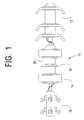
- FIG. 1is an elevational view of a typical smart pig of the type with which the self-tracking sensor suspension mechanism of the invention would be used;
- FIG. 2are views of the self-tracking sensor suspension mechanism of the invention shown in various applications during inspection of a pipeline.
- a typical smart pigdesignated generally as 10 and having a tractor or drive section 12 a magnetizer section 14 and a data storage section 16 or recorder.
- the magnetizer sectionhas a plurality of sensors 18 mounted on a body portion 20 of the magnetizer section.
- the tractor portion 12pulls the magnetizer, recorder, and associated sensors through the pipeline where MFL data is obtained by the sensors 18 for storage in the data storage section 16 .
- Thisis conventional practice and does not constitute a part of the invention.
- the sensor suspension mechanismis designated generally as 22 and is shown in association with a pipeline interior designated in cross-section as P.
- the suspension mechanism 22has a base 24 that is secured, as by welding or fastening (not shown) to the body portion of the magnetizer section 20 , which is shown in FIG. 1 and described above.
- a pin 26that extends through the base 24 and a pivot link 28 permits pivoting of the link 28 about the axis of the pin 26 .
- a spring 30is connected to the base and urges the link 28 away from the body portion 20 of the magnetizer 14 , and toward the interior surface of the pipe P.
- a trailer arm 32mounted on pin 34 for rotation relative to the link 28 .
- the trailer arm 32is urged by spring 36 away from the body portion 20 and into engagement with the interior surface of the pipeline.
- a sensor 38is mounted in the trailing arm 32 and is in engagement with the interior of the pipeline P.
- curvature of the pipeline interiordoes not impair contact of the sensor 38 with the interior pipeline surface.
Landscapes
- Engineering & Computer Science (AREA)
- Mechanical Engineering (AREA)
- General Engineering & Computer Science (AREA)
- Investigating Or Analyzing Materials By The Use Of Ultrasonic Waves (AREA)
- Investigating Or Analyzing Materials By The Use Of Magnetic Means (AREA)
- User Interface Of Digital Computer (AREA)
Abstract
Description
Claims (5)
Priority Applications (8)
| Application Number | Priority Date | Filing Date | Title |
|---|---|---|---|
| US09/677,883US6640655B1 (en) | 2000-10-03 | 2000-10-03 | Self tracking sensor suspension mechanism |
| DE10196734TDE10196734B4 (en) | 2000-10-03 | 2001-09-06 | PIG for moving in a pipeline |
| PCT/US2001/027528WO2002029312A2 (en) | 2000-10-03 | 2001-09-06 | Self tracking sensor suspension mechanism |
| AU2001288761AAU2001288761A1 (en) | 2000-10-03 | 2001-09-06 | Self tracking sensor suspension mechanism |
| GB0306397AGB2386660B8 (en) | 2000-10-03 | 2001-09-06 | Self tracking sensor suspension mechanism |
| CA002423277ACA2423277C (en) | 2000-10-03 | 2001-09-06 | Self tracking sensor suspension mechanism |
| ARP010104622AAR030824A1 (en) | 2000-10-03 | 2001-10-01 | A SUSPENSION SENSOR, SELF-MONITORING MECHANISM |
| CNB038018896ACN100397329C (en) | 2000-10-03 | 2003-08-21 | Systems and methods for providing adequately minimized applications |
Applications Claiming Priority (1)
| Application Number | Priority Date | Filing Date | Title |
|---|---|---|---|
| US09/677,883US6640655B1 (en) | 2000-10-03 | 2000-10-03 | Self tracking sensor suspension mechanism |
Publications (1)
| Publication Number | Publication Date |
|---|---|
| US6640655B1true US6640655B1 (en) | 2003-11-04 |
Family
ID=24720476
Family Applications (1)
| Application Number | Title | Priority Date | Filing Date |
|---|---|---|---|
| US09/677,883Expired - LifetimeUS6640655B1 (en) | 2000-10-03 | 2000-10-03 | Self tracking sensor suspension mechanism |
Country Status (8)
| Country | Link |
|---|---|
| US (1) | US6640655B1 (en) |
| CN (1) | CN100397329C (en) |
| AR (1) | AR030824A1 (en) |
| AU (1) | AU2001288761A1 (en) |
| CA (1) | CA2423277C (en) |
| DE (1) | DE10196734B4 (en) |
| GB (1) | GB2386660B8 (en) |
| WO (1) | WO2002029312A2 (en) |
Cited By (15)
| Publication number | Priority date | Publication date | Assignee | Title |
|---|---|---|---|---|
| US6847207B1 (en) | 2004-04-15 | 2005-01-25 | Tdw Delaware, Inc. | ID-OD discrimination sensor concept for a magnetic flux leakage inspection tool |
| US20070223643A1 (en)* | 2006-03-24 | 2007-09-27 | Tadashi Yamane | Nondestructive inspection apparatus |
| US20080011063A1 (en)* | 2004-07-01 | 2008-01-17 | Smith Derek R | Sensor Finger Module For A Pipeline Inspection Tool |
| US20080173109A1 (en)* | 2007-01-19 | 2008-07-24 | Cogen William | Pipeline inspection apparatus and method using radio frequency identification and inertial navigation |
| US20090199662A1 (en)* | 2008-02-11 | 2009-08-13 | Hoyt Philip M | Flangeless canister for in-line inspection tool |
| US20100060273A1 (en)* | 2004-12-22 | 2010-03-11 | Pii Limited Atley Way | Sensor system for an in-line inspection tool |
| WO2010067162A1 (en)* | 2008-12-12 | 2010-06-17 | Ecopetrol S.A. | Intelligent tool for detecting perforations and interpretation of data online |
| US7798023B1 (en) | 2008-02-11 | 2010-09-21 | Electromechanical Technologies, Inc. | Linkage assembly for in-line inspection tool |
| US8020460B1 (en) | 2008-02-11 | 2011-09-20 | Hoyt Philip M | Sensor housing and mount for in-line inspection tool |
| CN105319263A (en)* | 2015-11-25 | 2016-02-10 | 中国船舶重工集团公司第七二二研究所 | Beacon detection device |
| US20160231279A1 (en)* | 2015-02-10 | 2016-08-11 | Philip M. Hoyt | Linkage assembly for in-line inspection tool |
| US9495077B2 (en) | 2011-04-26 | 2016-11-15 | Sharp Kabushiki Kaisha | Display device, display method, and non-transitory computer-readable recording medium |
| US10401325B2 (en) | 2016-08-11 | 2019-09-03 | Novitech, Inc. | Magnetizers for pigging tools |
| US10458822B2 (en) | 2016-07-11 | 2019-10-29 | Entegra LLP | Dynamic spacer for a smart pipeline inspection gauge |
| US11913783B1 (en)* | 2019-11-22 | 2024-02-27 | Cypress In-Line Inspection, LLC | Geometry sensor for inline inspection tool |
Families Citing this family (28)
| Publication number | Priority date | Publication date | Assignee | Title |
|---|---|---|---|---|
| RU2248498C1 (en)* | 2003-10-29 | 2005-03-20 | ЗАО "Нефтегазкомплектсервис" | Flaw detector for testing pipe from inside |
| GB2432894B (en)* | 2004-12-22 | 2007-07-11 | Pii Ltd | A sensor system for an in-line inspection tool |
| GB0505506D0 (en)* | 2005-03-17 | 2005-04-27 | Pll Ltd | A sensor system for an in-line inspection tool |
| FR2931924B1 (en)* | 2008-06-02 | 2014-12-05 | Gaz De France | METHOD FOR DETERMINING THE INTEGRITY OF A PRESSURIZED FLUID TRANSPORT STEEL PIPING |
| US20110126087A1 (en)* | 2008-06-27 | 2011-05-26 | Andreas Matthias Aust | Graphical user interface for non mouse-based activation of links |
| US8612874B2 (en) | 2010-12-23 | 2013-12-17 | Microsoft Corporation | Presenting an application change through a tile |
| US8689123B2 (en) | 2010-12-23 | 2014-04-01 | Microsoft Corporation | Application reporting in an application-selectable user interface |
| CN102156615B (en)* | 2011-04-01 | 2015-11-25 | 北京奇虎科技有限公司 | A kind of suspension window displaying method and device |
| US9104307B2 (en) | 2011-05-27 | 2015-08-11 | Microsoft Technology Licensing, Llc | Multi-application environment |
| US20130057587A1 (en) | 2011-09-01 | 2013-03-07 | Microsoft Corporation | Arranging tiles |
| US9146670B2 (en) | 2011-09-10 | 2015-09-29 | Microsoft Technology Licensing, Llc | Progressively indicating new content in an application-selectable user interface |
| US9223472B2 (en) | 2011-12-22 | 2015-12-29 | Microsoft Technology Licensing, Llc | Closing applications |
| CN102799380A (en)* | 2012-07-13 | 2012-11-28 | 杭州边锋网络技术有限公司 | Desktop shortcut control system and method |
| US9483549B2 (en)* | 2013-09-30 | 2016-11-01 | Microsoft Technology Licensing, Llc | Persisting state at scale across browser sessions |
| CN103729182B (en)* | 2013-12-27 | 2017-10-27 | 广州华多网络科技有限公司 | Client-based window minimizes method and apparatus |
| CN105359094A (en) | 2014-04-04 | 2016-02-24 | 微软技术许可有限责任公司 | Extensible Application Representation |
| EP3126941A4 (en)* | 2014-04-04 | 2017-07-26 | Microsoft Technology Licensing, LLC | Expandable application representation and sending content |
| KR20160143784A (en) | 2014-04-10 | 2016-12-14 | 마이크로소프트 테크놀로지 라이센싱, 엘엘씨 | Slider cover for computing devices |
| KR102107275B1 (en) | 2014-04-10 | 2020-05-06 | 마이크로소프트 테크놀로지 라이센싱, 엘엘씨 | Collapsible shell cover for computing device |
| US10949075B2 (en) | 2014-11-06 | 2021-03-16 | Microsoft Technology Licensing, Llc | Application command control for small screen display |
| US20160132992A1 (en) | 2014-11-06 | 2016-05-12 | Microsoft Technology Licensing, Llc | User interface scaling for devices based on display size |
| CN105117287A (en)* | 2015-09-23 | 2015-12-02 | 北京超卓科技有限公司 | Graphical user interface and implementation method and user interaction method thereof |
| CN105987285B (en)* | 2016-06-22 | 2019-01-15 | 天津大学 | A kind of rapid detection method of pipeline abnormal point |
| CN109869637B (en)* | 2017-12-05 | 2021-03-12 | 中国石油化工股份有限公司华北油气分公司采气一厂 | Adjustable suspension device in pipeline |
| US11579118B2 (en) | 2019-06-03 | 2023-02-14 | Tdw Delaware, Inc. | Single point contact triaxial sensor head for an inline inspection tool |
| CN110780962B (en)* | 2019-10-15 | 2022-02-01 | 四川长虹电器股份有限公司 | Application window title bar and window control display method in X window manager |
| CN111176813B (en)* | 2019-12-28 | 2024-06-07 | 深圳市优必选科技股份有限公司 | Running mode dynamic switching method and device |
| CN111677975B (en)* | 2020-07-03 | 2021-11-02 | 廊坊中油朗威工程项目管理有限公司 | Detection device and long-distance pipeline cleaner |
Citations (9)
| Publication number | Priority date | Publication date | Assignee | Title |
|---|---|---|---|---|
| US2812587A (en)* | 1954-07-13 | 1957-11-12 | Schlumberger Well Surv Corp | Borehole calipering apparatus |
| US3460028A (en) | 1967-11-03 | 1969-08-05 | American Mach & Foundry | Pipeline inspection apparatus with means for correlating the recorded defect signals with the angular position within the pipeline at which they were generated |
| US3593112A (en)* | 1969-12-22 | 1971-07-13 | Varo | Solid-state ac power control apparatus |
| US3940855A (en)* | 1974-07-19 | 1976-03-02 | T. D. Williamson, Inc. | Pipeline pig |
| US4105972A (en) | 1976-04-09 | 1978-08-08 | British Gas Corporation | Pipeline inspection vehicle for detecting defects in pipeline walls |
| US4205266A (en)* | 1977-04-13 | 1980-05-27 | Dresser Industries, Inc. | Method and apparatus to determine the proximity of a permanent magnet using a magnetometer |
| US4576097A (en) | 1981-04-27 | 1986-03-18 | Foster John L | Pipeline inspection vehicles |
| US6023986A (en) | 1997-03-24 | 2000-02-15 | Bj Services Company | Magnetic flux leakage inspection tool for pipelines |
| US6076407A (en)* | 1998-05-15 | 2000-06-20 | Framatome Technologies, Inc. | Pipe inspection probe |
Family Cites Families (4)
| Publication number | Priority date | Publication date | Assignee | Title |
|---|---|---|---|---|
| US5959625A (en)* | 1997-08-04 | 1999-09-28 | Siemens Building Technologies, Inc. | Method and system for facilitating navigation among software applications and improved screen viewing |
| US6385662B1 (en)* | 1997-10-03 | 2002-05-07 | Ericsson Inc. | Method of processing information using a personal communication assistant |
| US6429883B1 (en)* | 1999-09-03 | 2002-08-06 | International Business Machines Corporation | Method for viewing hidden entities by varying window or graphic object transparency |
| US7620911B2 (en)* | 2001-07-12 | 2009-11-17 | Autodesk, Inc. | Collapsible dialog window |
- 2000
- 2000-10-03USUS09/677,883patent/US6640655B1/ennot_activeExpired - Lifetime
- 2001
- 2001-09-06WOPCT/US2001/027528patent/WO2002029312A2/enactiveApplication Filing
- 2001-09-06DEDE10196734Tpatent/DE10196734B4/ennot_activeExpired - Lifetime
- 2001-09-06CACA002423277Apatent/CA2423277C/ennot_activeExpired - Fee Related
- 2001-09-06AUAU2001288761Apatent/AU2001288761A1/ennot_activeAbandoned
- 2001-09-06GBGB0306397Apatent/GB2386660B8/ennot_activeExpired - Fee Related
- 2001-10-01ARARP010104622Apatent/AR030824A1/enactiveIP Right Grant
- 2003
- 2003-08-21CNCNB038018896Apatent/CN100397329C/ennot_activeExpired - Fee Related
Patent Citations (9)
| Publication number | Priority date | Publication date | Assignee | Title |
|---|---|---|---|---|
| US2812587A (en)* | 1954-07-13 | 1957-11-12 | Schlumberger Well Surv Corp | Borehole calipering apparatus |
| US3460028A (en) | 1967-11-03 | 1969-08-05 | American Mach & Foundry | Pipeline inspection apparatus with means for correlating the recorded defect signals with the angular position within the pipeline at which they were generated |
| US3593112A (en)* | 1969-12-22 | 1971-07-13 | Varo | Solid-state ac power control apparatus |
| US3940855A (en)* | 1974-07-19 | 1976-03-02 | T. D. Williamson, Inc. | Pipeline pig |
| US4105972A (en) | 1976-04-09 | 1978-08-08 | British Gas Corporation | Pipeline inspection vehicle for detecting defects in pipeline walls |
| US4205266A (en)* | 1977-04-13 | 1980-05-27 | Dresser Industries, Inc. | Method and apparatus to determine the proximity of a permanent magnet using a magnetometer |
| US4576097A (en) | 1981-04-27 | 1986-03-18 | Foster John L | Pipeline inspection vehicles |
| US6023986A (en) | 1997-03-24 | 2000-02-15 | Bj Services Company | Magnetic flux leakage inspection tool for pipelines |
| US6076407A (en)* | 1998-05-15 | 2000-06-20 | Framatome Technologies, Inc. | Pipe inspection probe |
Cited By (28)
| Publication number | Priority date | Publication date | Assignee | Title |
|---|---|---|---|---|
| US6847207B1 (en) | 2004-04-15 | 2005-01-25 | Tdw Delaware, Inc. | ID-OD discrimination sensor concept for a magnetic flux leakage inspection tool |
| US20080011063A1 (en)* | 2004-07-01 | 2008-01-17 | Smith Derek R | Sensor Finger Module For A Pipeline Inspection Tool |
| US8291780B2 (en)* | 2004-07-01 | 2012-10-23 | Pii Limited | Sensor finger module for a pipeline inspection tool |
| US20100060273A1 (en)* | 2004-12-22 | 2010-03-11 | Pii Limited Atley Way | Sensor system for an in-line inspection tool |
| US8373411B2 (en)* | 2004-12-22 | 2013-02-12 | Pii Limited | Sensor system for an in-line inspection tool |
| US20070223643A1 (en)* | 2006-03-24 | 2007-09-27 | Tadashi Yamane | Nondestructive inspection apparatus |
| US7421915B2 (en)* | 2006-03-24 | 2008-09-09 | The Tokyo Electric Power Company, Incorporated | Nondestructive inspection apparatus |
| US8001858B2 (en) | 2007-01-19 | 2011-08-23 | Cogen William | Pipeline inspection apparatus and method using radio frequency identification and inertial navigation |
| US20080173109A1 (en)* | 2007-01-19 | 2008-07-24 | Cogen William | Pipeline inspection apparatus and method using radio frequency identification and inertial navigation |
| US8689653B2 (en) | 2007-01-19 | 2014-04-08 | William COGEN | Pipeline inspection apparatus and method using radio frequency identification and inertial navigation |
| US7733085B2 (en) | 2008-02-11 | 2010-06-08 | Electromechanical Technologies, Inc. | Flangeless canister for in-line inspection tool |
| US7798023B1 (en) | 2008-02-11 | 2010-09-21 | Electromechanical Technologies, Inc. | Linkage assembly for in-line inspection tool |
| US20090199662A1 (en)* | 2008-02-11 | 2009-08-13 | Hoyt Philip M | Flangeless canister for in-line inspection tool |
| US8020460B1 (en) | 2008-02-11 | 2011-09-20 | Hoyt Philip M | Sensor housing and mount for in-line inspection tool |
| WO2010067162A1 (en)* | 2008-12-12 | 2010-06-17 | Ecopetrol S.A. | Intelligent tool for detecting perforations and interpretation of data online |
| US8892378B2 (en) | 2008-12-12 | 2014-11-18 | Ecopetrol S.A. | Intelligent tool for detecting perforations and interpretation of data online |
| US9495077B2 (en) | 2011-04-26 | 2016-11-15 | Sharp Kabushiki Kaisha | Display device, display method, and non-transitory computer-readable recording medium |
| US9804132B2 (en)* | 2015-02-10 | 2017-10-31 | Philip M. Hoyt | Linkage assembly for in-line inspection tool |
| US20160231279A1 (en)* | 2015-02-10 | 2016-08-11 | Philip M. Hoyt | Linkage assembly for in-line inspection tool |
| CN105319263A (en)* | 2015-11-25 | 2016-02-10 | 中国船舶重工集团公司第七二二研究所 | Beacon detection device |
| CN105319263B (en)* | 2015-11-25 | 2018-05-22 | 中国船舶重工集团公司第七二二研究所 | A kind of beacon detection device |
| US10458822B2 (en) | 2016-07-11 | 2019-10-29 | Entegra LLP | Dynamic spacer for a smart pipeline inspection gauge |
| US10401325B2 (en) | 2016-08-11 | 2019-09-03 | Novitech, Inc. | Magnetizers for pigging tools |
| US10705051B2 (en) | 2016-08-11 | 2020-07-07 | Novitech, Inc. | Magnetizers for pigging tools |
| US10969366B2 (en) | 2016-08-11 | 2021-04-06 | Novitech Inc. | Magnetizers for pigging tools including a cushion |
| US11346810B2 (en) | 2016-08-11 | 2022-05-31 | Novitech Inc. | Magnetizer with cushion |
| US11946903B2 (en) | 2016-08-11 | 2024-04-02 | Novitech, Inc. | Magnetizer with cushion |
| US11913783B1 (en)* | 2019-11-22 | 2024-02-27 | Cypress In-Line Inspection, LLC | Geometry sensor for inline inspection tool |
Also Published As
| Publication number | Publication date |
|---|---|
| GB2386660A8 (en) | 2011-04-27 |
| AR030824A1 (en) | 2003-09-03 |
| WO2002029312A3 (en) | 2002-10-24 |
| GB0306397D0 (en) | 2003-04-23 |
| GB2386660A (en) | 2003-09-24 |
| CA2423277C (en) | 2009-06-02 |
| DE10196734B4 (en) | 2010-11-25 |
| CN100397329C (en) | 2008-06-25 |
| CN1735856A (en) | 2006-02-15 |
| DE10196734T1 (en) | 2003-09-11 |
| GB2386660B (en) | 2004-04-21 |
| WO2002029312A2 (en) | 2002-04-11 |
| CA2423277A1 (en) | 2002-04-11 |
| AU2001288761A1 (en) | 2002-04-15 |
| GB2386660B8 (en) | 2011-04-27 |
Similar Documents
| Publication | Publication Date | Title |
|---|---|---|
| US6640655B1 (en) | Self tracking sensor suspension mechanism | |
| US11021198B2 (en) | Compact magnetic crawler vehicle with anti-rocking supports | |
| US20190360976A1 (en) | Pipeline inspection systems and methods | |
| US10705051B2 (en) | Magnetizers for pigging tools | |
| US20160116316A1 (en) | Ultrasonic Flow Meter | |
| US8020460B1 (en) | Sensor housing and mount for in-line inspection tool | |
| US20130133429A1 (en) | Apparatus for pipeline inspection | |
| JPH0814574B2 (en) | Pipeline inspection equipment | |
| US20050223825A1 (en) | Method to prevent rotation of caliper tools and other pipeline tools | |
| US7859256B1 (en) | Defect discriminator for in-line inspection tool | |
| US20120325004A1 (en) | Apparatus for pipeline inspection and method of pipeline inspection | |
| JP2023551298A (en) | Magnetic crawler with three articulated wheels for movement on pipes | |
| CA1081941A (en) | Probing device for the interior of pipelines | |
| US8291780B2 (en) | Sensor finger module for a pipeline inspection tool | |
| CA2125618A1 (en) | Support device for in-line pipe inspection tool | |
| CN205581059U (en) | Probe voussoir fixture who is fit for pipeline ultrasonic non -destructive testing | |
| JPH0666776A (en) | Pipe interior inspecting pig | |
| CA2992363C (en) | Magnetizer for pigging tools | |
| US20240369172A1 (en) | Segment for a Sensor-Carrier Body of a Pig for Inspecting a Pipeline | |
| CN212158546U (en) | Detection arm structure and detector having the same | |
| US20200378923A1 (en) | Single Point Contact Triaxial Sensor Head For ILI | |
| RU227286U1 (en) | In-line flaw detector sensor block | |
| RU224858U1 (en) | Design of an in-line flaw detector sensor unit | |
| JP2001235090A (en) | In-pipe inspection equipment | |
| KR20250077015A (en) | Inspection Device of Pipe |
Legal Events
| Date | Code | Title | Description |
|---|---|---|---|
| AS | Assignment | Owner name:TUBOSCOPE I/P, INC., TEXAS Free format text:ASSIGNMENT OF ASSIGNORS INTEREST;ASSIGNORS:MANZAK, PAUL T.;TORRES, CARL R. JR.;REEL/FRAME:011182/0208 Effective date:20000928 | |
| STCF | Information on status: patent grant | Free format text:PATENTED CASE | |
| FPAY | Fee payment | Year of fee payment:4 | |
| AS | Assignment | Owner name:VARCO I/P, INC., TEXAS Free format text:CHANGE OF NAME;ASSIGNOR:TUBOSCOPE I/P, INC.;REEL/FRAME:023861/0738 Effective date:20010205 | |
| AS | Assignment | Owner name:NDT SYSTEMS & SERVICES AG, GERMANY Free format text:ASSIGNMENT OF ASSIGNORS INTEREST;ASSIGNORS:VARCO I/P INC.;NDT SYSTEMS & SERVICES (AMERICA) INC.;REEL/FRAME:023870/0042;SIGNING DATES FROM 20080909 TO 20090528 | |
| AS | Assignment | Owner name:VARCO, L.P.,TEXAS Free format text:MERGER;ASSIGNOR:TUBOSCOPE VETCO INTERNATIONAL, L.P.;REEL/FRAME:023892/0150 Effective date:20001220 | |
| FPAY | Fee payment | Year of fee payment:8 | |
| FPAY | Fee payment | Year of fee payment:12 |