US6640547B2 - Effusion cooled transition duct with shaped cooling holes - Google Patents
Effusion cooled transition duct with shaped cooling holesDownload PDFInfo
- Publication number
- US6640547B2 US6640547B2US10/280,173US28017302AUS6640547B2US 6640547 B2US6640547 B2US 6640547B2US 28017302 AUS28017302 AUS 28017302AUS 6640547 B2US6640547 B2US 6640547B2
- Authority
- US
- United States
- Prior art keywords
- transition duct
- wall
- cooling
- cooling holes
- diameter
- Prior art date
- Legal status (The legal status is an assumption and is not a legal conclusion. Google has not performed a legal analysis and makes no representation as to the accuracy of the status listed.)
- Expired - Lifetime
Links
Images


Classifications
- F—MECHANICAL ENGINEERING; LIGHTING; HEATING; WEAPONS; BLASTING
- F01—MACHINES OR ENGINES IN GENERAL; ENGINE PLANTS IN GENERAL; STEAM ENGINES
- F01D—NON-POSITIVE DISPLACEMENT MACHINES OR ENGINES, e.g. STEAM TURBINES
- F01D9/00—Stators
- F01D9/02—Nozzles; Nozzle boxes; Stator blades; Guide conduits, e.g. individual nozzles
- F01D9/023—Transition ducts between combustor cans and first stage of the turbine in gas-turbine engines; their cooling or sealings
- F—MECHANICAL ENGINEERING; LIGHTING; HEATING; WEAPONS; BLASTING
- F02—COMBUSTION ENGINES; HOT-GAS OR COMBUSTION-PRODUCT ENGINE PLANTS
- F02C—GAS-TURBINE PLANTS; AIR INTAKES FOR JET-PROPULSION PLANTS; CONTROLLING FUEL SUPPLY IN AIR-BREATHING JET-PROPULSION PLANTS
- F02C3/00—Gas-turbine plants characterised by the use of combustion products as the working fluid
- F02C3/14—Gas-turbine plants characterised by the use of combustion products as the working fluid characterised by the arrangement of the combustion chamber in the plant
- F—MECHANICAL ENGINEERING; LIGHTING; HEATING; WEAPONS; BLASTING
- F02—COMBUSTION ENGINES; HOT-GAS OR COMBUSTION-PRODUCT ENGINE PLANTS
- F02C—GAS-TURBINE PLANTS; AIR INTAKES FOR JET-PROPULSION PLANTS; CONTROLLING FUEL SUPPLY IN AIR-BREATHING JET-PROPULSION PLANTS
- F02C7/00—Features, components parts, details or accessories, not provided for in, or of interest apart form groups F02C1/00 - F02C6/00; Air intakes for jet-propulsion plants
- F02C7/12—Cooling of plants
- F02C7/16—Cooling of plants characterised by cooling medium
- F02C7/18—Cooling of plants characterised by cooling medium the medium being gaseous, e.g. air
- F—MECHANICAL ENGINEERING; LIGHTING; HEATING; WEAPONS; BLASTING
- F23—COMBUSTION APPARATUS; COMBUSTION PROCESSES
- F23R—GENERATING COMBUSTION PRODUCTS OF HIGH PRESSURE OR HIGH VELOCITY, e.g. GAS-TURBINE COMBUSTION CHAMBERS
- F23R3/00—Continuous combustion chambers using liquid or gaseous fuel
- F23R3/42—Continuous combustion chambers using liquid or gaseous fuel characterised by the arrangement or form of the flame tubes or combustion chambers
- F23R3/46—Combustion chambers comprising an annular arrangement of several essentially tubular flame tubes within a common annular casing or within individual casings
- F—MECHANICAL ENGINEERING; LIGHTING; HEATING; WEAPONS; BLASTING
- F05—INDEXING SCHEMES RELATING TO ENGINES OR PUMPS IN VARIOUS SUBCLASSES OF CLASSES F01-F04
- F05D—INDEXING SCHEME FOR ASPECTS RELATING TO NON-POSITIVE-DISPLACEMENT MACHINES OR ENGINES, GAS-TURBINES OR JET-PROPULSION PLANTS
- F05D2260/00—Function
- F05D2260/20—Heat transfer, e.g. cooling
- F05D2260/202—Heat transfer, e.g. cooling by film cooling
Definitions
- This inventionapplies to the combustor section of gas turbine engines used in powerplants to generate electricity. More specifically, this invention relates to the structure that transfers hot combustion gases from a can-annular combustor to the inlet of a turbine.
- a plurality of combustorsis arranged in an annular array about the engine.
- the hot gases exiting the combustorsare utilized to turn the turbine, which is coupled to a shaft that drives a generator for generating electricity.
- the hot gasesare transferred from the combustor to the turbine by a transition duct. Due to the position of the combustors relative to the turbine inlet, the transition duct must change cross-sectional shape from a generally cylindrical shape at the combustor exit to a generally rectangular shape at the turbine inlet, as well as change radial position, since the combustors are typically mounted radially outboard of the turbine.
- transition ductsare typically cooled, usually by air, either with internal cooling channels or impingement cooling.
- Catastrophic crackinghas been seen in internally air-cooled transition ducts with excessive geometry changes that operate in this high temperature environment. Through extensive analysis, this cracking can be attributed to a variety of factors. Specifically, high steady stresses have been found in the region around the aft end of the transition duct where sharp geometry changes occur. In addition stress concentrations have been found that can be attributed to sharp corners where cooling holes intersect the internal cooling channels in the transition duct. Further complicating the high stress conditions are extreme temperature differences between components of the transition duct.
- FIG. 1is a perspective view of a prior art transition duct.
- FIG. 2is a cross section view of a prior art transition duct.
- FIG. 3is a perspective view of a portion of the prior art transition duct cooling arrangement.
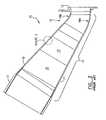
- FIG. 4is a perspective view of the present invention transition duct.
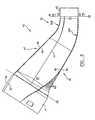
- FIG. 5is a cross section view of the present invention transition duct.
- FIG. 6is a perspective view of a portion of the present invention transition duct cooling arrangement.
- FIG. 7is a cross section view of an alternate embodiment of the present invention disclosing an alternate type of cooling holes for a transition duct.
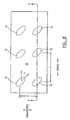
- FIG. 8is a top view of a portion of an alternate embodiment of the present invention disclosing an alternate type of cooling holes for a transition duct.
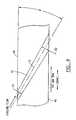
- FIG. 9is a section view taken through the portion of an alternate embodiment of the present invention shown in FIG. 8, disclosing an alternate type of cooling holes for a transition duct.
- transition duct 10of the prior art is shown in perspective view.
- the transition ductincludes a generally cylindrical inlet flange 11 and a generally rectangular exit frame 12 .
- the can-annular combustor(not shown) engages transition duct 10 at inlet flange 11 .
- the hot combustion gasespass through transition duct 10 and pass through exit frame 12 and into the turbine (not shown).
- Transition duct 10is mounted to the engine by a forward mounting means 13 , fixed to the outside surface of inlet flange 11 and mounted to the turbine by an aft mounting means 14 , which is fixed to exit frame 12 .
- a panel assembly 15connects inlet flange 11 to exit frame 12 and provides the change in geometric shape for transition duct 10 . This change in geometric shape is shown in greater detail in FIG. 2 .
- the panel assembly 15which extends between inlet flange 11 and exit frame 12 and includes a first panel 17 and a second panel 18 , tapers from a generally cylindrical shape at inlet flange 11 to a generally rectangular shape at exit frame 12 . The majority of this taper occurs towards the aft end of panel assembly 15 near exit frame 12 in a region of curvature 16 .
- This region of curvatureincludes two radii of curvature, 16 A on first panel 17 and 16 B on second panel 18 .
- Panels 17 and 18each consist of a plurality of layers of sheet metal pressed together to form channels in between the layers of metal. Air passes through these channels to cool transition duct 10 and maintain metal temperatures of panel assembly 15 within an acceptable range. This cooling configuration is detailed in FIG. 3 .
- FIG. 3A cutaway view of panel assembly 15 with details of the channel cooling arrangement is shown in detail in FIG. 3 .
- Channel 30is formed between layers 17 A and 17 B of panel 17 within panel assembly 15 . Cooling air enters duct 10 through inlet hole 31 , passes through channel 30 , thereby cooling panel layer 17 A, and exits into duct gaspath 19 through exit hole 32 .
- This cooling methodprovides an adequate amount of cooling in local regions, yet has drawbacks in terms of manufacturing difficulty and cost, and has been found to contribute to cracking of ducts when combined with the geometry and operating conditions of the prior art.
- the present inventionan improved transition duct incorporating effusion cooling and geometry changes, is disclosed below and shown in FIGS. 4-6.
- An improved transition duct 40includes a generally cylindrical inlet flange 41 , a generally rectangular aft end frame 42 , and a panel assembly 45 .
- Panel assembly 45includes a first panel 46 and a second panel 47 , each constructed from a single sheet of metal at least 0.125 inches thick.
- the panel assembly, inlet flange, and end frameare typically constructed from a nick-base superalloy such as Inconel 625.
- Panel 46is fixed to panel 47 by a means such as welding, forming a duct having an inner wall 48 , an outer wall 49 , a generally cylindrical inlet end 50 , and a generally rectangular exit end 51 .
- Inlet flange 41is fixed to panel assembly 45 at cylindrical inlet end 50 while aft end frame 42 is fixed to panel assembly 45 at rectangular exit end 51 .
- Transition duct 40includes a region of curvature 52 where the generally cylindrical duct tapers into the generally rectangular shape.
- a first radius of curvature 52 A, located along first panel 46is at least 10 inches while a second radius of curvature 52 B, located along second panel 47 , is at least 3 inches.
- This region of curvatureis greater than that of the prior art and serves to provide a more gradual curvature of panel assembly 45 towards end frame 42 .
- a more gradual curvatureallows operating stresses to spread throughout the panel assembly and not concentrate in one section. The result is lower operating stresses for transition duct 40 .
- the improved transition duct 40utilizes an effusion-type cooling scheme consisting of a plurality of cooling holes 60 extending from outer wall 49 to inner wall 48 of panel assembly 45 .
- Cooling holes 60are drilled, at a diameter D, in a downstream direction towards aft end frame 42 , with the holes forming an acute angle ⁇ relative to outer wall 49 .
- Angled cooling holesprovide an increase in cooling effectiveness for a known amount of cooling air due to the extra length of the hole, and hence extra material being cooled.
- the spacing of the cooling holesis a function of the hole diameter, such that there is a greater distance between holes as the hole size increases, for a known thickness of material.
- Acceptable cooling schemes for the present inventioncan vary based on the operating conditions, but one such scheme includes cooling holes 60 with diameter D of at least 0.040 inches at a maximum angle ⁇ to outer wall 49 of 30 degrees with the hole-to-hole spacing, P, in the axial and transverse direction following the relationship: P ⁇ (15 ⁇ D). Such a hole spacing will result in a surface area coverage by cooling holes of at least 20%.
- effusion-type coolingeliminates the need for multiple layers of sheet metal with internal cooling channels and holes that can be complex and costly to manufacture.
- effusion-type coolingprovides a more uniform cooling pattern throughout the transition duct. This improved cooling scheme in combination with the more gradual geometric curvature disclosed will reduce operating stresses in the transition duct and produce a more reliable component requiring less frequent replacement.
- a transition duct containing a plurality of tapered cooling holesis disclosed. It has been determined that increasing the hole diameter towards the cooling hole exit region, which is proximate the hot combustion gases of a transition duct, reduces cooling fluid exit velocity and potential film blow-off.
- cooling fluidnot only cools the panel assembly wall as it passes through the hole, but the hole is angled in order to lay a film of cooling fluid along the surface of the panel assembly inner wall in order to provide surface cooling in between rows of cooling holes.
- Film blow-offoccurs when the velocity of a cooling fluid exiting a cooling hole is high enough to penetrate into the main stream of hot combustion gases.
- the cooling fluidmixes with the hot combustion gases instead of remaining as a layer of cooling film along the panel assembly inner wall to actively cool the inner wall in between rows of cooling holes.
- the cross sectional area of the cooling hole at the exit planeis increased, and for a given amount of cooling fluid, the exit velocity will decrease compared to the entrance velocity. Therefore, penetration of the cooling fluid into the flow of hot combustion gases is reduced and the cooling fluid tends to remain along the panel assembly inner wall of the transition duct, thereby providing an improved film of cooling fluid, which results in a more efficient cooling design for a transition duct.
- Transition duct 40includes a panel assembly 45 formed from first panel 46 and second panel 47 , which are each fabricated from a single sheet of metal, and fixed together by a means such as welding along a plurality of axial seams 57 to form panel assembly 45 .
- panel assembly 45contains an inner wall 48 and outer wall 49 and a thickness therebetween.
- the alternate embodimentcontains a generally cylindrical inlet end 50 and a generally rectangular exit end 51 with inlet end 50 defining a first plane 55 and exit end 51 defining a second plane 56 with first plane 55 oriented at an angle relative to second plane 56 .
- Fixed to inlet end 50 of panel assembly 45is a generally cylindrical inlet sleeve 41 having an inner diameter 53 and outer diameter 54
- fixed to outlet end 51 of panel assembly 45is a generally rectangular aft end frame 42 .
- panel assembly 45 , inlet sleeve 41 , and aft end frame 42are manufactured from a nickel-base superalloy such a Inconnel 625 with panel assembly 45 having a thickness of at least 0.125 inches.
- transition duct 40contains a plurality of cooling holes 70 located in panel assembly 45 , with cooling holes 70 found in both first panel 46 and second panel 47 .
- Each of cooling holes 70are separated from an adjacent cooling hole in the axial and transverse direction by a distance P as shown in FIG. 8, with the axial direction being substantially parallel to the flow of gases through transition duct 40 and the transverse direction generally perpendicular to the axial direction.
- Cooling holes 70are spaced throughout panel assembly 45 in such a manner as to provide uniform cooling to panel assembly 45 . It has been determined that for this configuration, the most effective distance P between cooling holes 70 is at least 0.2 inches with a maximum distance P of 2.0 inches in the axial direction and 0 . 4 inches in the transverse direction.
- cooling holes 70extend from outer wall 49 to inner wall 48 of panel assembly 45 with each of cooling holes 70 drilled at an acute surface angle ⁇ relative to outer wall 49 .
- Cooling holes 70are drilled in panel assembly 45 from outer wall 49 towards inner wall 48 , such that when in operation, cooling fluid flows towards the aft end of transition duct 40 .
- cooling holes 70are also drilled at a transverse angle ⁇ , as shown in FIG. 8, where ⁇ is measured from the axial direction, which is generally parallel to the flow of hot combustion gases.
- acute surface angle ⁇ranges between 15 degrees and 30 degrees as measured from outer wall 49 while transverse angle ⁇ measures between 30 degrees and 45 degrees.
- cooling holes 70have a first diameter D 1 and a second diameter D 2 such that both diameters D 1 and D 2 are measured perpendicular to a centerline CL of cooling hole 70 where cooling hole 70 intersects outer wall 49 and inner wall 48 .
- Cooling holes 70are sized such that second diameter D 2 is greater than first diameter D 1 thereby resulting in a generally conical shape. It is preferred that cooling holes 70 have a first diameter D 1 of at least 0.025 inches while having a second diameter D 2 of at least 0.045 inches. Utilizing a generally conical hole results in reduced cooling fluid velocity at second diameter D 2 compared to fluid velocity at first diameter D 1 . A reduction in fluid velocity within cooling hole 70 will allow for the cooling fluid to remain as a film along inner wall 48 once it exits cooling hole 70 . This improved film cooling effectiveness results in improved overall heat transfer and transition duct durability.
Landscapes
- Engineering & Computer Science (AREA)
- Mechanical Engineering (AREA)
- General Engineering & Computer Science (AREA)
- Chemical & Material Sciences (AREA)
- Combustion & Propulsion (AREA)
- Turbine Rotor Nozzle Sealing (AREA)
- Safety Valves (AREA)
- Saccharide Compounds (AREA)
Abstract
Description
Claims (9)
Priority Applications (13)
| Application Number | Priority Date | Filing Date | Title |
|---|---|---|---|
| US09/683,290US6568187B1 (en) | 2001-12-10 | 2001-12-10 | Effusion cooled transition duct |
| US10/280,173US6640547B2 (en) | 2001-12-10 | 2002-10-25 | Effusion cooled transition duct with shaped cooling holes |
| AU2003228742AAU2003228742A1 (en) | 2002-10-25 | 2003-05-01 | Effusion cooled transition duct with shaped cooling holes |
| ES03726511TES2294281T3 (en) | 2002-10-25 | 2003-05-01 | TRANSITION COOLING REFRIGERATED BY ISSUANCE WITH COOLING HOLES IN ONE WAY. |
| MXPA05004420AMXPA05004420A (en) | 2002-10-25 | 2003-05-01 | Effusion cooled transition duct with shaped cooling holes. |
| DE60317920TDE60317920T2 (en) | 2002-10-25 | 2003-05-01 | EFFUSION COOLED TRANSITION CHANNEL WITH SHAPED COOLING HOLES |
| KR1020057007156AKR101044662B1 (en) | 2002-10-25 | 2003-05-01 | Outflow cooling transition duct with molded cooling holes |
| CA2503333ACA2503333C (en) | 2002-10-25 | 2003-05-01 | Effusion cooled transition duct with shaped cooling holes |
| AT03726511TATE380286T1 (en) | 2002-10-25 | 2003-05-01 | EFFUSION COOLED TRANSITION CHANNEL WITH MOLDED COOLING HOLES |
| JP2004548255AJP4382670B2 (en) | 2002-10-25 | 2003-05-01 | Outflow liquid cooling transition duct with shaped cooling holes |
| EP03726511AEP1556596B8 (en) | 2002-10-25 | 2003-05-01 | Effusion cooled transition duct with shaped cooling holes |
| PCT/US2003/013204WO2004040108A1 (en) | 2002-10-25 | 2003-05-01 | Effusion cooled transition duct with shaped cooling holes |
| IL168196AIL168196A (en) | 2002-10-25 | 2005-04-21 | Effusion cooled transition duct with shaped cooling holes |
Applications Claiming Priority (2)
| Application Number | Priority Date | Filing Date | Title |
|---|---|---|---|
| US68329001 | 2001-12-10 | ||
| US10/280,173US6640547B2 (en) | 2001-12-10 | 2002-10-25 | Effusion cooled transition duct with shaped cooling holes |
Related Parent Applications (1)
| Application Number | Title | Priority Date | Filing Date |
|---|---|---|---|
| US09/683,290Continuation-In-PartUS6568187B1 (en) | 2001-12-10 | 2001-12-10 | Effusion cooled transition duct |
Publications (2)
| Publication Number | Publication Date |
|---|---|
| US20030106318A1 US20030106318A1 (en) | 2003-06-12 |
| US6640547B2true US6640547B2 (en) | 2003-11-04 |
Family
ID=32228746
Family Applications (1)
| Application Number | Title | Priority Date | Filing Date |
|---|---|---|---|
| US10/280,173Expired - LifetimeUS6640547B2 (en) | 2001-12-10 | 2002-10-25 | Effusion cooled transition duct with shaped cooling holes |
Country Status (12)
| Country | Link |
|---|---|
| US (1) | US6640547B2 (en) |
| EP (1) | EP1556596B8 (en) |
| JP (1) | JP4382670B2 (en) |
| KR (1) | KR101044662B1 (en) |
| AT (1) | ATE380286T1 (en) |
| AU (1) | AU2003228742A1 (en) |
| CA (1) | CA2503333C (en) |
| DE (1) | DE60317920T2 (en) |
| ES (1) | ES2294281T3 (en) |
| IL (1) | IL168196A (en) |
| MX (1) | MXPA05004420A (en) |
| WO (1) | WO2004040108A1 (en) |
Cited By (39)
| Publication number | Priority date | Publication date | Assignee | Title |
|---|---|---|---|---|
| US20050132708A1 (en)* | 2003-12-22 | 2005-06-23 | Martling Vincent C. | Cooling and sealing design for a gas turbine combustion system |
| US20050204741A1 (en)* | 2004-03-17 | 2005-09-22 | General Electric Company | Turbine combustor transition piece having dilution holes |
| US20060037323A1 (en)* | 2004-08-20 | 2006-02-23 | Honeywell International Inc., | Film effectiveness enhancement using tangential effusion |
| US20060045730A1 (en)* | 2004-08-27 | 2006-03-02 | Pratt & Whitney Canada Corp. | Lightweight annular interturbine duct |
| US20060162314A1 (en)* | 2005-01-27 | 2006-07-27 | Siemens Westinghouse Power Corp. | Cooling system for a transition bracket of a transition in a turbine engine |
| US20060207095A1 (en)* | 2004-01-09 | 2006-09-21 | Honeywell International Inc. | Method for controlling carbon formation on repaired combustor liners |
| US20070169484A1 (en)* | 2006-01-24 | 2007-07-26 | Honeywell International, Inc. | Segmented effusion cooled gas turbine engine combustor |
| US20070180827A1 (en)* | 2006-02-09 | 2007-08-09 | Siemens Power Generation, Inc. | Gas turbine engine transitions comprising closed cooled transition cooling channels |
| US20080050229A1 (en)* | 2006-08-25 | 2008-02-28 | Pratt & Whitney Canada Corp. | Interturbine duct with integrated baffle and seal |
| US20080202124A1 (en)* | 2007-02-27 | 2008-08-28 | Siemens Power Generation, Inc. | Transition support system for combustion transition ducts for turbine engines |
| US20090077977A1 (en)* | 2007-09-26 | 2009-03-26 | Snecma | Combustion chamber of a turbomachine |
| US20090188256A1 (en)* | 2008-01-25 | 2009-07-30 | Honeywell International Inc. | Effusion cooling for gas turbine combustors |
| US20100050650A1 (en)* | 2008-08-29 | 2010-03-04 | Patel Bhawan B | Gas turbine engine reverse-flow combustor |
| US20100071382A1 (en)* | 2008-09-25 | 2010-03-25 | Siemens Energy, Inc. | Gas Turbine Transition Duct |
| US20100218502A1 (en)* | 2009-03-02 | 2010-09-02 | General Electric Company | Effusion cooled one-piece can combustor |
| US20100242487A1 (en)* | 2009-03-30 | 2010-09-30 | General Electric Company | Thermally decoupled can-annular transition piece |
| US20100242485A1 (en)* | 2009-03-30 | 2010-09-30 | General Electric Company | Combustor liner |
| US20100257840A1 (en)* | 2005-05-25 | 2010-10-14 | Eads Space Transportation Gmbh | Injection device for combustion chambers of liquid-fueled rocket engines |
| US20100257863A1 (en)* | 2009-04-13 | 2010-10-14 | General Electric Company | Combined convection/effusion cooled one-piece can combustor |
| US20100263384A1 (en)* | 2009-04-17 | 2010-10-21 | Ronald James Chila | Combustor cap with shaped effusion cooling holes |
| US7930891B1 (en) | 2007-05-10 | 2011-04-26 | Florida Turbine Technologies, Inc. | Transition duct with integral guide vanes |
| US20120272654A1 (en)* | 2011-04-26 | 2012-11-01 | General Electric Company | Fully impingement cooled venturi with inbuilt resonator for reduced dynamics and better heat transfer capabilities |
| US8307655B2 (en) | 2010-05-20 | 2012-11-13 | General Electric Company | System for cooling turbine combustor transition piece |
| US8549861B2 (en)* | 2009-01-07 | 2013-10-08 | General Electric Company | Method and apparatus to enhance transition duct cooling in a gas turbine engine |
| US20130299472A1 (en)* | 2011-01-24 | 2013-11-14 | Snecma | Method for perforating a wall of a combustion chamber |
| US8887508B2 (en) | 2011-03-15 | 2014-11-18 | General Electric Company | Impingement sleeve and methods for designing and forming impingement sleeve |
| US8915087B2 (en) | 2011-06-21 | 2014-12-23 | General Electric Company | Methods and systems for transferring heat from a transition nozzle |
| US8959886B2 (en) | 2010-07-08 | 2015-02-24 | Siemens Energy, Inc. | Mesh cooled conduit for conveying combustion gases |
| US8966910B2 (en) | 2011-06-21 | 2015-03-03 | General Electric Company | Methods and systems for cooling a transition nozzle |
| US9127551B2 (en) | 2011-03-29 | 2015-09-08 | Siemens Energy, Inc. | Turbine combustion system cooling scoop |
| US9249679B2 (en) | 2011-03-15 | 2016-02-02 | General Electric Company | Impingement sleeve and methods for designing and forming impingement sleeve |
| US20160153282A1 (en)* | 2014-07-11 | 2016-06-02 | United Technologies Corporation | Stress Reduction For Film Cooled Gas Turbine Engine Component |
| US9366143B2 (en) | 2010-04-22 | 2016-06-14 | Mikro Systems, Inc. | Cooling module design and method for cooling components of a gas turbine system |
| US10145251B2 (en) | 2016-03-24 | 2018-12-04 | General Electric Company | Transition duct assembly |
| US10227883B2 (en) | 2016-03-24 | 2019-03-12 | General Electric Company | Transition duct assembly |
| US10260752B2 (en) | 2016-03-24 | 2019-04-16 | General Electric Company | Transition duct assembly with late injection features |
| US10260360B2 (en) | 2016-03-24 | 2019-04-16 | General Electric Company | Transition duct assembly |
| US10260424B2 (en) | 2016-03-24 | 2019-04-16 | General Electric Company | Transition duct assembly with late injection features |
| US11840032B2 (en) | 2020-07-06 | 2023-12-12 | Pratt & Whitney Canada Corp. | Method of repairing a combustor liner of a gas turbine engine |
Families Citing this family (18)
| Publication number | Priority date | Publication date | Assignee | Title |
|---|---|---|---|---|
| JP2005076982A (en)* | 2003-08-29 | 2005-03-24 | Mitsubishi Heavy Ind Ltd | Gas turbine combustor |
| US7310938B2 (en)* | 2004-12-16 | 2007-12-25 | Siemens Power Generation, Inc. | Cooled gas turbine transition duct |
| US20100236067A1 (en)* | 2006-08-01 | 2010-09-23 | Honeywell International, Inc. | Hybrid welding repair of gas turbine superalloy components |
| KR101435684B1 (en)* | 2007-12-14 | 2014-09-01 | 주식회사 케이티 | Apparatus and method for servicing video information on a video telephone screen during a call |
| US20100037620A1 (en)* | 2008-08-15 | 2010-02-18 | General Electric Company, Schenectady | Impingement and effusion cooled combustor component |
| FR2946413B1 (en)* | 2009-06-04 | 2011-07-15 | Snecma | GAS TURBINE ENGINE COMBUSTION CHAMBER WITH MULTI-PERFORATED WALL ELEMENT |
| DE202009019198U1 (en) | 2009-09-02 | 2018-10-09 | Witte-Velbert Gmbh & Co. Kg | An automobile door handle |
| US20110162378A1 (en)* | 2010-01-06 | 2011-07-07 | General Electric Company | Tunable transition piece aft frame |
| JP5579011B2 (en)* | 2010-10-05 | 2014-08-27 | 株式会社日立製作所 | Gas turbine combustor |
| US9157328B2 (en) | 2010-12-24 | 2015-10-13 | Rolls-Royce North American Technologies, Inc. | Cooled gas turbine engine component |
| US8727714B2 (en) | 2011-04-27 | 2014-05-20 | Siemens Energy, Inc. | Method of forming a multi-panel outer wall of a component for use in a gas turbine engine |
| US20130255276A1 (en)* | 2012-03-27 | 2013-10-03 | Alstom Technology Ltd. | Transition Duct Mounting System |
| US9279531B2 (en) | 2012-12-17 | 2016-03-08 | United Technologies Corporation | Composite ducts and methods |
| US20140208756A1 (en)* | 2013-01-30 | 2014-07-31 | Alstom Technology Ltd. | System For Reducing Combustion Noise And Improving Cooling |
| US9453424B2 (en)* | 2013-10-21 | 2016-09-27 | Siemens Energy, Inc. | Reverse bulk flow effusion cooling |
| US9321115B2 (en)* | 2014-02-05 | 2016-04-26 | Alstom Technologies Ltd | Method of repairing a transition duct side seal |
| EP3002415A1 (en)* | 2014-09-30 | 2016-04-06 | Siemens Aktiengesellschaft | Turbomachine component, particularly a gas turbine engine component, with a cooled wall and a method of manufacturing |
| US10309308B2 (en)* | 2015-01-16 | 2019-06-04 | United Technologies Corporation | Cooling passages for a mid-turbine frame |
Citations (16)
| Publication number | Priority date | Publication date | Assignee | Title |
|---|---|---|---|---|
| US4719748A (en) | 1985-05-14 | 1988-01-19 | General Electric Company | Impingement cooled transition duct |
| US4848081A (en) | 1988-05-31 | 1989-07-18 | United Technologies Corporation | Cooling means for augmentor liner |
| US4903477A (en) | 1987-04-01 | 1990-02-27 | Westinghouse Electric Corp. | Gas turbine combustor transition duct forced convection cooling |
| US4992025A (en) | 1988-10-12 | 1991-02-12 | Rolls-Royce Plc | Film cooled components |
| US5241827A (en) | 1991-05-03 | 1993-09-07 | General Electric Company | Multi-hole film cooled combuster linear with differential cooling |
| US5605639A (en) | 1993-12-21 | 1997-02-25 | United Technologies Corporation | Method of producing diffusion holes in turbine components by a multiple piece electrode |
| US5683600A (en) | 1993-03-17 | 1997-11-04 | General Electric Company | Gas turbine engine component with compound cooling holes and method for making the same |
| US5758504A (en)* | 1996-08-05 | 1998-06-02 | Solar Turbines Incorporated | Impingement/effusion cooled combustor liner |
| US6006523A (en)* | 1997-04-30 | 1999-12-28 | Mitsubishi Heavy Industries, Ltd. | Gas turbine combustor with angled tube section |
| US6036436A (en) | 1997-02-04 | 2000-03-14 | Mitsubishi Heavy Industries, Ltd. | Gas turbine cooling stationary vane |
| US6243948B1 (en) | 1999-11-18 | 2001-06-12 | General Electric Company | Modification and repair of film cooling holes in gas turbine engine components |
| US6287075B1 (en) | 1997-10-22 | 2001-09-11 | General Electric Company | Spanwise fan diffusion hole airfoil |
| US6329015B1 (en) | 2000-05-23 | 2001-12-11 | General Electric Company | Method for forming shaped holes |
| US6408629B1 (en) | 2000-10-03 | 2002-06-25 | General Electric Company | Combustor liner having preferentially angled cooling holes |
| US6427446B1 (en)* | 2000-09-19 | 2002-08-06 | Power Systems Mfg., Llc | Low NOx emission combustion liner with circumferentially angled film cooling holes |
| US6568187B1 (en)* | 2001-12-10 | 2003-05-27 | Power Systems Mfg, Llc | Effusion cooled transition duct |
Family Cites Families (4)
| Publication number | Priority date | Publication date | Assignee | Title |
|---|---|---|---|---|
| US3527543A (en)* | 1965-08-26 | 1970-09-08 | Gen Electric | Cooling of structural members particularly for gas turbine engines |
| US5261223A (en)* | 1992-10-07 | 1993-11-16 | General Electric Company | Multi-hole film cooled combustor liner with rectangular film restarting holes |
| GB9803291D0 (en)* | 1998-02-18 | 1998-04-08 | Chapman H C | Combustion apparatus |
| US6644032B1 (en)* | 2002-10-22 | 2003-11-11 | Power Systems Mfg, Llc | Transition duct with enhanced profile optimization |
- 2002
- 2002-10-25USUS10/280,173patent/US6640547B2/ennot_activeExpired - Lifetime
- 2003
- 2003-05-01EPEP03726511Apatent/EP1556596B8/ennot_activeExpired - Lifetime
- 2003-05-01ESES03726511Tpatent/ES2294281T3/ennot_activeExpired - Lifetime
- 2003-05-01KRKR1020057007156Apatent/KR101044662B1/ennot_activeExpired - Fee Related
- 2003-05-01CACA2503333Apatent/CA2503333C/ennot_activeExpired - Fee Related
- 2003-05-01MXMXPA05004420Apatent/MXPA05004420A/enactiveIP Right Grant
- 2003-05-01JPJP2004548255Apatent/JP4382670B2/ennot_activeExpired - Fee Related
- 2003-05-01DEDE60317920Tpatent/DE60317920T2/ennot_activeExpired - Lifetime
- 2003-05-01AUAU2003228742Apatent/AU2003228742A1/ennot_activeAbandoned
- 2003-05-01WOPCT/US2003/013204patent/WO2004040108A1/enactiveIP Right Grant
- 2003-05-01ATAT03726511Tpatent/ATE380286T1/ennot_activeIP Right Cessation
- 2005
- 2005-04-21ILIL168196Apatent/IL168196A/enactiveIP Right Grant
Patent Citations (17)
| Publication number | Priority date | Publication date | Assignee | Title |
|---|---|---|---|---|
| US4719748A (en) | 1985-05-14 | 1988-01-19 | General Electric Company | Impingement cooled transition duct |
| US4903477A (en) | 1987-04-01 | 1990-02-27 | Westinghouse Electric Corp. | Gas turbine combustor transition duct forced convection cooling |
| US4848081A (en) | 1988-05-31 | 1989-07-18 | United Technologies Corporation | Cooling means for augmentor liner |
| US4992025A (en) | 1988-10-12 | 1991-02-12 | Rolls-Royce Plc | Film cooled components |
| US5096379A (en) | 1988-10-12 | 1992-03-17 | Rolls-Royce Plc | Film cooled components |
| US5241827A (en) | 1991-05-03 | 1993-09-07 | General Electric Company | Multi-hole film cooled combuster linear with differential cooling |
| US5683600A (en) | 1993-03-17 | 1997-11-04 | General Electric Company | Gas turbine engine component with compound cooling holes and method for making the same |
| US5605639A (en) | 1993-12-21 | 1997-02-25 | United Technologies Corporation | Method of producing diffusion holes in turbine components by a multiple piece electrode |
| US5758504A (en)* | 1996-08-05 | 1998-06-02 | Solar Turbines Incorporated | Impingement/effusion cooled combustor liner |
| US6036436A (en) | 1997-02-04 | 2000-03-14 | Mitsubishi Heavy Industries, Ltd. | Gas turbine cooling stationary vane |
| US6006523A (en)* | 1997-04-30 | 1999-12-28 | Mitsubishi Heavy Industries, Ltd. | Gas turbine combustor with angled tube section |
| US6287075B1 (en) | 1997-10-22 | 2001-09-11 | General Electric Company | Spanwise fan diffusion hole airfoil |
| US6243948B1 (en) | 1999-11-18 | 2001-06-12 | General Electric Company | Modification and repair of film cooling holes in gas turbine engine components |
| US6329015B1 (en) | 2000-05-23 | 2001-12-11 | General Electric Company | Method for forming shaped holes |
| US6427446B1 (en)* | 2000-09-19 | 2002-08-06 | Power Systems Mfg., Llc | Low NOx emission combustion liner with circumferentially angled film cooling holes |
| US6408629B1 (en) | 2000-10-03 | 2002-06-25 | General Electric Company | Combustor liner having preferentially angled cooling holes |
| US6568187B1 (en)* | 2001-12-10 | 2003-05-27 | Power Systems Mfg, Llc | Effusion cooled transition duct |
Cited By (61)
| Publication number | Priority date | Publication date | Assignee | Title |
|---|---|---|---|---|
| US7096668B2 (en)* | 2003-12-22 | 2006-08-29 | Martling Vincent C | Cooling and sealing design for a gas turbine combustion system |
| US20050132708A1 (en)* | 2003-12-22 | 2005-06-23 | Martling Vincent C. | Cooling and sealing design for a gas turbine combustion system |
| US20060207095A1 (en)* | 2004-01-09 | 2006-09-21 | Honeywell International Inc. | Method for controlling carbon formation on repaired combustor liners |
| US7124487B2 (en)* | 2004-01-09 | 2006-10-24 | Honeywell International, Inc. | Method for controlling carbon formation on repaired combustor liners |
| US20050204741A1 (en)* | 2004-03-17 | 2005-09-22 | General Electric Company | Turbine combustor transition piece having dilution holes |
| US7373772B2 (en)* | 2004-03-17 | 2008-05-20 | General Electric Company | Turbine combustor transition piece having dilution holes |
| US20060037323A1 (en)* | 2004-08-20 | 2006-02-23 | Honeywell International Inc., | Film effectiveness enhancement using tangential effusion |
| US20060045730A1 (en)* | 2004-08-27 | 2006-03-02 | Pratt & Whitney Canada Corp. | Lightweight annular interturbine duct |
| US7229249B2 (en) | 2004-08-27 | 2007-06-12 | Pratt & Whitney Canada Corp. | Lightweight annular interturbine duct |
| US7278254B2 (en) | 2005-01-27 | 2007-10-09 | Siemens Power Generation, Inc. | Cooling system for a transition bracket of a transition in a turbine engine |
| US20060162314A1 (en)* | 2005-01-27 | 2006-07-27 | Siemens Westinghouse Power Corp. | Cooling system for a transition bracket of a transition in a turbine engine |
| US8701414B2 (en)* | 2005-05-25 | 2014-04-22 | Eads Space Transportation Gmbh | Injection device for combustion chambers of liquid-fueled rocket engines |
| US20100257840A1 (en)* | 2005-05-25 | 2010-10-14 | Eads Space Transportation Gmbh | Injection device for combustion chambers of liquid-fueled rocket engines |
| US8683810B2 (en)* | 2005-05-25 | 2014-04-01 | Eads Space Transportation Gmbh | Injection device for combustion chambers of liquid-fueled rocket engines |
| US20100264240A1 (en)* | 2005-05-25 | 2010-10-21 | Eads Space Transportation Gmbh | Injection device for combustion chambers of liquid-fueled rocket engines |
| US7546737B2 (en) | 2006-01-24 | 2009-06-16 | Honeywell International Inc. | Segmented effusion cooled gas turbine engine combustor |
| US20070169484A1 (en)* | 2006-01-24 | 2007-07-26 | Honeywell International, Inc. | Segmented effusion cooled gas turbine engine combustor |
| US20070180827A1 (en)* | 2006-02-09 | 2007-08-09 | Siemens Power Generation, Inc. | Gas turbine engine transitions comprising closed cooled transition cooling channels |
| US7827801B2 (en) | 2006-02-09 | 2010-11-09 | Siemens Energy, Inc. | Gas turbine engine transitions comprising closed cooled transition cooling channels |
| US20080050229A1 (en)* | 2006-08-25 | 2008-02-28 | Pratt & Whitney Canada Corp. | Interturbine duct with integrated baffle and seal |
| US7909570B2 (en) | 2006-08-25 | 2011-03-22 | Pratt & Whitney Canada Corp. | Interturbine duct with integrated baffle and seal |
| US20080202124A1 (en)* | 2007-02-27 | 2008-08-28 | Siemens Power Generation, Inc. | Transition support system for combustion transition ducts for turbine engines |
| US8001787B2 (en) | 2007-02-27 | 2011-08-23 | Siemens Energy, Inc. | Transition support system for combustion transition ducts for turbine engines |
| US7930891B1 (en) | 2007-05-10 | 2011-04-26 | Florida Turbine Technologies, Inc. | Transition duct with integral guide vanes |
| US20090077977A1 (en)* | 2007-09-26 | 2009-03-26 | Snecma | Combustion chamber of a turbomachine |
| US8291709B2 (en)* | 2007-09-26 | 2012-10-23 | Snecma | Combustion chamber of a turbomachine including cooling grooves |
| US20090188256A1 (en)* | 2008-01-25 | 2009-07-30 | Honeywell International Inc. | Effusion cooling for gas turbine combustors |
| US8407893B2 (en) | 2008-08-29 | 2013-04-02 | Pratt & Whitney Canada Corp. | Method of repairing a gas turbine engine combustor |
| US20100050650A1 (en)* | 2008-08-29 | 2010-03-04 | Patel Bhawan B | Gas turbine engine reverse-flow combustor |
| US8001793B2 (en) | 2008-08-29 | 2011-08-23 | Pratt & Whitney Canada Corp. | Gas turbine engine reverse-flow combustor |
| US20100071382A1 (en)* | 2008-09-25 | 2010-03-25 | Siemens Energy, Inc. | Gas Turbine Transition Duct |
| US8033119B2 (en) | 2008-09-25 | 2011-10-11 | Siemens Energy, Inc. | Gas turbine transition duct |
| US8549861B2 (en)* | 2009-01-07 | 2013-10-08 | General Electric Company | Method and apparatus to enhance transition duct cooling in a gas turbine engine |
| US20100218502A1 (en)* | 2009-03-02 | 2010-09-02 | General Electric Company | Effusion cooled one-piece can combustor |
| US8438856B2 (en) | 2009-03-02 | 2013-05-14 | General Electric Company | Effusion cooled one-piece can combustor |
| US8695322B2 (en)* | 2009-03-30 | 2014-04-15 | General Electric Company | Thermally decoupled can-annular transition piece |
| US20100242487A1 (en)* | 2009-03-30 | 2010-09-30 | General Electric Company | Thermally decoupled can-annular transition piece |
| US20100242485A1 (en)* | 2009-03-30 | 2010-09-30 | General Electric Company | Combustor liner |
| US8448416B2 (en) | 2009-03-30 | 2013-05-28 | General Electric Company | Combustor liner |
| US20100257863A1 (en)* | 2009-04-13 | 2010-10-14 | General Electric Company | Combined convection/effusion cooled one-piece can combustor |
| US20100263384A1 (en)* | 2009-04-17 | 2010-10-21 | Ronald James Chila | Combustor cap with shaped effusion cooling holes |
| US9366143B2 (en) | 2010-04-22 | 2016-06-14 | Mikro Systems, Inc. | Cooling module design and method for cooling components of a gas turbine system |
| US8307655B2 (en) | 2010-05-20 | 2012-11-13 | General Electric Company | System for cooling turbine combustor transition piece |
| US8959886B2 (en) | 2010-07-08 | 2015-02-24 | Siemens Energy, Inc. | Mesh cooled conduit for conveying combustion gases |
| US20130299472A1 (en)* | 2011-01-24 | 2013-11-14 | Snecma | Method for perforating a wall of a combustion chamber |
| US10532429B2 (en)* | 2011-01-24 | 2020-01-14 | Safran Aircraft Engines | Method for perforating a wall of a combustion chamber |
| US8887508B2 (en) | 2011-03-15 | 2014-11-18 | General Electric Company | Impingement sleeve and methods for designing and forming impingement sleeve |
| US9249679B2 (en) | 2011-03-15 | 2016-02-02 | General Electric Company | Impingement sleeve and methods for designing and forming impingement sleeve |
| US9127551B2 (en) | 2011-03-29 | 2015-09-08 | Siemens Energy, Inc. | Turbine combustion system cooling scoop |
| US20120272654A1 (en)* | 2011-04-26 | 2012-11-01 | General Electric Company | Fully impingement cooled venturi with inbuilt resonator for reduced dynamics and better heat transfer capabilities |
| US8931280B2 (en)* | 2011-04-26 | 2015-01-13 | General Electric Company | Fully impingement cooled venturi with inbuilt resonator for reduced dynamics and better heat transfer capabilities |
| US8966910B2 (en) | 2011-06-21 | 2015-03-03 | General Electric Company | Methods and systems for cooling a transition nozzle |
| US8915087B2 (en) | 2011-06-21 | 2014-12-23 | General Electric Company | Methods and systems for transferring heat from a transition nozzle |
| US20160153282A1 (en)* | 2014-07-11 | 2016-06-02 | United Technologies Corporation | Stress Reduction For Film Cooled Gas Turbine Engine Component |
| US10145251B2 (en) | 2016-03-24 | 2018-12-04 | General Electric Company | Transition duct assembly |
| US10227883B2 (en) | 2016-03-24 | 2019-03-12 | General Electric Company | Transition duct assembly |
| US10260752B2 (en) | 2016-03-24 | 2019-04-16 | General Electric Company | Transition duct assembly with late injection features |
| US10260360B2 (en) | 2016-03-24 | 2019-04-16 | General Electric Company | Transition duct assembly |
| US10260424B2 (en) | 2016-03-24 | 2019-04-16 | General Electric Company | Transition duct assembly with late injection features |
| US11840032B2 (en) | 2020-07-06 | 2023-12-12 | Pratt & Whitney Canada Corp. | Method of repairing a combustor liner of a gas turbine engine |
| US12257791B2 (en) | 2020-07-06 | 2025-03-25 | Pratt & Whitney Canada Corp. | Method of repairing a combustor liner of a gas turbine engine |
Also Published As
| Publication number | Publication date |
|---|---|
| MXPA05004420A (en) | 2005-07-26 |
| JP2006504045A (en) | 2006-02-02 |
| EP1556596B1 (en) | 2007-12-05 |
| US20030106318A1 (en) | 2003-06-12 |
| EP1556596A1 (en) | 2005-07-27 |
| KR20050055786A (en) | 2005-06-13 |
| EP1556596A4 (en) | 2006-01-25 |
| EP1556596B8 (en) | 2008-01-23 |
| CA2503333A1 (en) | 2004-05-13 |
| CA2503333C (en) | 2011-04-26 |
| DE60317920T2 (en) | 2008-04-10 |
| AU2003228742A1 (en) | 2004-05-25 |
| WO2004040108A1 (en) | 2004-05-13 |
| IL168196A (en) | 2009-06-15 |
| ATE380286T1 (en) | 2007-12-15 |
| JP4382670B2 (en) | 2009-12-16 |
| ES2294281T3 (en) | 2008-04-01 |
| KR101044662B1 (en) | 2011-06-28 |
| DE60317920D1 (en) | 2008-01-17 |
Similar Documents
| Publication | Publication Date | Title |
|---|---|---|
| US6640547B2 (en) | Effusion cooled transition duct with shaped cooling holes | |
| US6568187B1 (en) | Effusion cooled transition duct | |
| US7310938B2 (en) | Cooled gas turbine transition duct | |
| US7010921B2 (en) | Method and apparatus for cooling combustor liner and transition piece of a gas turbine | |
| US6543233B2 (en) | Slot cooled combustor liner | |
| US7146815B2 (en) | Combustor | |
| US8544277B2 (en) | Turbulated aft-end liner assembly and cooling method | |
| US6408629B1 (en) | Combustor liner having preferentially angled cooling holes | |
| JP4677086B2 (en) | Film cooled combustor liner and method of manufacturing the same | |
| US20090120093A1 (en) | Turbulated aft-end liner assembly and cooling method | |
| EP2375160A2 (en) | Angled seal cooling system | |
| EP2532962A2 (en) | Combustion liner having turbulators | |
| EP2728259A1 (en) | Assemblies and apparatus related to combustor cooling in turbine engines | |
| EP2230456A2 (en) | Combustion liner with mixing hole stub | |
| US4944152A (en) | Augmented turbine combustor cooling | |
| US10890327B2 (en) | Liner of a gas turbine engine combustor including dilution holes with airflow features | |
| US11859818B2 (en) | Systems and methods for variable microchannel combustor liner cooling | |
| US20190249875A1 (en) | Liner for a Gas Turbine Engine Combustor | |
| US10697634B2 (en) | Inner cooling shroud for transition zone of annular combustor liner |
Legal Events
| Date | Code | Title | Description |
|---|---|---|---|
| AS | Assignment | Owner name:POWER SYSTEMS MFG, LLC, FLORIDA Free format text:ASSIGNMENT OF ASSIGNORS INTEREST;ASSIGNOR:LEAHY, JAMES H., JR.;REEL/FRAME:013817/0977 Effective date:20021025 | |
| STCF | Information on status: patent grant | Free format text:PATENTED CASE | |
| FPAY | Fee payment | Year of fee payment:4 | |
| FPAY | Fee payment | Year of fee payment:8 | |
| AS | Assignment | Owner name:ALSTOM TECHNOLOGY LTD, SWITZERLAND Free format text:ASSIGNMENT OF ASSIGNORS INTEREST;ASSIGNOR:POWER SYSTEMS MFG., LLC;REEL/FRAME:028801/0141 Effective date:20070401 | |
| FPAY | Fee payment | Year of fee payment:12 | |
| AS | Assignment | Owner name:GENERAL ELECTRIC TECHNOLOGY GMBH, SWITZERLAND Free format text:CHANGE OF NAME;ASSIGNOR:ALSTOM TECHNOLOGY LTD;REEL/FRAME:039300/0039 Effective date:20151102 | |
| AS | Assignment | Owner name:ANSALDO ENERGIA IP UK LIMITED, GREAT BRITAIN Free format text:ASSIGNMENT OF ASSIGNORS INTEREST;ASSIGNOR:GENERAL ELECTRIC TECHNOLOGY GMBH;REEL/FRAME:041731/0626 Effective date:20170109 | |
| AS | Assignment | Owner name:H2 IP UK LIMITED, UNITED KINGDOM Free format text:ASSIGNMENT OF ASSIGNORS INTEREST;ASSIGNOR:ANSALDO ENERGIA IP UK LIMITED;REEL/FRAME:056446/0270 Effective date:20210527 |