US6640214B1 - Portable electronic terminal and data processing system - Google Patents
Portable electronic terminal and data processing systemDownload PDFInfo
- Publication number
- US6640214B1 US6640214B1US09/232,142US23214299AUS6640214B1US 6640214 B1US6640214 B1US 6640214B1US 23214299 AUS23214299 AUS 23214299AUS 6640214 B1US6640214 B1US 6640214B1
- Authority
- US
- United States
- Prior art keywords
- portable terminal
- home
- data
- shopping
- cradle
- Prior art date
- Legal status (The legal status is an assumption and is not a legal conclusion. Google has not performed a legal analysis and makes no representation as to the accuracy of the status listed.)
- Expired - Lifetime
Links
Images


Classifications
- G—PHYSICS
- G07—CHECKING-DEVICES
- G07F—COIN-FREED OR LIKE APPARATUS
- G07F7/00—Mechanisms actuated by objects other than coins to free or to actuate vending, hiring, coin or paper currency dispensing or refunding apparatus
- G07F7/02—Mechanisms actuated by objects other than coins to free or to actuate vending, hiring, coin or paper currency dispensing or refunding apparatus by keys or other credit registering devices
- G—PHYSICS
- G06—COMPUTING OR CALCULATING; COUNTING
- G06Q—INFORMATION AND COMMUNICATION TECHNOLOGY [ICT] SPECIALLY ADAPTED FOR ADMINISTRATIVE, COMMERCIAL, FINANCIAL, MANAGERIAL OR SUPERVISORY PURPOSES; SYSTEMS OR METHODS SPECIALLY ADAPTED FOR ADMINISTRATIVE, COMMERCIAL, FINANCIAL, MANAGERIAL OR SUPERVISORY PURPOSES, NOT OTHERWISE PROVIDED FOR
- G06Q10/00—Administration; Management
- G06Q10/08—Logistics, e.g. warehousing, loading or distribution; Inventory or stock management
- G06Q10/087—Inventory or stock management, e.g. order filling, procurement or balancing against orders
- G06Q10/0875—Itemisation or classification of parts, supplies or services, e.g. bill of materials
- G—PHYSICS
- G06—COMPUTING OR CALCULATING; COUNTING
- G06Q—INFORMATION AND COMMUNICATION TECHNOLOGY [ICT] SPECIALLY ADAPTED FOR ADMINISTRATIVE, COMMERCIAL, FINANCIAL, MANAGERIAL OR SUPERVISORY PURPOSES; SYSTEMS OR METHODS SPECIALLY ADAPTED FOR ADMINISTRATIVE, COMMERCIAL, FINANCIAL, MANAGERIAL OR SUPERVISORY PURPOSES, NOT OTHERWISE PROVIDED FOR
- G06Q20/00—Payment architectures, schemes or protocols
- G06Q20/08—Payment architectures
- G06Q20/20—Point-of-sale [POS] network systems
- G06Q20/202—Interconnection or interaction of plural electronic cash registers [ECR] or to host computer, e.g. network details, transfer of information from host to ECR or from ECR to ECR
- G—PHYSICS
- G06—COMPUTING OR CALCULATING; COUNTING
- G06Q—INFORMATION AND COMMUNICATION TECHNOLOGY [ICT] SPECIALLY ADAPTED FOR ADMINISTRATIVE, COMMERCIAL, FINANCIAL, MANAGERIAL OR SUPERVISORY PURPOSES; SYSTEMS OR METHODS SPECIALLY ADAPTED FOR ADMINISTRATIVE, COMMERCIAL, FINANCIAL, MANAGERIAL OR SUPERVISORY PURPOSES, NOT OTHERWISE PROVIDED FOR
- G06Q20/00—Payment architectures, schemes or protocols
- G06Q20/30—Payment architectures, schemes or protocols characterised by the use of specific devices or networks
- G06Q20/34—Payment architectures, schemes or protocols characterised by the use of specific devices or networks using cards, e.g. integrated circuit [IC] cards or magnetic cards
- G06Q20/343—Cards including a counter
- G—PHYSICS
- G06—COMPUTING OR CALCULATING; COUNTING
- G06Q—INFORMATION AND COMMUNICATION TECHNOLOGY [ICT] SPECIALLY ADAPTED FOR ADMINISTRATIVE, COMMERCIAL, FINANCIAL, MANAGERIAL OR SUPERVISORY PURPOSES; SYSTEMS OR METHODS SPECIALLY ADAPTED FOR ADMINISTRATIVE, COMMERCIAL, FINANCIAL, MANAGERIAL OR SUPERVISORY PURPOSES, NOT OTHERWISE PROVIDED FOR
- G06Q30/00—Commerce
- G06Q30/06—Buying, selling or leasing transactions
- G06Q30/0601—Electronic shopping [e-shopping]
- G06Q30/0613—Electronic shopping [e-shopping] using intermediate agents
- G06Q30/0617—Representative agent
- G—PHYSICS
- G06—COMPUTING OR CALCULATING; COUNTING
- G06Q—INFORMATION AND COMMUNICATION TECHNOLOGY [ICT] SPECIALLY ADAPTED FOR ADMINISTRATIVE, COMMERCIAL, FINANCIAL, MANAGERIAL OR SUPERVISORY PURPOSES; SYSTEMS OR METHODS SPECIALLY ADAPTED FOR ADMINISTRATIVE, COMMERCIAL, FINANCIAL, MANAGERIAL OR SUPERVISORY PURPOSES, NOT OTHERWISE PROVIDED FOR
- G06Q30/00—Commerce
- G06Q30/06—Buying, selling or leasing transactions
- G06Q30/0601—Electronic shopping [e-shopping]
- G06Q30/0633—Managing shopping lists, e.g. compiling or processing purchase lists
- G—PHYSICS
- G06—COMPUTING OR CALCULATING; COUNTING
- G06Q—INFORMATION AND COMMUNICATION TECHNOLOGY [ICT] SPECIALLY ADAPTED FOR ADMINISTRATIVE, COMMERCIAL, FINANCIAL, MANAGERIAL OR SUPERVISORY PURPOSES; SYSTEMS OR METHODS SPECIALLY ADAPTED FOR ADMINISTRATIVE, COMMERCIAL, FINANCIAL, MANAGERIAL OR SUPERVISORY PURPOSES, NOT OTHERWISE PROVIDED FOR
- G06Q30/00—Commerce
- G06Q30/06—Buying, selling or leasing transactions
- G06Q30/0601—Electronic shopping [e-shopping]
- G06Q30/0641—Electronic shopping [e-shopping] utilising user interfaces specially adapted for shopping
Definitions
- This inventionrelates generally to an improved data processing system which may be used inter alia with a system for ordering and supplying selected goods and services. More specifically, this invention relates to a portable terminal which may be used in conjunction with a personal shopping system which can be used in both a home of a user and a shopping establishment. The portable terminal can be further used, for example, by health care professionals to track medications and patient status, and by postal carriers to track mail deliveries.
- Hand-held computer terminalsare well known in the prior art for many different applications, including their use in consumer portable shopping applications. Examples of prior art hand held terminals include the Palm PilotTM and Sharp Wizard organizer as well as terminals available from Symbol Technologies, Inc., the assignee of the present invention, which is generally describe in U.S. Pat. No. 4,758,717.
- the Oosterveen '942 Patentdescribes a system in which an authorized customer is issued a terminal having an integrated bar code scanner to record merchandise purchases. After items are scanned with the bar code scanner, the terminal maintains a record of merchandise selected for purchase by the customer within an internal memory. Prior to exiting the store, the information stored in the memory of the scanner is down loaded through a communication port attached to a terminal dispenser, and a printed ticket of the customer's purchases is printed on a printer. The customer then proceeds to a check out register where the customer tenders payment for the purchased merchandise. Occasional customers may be audited in order to ensure integrity of the self-service system.
- U.S. Pat. No. 5,047,614 to Biancodiscloses a method and apparatus for computer-added shopping.
- a consumeris provided with a hand-held bar code reader and can scan various items at home.
- the usercan order from home over a modem, or can dock the bar code reader in a kiosk at a store, and can then receive a printed shopping list with directions.
- a list of itemscan be transmitted from the store kiosk to a warehouse for remote picking.
- U.S. Pat. No. 5,664,110 to Green et al.discloses a remote ordering system.
- a useris provided with a display/processor unit which has an interactive video display for building a shopping list.
- Information on various productsis stored in local memory in the display/processor unit.
- Communication between the display/processor unit and a central data format/transfer computertakes place when an order is to be placed, or if the locally-available product information needs to be updated or is missing. Communication can be by telephone, fiber optics and the like.
- the prior art self-checkout systemscan enhance the consumer's shopping experience. However, they exhibit certain deficiencies. For example, they may not provide adequate security, or may require cumbersome separate cards for security purposes. Further, prior art systems may not be able to deal effectively with multiple shopping establishments or varying user needs. There currently exists a need for a personal shopping system portable terminal with a convenient security system, and which is capable of enhanced shopping database management.
- the present inventionprovides a personal shopping system for combined use in both the home of the user and at least one shopping establishment.
- the systemincludes a host computer coupled to a host modem, and at least one shopping establishment kiosk cradle.
- the systemfurther includes a portable terminal according to the present invention which comprises a two-way data interface configured to read bar codes associated with items related to shopping, and a memory coupled to the two-way data interface for storing data associated with the bar codes.
- the two-way data interfaceis configured for data exchange with other data interfaces to be discussed below.
- the shopping establishment kiosk cradleincludes a kiosk portable terminal-receiving station and a kiosk data interface associated with the kiosk portable terminal-receiving station.
- the shopping establishment kiosk cradleaccepts the data associated with the bar codes from the portable terminal through the kiosk data interface and the terminal two-way data interface when the portable terminal is received in the kiosk portable terminal-receiving station, and then downloads the data associated with the bar codes to the host computer.
- a home cradle associated with the home of the useris also provided.
- the home cradleincludes a home portable terminal-receiving station and a home data interface which is associated with the home portable terminal-receiving station.
- the home cradlealso includes a home data transfer circuit which is coupled to the home data interface for data exchange therewith.
- the home data transfer circuitis configured for data exchange with the host modem.
- the terminal two-way data interface of the portable terminalis configured for data exchange with the home data interface when the portable terminal is received in the home portable terminal-receiving station.
- the home data transfer circuitsupplies the host computer with the data associated with the bar codes when the portable terminal is received in the home portable terminal-receiving station.
- the host computerreceives the data associated with the bar codes, whether from the kiosk cradle or the home cradle, and stores the data in a shopping list data base.
- the portable terminalcan contain intrinsic identifying indicia to identify the user to the host computer.
- the memory of the portable terminalcan be configured to store multiple lists of data associated with the bar codes, as multiple shopping lists corresponding to multiple shopping establishments.
- the present inventioncomprises the portable terminal, the portable terminal in combination with the home cradle, and the portable terminal and home cradle in combination with the remaining components of the system, including the host computer, the host modem, and at least one shopping establishment kiosk cradle.
- the present inventionalso provides a method of placing an order for items including at least one of goods and services.
- the methodincludes the steps of reading bar codes associated with the items via a two-way terminal data interface of a portable terminal; storing data associated with the bar codes in a memory of the portable terminal; and then transferring the data associated with the bar codes to a host computer for storage in a shopping list database.
- the transferring stepincludes the sub-steps of transferring the data associated with the bar codes from the memory of the portable terminal to the two-way terminal data interface of the portable terminal; transferring the data associated with the bar codes from the two-way terminal data interface to a data interface of either a kiosk portable terminal-receiving station of a shopping establishment kiosk cradle or a home portable terminal-receiving station of a home cradle; and then transferring the data to the host computer.
- the methodfurther includes transmitting identifying indicia to the host computer to identify the user to the host computer; the indicia can be the aforementioned intrinsic identifying indicia contained in the portable terminal.
- a telephone “caller ID” functioncan be employed for additional security.
- the present inventionalso provides for an improved terminal design and cradle assembly which may be utilized in numerous applications such as, for example, inventory control, package tracking and health maintenance tracking.
- the improved terminalprovides for improved power management, self-diagnosis, cradle communications and system architecture as well as improved economics and programmability.
- the present inventionalso provides for an improved field configurable cradle assembly which permits the use of multiple terminals at a location and simultaneous data transfers over an industry standard network architecture such as “Ethernets” and RS232 serial communication channels.
- the cradlesare programmable to control multiple terminal data communications and may be attached and/or stacked to each other to provide multiple physical layouts at a user receiving area. The cradles may then be used to “synch” data through a central station and to transfer data to various destinations.
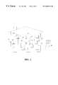
- FIG. 1is a semi-schematic view of a personal shopping system employing the portable terminal of the present invention
- FIG. 2is an alternative embodiment of a home portion of the system of FIG. 1;
- FIG. 3Ais a front elevational view of a first embodiment of portable terminal of the present invention.
- FIG. 3Bis a side semi-schematic cross-sectional view of the portable terminal of FIG. 3A;
- FIG. 4is a semi-schematic plan view showing use of the portable terminal in a shopping establishment
- FIG. 5Ais a first embodiment of home cradle for use with the first embodiment of portable terminal of the present invention
- FIG. 5Bis a second embodiment of home cradle for use with the first embodiment of portable terminal of the present invention.
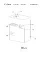
- FIG. 6is a perspective view of a shopping establishment kiosk cradle of the present invention.
- FIG. 7is a side semi-schematic cross-sectional view of a second embodiment of portable terminal of the present invention.
- FIG. 8Ais a third embodiment of home cradle for use with the second embodiment of portable terminal of the present invention.
- FIG. 8Bis a fourth embodiment of home cradle for use with the second embodiment of portable terminal of the present invention.
- FIG. 9Ais similar to FIG. 3A but depicts a third embodiment of the portable terminal of the present invention.
- FIG. 9Bis similar to FIG. 3B but also depicts the third embodiment of portable terminal of the present invention.
- FIG. 10is a fourth embodiment of the portable terminal of the present invention.
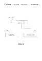
- FIG. 11is a block diagram showing a first embodiment of a portable terminal hardware architecture in accordance with the present invention.
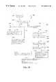
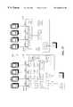
- FIG. 12is a block diagram showing in detail the hardware architecture of FIG. 11;
- FIG. 13is a block diagram showing a second embodiment of a portable terminal hardware architecture in accordance with the present invention.
- FIG. 14is a block diagram showing in detail the hardware architecture of FIG. 13;
- FIG. 15is a front view of a preferred embodiment of a stackable cradle assembly of the present invention.
- FIG. 16illustrates the docking of a portable terminal with the stackable cradle of FIG. 15;
- FIG. 17is a rear view of the stackable cradle assembly of FIG. 15;
- FIG. 18illustrates a two-cradle configuration in accordance with the stackable cradle embodiment of FIG. 15;
- FIG. 19illustrates a three-cradle configuration in accordance with the stackable cradle embodiment of FIG. 15;
- FIG. 20illustrates an eight-cradle configuration in accordance with the stackable cradle embodiment of FIG. 15;
- FIG. 21is a circuit schematic for a 4-slot serial cradle according to a preferred embodiment of FIG. 15;
- FIG. 22shows the firmware architecture for the serial cradle of FIG. 21
- FIG. 23is a flow diagram corresponding to the firmware of FIG. 22;
- FIG. 24is a circuit schematic for an Ethernet cradle according to a preferred embodiment of FIG. 15;
- FIG. 25shows the firmware architecture for the Ethernet cradle of FIG. 24 ;
- FIG. 26is a flow diagram corresponding to the firmware of FIG. 25;
- FIG. 27is a circuit schematic for a daisy chained configuration utilizing the 4-slot serial cradle of FIG. 21 and the 4-slot Ethernet cradle of FIG. 24;
- FIG. 28shows the software architecture for a portable terminal diagnostics utility according to the present invention
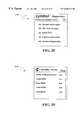
- FIG. 29shows an example of a main diagnostics screen corresponding to the diagnostics utility of FIG. 28;
- FIG. 30shows an example of a screen corresponding to the system information test of FIG. 28;
- FIG. 31shows an example of screens corresponding to the bar code scanner test of FIG. 28;
- FIG. 32shows an example of a screen corresponding to the serial port test of FIG. 28.
- FIG. 33shows a preferred method for powering on a bar scanner motor and corresponding laser source of a portable terminal.
- a personal shopping system 10is suitable for combined used in both a home 12 of a user and at least one shopping establishment 14 .
- the systemincludes a host computer 16 .
- Host computer 16can be located in shopping establishment 14 , or can be otherwise associated therewith; e.g., it can be remotely located therefrom but in communication with other components of the system within shopping establishment 14 .
- the host computer 16could be a grocery or retail store's main computer which is coupled to a set of cash registers; a central site system dedicated for home shopping or shopping generally from locations other than a store's retail facility; or a combination of both. Internet access to host 16 can also be employed.
- System 10also optionally includes at least one wireless multi-access point 18 which is associated with the shopping establishment 14 and which is coupled to the host computer 16 .
- Wireless multi-access point 18if used, would normally be present in or near shopping establishment 14 in order to pick up signals from a portable terminal to be discussed below, when the portable terminal is present within the shopping establishment 14 .
- the systemfurther includes a host modem 20 which can be situated similarly to the host computer and which is coupled to the host computer 16 .
- Host modem 20can in turn be coupled to a public or private telephone line 22 which may be hard-wired, cellular, satellite and the like.
- the systemfurther includes at least one shopping establishment kiosk cradle 24 coupled to the host computer 16 .
- the kiosk cradle 24in turn includes a kiosk portable terminal-receiving station 26 and a kiosk data interface 28 which is associated with the kiosk portable terminal-receiving station 26 .
- associatedit is meant that the kiosk optical interface 28 is located so as to communicate with a two-way data interface of the portable terminal, to be discussed below, when the portable terminal is placed in the portable terminal-receiving station 26 .
- the systemyet further includes a home cradle 30 which is associated with the home 12 of the user.
- a home cradle 30which is associated with the home 12 of the user.
- “associated”would normally imply that the home cradle 30 is located within the home or at some nearby location where it is convenient for the user to use the home cradle without having to separately travel to a shopping establishment 14 .
- Home cradle 30includes a home portable terminal-receiving station 32 and a home data interface 34 which is associated with the home portable terminal-receiving station 32 .
- the data interface 34is so located so as to interface with a corresponding two-way data interface of a portable terminal, to be discussed below, when the portable terminal is placed in the portable terminal-receiving station 32 of the home cradle 30 .
- Home cradle 30still further includes a home data transfer data circuit 36 .
- Transfer circuit 36is coupled to the home data interface 34 so as to engage in data exchange with the optical interface, and is also configured for data exchange with the host modem 20 .
- Such data transfercan occur, for example, through telephone line 38 which can be any of the types discussed above for telephone line 22 .
- a first embodiment of portable terminal 40includes a two-way data interface 42 , such as a laser or CCD bar code reader, which is configured to read bar codes associated with items 44 related to shopping.
- the items 44can be, for example, empty packages of items which it is desired to re-stock; items from a catalog representing goods or services; and the like.
- Portable terminal 40also includes a memory 46 coupled to the two-way data interface 42 for storing data associated with the bar codes from the items 44 .
- Terminal two-way data interface 42is configured for data exchange with the kiosk data interface 28 when the portable terminal 40 is received in the kiosk portable terminal-receiving station 26 .
- Terminal data interface 48is also configured for data exchange with the home data interface 34 when the portable terminal 40 is received in the home portable terminal-receiving station 32 .
- Items 28 , 34 & 44are all depicted schematically by a single rectangle in FIG. 3B; it will be appreciated that they are in fact separate items which are merely illustrated in this fashion for convenience.
- Portable terminal 40can further optionally include a wireless transceiver 50 which is coupled to memory 46 and which is configured for wireless communication with the optional at least one wireless multi-access point 18 when a user of the system takes the portable terminal 40 into the shopping establishment 14 .
- Optional transceiver 50may be provided with a suitable antenna 52 which is compatible with an antenna 54 of wireless multi-access point 18 (as shown in FIG. 1 ).
- the wireless transceiveris either a direct sequencing or frequencing shopping communication scheme working at ranges at or above 900 MHZ.
- a wireless networkis the Spectrum 24TM system sold by Symbol Technologies, Inc., the assignee of the present invention.
- an initialization procedurecan be carried out on terminal 40 when entering a shopping establishment 14 , by swiping a special bar code or otherwise, to set an appropriate frequency for wireless communication and to enter an appropriate code for security and identification purposes.
- home data transfer circuit 36supplies host computer 16 with the data associated with the bar codes of the shopping-related items 44 when the portable terminal 40 is received in the home portable terminal-receiving station 32 .
- Shopping establishment kiosk cradle 24accepts the data associated with the bar codes of the shopping-related items 44 from the portable terminal 40 through the kiosk data interface 28 and the terminal two-way data interface 42 when the portable terminal 40 is received in the kiosk portable terminal-receiving station 26 , and then downloads the data associated with the bar codes of shopping-related items 44 to the host computer 16 .
- Host computer 16receives the data associated with the bar codes of the shopping-related items 44 and stores the data in a shopping list database.
- the system 10can also include at least one point-of-sale checkout terminal 56 associated with the shopping establishment 14 and coupled to the host computer 16 .
- Point-of-sale checkout terminal 56can be employed by a user 58 to pay for purchases made with system 10 (optionally, with assistance from a sales clerk).
- the checkout terminalcould be an automatic payment center for receiving payment, bagging material and removing/detaching electronic surveillance tags, such as RFID tags, magnetic tags or ink tags. The area would also be monitored by camera or an attendant serving multiple registers 56 .
- the portable terminal 40can further include intrinsic identifying indicia (not amenable to further illustration) to identify the bearer to the host computer 16 as an authorized user 58 .
- intrinsic identifying indiciacan include a unique identification code which can be “burned in” to circuitry (e.g., ROM, PROM, EPROM) of the portable terminal 40 or which may be set, for example, by dip switches or stored in a secure manner in RAM or in any other convenient manner.
- Terminal 40can thus function as an “identifying token” or “electronic key.”
- a personal identification number (PIN)can be used instead or as a supplement, for added security (to guard against theft of terminal 40 ).
- terminal 40can be used in conjunction with a credit or debit card of the user and can have identical identifying indicia (and an identical PIN); interface with the magnetic strip reader could be provided for entering credit card information into terminal 40 or directly into host 16 .
- home data transfer circuit 36can simply be a home modem 60 or network adapter which communicates with host modem adapter 20 .
- a suitable telephone jack 62can also be provided.
- Alternative data transfer circuit 36 ′includes an interface card 64 for coupling the home cradle 30 to a separate home personal computer 68 and home modem 70 , which in turn communicate with host modem 20 .
- Card 64can be coupled to home computer 68 through a suitable computer cable connector 66 , for example.
- kiosk data interface 28 and home data interface 34can be any type of suitable interface, for example, optical, electrical plug, radiophone, inductive transfer (such as used in heart rate monitors), and the like, including combinations thereof Optical interfaces are illustrated for convenience.
- any type of suitable interfacecan be employed for two-way data interface 42 of terminal 40 : optical, electrical plugs, radiophone, inductive transfer, and the like.
- a two-way optical interfaceis illustrated in FIGS. 3A and 3B for convenience. In such a system, a stationary laser is normally employed and item 44 must be “swiped.”
- FIGS. 9A and 9Bare similar to FIGS. 3A and 3B except for a different two-way data interface 42 ′′ which is formed by a bar code scanner such as conventional moving laser bar code scanner 1100 , and a separate electrical plug-type connector 1102 (or other interface discussed above) for communication with the other data interfaces of the system, which in this case would also be electrical plug (or other corresponding) types.
- a nominally “one-way” bar code scanner, such as item 1100 , and the plug-type connector 1102 (or other interface)together enable two-way communication and form two-way data interface 42 ′′.
- portable terminal 40can optionally include a display 72 for displaying information to the user and a plurality of control keys for permitting the user to interact with the display 72 .
- the control keyscan include, for example, up and down scroll keys 74 and 76 respectively.
- Hard function keys 78can be included, for example, to call up a calendar, telephone list, shopping list, and notes associated with the shopping list.
- One or more touch keys 80can be provided for purposes of custom applications to allow a soft function approach to interactive program inputs.
- a separate bar code activation button 82can be used to trigger bar code reading while an additional button 84 can be provided to initiate data transfer on docking in either of cradles 24 , 30 .
- a region 86can be provided for purposes of communication via optical character recognition, for example, using the so-called “Graffiti Alphabet” of the Palm Computing Palm Pilot Device.
- Portable terminal 40can also include a speaker 88 for supplying audible messages to the user. Speaker 88 can also beep when a bar code has been successfully read, and can beep a different tone or pattern of tones when scanning has not been successful. Terminal 40 can further include a position-sensing module 90 for sensing the position of the user within the shopping establishment 14 and for communicating with the user via the display 72 (or otherwise) when the user has deviated from an optimal shopping path in the shopping establishment 14 . Module 90 can also be used to alert the customer to specials in their area to alert customers to list items in their area. When speaker 88 is present, the communication with the user can be audibly through speaker 88 . Module 90 can interface, for example, with a GPS or similar system.
- various receiverscan be located throughout shopping establishment 14 to sense the presence of user carrying terminal 40 , as is known in the art of patient monitoring for hospitals. Further details will be provided below regarding the user's path through the shopping establishment, in a discussion of the method of the present invention.
- Terminal 40can include a suitable power source 92 , for example, suitable dry cell batteries. Further, a control module 94 can be provided to drive the display 72 and to control the operation of the various other components of terminal 40 .
- the above-described portable terminal 40can be formed by adding a suitable two-way data interface 42 (and optional buttons 82 , 84 ), as well as other herein-described components, to the well known Palm-Pilot device manufactured by Palm Computing.
- kiosk cradle 24includes kiosk portable terminal-receiving station 26 and kiosk optical interface 28 .
- a printer 96may be provided and can be used to print out a hard copy shopping list 98 in response to information in the shopping list database. Printer 96 can also provide recipes, nutritional information and/or coupons.
- a display 200can also be provided.
- a keyboard 1104can be provided for entering a PIN.
- the present inventioncan comprise the assembly of all the aforementioned components.
- the inventionalso contemplates a home station comprising the above-mentioned home cradle 30 and portable terminal 40 only.
- Home cradle 30would normally remain within the home of the user, while portable terminal 40 is portable between the home and shopping establishment 14 .
- the present inventionalso contemplates the personal shopping system portable terminal 40 by itself.
- the present systemcan be employed with a telephone 100 of a user, having an ordinary touch-tone key pad, and associated with the user's home 12 , for purposes which will be discussed fully below.
- FIGS. 7, 8 A and 8 Ban alternative embodiment of portable terminal 40 ′ in accordance with the present invention will now be described. Items similar to those described above for the first embodiment 40 have received the same reference character but with a “prime” following it; item 36 ′′ corresponds to item 36 and item 36 ′′′ corresponds to item 36 ′.
- Alternative portable terminal 40 ′is generally pen-shaped, and has an elongate pen-shaped housing 201 having an end 203 with an optically transparent passage 205 therethrough.
- the memory 46 ′ and the two-way terminal data interface 42 ′are arranged in the housing 201 with the two-way terminal data interface 42 ′ positioned for communication (preferably optical) through the transparent passage 205 .
- the two-way terminal data interface 42 , 42 ′can include a light emitting diode 207 and a photodetector 209 , employed in a manner well-known in other optical communication systems.
- Other types of data interfaces as discussed abovecan also be used in terminal 40 ′.
- the two-way terminalincludes a laser bar code reader such as the SE-900 available from SymbolTechnologies, Inc.
- the user scanneris less than 0.3 inches wide and includes a scanning laser and a photodetector.
- other “miniaturized” scannerscan be employed depending on the preferred size and economic preferences.
- Alternative embodiment 40 ′can also include a trigger 82 ′ for triggering reading of bar codes located on shopping-related items 44 ′.
- the triggercan be an inductive switch, push button or pressure sensitive pad area. This function can also instead be automatic, e.g., upon “swiping” an item 44 , wherein the swiping can be automatic or user performed.
- a speaker 211or other “beeping” device, can also be provided as above. Note that the kiosk data interface 28 ′, home data interface 34 ′, and shopping-related items with bar codes 44 ′ are all represented by the same rectangle in FIG. 7, as they were above in the first embodiment.
- Alternative embodiment 40 ′can also include a power source 92 ′ and control module 94 ′ as described above.
- the alternative embodiment 40 ′can have diameter of about 3 ⁇ 8 inches and a length of about 5-6 inches to permit convenient carrying and storage by a user, for example, in a pocket or purse like an ordinary pen, and can thus be configured for easy gripping by a user of the system.
- An example of such a penis the “InfoPen” recently available from Symbol Technologies, Inc.
- FIGS. 8A and 8Bare entirely similar to FIGS. 5A and 5B above, except that the portable terminal-receiving station is shaped to receive the alternative embodiment of portable terminal 40 ′. It should be noted that wherever portable terminal 40 is discussed in this application, the discussion also includes alternative embodiment of portable terminal 40 ′. Certain features of portable terminal 40 , such as the display, may not be most conveniently incorporated into portable terminal 40 ′ due to its more compact shape; this will be apparent when reading the appropriate passage in this application.
- Either embodiment of terminal 40 , 40 ′can be combined with a cordless telephone as a convenience and also to use the wireless communication circuitry of the cordless phone for data interface purposes.
- the methodincludes the step of reading bar codes associated with the shopping-related items (i.e., goods and/or services) with a two-way data interface 42 of a portable terminal 40 .
- the methodfurther includes the step of storing data associated with the bar codes in a memory 46 of the portable terminal 40 .
- the methodyet further includes the step of transferring the data associated with the bar codes to a host computer 16 for storage in a shopping list database.
- the transferring stepincludes the sub-steps of transferring the data associated with the bar codes from the memory 46 of the portable terminal 40 to the two-way terminal data interface 42 of the portable terminal 40 ; and then transferring the data associated with the bar codes from the two-way terminal data interface 42 to an data interface of either the kiosk portable terminal-receiving station 26 or the home portable terminal-receiving station 32 ; and then to the host computer.
- the kiosk portable terminal-receiving stationis part of the shopping establishment kiosk cradle 24 which is coupled to the host computer 16 .
- the home portable terminal-receiving stationis part of the home cradle 30 which is associated with the home 12 of the user and is also coupled to the host computer 16 .
- the inventive methodcan include the additional steps of reading a bar code on a shopping-related item 44 which is a special bar code associated with a shopping establishment 14 , using the two-way data interface 42 of the portable terminal 40 .
- home cradle 30can automatically contact the shopping establishment 14 when the portable terminal 40 is placed in the home portable terminal-receiving station 32 of the home cradle 30 . The contacting is done on the basis of information encoded in the bar code associated with the shopping establishment 14 .
- the method of the present inventioncan also include the step of transmitting identifying indicia, for example, intrinsic identifying indicia which may be contained in the terminal 40 , from the portable terminal 40 to the host computer 16 to identify the user to the host computer, as discussed above with respect to the apparatus.
- the methodcan also include the additional step of displaying relevant portions of the shopping list database, discussed above, on the display 72 of the portable terminal 40 .
- host computer 16can send at least one verification query to home cradle 30 in order to verify at least one of correctness and validity of an order which is based on the shopping list database.
- the step of sending the verification querycan include sending the verification query as a human language audible query to the telephone 100 which is coupled to the home cradle 30 . Additionally or alternatively, the step of sending the verification query can include sending the verification query as a signal which triggers visual display of the verification information on display 72 of portable terminal 40 .
- the verification query processcan also include caller identification to prevent theft of goods and/or services.
- the transactioncould be denied.
- the home phonewould normally in turn be associated with the authorized user's home portable terminal-receiving station.
- the usercan be prompted to enter a personal identification number (PIN) to supplement, or in lieu of, identifying indicia in the terminal 40 itself.
- PINpersonal identification number
- the PINcan be entered on the keypad of telephone 100 , separate home PC 68 , or a keypad (not shown) on home cradle 30 .
- a displaycould also be provided on home cradle 30 for use with terminals 40 ′, e.g., which might not have a display.
- the data associated with the bar codesis transferred from the home portable terminal-receiving station 32 , through a suitable interface card 64 , to a separate home personal computer 68 of the user, and then through a home modem 70 to the host computer.
- the methodcan include the additional steps of sending at least one verification query from the host computer 16 to the separate home computer 68 , and then responding to the at least one verification query with at least one response emanating from the separate home computer 68 .
- the home computerincludes a price lookup table, prior shopping lists, recipes including UPC or other scanning data for ordering and other functionality.
- the PCis assumed to have greater memory and peripheral devices such as a CD reader. This would enable a retailer to provide CD or other data files which can provide greater consumer applications and data manipulation prior to transfer to a host.
- the methodcan include the additional step of printing a hard copy shopping list 98 from the kiosk cradle 24 , for example, with printer 96 , in response to the data associated with the bar codes which were read in the home 12 . It will be appreciated that a user of the system can simply check off data items listed on the hard copy shopping list 98 with a conventional ink pen as the items are picked up off the shelves 102 (see FIG.
- the method according to the present inventioncan include the method step of scanning new items required to be purchased, in the shopping establishment 14 , with the portable terminal 40 .
- the scanningcan be in response to the hard copy list, or in response to one or more embodiments of electronic list.
- the methodcan include the additional step of updating the electronic list in the memory 46 of the portable terminal 40 to indicate that a given one of the required new items has been obtained.
- new itemsis meant goods or services in the shopping establishment 14 which are desired by the user of the system. “New” is used to distinguish these items from the (presumably) old items which were scanned at home and which require renewal or replacement.
- a PINcan be entered on keyboard 1104 of kiosk cradle 24 .
- a consumergenerates a list of prepackaged items and downloads the information onto a kiosk. These goods are confirmed for purchase and subsequently collected either in the back room warehouse or by an attendant within the store for pick up by the consumer.
- the consumermay, in the meantime, collect perishable goods which might be subject to product variation, customer preference or simply selective customer shopping, i.e., meats, vegetables, fruits and candies.
- the customerwould be provided a customer order of completion time and location by either a public address system, beeper, or if equipped with a wireless radio, through his or her terminal. The customer would then proceed to a payment register and pay for new items, which could be prescanned with the terminal and automatically downloaded to the register, and previously ordered items.
- Such an ordering processcould also be implemented from home with the proviso that a customer would need to include pickup/drop-off requirements.
- a host or home computergenerates a list of ingredients, i.e., shopping list, according to one or more recipes and downloads the list onto a kiosk and/or a portable terminal. Goods corresponding to the ingredients are confirmed via a portable terminal for purchase and subsequently collected either in the back room warehouse or by an attendant within the store for pick up by the consumer.
- the consumermay also modify the list of ingredients at the portable terminal, for example, to add perishable or seasonable goods which might be subject to price variation, customer preference or simply selective customer shopping, i.e., meats, vegetables, fruits and candies.
- the listcan be further modified by a servings multiplier, which would modify the quantity of certain or all of the ingredients according to anticipated quantities to be served. Again, such an ordering process can also be implemented from a home personal computer.
- a usercan simply periodically re-dock terminal 40 ′ in kiosk 24 to check the updated electronic list, for example, to print a revised list with scanned items “crossed off,” or to view a revised list on optional display 200 of kiosk 24 . If the list is presented it could also include bar codes (or a single high density code) for automatic reprocessing into another kiosk or register.
- Either the hard copy or electronic shopping listcan be produced as an optimized shopping list in response to the shopping list database and information contained in the host computer 16 about location of the items within the shopping establishment 14 .
- the optimized shopping listcan be ordered to direct the user through the shopping establishment 14 in an efficient path. For example, with reference to FIG. 4, user 58 can be directed along the path 104 symbolized by dashed lines so as to move sequentially through shelves 102 of establishment 14 . Items on the shopping list can be printed out in an order in which they will be encountered when user 58 travels efficient path 104 .
- the optimized shopping listcan also offer specials pertaining to items on the list.
- the methodcan include the additional step of sensing the location of the portable terminal 40 with the position-sensing module 90 . This position presumably corresponds to the position of user 58 within the shopping establishment 14 .
- the methodcan include the additional step of communicating a message advising the user 58 when the user 58 has deviated from the efficient path 104 . This message could be generated by wireless communication from host computer 16 to portable terminal 40 , or could be generated otherwise; for example, within terminal 40 in response to downloaded information regarding location of goods. Still referring to FIG.
- a messagecan be sent to the user 58 to indicate that he or she should traverse the one of the shelves 102 which would have been missed in taking inefficient path 106 .
- the listcan be re-optimized with new directions based on the user's new location.
- the communicating stepcan optionally include an audible communication using speaker 88 of portable terminal 40 .
- One of the previously-discussed keys on portable terminal 40can be programmed as an interactive marketing help key to alert shopping establishment personnel to the customer's location.
- Memory 46 and control module 94 of portable terminal 40can be suitably programmed such that memory 46 remembers the one hundred (for example) most frequently purchased products of the user. These one hundred most frequently purchased goods or services (or any other desired number) can be stored in the memory 46 as, for example, a “customer preference file” and can be updated on a continuous basis as the user's preferences change. Further, the user can also have the capability of generating a custom list of frequently-ordered or other desired items. Price and other information associated with the frequent items can be updated, for example, whenever portable terminal 40 is in communication with host computer 16 . Different lists can be maintained for each of a variety of shopping establishments.
- customer preference filescan be uploaded to host 16 at any convenient time, e.g., automatically whenever terminal 40 and host 16 communicate (downloads, to update price (for example) could also be performed at this time). Many of a wide variety of customer preferences could be stored (e.g., vegetarian, health food). Additional details on database management are provided in the aforementioned U.S. patent application Ser. No. 08/866,690 the disclosure of which has been previously incorporated herein by reference.
- the aforementioned verification queriescan include, for example, final price and confirmation of the user's order including price, delivery or pick-up, and desired time. While this information can be sent by voice to telephone 100 , it can instead be sent in written form to display 72 of portable terminal 40 , or to separate home computer 68 , in order to save time for the user.
- the storing step of the methodcan include storing data pertaining to a given shopping establishment, and can include the additional steps of repeating the reading step for items associated with another given shopping establishment, and repeating the storing step for the items associated with the other given shopping establishment, such that multiple lists of item for at least two different shopping establishments are stored in the personal terminal.
- Telephone lines 22 , 38can be employed for dual tone multi frequency (DTMF) communication among any of the components of the system.
- DTMFdual tone multi frequency
- the phone lines 22 , 38can be public or private or a satellite system.
- the usercan scan the bar codes of shopping-related items 44 in home 12 all at one time, or as items are used up and thrown away.
- the consumercan order just the goods scanned, or can edit information in memory 46 of terminal 40 to customize the order.
- Portable terminal 40can then be placed in the portable terminal-receiving station 32 of home cradle 30 .
- a shopping-related item 44 containing a special bar code with information about an establishment from which the order is to be placedcan be scanned.
- Thiscould be a card with a bar code and there could be separate cards for each given shopping establishment, such as the drug store, flower shop, grocery store, auto parts store, etc.
- the card for each of these locationscould also include an identification and/or password.
- the identificationcould also be permanently stored in portable terminal 40 .
- editingcan be carried out with terminal 40 ′ docked in home cradle 30 via interaction with home computer 68 .
- Separate files for each of a number of shopping establishmentscan be created in the memory 46 of portable terminal 40 .
- Memory 46can thus be configured to store multiple lists of data associated with the bar codes, as multiple shopping lists corresponding to multiple shopping establishments. Communication with the appropriate shopping establishment can be indicated by first “swiping” the id card for that shopping establishment. Other files in the memory would not be affected (e.g. florist file not affected by auto parts order).
- the customer cardcould be a credit card which the customer may associate with a single or multiple retailers.
- portable terminal 40is placed in home cradle 30 and cradle 30 then “dials up” the appropriate shopping establishment 14 . At this time, if desired, the user can also pick up the handset of telephone 100 .
- Portable terminal 40can download the entire shopping list to the host computer 16 at once, or can send one item at a time. In the item-by-item mode, the host computer 16 can respond to each item with a digitized voice setting forth the quantity of the item to be ordered and its description and size, and can then prompt the user to, for example, push the pound sign (on the telephone keypad) to confirm or the star sign to enter another number.
- host computer 16can also prompt the user to enter the desired delivery time, complete a survey, and the like via the key pad of telephone 100 . This interaction could also instead be carried out using the display 72 of portable terminal 40 or using the home computer 68 .
- the usercan dock the portable terminal 40 in the kiosk cradle 24 .
- the appropriate shopping list in memory 46is then downloaded and stored in the database in host computer 16 .
- the usercan print the hard copy of the order and check items off with an ink pen as they are scanned with portable terminal 40 and deposited in, for example, a shopping cart of the user.
- the listcan be imported as an electronic list with items automatically checked off as they are scanned, as discussed above.
- the aforementioned optimized shopping listeither in electronic or hard copy form, can be generated. It should be noted that the user can be provided with the option to scan additional items not on the list, for example, in response to impulse purchases and the like.
- the message sent to the usercould be as specific as prompting the user to go back to a given shelf and to remind them which product on that shelf they forgot to purchase or to otherwise delete the item from the list.
- the usercan be “checked out” at one of the point of sale check out terminals 56 in a manner similar to current computer-aided shopping systems. That is, they can present the computerized list and simply tender payment, with occasional auditing to ensure integrity of the system.
- the shopping listcan be up-loaded to terminal 56 and printed.
- the present inventioncan also be employed by store personnel who are picking a home-placed order which is already in the database of host computer 16 .
- An appropriate billing transactioncan then be completed at any point in time by any associate in the shopping establishment 14 , whether it be when the user comes to pick up the order, or before or after the order is shipped to the user.
- FIG. 10shows a fourth embodiment of the portable terminal of the present invention.
- This embodimentis similar to the embodiment of FIG. 9A, but in addition includes two bar code activation buttons 82 disposed on the left and rights of the terminal each for triggering bar code reading by the user.
- two bar code activation buttons 82 disposed on the two sides the terminal housingallow the user to simultaneously view the terminal display while viewing the visible light source upon activation of the bar code scanner.
- FIG. 11shows a high-level block diagram of the hardware architecture for the portable terminal of the present invention.
- the portable terminalincludes a scanning device 910 for reading bar code, a scanner decoder 920 coupled to the scanning device 910 , a communications interface/memory board 930 coupled to the scanner decoder 920 , and a main processing board 940 coupled to the board 930 . Further details of the hardware architecture are described with reference to the detailed architecture 901 shown in FIG. 12 .
- the scanning device 910is used for reading bar code data from any coded product or item, and for generating a corresponding digital bar code pattern.
- the scanning devicecan be any suitable laser or CCD scanner, for example, and is preferably the SE-900 laser scanner available from Symbol Technologies, Inc.
- the scanning deviceoutputs Digital Bar Code Pattern (DBP) and a Start of Scan (SOS) signals to the scanner decoder 920 . Further, the scanning device is activated and configured into various modes of operation in accordance with control data provided by the decoder 920 .
- Typical control datamay include the Laser Enable, Scan Enable and Configuration commands shown in FIG. 12 .
- the scanner decoder 920which interprets the DBP and the SOS data and generates corresponding serial decoded data, is capable of interpreting any number of bar code types, and may be any suitable processor such as the Toshiba 16-bit processor shown in FIG. 12 .
- Right and left trigger buttonssuch as the bar code activation buttons 82 of FIG. 10, are used to generate the necessary control signals to initiate scan by the scanning device 910 .
- Signals indicating the “decode” and “scan” statusare in turn provided so as to illuminate indicator devices such as LED's 993 and 994 .
- Interrupt signal IRQis also provided by the decoder 920 to the communications interface 930 .
- Communications interface 930is used to convert the decoded bar code data for further processing by a microprocessor included in the main processing board 940 .
- the communications interface 930includes an Application Specific Integrated Circuit (ASIC) or gate array 933 that includes a serial-to-parallel converter for converting the serial data stream provided by decoder 920 to parallel data for processing by the microprocessor 941 of the main processing board 940 .
- the ASICincludes a Universal Synchronous Asynchronous Receiver-Transmitter (USART) 934 , an address decoder 935 and a logic device for selecting the interrupt for the USART.
- the communications interface 930further provides an interrupt signal IRQ to the microprocessor 941 and includes ROM, PSRAM or equivalent memory devices for storing a terminal operating system, terminal application programs and related data.
- Microprocessor 941preferably a DragonBall MC68328 microprocessor, is provided for processing the converted decoded bar code data, executing the terminal operating system and terminal applications, e.g., personal organizer/calendar, Internet browser, etc., and generally for controlling the overall operation of the terminal device.
- the microprocessor 941further includes in turn an interface for coupling to a touch sensitive display, which itself includes a backlight 946 , LCD 947 and touch panel 948 .
- One or more interfaces 944are further provided for receiving user-activated function commands, along with a synchronization port 943 for automatically synchronizing the terminal to a host computing device.
- the microprocessor 941also includes an infrared link 942 and interface to a speaker device 945 .
- FIG. 13is a block diagram showing a second embodiment of a portable terminal hardware architecture in accordance with the present invention.
- the embodiment of FIG. 13is a modified version of the embodiment of FIG. 12 wherein a wireless communications device 970 is coupled to the communications interface 930 and a corresponding antenna.
- the communications device 970is the Spectrum 24TM radio, available from Symbol Technologies, Inc., which is coupled via a PCMCIA or equivalent interface 953 included in the ASIC 933 .
- the portable deviceis inserted into a sled (not shown) that mates to the synchronization port 943 .
- FIG. 15shows a perspective view of a stackable cradle assembly 1000 according to a preferred embodiment of the present invention.
- the present embodiment of the cradleis arranged and constructed for docking with one or more of the portable terminals of FIGS. 9A and 9B.
- the cradle 1000 of FIG. 15is stackable and especially adaptable for use in shopping, warehousing, health care, service centers and packaging/trucking establishments.
- the present embodiment of the cradle 100includes one or more docking stations 1002 through 1008 for linking one or more portable terminals to a host computer so that data may be transmitted between the terminals and the host computer.
- the number of docking stations in FIG. 15is shown by way of example and not limitation.
- Each docking station 1002 , 1004 , 1006 and 1008includes a cradle data interface 1012 , 1014 , 1016 and 1018 , and means for supporting the portable terminals 1022 , 1024 , 1026 and 1028 .
- the cradle 1000is constructed of sturdy, high impact plastic material which is molded at station to receive the portable terminals as shown in FIG. 16 .
- the cradle 1000may also include a communications interface board, a power supply interface, visual indicators and wall-mounting means. As shown in FIGS. 18-20, multiple cradles can be stacked, for example to a wall or on a table top or counter, to interconnect many portable terminals to a host computer.
- FIG. 17shows the back side of the cradle 1000 of FIG. 15 with stacking elements 1202 and 1204 attached thereto.
- Each of the stacking elements 1202 and 1204include horizontally facing attachment hooks 1212 and fastening means 1208 and 1210 .
- the stacking elements 1202 and 1204also include vertically facing attachment hooks 1206 for securing an additional cradle as shown in FIG. 18, and attachment slots 1214 for attaching additional stacking elements.
- FIG. 18shows a plurality of cradles 1310 and 1320 stacked on top of each other using stacking elements 1321 and 1322 .
- Each of the stacking elementsinclude horizontally (not shown) and vertically facing attachment hooks 1323 and slots (not shown) and fastening means 1324 and 1325 for interconnecting the upper cradle 1310 and the lower cradle 1320 .
- the two stacking elements 1321 and 1322are attached to the backside of the lower cradle 1320 via the horizontally facing attachment hooks (not shown).
- the upper cradle 1310is then mounted via the vertically facing attachment hooks 1323 disposed on the top side of the stacking elements 1321 and 1322 , thus securing the lower and upper cradles 1310 and 1320 .
- FIG. 19illustrates another multi-cradle configuration 1400 in accordance with the stackable cradle embodiment of FIG. 15 .
- the multi-cradle configuration 1400includes a lower cradle 1430 , a middle cradle 1420 and an upper cradle 1410 .
- a two sets of stacking elements 1421 , 1422 and 1431 , 1432 , 1433 , 1434are connected to the cradles 1410 , 1420 and 1430 via the corresponding attachment hooks, slots and fastening means.
- FIG. 21shows a circuit schematic for a 4-slot serial cradle 1630 according to the preferred embodiment of the cradle shown in FIG. 15 .
- the serial cradle 1630includes a printed circuit board housing a data transfer circuit 1631 .
- the data transfer circuit 1631includes a microprocessor 1632 for managing communications between the a plurality of portable terminals 1612 , 1614 , 1616 , 1618 and a host computer 1646 and other interconnected cradles 1650 , a multiplexer 1636 for serial communications between each of the portable terminals 1612 , 1614 , 1616 , 1618 and the host computer 1646 , and a corresponding shift register 1634 coupled to multiplexer 1636 the for sending status signals from each of the portable terminals 1612 , 1614 , 1616 , 1618 to the microprocessor 1632 .
- the data transfer circuit 1631is power by a DC power supply 1648 and includes provides the appropriate electrical signals to visual indicators 1640 mounted on the cradle 1630 for displaying the operational status for each of the portable terminals connected to the cradle 1630 .
- each docking station of the serial cradle 1630includes a corresponding cradle data interface (not shown in FIG. 21) for providing serial data communications between the portable terminals.
- the cradle data interfaceare RS-232 ports for providing serial communication.
- the multiplexer 1636is thus capable of processing RS-232 control signals, such as Request to Send (CA) and Clear to Send (CB) signals, and routing transmitted data signals to and from the appropriate portable terminals, ie., Transmit Data (BA) and Receive Data (BB).
- the serial cradle 1630further includes a daisy chain port 1620 , e.g., another RS-232 port, for serially connecting one or more additional cradles.
- a daisy chain port 1620e.g., another RS-232 port
- the serial cradle firmwarerecognizes the daisy chain port 1620 as a fifth slot and uses the normal procedures to arbitrate and issue clearance for communications with the host computer 1646 .
- the serial cradle 1630is capable of being a slave cradle to an Ethernet cradle and thus is capable of providing Ethernet connectivity in a round robin fashion to portable terminals inserted into the docking stations of the serial cradle.
- each serial cradle 1630is provided with a plurality of visual indicators 1640 for displaying the operational status of each of the portable terminals connected to the serial cradle.
- the 4-slot serial cradle corresponding to FIG. 21there are four LEDs 1 through 4 corresponding to each terminal slots or docking stations 1602 , 1604 , 1606 and 1608 .
- each of the LED'shas four associated color states: OFF, RED, ORANGE and GREEN.
- REDindicates the presence of a portable terminal, but with no established communication session.
- ORANGE at a 2 Hertz blink cycleindicates that a communication session has been established and is in progress.
- GREENindicates the presence of portable terminal with a completed communication session.
- FIG. 22shows the firmware architecture for the serial cradle of FIG. 21 .
- the firmware 1700which is executed by the microprocessor 1632 , includes a main module 1702 , a terminal detection module 1704 and a synchronization module 1706 .
- the terminal detection module 1704 of FIG. 22is used to determine whether portable terminals are connected to one or more terminal slots of the serial cradle. When a portable terminal is connected, a voltage VCC is sensed from the portable terminal and detected by the module 1704 and associated hardware. The appropriate logic level is then forwarded to the microprocessor 1632 .
- the synchronization module 1710provides means for automatically synchronizing data between the portable terminals and the host computer.
- Automatic terminal synchronizationis performed to synchronize various entries in the portable terminal, such as for example datebook, address book, “to do” lists, memo pad and expense entries, with entries in the host computer. Synchronization is use to manage individual or multiple portable terminals with the host computer, and to automatically backup data from the portable terminal each time synchronize operations are performed. Terminal synchronization can be performed either locally by physically connecting the portable terminal to the corresponding terminal slot, or remotely by via a modem.
- Synchronizationis managed by a synchronization manager, which runs in the background and monitors a communications port of the host computer for a synchronization command from a portable terminal.
- the synchronization commandcan be provided by physically connecting the portable terminal to the corresponding terminal slot, or by user command.
- Synchronization commandsare processed by the host computer on a first in, first out (FIFO) basis.
- FIG. 23is a flow diagram for the serial cradle main module 1702 .
- a check of the docking stationsis performed to determine whether any of the portable terminals are connected there to (Step 1802 ).
- a checkis performed to determine whether a communication session is in progress (Step 184 ). If the session is done, the indicator light is set accordingly and a scan is done of the remaining cradles (Steps 1808 and 1810 ).
- the firmwarechecks to determine whether any other terminals are waiting and if not the microprocessor launches a synchronization operation on that unit and sets the indicator lights appropriately (Steps 1812 through 1820 ).
- the status of a synchronization status linedetermines whether the synchronization is to be performed in a local mode or a remote or “modem” mode. A voltage greater the 0.7 volts on the synchronization status line causes the portable terminal to initiate a remote synchronization. If the synchronization status line is left floating or tied to ground, the portable terminal will initiate a local synchronization.
- the serial cradleis daisy chained to an Ethernet cradle, the Ethernet cradle drives the synchronization status line of all slots and forces synchronization in a remote configuration.
- the serial cradlewill not allow a presently running communication session with a portable terminal to be interrupted. Instead, the serial cradle firmware remembers to establish a communication session with the newly connected portable terminal and executes synchronization thereof after completion of the currently running session.
- each of the terminal slots of the serial cradleare serviced in a round robin fashion.
- An error in synchronization of one portable terminalwill not affect synchronization of other portable terminals.
- FIG. 24shows a circuit schematic for a 4-slot Ethernet-based cradle 1930 according to a preferred embodiment of the present invention. As with the 4-slot serial cradle of FIG. 21, the number of slots shown is not intended to limit the invention in any way.
- the Ethernet cradle 1630which can be adapted for a variety of Ethernet media types including 10BASE-T, 10BASE-F, and 100BASE-T, etc., includes a printed circuit board housing a data transfer circuit 1631 , which includes: an Ethernet controller 1932 , such as an AMD79C961A, for buffering data and processing data packets; a RAM memory device 1934 for temporarily storing packetized data; a programmable memory device 1936 , such as FLASH or EEPROM memory, for storing executable code; a micro-controller 1938 , such as an AMD186, for executing the stored executable code; a plurality of serial data communications devices 1940 , 1942 , 1944 and 1946 (UARTS) corresponding to a plurality of portable terminals 1912 , 1914 , 1916 , 1918 for converting the parallel data provided by the micro-controller 1938 into serial data for transmission to the portable terminals 1912 , 1914 , 1916 , 1918 ; a plurality serial data interfaces 1902 , 1904 ,
- each of the LED'shas six associated color states: OFF, Solid RED, Slow Flash RED, Fast Flash RED, Slow Flash GREEN and GREEN.
- OFFSolid RED
- Slow Flash REDFast Flash RED
- Slow Flash GREENSlow Flash GREEN
- GREENGREEN
- the flashing RED statesboth indicate error conditions with the communications link to the portable terminal: a slow flash RED indicates that communication to the portable terminal did not start, and a fast flash RED indicates that communication did not end.
- a slow flash GREEN at a 2 Hertz blink cycleindicates that a communication session has been established and is in progress with a connected portable terminal.
- a solid GREENindicates the presence of a portable terminal with a completed communication session.
- FIG. 25shows the firmware architecture for the Ethernet-based cradle of FIG. 24 .
- the softwareincludes: an Ether cradle main (ECR) module 2002 ; a synchronization manager module 2004 ; modem emulator modules 2008 through 2010 ; a debound service (DEB) module 2012 ; an LED service (LED) module 2014 ; a timer service (TMR) module 2016 ; a desynchronizer service (DSY) module 2018 ; a monitor (E 86 ) module 2020 ; and a TCP/IP stack (EBSNET) module 2022 .
- ECREther cradle main
- DEBdebound service
- LEDLED service
- TMRtimer service
- DSYdesynchronizer service
- E 86monitor
- EBSNETTCP/IP stack
- the firmware of FIG. 25allows the Ethernet cradle to act as a router/bridge between Internet Protocol (IP) packets from the Ethernet micro controller and the various serial data interfaces.
- IPInternet Protocol
- the Ethernet cradleprovides IP NAT translation between the IP address of each serial data interface and the IP address assigned to the corresponding portable terminal. This strategy allows the cradle to use the host computer to assign addresses to each serial data interface.
- the terminal's IP addressis used only for the PPP link between the terminal and the Ethernet cradle.
- the IP address assigned by the host computeris used for all network communication.
- the Ethernet cradle firmwareallows the cradle to “fake out” a portable terminal into believing that it is attached to a modem in a dial-up network.
- the Ethernet cradleUpon detecting a new portable terminal being inserted into a slot, the Ethernet cradle automatically initiates a “modem: synchronization operation. The portable terminal then attempts to dial a host. The Ethernet cradle thus emulates a modem, responding to the AT dialing commands as required. Since no real phone system is involved, the “dialing” and “connection” phases are instantaneous.
- the Ethernet cradle“bridges” the link between itself and the portable terminal by moving the data to Ethernet queues for transmission across the network. As part of the bridging, the cradle translates the IP address from that used on the PPP link to the host computer assigned link for the slot.
- the ECR routine 2002is responsible for initializing the cradle hardware, and creating and activating all subordinate hardware and software components and starting the main event processing.
- the ECR routine 2002further collects IP addresses from the host server, maintains PPP links and outputs debug information to the expansion port. If requested, the ECR routine 2002 can also process packet data for the synchronization manager module 2004 .
- the synchronization manager module 2004is used for initializing synchronization operations for portable terminals connected to the Ethernet cradle.
- the synchronization operationsare described above in more detail with reference to the serial cradle embodiment of FIG. 21 .
- Module 2004is responsible for all functions relating to starting, stopping, and tracking synchronization operations related to the portable terminals inserted in the local or expansion cradle slots. These functions include controlling the status LEDs, implementing watchdog timeouts on the starting and finishing of the synchronization operations, and restarting the synchronization routine on all slots and the expansion port if requested.
- Modem emulation modulesinclude a modem emulator lexical analyzer (MO_LEX) module 2008 and a modem emulator UART-based auto-baud (MO-MUA) module 2010 .
- the modem emulation modulesallow the portable terminals to establish PPP connections through a modem with a remote Internet Service Provider (ISP).
- ISPInternet Service Provider
- the cradletakes the place of the ISP, forwarding IP packets received on the PPP connection to the Ethernet and via the Ethernet to the Internet, and vice versa. With such a link, the portable terminals then establish a TCP/IP connection with the host computer, and synchronization operations are performed over the link.
- the MO_MOE module 2006emulates a Hayes compatible modem long enough to recognize the baud rate of the portable terminals and to provide a CONNECT ⁇ BAUD> message to the portable terminal so that a PPP session can begin.
- the MO_LEX module 2008tokenizes the stream of modem setup and dial commands sent through the serial data interfaces by the portable terminals.
- the MO-MUA module 2010automatically detects that baud rate at which the portable terminals are communicating.
- the DEB module 2012provides generic debounce service: for each debounce entry registered, this module will accept jittery UP and DOWN events and give callback with debounced UP and DOWN events to the registered owner of the debounce entry.
- the LED module 2014provides a generic 4-color (counting OFF) LED service. This service handles all LED logic including setting the color or turning the LEDs OFF, and allows setting 3 possible duty cycles, e.g., solid color, fast flash, and slow flash.
- the TMR module 2016is a generic timer service that provides users with either one-shot or periodic timers. When the timer times out, a callback is generated to the timer owner. This module service also multiplexes single timers into several timers wherein the resolution of the multiplexed timers is approximately 0.5 msec.
- the DSY module 2018is a generic event queue. However, it has been specialized to register an event dispatch task with the EBSNET stack. So, all events posted to it will eventually result in a dispatch via a callback to the component that posted the event. These messages are dispatched at application idle time.
- the E86 module 2020is a monitor that accepts downloads of new firmware for the cradle, including if necessary, upgrading the E86 module itself
- the modulemonitors the expansion port of the cradle and is accessible for about three seconds after power-up.
- This modulecan also be used to configure the Ethernet cradle to run in diagnostic mode. In diagnostic mode, operation of the cradle proceeds normally, except that the expansion port is utilized to give diagnostic messages to a host PC, rather than as a data link to the serial chain.
- the EBSNET module 2022implements Ethernet and serial TCP/IP communication. The module also recognizes events from the UART and the modem emulator module.
- FIG. 26is a flow diagram for the Ethernet cradle main module 2002 .
- the ECR module 2002issues instructions to start the cradle LEDs flashing a power-up sequence (Step 2102 ).
- the ECR module 2002then waits for a character input at the expansion port, or performs a three second timeout if none is present (Step 2104 ). All cradle LEDs are then turned off. (Step 2106 ). If an “a” character is detected at the cradle expansion port, the E86 monitor module is executed (Step 2110 ). If a “d” character is detected, all permanent registers of the cradle are set to diagnostics mode (Step 2114 ). If the ECR module 2002 performs a three second timeout, then the permanent registers are set to normal mode (Step 2112 ).
- the ECR module 2002then initializes the RTIP protocol stack and attempts to collect IP addresses corresponding to the cradle slots from the host server (Steps 2116 and 2118 ). If a server is present in accordance with Step 2120 , then all IP addresses registered with the server are collected (Step 2122 ). If no server is present, then private IP addresses are assigned to the local slots and to the logical slot that represents the serial chain (Step 2128 ). Note, Step 2128 is executed only for debugging purposes, and is not intended for general use in that the privately assigned addresses may conflict with other private IP addresses.
- Step 2130if enough IP addresses are available for all slots of the cradle, then the ECR module initializes and parameterizes the service modules shown in FIG. 25 (Step 2130 ). All UART events are then cleared (Step 2132 ), and PPP services are started on each slot (Step 2134 ). The synchronization manager module is that initialized, parameterized and activated (Step 2136 ), and the UART driver generates events for all portable terminals (Step 2138 ). If according to Step 2124 there are not enough IP addresses, all collected IP addresses are relinquished and processing continues according to Step 2128 .
- FIG. 27shows another preferred embodiment of the present invention wherein the 4-slot serial cradle 1630 of FIG. 21 is daisy chained to the 4-slot Ethernet-based cradle 1930 of FIG. 24 .
- the 4-slot serial cradle 1630 of FIG. 21is daisy chained to the 4-slot Ethernet-based cradle 1930 of FIG. 24 .
- simultaneous data communicationsis possible with five portable terminals at any given moment, i.e., the four Ethernet terminals and one of the serial terminals.
- the aforedescribed embodiments of the present inventionalso feature a diagnostics utility in each of the portable terminals for ensuring that the portable terminals are operating properly and to assist in troubleshooting if necessary.
- the diagnostics utilitytests the various features of the portable terminals, and reports to the user whether or not the terminal features are functioning properly.
- FIG. 28shows the software architecture for the portable terminal diagnostics utility.
- the portable terminal diagnostics utility 2300includes a main module 2302 , a system information test module 2304 , a bar code scanner test module 2306 , a serial port test module 2308 , a digitizer alignment test module 2310 , and a system diagnostics test module 2312 .
- the diagnostics utility of FIG. 27is implemented in software and stored in ROM in the each of the portable terminals.
- Corresponding graphical user interfaces, as shown in FIGS. 29-32are also provided for executing the various tests. As shown, the diagnostics screens are written using the Satellite FormsTM software development tool.
- FIG. 29shows an example of a main diagnostics screen 2400 corresponding to the diagnostics utility of FIG. 28 .
- the main diagnostics screen 2400displays the above-referenced test module options to the user. Further selection of the displayed options generates the appropriate display of related information.
- FIG. 30shows an example of a screen 2500 corresponding to the system information test 2304 of FIG. 28 .
- the system information testis used to describe the attributes of the portable terminal, and is used along with the display screen 2500 to report information including but not limited to the following information about the portable terminals: name of manufacturer, the total amount of RAM, the amount of available or free RAM, the amount of ROM, the user name of the terminal, running version of the operating system and the voltage level or charge status of the batteries.
- FIG. 31shows an example of screens corresponding to the bar code scanner test 2306 of FIG. 28 .
- the bar code scanner testverifies proper operation of the integrated scanner in the portable terminal, and the associated screens allow for the selection of bar code and label types.
- FIG. 32shows an example of a screen 2700 corresponding to the serial port test module of FIG. 28 .
- the serial port testis used to test the portable terminal's serial port by sending a test message. Test configuration and results are then displayed on screen 2700 .
- the digitizer alignment testis used to test the tracking of a stylus or comparable pointing device on the portable terminal display screen. To run this test, the pointing device is contacted in various places on the display screen and crosshairs appear under the pointing device. The crosshairs are then used to track the motion of the pointing device on the display screen.
- the systems diagnostics testis an interactive test of all the terminal's system features. This test prompts the user to perform certain steps, which are verified via visual or audio indications and recorded in a systems diagnostic log.
- a preferred embodiment of the present inventionincludes a bar code scanner such as conventional moving laser bar code scanner.
- a laser scannerincludes a laser source and a motor device, which typically produces a large power surge if the laser source and motor device are simultaneously powered ON.
- the present inventionalso includes a method for minimizing power consumption of the power terminal by first powering the scanner motor and then the scanner laser source.
- FIG. 33shows a preferred method for powering on a bar scanner motor and corresponding laser source of a portable terminal according to the present invention.
- the methodincludes the steps of: activating the bar scanner motor (Step 2802 ); sampling the battery voltage V B of the portable terminal (Step 2804 ); comparing the battery voltage V B to a threshold battery voltage V TH (Step 2806 ); and activating the laser source if the battery voltage exceeds the threshold battery voltage V TH (Step 2808 ).
- the methodfurther includes the steps of: sampling the battery voltage a plurality of times (Step 2810 ); storing readings corresponding to said plurality of sampling steps (Step 2812 ); determining whether a majority of the readings exceed the battery voltage threshold (Step 2814 ); and activating the laser source when a majority of the readings exceed the battery voltage threshold (Step 2816 ).
- the above-described power management schememay be critical in certain applications wherein data stored in the portable terminals would be difficult to reproduce.
- the above schemethus ensures that the voltage is not drained to a point where the battery will no longer service the volatile memory addresses. Accordingly, prior to undertaking a procedure requiring relatively high battery usage, the battery voltage level can also be checked. The user is then notified of low battery power if the level is insufficient to complete the initialized action.
- the motor for the mirror, LED and photodetectorcould be powered in a staggered manner, i.e., not simultaneously.
- the terminal of the present inventionfurther provides several other ergonomic advantages.
- keys 82are provided at the top of the terminal in both the right and left sides of the terminal such that the terminal can be used by both left and right handed individuals.
- the keys 82are also designed to activate by applying pressure to either the top or side of the keys.
- the translationsare converted internally by guides and springs to active buttons notwithstanding the direction of the pressure applied.
- the laser scanneris designed to release a visible light from the top of the terminal so that it is evident to the user what is being scanned by the terminal bar code reader.
- the terminalrests comfortably in the hands of the consumer and both the screen and laser light coming out of the terminal should be clearly visible to the consumer upon undertaking a scanning action.
- the laser scannermay also share a window with a IRDA port on the terminal thereby reducing component requirements.
- the terminalprovides an improved economic and functional design which is intuitive in usage and feasible for extended usage in commercial environments.
Landscapes
- Business, Economics & Management (AREA)
- Accounting & Taxation (AREA)
- Engineering & Computer Science (AREA)
- Finance (AREA)
- Physics & Mathematics (AREA)
- General Physics & Mathematics (AREA)
- Theoretical Computer Science (AREA)
- Economics (AREA)
- Strategic Management (AREA)
- General Business, Economics & Management (AREA)
- Marketing (AREA)
- Development Economics (AREA)
- Entrepreneurship & Innovation (AREA)
- Human Resources & Organizations (AREA)
- Operations Research (AREA)
- Quality & Reliability (AREA)
- Tourism & Hospitality (AREA)
- Microelectronics & Electronic Packaging (AREA)
- Computer Networks & Wireless Communication (AREA)
- Cash Registers Or Receiving Machines (AREA)
- Mobile Radio Communication Systems (AREA)
Abstract
Description
Claims (67)
Priority Applications (3)
| Application Number | Priority Date | Filing Date | Title |
|---|---|---|---|
| US09/232,142US6640214B1 (en) | 1999-01-16 | 1999-01-16 | Portable electronic terminal and data processing system |
| US09/490,529US7010501B1 (en) | 1998-05-29 | 2000-01-25 | Personal shopping system |
| US10/137,922US7171378B2 (en) | 1998-05-29 | 2002-05-02 | Portable electronic terminal and data processing system |
Applications Claiming Priority (1)
| Application Number | Priority Date | Filing Date | Title |
|---|---|---|---|
| US09/232,142US6640214B1 (en) | 1999-01-16 | 1999-01-16 | Portable electronic terminal and data processing system |
Related Parent Applications (1)
| Application Number | Title | Priority Date | Filing Date |
|---|---|---|---|
| US09/087,086Continuation-In-PartUS6101483A (en) | 1998-05-29 | 1998-05-29 | Personal shopping system portable terminal |
Related Child Applications (2)
| Application Number | Title | Priority Date | Filing Date |
|---|---|---|---|
| US09/490,529Continuation-In-PartUS7010501B1 (en) | 1998-05-29 | 2000-01-25 | Personal shopping system |
| US10/137,922ContinuationUS7171378B2 (en) | 1998-05-29 | 2002-05-02 | Portable electronic terminal and data processing system |
Publications (1)
| Publication Number | Publication Date |
|---|---|
| US6640214B1true US6640214B1 (en) | 2003-10-28 |
Family
ID=29250235
Family Applications (2)
| Application Number | Title | Priority Date | Filing Date |
|---|---|---|---|
| US09/232,142Expired - LifetimeUS6640214B1 (en) | 1998-05-29 | 1999-01-16 | Portable electronic terminal and data processing system |
| US10/137,922Expired - Fee RelatedUS7171378B2 (en) | 1998-05-29 | 2002-05-02 | Portable electronic terminal and data processing system |
Family Applications After (1)
| Application Number | Title | Priority Date | Filing Date |
|---|---|---|---|
| US10/137,922Expired - Fee RelatedUS7171378B2 (en) | 1998-05-29 | 2002-05-02 | Portable electronic terminal and data processing system |
Country Status (1)
| Country | Link |
|---|---|
| US (2) | US6640214B1 (en) |
Cited By (80)
| Publication number | Priority date | Publication date | Assignee | Title |
|---|---|---|---|---|
| US20020002504A1 (en)* | 2000-05-05 | 2002-01-03 | Andrew Engel | Mobile shopping assistant system and device |
| US20020003166A1 (en)* | 1999-04-22 | 2002-01-10 | Miller Michael Robert | System, method and article of manufacture for recipe and/or ingredient selection based on a user-input bar code |
| US20020016739A1 (en)* | 1999-09-21 | 2002-02-07 | Fujitsu Limited | System and method for managing expiration-dated products utilizing an electronic receipt |
| US20020042722A1 (en)* | 2000-10-11 | 2002-04-11 | Takashi Tsuji | Settlement system, settlement program, settlement method, order placing device and information providing device |
| US20020059266A1 (en)* | 2000-04-11 | 2002-05-16 | I'anson Colin | Shopping assistance method and apparatus |
| US20020069114A1 (en)* | 2000-12-01 | 2002-06-06 | Charette Phillip Carl | Method and system for placing a purchase order over a communications network |
| US20020078363A1 (en)* | 2000-03-24 | 2002-06-20 | Hill Richard A. | Apparatus and method for gathering and utilizing data |
| US20020112041A1 (en)* | 2001-02-09 | 2002-08-15 | Brian Viscount | Method and system for servicing a wireless data collection device |
| US20020120519A1 (en)* | 2000-05-23 | 2002-08-29 | Martin Jeffrey W. | Distributed information methods and systems used to collect and correlate user information and preferences with products and services |
| US20020131444A1 (en)* | 2001-03-13 | 2002-09-19 | Moodie Justin Charles | Communications system with database management |
| US20030011681A1 (en)* | 1999-05-28 | 2003-01-16 | Nikon Corporation | Digital image storage and digital image storage system |
| US20030016844A1 (en)* | 2001-06-27 | 2003-01-23 | Chisato Numaoka | Image composition system and method thereof, image generation apparatus and method thereof, storage medium and computer program for image composition |
| US20030061113A1 (en)* | 1998-05-29 | 2003-03-27 | Adam Petrovich | Portable electronic terminal and data processing system |
| US20040002925A1 (en)* | 2002-06-26 | 2004-01-01 | Pitney Bowes Inc. | System and method for optimizing postal rates and discounts |
| US20040004117A1 (en)* | 2001-03-14 | 2004-01-08 | Hitachi, Ltd. | Method and system to prevent fraudulent payment in credit/debit card transactions, and terminals therefor |
| US20040103033A1 (en)* | 2002-11-21 | 2004-05-27 | Kimberly-Clark Worldwide, Inc. | RFID system and method for vending machine control |
| US20040100359A1 (en)* | 2002-11-21 | 2004-05-27 | Kimberly-Clark Worldwide, Inc. | Jamming device against RFID smart tag systems |
| US20040103043A1 (en)* | 2002-11-21 | 2004-05-27 | Kimberly-Clark Worldwide, Inc. | RFID system and method for ensuring food safety |
| US20040103034A1 (en)* | 2002-11-21 | 2004-05-27 | Kimberly-Clark Worldwide, Inc. | RFID system and method for purchase item accountability |
| US20040128210A1 (en)* | 1999-12-28 | 2004-07-01 | Iceberg International, Inc. | Marketing information system for remote computing platforms |
| US20040167851A1 (en)* | 2003-02-21 | 2004-08-26 | W. Jeffrey Knowles | System and method of electronic data transaction processing |
| US20040167854A1 (en)* | 2003-02-21 | 2004-08-26 | Knowles W. Jeffrey | System and method of currency conversion in financial transaction process |
| US20040262391A1 (en)* | 2003-06-26 | 2004-12-30 | International Business Machines Corporation | Apparatus, method, and system for positively identifying an item |
| US20050001030A1 (en)* | 2001-05-04 | 2005-01-06 | Allen Marc L. | Method and system for information display using a multimedia device employing a powerline modem |
| US20050060242A1 (en)* | 2003-09-12 | 2005-03-17 | International Business Machines Corporation | Optimal method, system, and storage medium for resolving demand and supply imbalances |
| US20050071083A1 (en)* | 2003-09-29 | 2005-03-31 | International Business Machines Corporation | Method and structure for monitoring moving objects |
| US20050071321A1 (en)* | 2003-09-29 | 2005-03-31 | International Business Machines Corporation | System and method for monitoring events against continual range queries |
| US20050149414A1 (en)* | 2003-12-30 | 2005-07-07 | Kimberly-Clark Worldwide, Inc. | RFID system and method for managing out-of-stock items |
| US20050149391A1 (en)* | 2003-12-30 | 2005-07-07 | Kimberly-Clark Worldwide, Inc. | RF-based electronic system and method for automatic cross-marketing promotional offers and check-outs |
| US20050148828A1 (en)* | 2003-12-30 | 2005-07-07 | Kimberly-Clark Worldwide, Inc. | RFID system and method for tracking environmental data |
| US20050261981A1 (en)* | 2004-05-24 | 2005-11-24 | Geoffrey Girdler | Point of sale systems and methods |
| US20050285740A1 (en)* | 2004-03-17 | 2005-12-29 | Uwe Kubach | Proximity sensing |
| AU784351B2 (en)* | 2000-02-09 | 2006-03-16 | Symbol Technologies, Inc. | Portable electronic terminal and data processing system |
| US20060074763A1 (en)* | 2004-09-27 | 2006-04-06 | Matthew Schmid | Culinary display kiosk |
| US20060077645A1 (en)* | 2004-10-12 | 2006-04-13 | Mstar Semiconductor, Inc. | Method and device for integrating LCD monitor circuitry |
| US20060091203A1 (en)* | 2001-05-04 | 2006-05-04 | Anton Bakker | Systems and methods for the identification and presenting of information |
| WO2005104730A3 (en)* | 2004-04-28 | 2007-04-26 | Motorola Inc | Item of interest marking and posting system and method |
| US7233920B1 (en)* | 2000-09-07 | 2007-06-19 | Paymentech, L.P. | System and apparatus for credit transaction data transmission |
| US20070235525A1 (en)* | 2006-04-07 | 2007-10-11 | Nearnet Llc | Information accessing and conveying systems and methods |
| US20070276737A1 (en)* | 1999-09-17 | 2007-11-29 | Joao Raymond A | Apparatus and method for providing and/or for fulfilling subscription services |
| US20070284440A1 (en)* | 2006-06-09 | 2007-12-13 | Container Store | Computer supported retail shopping systems and methods |
| US20080103913A1 (en)* | 2006-10-26 | 2008-05-01 | Circuit City Stores Inc. | System and method for guided sales |
| US20080114634A1 (en)* | 2006-11-13 | 2008-05-15 | International Business Machines Corporation | Method, system, and computer program product for determining availability and order scheduling of diverse products and services |
| US20080133264A1 (en)* | 2001-08-14 | 2008-06-05 | Ikan Technologies, Inc. | Networked waste processing apparatus |
| US20080147529A1 (en)* | 2006-12-19 | 2008-06-19 | Bellsouth Intellectual Property Corporation | Surgical suite radio frequency identification methods and systems |
| US20080177899A1 (en)* | 2003-09-12 | 2008-07-24 | Logic Controls, Inc. | Hybrid Industrial Networked Computer System |
| US20080223928A1 (en)* | 2001-08-14 | 2008-09-18 | Ikan Technologies, Inc. | Networked disposal and sample provisioning apparatus |
| US20080250122A1 (en)* | 2006-11-06 | 2008-10-09 | Ikan Technologies, Inc. | Methods and systems for network configuration |
| US20090077131A1 (en)* | 2003-02-21 | 2009-03-19 | Mtrex, Inc. | System and Method of Transferring Data Through Transaction Process |
| US20090076935A1 (en)* | 2003-07-29 | 2009-03-19 | Mtrex, Inc. | System and Method of Account Reconciliation for Electronic Transactions |
| US20090076876A1 (en)* | 2003-02-21 | 2009-03-19 | Mtrex, Inc. | Method of Scheduling and Event Processing in Computer Operating System |
| US20090182641A1 (en)* | 2004-09-16 | 2009-07-16 | Target Brands, Inc. | Financial transaction approval system and method |
| US20090216675A1 (en)* | 2008-02-21 | 2009-08-27 | The Coca-Cola Company | Commission Centric Network Operation Systems and Methods |
| US20090216666A1 (en)* | 2008-02-21 | 2009-08-27 | The Coca-Cola Company | Systems and Methods for Providing Electronic Transaction Auditing and Accountability |
| US20090216575A1 (en)* | 2008-02-21 | 2009-08-27 | The Coca-Cola Company | Systems and Methods for Providing a Vending Network |
| US20090216665A1 (en)* | 2008-02-21 | 2009-08-27 | The Coca-Cola Company | Systems and Methods for Providing Vending Network Data Management |
| US20090222301A1 (en)* | 2008-03-03 | 2009-09-03 | Th Coca-Cola Company | Methods for Implementing a Loyalty Program |
| US20090222340A1 (en)* | 2008-03-03 | 2009-09-03 | The Coca-Cola Company | Systems for Implementing a Loyalty Program |
| US20090222300A1 (en)* | 2008-03-03 | 2009-09-03 | The Coca-Cola Company | Systems and Methods of Marketing to Defined Consumer Groups |
| US20090222339A1 (en)* | 2008-03-03 | 2009-09-03 | The Coca-Cola Company | Systems and Methods for Providing a Personal Terminal for a Loyalty Program |
| US20090248742A1 (en)* | 2008-03-31 | 2009-10-01 | Ebay Inc. | Method and system for mobile publication |
| US7620475B1 (en)* | 2000-06-06 | 2009-11-17 | Datalogic, S.P.A. | Dispensing device of portable terminals for acquiring product data in a shopping centre, integrated system for dispensing said portable terminals, and integrated system for selling products through the use of portable terminals |
| US20090313090A1 (en)* | 2003-09-11 | 2009-12-17 | International Business Machines Corporation | Resolving demand and supply imbalances |
| US7702538B2 (en)* | 2000-08-01 | 2010-04-20 | Jpmorgan Chase Bank, N.A. | System and method for transponder-enabled account transactions |
| US7774243B1 (en)* | 2005-03-11 | 2010-08-10 | Amazon Technologies, Inc. | Method and system for predestination item transfer among agents within a materials handling facility |
| US20100304396A1 (en)* | 1999-10-15 | 2010-12-02 | Dodds W Jean | Animal health diagnostics |
| US7853480B2 (en)* | 2007-05-21 | 2010-12-14 | Amazon Technologies, Inc. | System and method for providing export services to merchants |
| US8296188B2 (en)* | 2008-07-31 | 2012-10-23 | Fujifilm Corporation | Image display system, server apparatus, and terminal apparatus |
| US20140012748A1 (en)* | 2012-07-05 | 2014-01-09 | General Electric Company | Repair system and method |
| USD705792S1 (en) | 2011-12-28 | 2014-05-27 | Target Brands, Inc. | Display screen with graphical user interface |
| USD705790S1 (en) | 2011-12-28 | 2014-05-27 | Target Brands, Inc. | Display screen with graphical user interface |
| US20140144977A1 (en)* | 2012-11-28 | 2014-05-29 | Wal-Mart Stores, Inc. | Scannable recipe card to add items to shopping list |
| US8825660B2 (en) | 2009-03-17 | 2014-09-02 | Ebay Inc. | Image-based indexing in a network-based marketplace |
| USD715818S1 (en)* | 2011-12-28 | 2014-10-21 | Target Brands, Inc. | Display screen with graphical user interface |
| US20170329938A1 (en)* | 2013-01-08 | 2017-11-16 | Bibliotheca Limited | Digital Media Lending System and Method |
| US9821344B2 (en) | 2004-12-10 | 2017-11-21 | Ikan Holdings Llc | Systems and methods for scanning information from storage area contents |
| US20180293831A1 (en)* | 2015-12-15 | 2018-10-11 | Japan Tobacco Inc. | Sales system, sales terminal, user terminal, and program |
| US10102596B2 (en)* | 2010-10-06 | 2018-10-16 | Tillster, Inc. | Customer interface restaurant system |
| US10109026B2 (en) | 2010-10-06 | 2018-10-23 | Tillster, Inc. | Mobile restaurant ordering system |
| US10779731B2 (en) | 2009-08-17 | 2020-09-22 | The Cleveland Clinic Foundation | Method and system for monitoring and managing patient care |
Families Citing this family (172)
| Publication number | Priority date | Publication date | Assignee | Title |
|---|---|---|---|---|
| US7107221B1 (en)* | 1996-09-05 | 2006-09-12 | Symbol Technologies, Inc. | Method and system for presenting item information using a portable data terminal |
| US8225214B2 (en) | 1998-12-18 | 2012-07-17 | Microsoft Corporation | Supplying enhanced computer user's context data |
| US6801223B1 (en)* | 1998-12-18 | 2004-10-05 | Tangis Corporation | Managing interactions between computer users' context models |
| US7779015B2 (en) | 1998-12-18 | 2010-08-17 | Microsoft Corporation | Logging and analyzing context attributes |
| US8181113B2 (en) | 1998-12-18 | 2012-05-15 | Microsoft Corporation | Mediating conflicts in computer users context data |
| US6513046B1 (en) | 1999-12-15 | 2003-01-28 | Tangis Corporation | Storing and recalling information to augment human memories |
| US6791580B1 (en)* | 1998-12-18 | 2004-09-14 | Tangis Corporation | Supplying notifications related to supply and consumption of user context data |
| US9183306B2 (en) | 1998-12-18 | 2015-11-10 | Microsoft Technology Licensing, Llc | Automated selection of appropriate information based on a computer user's context |
| US7231439B1 (en) | 2000-04-02 | 2007-06-12 | Tangis Corporation | Dynamically swapping modules for determining a computer user's context |
| US6842877B2 (en)* | 1998-12-18 | 2005-01-11 | Tangis Corporation | Contextual responses based on automated learning techniques |
| US7046263B1 (en) | 1998-12-18 | 2006-05-16 | Tangis Corporation | Requesting computer user's context data |
| US7225229B1 (en) | 1998-12-18 | 2007-05-29 | Tangis Corporation | Automated pushing of computer user's context data to clients |
| US6920616B1 (en) | 1998-12-18 | 2005-07-19 | Tangis Corporation | Interface for exchanging context data |
| US6434527B1 (en)* | 1999-05-17 | 2002-08-13 | Microsoft Corporation | Signalling and controlling the status of an automatic speech recognition system for use in handsfree conversational dialogue |
| US7103806B1 (en) | 1999-06-04 | 2006-09-05 | Microsoft Corporation | System for performing context-sensitive decisions about ideal communication modalities considering information about channel reliability |
| US6714967B1 (en)* | 1999-07-30 | 2004-03-30 | Microsoft Corporation | Integration of a computer-based message priority system with mobile electronic devices |
| US6622160B1 (en)* | 1999-07-30 | 2003-09-16 | Microsoft Corporation | Methods for routing items for communications based on a measure of criticality |
| US7194681B1 (en) | 1999-07-30 | 2007-03-20 | Microsoft Corporation | Method for automatically assigning priorities to documents and messages |
| US7979309B1 (en)* | 1999-09-15 | 2011-07-12 | Comcast Mo Group, Inc. | Method and system for automating inventory management of consumer items |
| US7231380B1 (en) | 1999-10-09 | 2007-06-12 | Innovaport Llc | Apparatus and method for providing products location information to customers in a store |
| WO2001045008A1 (en) | 1999-12-16 | 2001-06-21 | Debit.Net, Inc. | Secure networked transaction system |
| US7342496B2 (en)* | 2000-01-24 | 2008-03-11 | Nextreme Llc | RF-enabled pallet |
| US8077040B2 (en) | 2000-01-24 | 2011-12-13 | Nextreme, Llc | RF-enabled pallet |
| US7743340B2 (en)* | 2000-03-16 | 2010-06-22 | Microsoft Corporation | Positioning and rendering notification heralds based on user's focus of attention and activity |
| US6847924B1 (en)* | 2000-06-19 | 2005-01-25 | Ncr Corporation | Method and system for aggregating data distribution models |
| US7444383B2 (en)* | 2000-06-17 | 2008-10-28 | Microsoft Corporation | Bounded-deferral policies for guiding the timing of alerting, interaction and communications using local sensory information |
| US8024415B2 (en)* | 2001-03-16 | 2011-09-20 | Microsoft Corporation | Priorities generation and management |
| US20020087649A1 (en)* | 2000-03-16 | 2002-07-04 | Horvitz Eric J. | Bounded-deferral policies for reducing the disruptiveness of notifications |
| US7634528B2 (en)* | 2000-03-16 | 2009-12-15 | Microsoft Corporation | Harnessing information about the timing of a user's client-server interactions to enhance messaging and collaboration services |
| US7464153B1 (en)* | 2000-04-02 | 2008-12-09 | Microsoft Corporation | Generating and supplying user context data |
| WO2001075676A2 (en)* | 2000-04-02 | 2001-10-11 | Tangis Corporation | Soliciting information based on a computer user's context |
| US8086672B2 (en)* | 2000-06-17 | 2011-12-27 | Microsoft Corporation | When-free messaging |
| US9684893B2 (en) | 2000-06-30 | 2017-06-20 | Tara Chand Singhal | Apparatus and method for a wireless point of sale terminal |
| JP2002189933A (en)* | 2000-10-10 | 2002-07-05 | Sharp Corp | Related information providing system for specific electronic information |
| GB2386724A (en)* | 2000-10-16 | 2003-09-24 | Tangis Corp | Dynamically determining appropriate computer interfaces |
| US20020054130A1 (en)* | 2000-10-16 | 2002-05-09 | Abbott Kenneth H. | Dynamically displaying current status of tasks |
| US7844666B2 (en)* | 2000-12-12 | 2010-11-30 | Microsoft Corporation | Controls and displays for acquiring preferences, inspecting behavior, and guiding the learning and decision policies of an adaptive communications prioritization and routing system |
| US7599855B2 (en)* | 2001-02-13 | 2009-10-06 | Lester Sussman | System and method for a complete and convenient shopping experience |
| US6988132B2 (en)* | 2001-03-15 | 2006-01-17 | Microsoft Corporation | System and method for identifying and establishing preferred modalities or channels for communications based on participants' preferences and contexts |
| US7330895B1 (en)* | 2001-03-15 | 2008-02-12 | Microsoft Corporation | Representation, decision models, and user interface for encoding managing preferences, and performing automated decision making about the timing and modalities of interpersonal communications |
| US7689521B2 (en)* | 2001-06-28 | 2010-03-30 | Microsoft Corporation | Continuous time bayesian network models for predicting users' presence, activities, and component usage |
| US7233933B2 (en)* | 2001-06-28 | 2007-06-19 | Microsoft Corporation | Methods and architecture for cross-device activity monitoring, reasoning, and visualization for providing status and forecasts of a users' presence and availability |
| US7409335B1 (en) | 2001-06-29 | 2008-08-05 | Microsoft Corporation | Inferring informational goals and preferred level of detail of answers based on application being employed by the user |
| US7644144B1 (en) | 2001-12-21 | 2010-01-05 | Microsoft Corporation | Methods, tools, and interfaces for the dynamic assignment of people to groups to enable enhanced communication and collaboration |
| US7069259B2 (en)* | 2002-06-28 | 2006-06-27 | Microsoft Corporation | Multi-attribute specification of preferences about people, priorities and privacy for guiding messaging and communications |
| US7870240B1 (en) | 2002-06-28 | 2011-01-11 | Microsoft Corporation | Metadata schema for interpersonal communications management systems |
| US7086995B2 (en)* | 2002-07-26 | 2006-08-08 | Unisen, Inc. | Control circuit using toggled activation to reduce inrush currents |
| US7618345B2 (en)* | 2002-07-26 | 2009-11-17 | Unisen, Inc. | Exercise equipment with universal PDA cradle |
| US20040133772A1 (en)* | 2003-01-07 | 2004-07-08 | Battelle Memorial Institute | Firewall apparatus and method for voice over internet protocol |
| US20040138986A1 (en)* | 2003-01-09 | 2004-07-15 | Adam Petrovich | System and method for multi-channel retail auction |
| US7382277B2 (en) | 2003-02-12 | 2008-06-03 | Edward D. Ioli Trust | System for tracking suspicious vehicular activity |
| US20040181467A1 (en)* | 2003-03-14 | 2004-09-16 | Samir Raiyani | Multi-modal warehouse applications |
| US7457879B2 (en)* | 2003-04-01 | 2008-11-25 | Microsoft Corporation | Notification platform architecture |
| WO2004114131A1 (en)* | 2003-06-24 | 2004-12-29 | Bayerische Motoren Werke Aktiengesellschaft | Method for booting up a software in the boot sector of a programmable read-only memory |
| US8346587B2 (en) | 2003-06-30 | 2013-01-01 | Microsoft Corporation | Models and methods for reducing visual complexity and search effort via ideal information abstraction, hiding, and sequencing |
| US20040264677A1 (en)* | 2003-06-30 | 2004-12-30 | Horvitz Eric J. | Ideal transfer of call handling from automated systems to human operators based on forecasts of automation efficacy and operator load |
| US7738881B2 (en)* | 2003-07-22 | 2010-06-15 | Microsoft Corporation | Systems for determining the approximate location of a device from ambient signals |
| US7454393B2 (en)* | 2003-08-06 | 2008-11-18 | Microsoft Corporation | Cost-benefit approach to automatically composing answers to questions by extracting information from large unstructured corpora |
| AU2004302220A1 (en)* | 2003-08-08 | 2005-02-17 | Telecommunication Systems, Inc. | Method and system for collecting synchronizing and reporting telecommunication call events and work flow related information |
| US7580859B2 (en)* | 2003-08-22 | 2009-08-25 | Coinstar E-Payment Services Inc. | Intelligent transaction router and process for handling multi-product point of sale transactions |
| US7865398B2 (en)* | 2003-09-30 | 2011-01-04 | Microsoft Corporation | Radio frequency identification tag on picking container and display of picklist to order filler |
| US7831679B2 (en)* | 2003-10-15 | 2010-11-09 | Microsoft Corporation | Guiding sensing and preferences for context-sensitive services |
| US20050084082A1 (en)* | 2003-10-15 | 2005-04-21 | Microsoft Corporation | Designs, interfaces, and policies for systems that enhance communication and minimize disruption by encoding preferences and situations |
| US7873724B2 (en)* | 2003-12-05 | 2011-01-18 | Microsoft Corporation | Systems and methods for guiding allocation of computational resources in automated perceptual systems |
| US7774349B2 (en) | 2003-12-11 | 2010-08-10 | Microsoft Corporation | Statistical models and methods to support the personalization of applications and services via consideration of preference encodings of a community of users |
| US20050165631A1 (en)* | 2004-01-28 | 2005-07-28 | Microsoft Corporation | Time management representations and automation for allocating time to projects and meetings within an online calendaring system |
| US7908663B2 (en) | 2004-04-20 | 2011-03-15 | Microsoft Corporation | Abstractions and automation for enhanced sharing and collaboration |
| WO2006009051A1 (en)* | 2004-07-22 | 2006-01-26 | Toray Industries, Inc. | Photosensitive paste and method for producing member for display panel |
| US20060074883A1 (en)* | 2004-10-05 | 2006-04-06 | Microsoft Corporation | Systems, methods, and interfaces for providing personalized search and information access |
| US7610560B2 (en) | 2004-11-16 | 2009-10-27 | Microsoft Corporation | Methods for automated and semiautomated composition of visual sequences, flows, and flyovers based on content and context |
| US7698055B2 (en)* | 2004-11-16 | 2010-04-13 | Microsoft Corporation | Traffic forecasting employing modeling and analysis of probabilistic interdependencies and contextual data |
| US7519564B2 (en) | 2004-11-16 | 2009-04-14 | Microsoft Corporation | Building and using predictive models of current and future surprises |
| WO2006056012A1 (en)* | 2004-11-26 | 2006-06-01 | Gregory Joseph Phillips | A method and system for assisting consumers |
| US8474694B2 (en)* | 2005-03-23 | 2013-07-02 | E2Interactive, Inc. | Radio frequency identification purchase transactions |
| US20060289637A1 (en)* | 2005-06-28 | 2006-12-28 | Media Cart Holdings, Inc. | Media enabled shopping cart system with basket inventory |
| US7443295B2 (en)* | 2005-06-28 | 2008-10-28 | Media Cart Holdings, Inc. | Media enabled advertising shopping cart system |
| US7660747B2 (en)* | 2005-06-28 | 2010-02-09 | Media Cart Holdings, Inc. | Media enabled shopping cart system with point of sale identification and method |
| US7693817B2 (en)* | 2005-06-29 | 2010-04-06 | Microsoft Corporation | Sensing, storing, indexing, and retrieving data leveraging measures of user activity, attention, and interest |
| US7925995B2 (en)* | 2005-06-30 | 2011-04-12 | Microsoft Corporation | Integration of location logs, GPS signals, and spatial resources for identifying user activities, goals, and context |
| US7623643B2 (en) | 2005-07-26 | 2009-11-24 | Microsoft Corporation | Augmenting a call with context |
| US20070049367A1 (en)* | 2005-08-23 | 2007-03-01 | Way Out World, Llc | Methods for game augmented interactive marketing |
| US20070050242A1 (en)* | 2005-08-23 | 2007-03-01 | Way Out World, Llc | Solo-unit system and methods for game augmented interactive marketing |
| US8024112B2 (en)* | 2005-09-29 | 2011-09-20 | Microsoft Corporation | Methods for predicting destinations from partial trajectories employing open-and closed-world modeling methods |
| US7319908B2 (en)* | 2005-10-28 | 2008-01-15 | Microsoft Corporation | Multi-modal device power/mode management |
| US20070101039A1 (en)* | 2005-11-02 | 2007-05-03 | Dei Headquarters, Inc. | Versatile docking station for portable electronic devices |
| US20070136222A1 (en)* | 2005-12-09 | 2007-06-14 | Microsoft Corporation | Question and answer architecture for reasoning and clarifying intentions, goals, and needs from contextual clues and content |
| US8693995B2 (en) | 2007-12-13 | 2014-04-08 | Michelle Fisher | Customized mobile applications for special interest groups |
| US8290433B2 (en) | 2007-11-14 | 2012-10-16 | Blaze Mobile, Inc. | Method and system for securing transactions made through a mobile communication device |
| US8352323B2 (en)* | 2007-11-30 | 2013-01-08 | Blaze Mobile, Inc. | Conducting an online payment transaction using an NFC enabled mobile communication device |
| US20070156436A1 (en) | 2005-12-31 | 2007-07-05 | Michelle Fisher | Method And Apparatus For Completing A Transaction Using A Wireless Mobile Communication Channel And Another Communication Channel |
| US8275312B2 (en) | 2005-12-31 | 2012-09-25 | Blaze Mobile, Inc. | Induction triggered transactions using an external NFC device |
| US20070225911A1 (en)* | 2006-03-23 | 2007-09-27 | Rich Chanick | User positional and venue information integration system and method |
| US7761464B2 (en)* | 2006-06-19 | 2010-07-20 | Microsoft Corporation | Diversifying search results for improved search and personalization |
| US7610151B2 (en)* | 2006-06-27 | 2009-10-27 | Microsoft Corporation | Collaborative route planning for generating personalized and context-sensitive routing recommendations |
| US7792756B2 (en)* | 2006-06-27 | 2010-09-07 | Microsoft Corporation | Subscription management in a media sharing service |
| US8145532B2 (en) | 2006-06-27 | 2012-03-27 | Microsoft Corporation | Connecting devices to a media sharing service |
| US8793066B2 (en) | 2006-06-27 | 2014-07-29 | Microsoft Corporation | Route monetization |
| US9141704B2 (en) | 2006-06-28 | 2015-09-22 | Microsoft Technology Licensing, Llc | Data management in social networks |
| US20080005068A1 (en)* | 2006-06-28 | 2008-01-03 | Microsoft Corporation | Context-based search, retrieval, and awareness |
| US9396269B2 (en) | 2006-06-28 | 2016-07-19 | Microsoft Technology Licensing, Llc | Search engine that identifies and uses social networks in communications, retrieval, and electronic commerce |
| US8874592B2 (en)* | 2006-06-28 | 2014-10-28 | Microsoft Corporation | Search guided by location and context |
| US20080005104A1 (en)* | 2006-06-28 | 2008-01-03 | Microsoft Corporation | Localized marketing |
| US20080005074A1 (en)* | 2006-06-28 | 2008-01-03 | Microsoft Corporation | Search over designated content |
| US20080005067A1 (en)* | 2006-06-28 | 2008-01-03 | Microsoft Corporation | Context-based search, retrieval, and awareness |
| US20080005047A1 (en)* | 2006-06-29 | 2008-01-03 | Microsoft Corporation | Scenario-based search |
| US7617042B2 (en)* | 2006-06-30 | 2009-11-10 | Microsoft Corporation | Computing and harnessing inferences about the timing, duration, and nature of motion and cessation of motion with applications to mobile computing and communications |
| US7797267B2 (en)* | 2006-06-30 | 2010-09-14 | Microsoft Corporation | Methods and architecture for learning and reasoning in support of context-sensitive reminding, informing, and service facilitation |
| US20080004926A1 (en)* | 2006-06-30 | 2008-01-03 | Microsoft Corporation | Methods and architectures for context-sensitive reminders and service facilitation |
| US7706964B2 (en)* | 2006-06-30 | 2010-04-27 | Microsoft Corporation | Inferring road speeds for context-sensitive routing |
| US8126641B2 (en)* | 2006-06-30 | 2012-02-28 | Microsoft Corporation | Route planning with contingencies |
| US7739040B2 (en) | 2006-06-30 | 2010-06-15 | Microsoft Corporation | Computation of travel routes, durations, and plans over multiple contexts |
| US7823073B2 (en)* | 2006-07-28 | 2010-10-26 | Microsoft Corporation | Presence-based location and/or proximity awareness |
| US8290820B2 (en)* | 2006-09-13 | 2012-10-16 | Microsoft Corporation | Methods of maintaining a journal of media encounters between co-existing portable devices |
| US7698220B2 (en) | 2006-09-14 | 2010-04-13 | E2Interactive, Inc. | Virtual terminal for payment processing |
| US20080237339A1 (en) | 2007-03-26 | 2008-10-02 | Media Cart Holdings, Inc. | Integration of customer-stored information with media enabled shopping systems |
| US7762458B2 (en) | 2007-03-25 | 2010-07-27 | Media Cart Holdings, Inc. | Media enabled shopping system user interface |
| US20080238009A1 (en) | 2007-03-26 | 2008-10-02 | Media Cart Holdings, Inc. | Voip capabilities for media enhanced shopping systems |
| US7679522B2 (en) | 2007-03-26 | 2010-03-16 | Media Cart Holdings, Inc. | Media enhanced shopping systems with electronic queuing |
| US7741808B2 (en) | 2007-03-25 | 2010-06-22 | Media Cart Holdings, Inc. | Bi-directional charging/integrated power management unit |
| US7782194B2 (en) | 2007-03-25 | 2010-08-24 | Media Cart Holdings, Inc. | Cart coordinator/deployment manager |
| US7714723B2 (en) | 2007-03-25 | 2010-05-11 | Media Cart Holdings, Inc. | RFID dense reader/automatic gain control |
| US20080244145A1 (en)* | 2007-03-30 | 2008-10-02 | Imation Corp. | Data storage docking system |
| US20080249667A1 (en)* | 2007-04-09 | 2008-10-09 | Microsoft Corporation | Learning and reasoning to enhance energy efficiency in transportation systems |
| US7729204B2 (en)* | 2007-06-08 | 2010-06-01 | Microsoft Corporation | Acoustic ranging |
| US7979252B2 (en)* | 2007-06-21 | 2011-07-12 | Microsoft Corporation | Selective sampling of user state based on expected utility |
| US20080319658A1 (en)* | 2007-06-25 | 2008-12-25 | Microsoft Corporation | Landmark-based routing |
| US7912637B2 (en)* | 2007-06-25 | 2011-03-22 | Microsoft Corporation | Landmark-based routing |
| US7991718B2 (en)* | 2007-06-28 | 2011-08-02 | Microsoft Corporation | Method and apparatus for generating an inference about a destination of a trip using a combination of open-world modeling and closed world modeling |
| US8244660B2 (en) | 2007-06-28 | 2012-08-14 | Microsoft Corporation | Open-world modeling |
| US20090006085A1 (en)* | 2007-06-29 | 2009-01-01 | Microsoft Corporation | Automated call classification and prioritization |
| US10331708B2 (en)* | 2007-06-29 | 2019-06-25 | Microsoft Technology Licensing, Llc | Dynamic awareness involving location |
| US8631419B2 (en)* | 2007-06-29 | 2014-01-14 | Microsoft Corporation | System and methods for disruption detection, management, and recovery |
| US7948400B2 (en)* | 2007-06-29 | 2011-05-24 | Microsoft Corporation | Predictive models of road reliability for traffic sensor configuration and routing |
| US8903430B2 (en)* | 2008-02-21 | 2014-12-02 | Microsoft Corporation | Location based object tracking |
| US7689473B2 (en)* | 2008-03-19 | 2010-03-30 | Ashdan Llc | Method for generating a shopping list using virtual merchandising options |
| US9886713B2 (en) | 2008-03-19 | 2018-02-06 | Ashdan Llc | Enhanced shopping and merchandising methodology |
| US20090315766A1 (en)* | 2008-06-19 | 2009-12-24 | Microsoft Corporation | Source switching for devices supporting dynamic direction information |
| US8700301B2 (en) | 2008-06-19 | 2014-04-15 | Microsoft Corporation | Mobile computing devices, architecture and user interfaces based on dynamic direction information |
| US8467991B2 (en) | 2008-06-20 | 2013-06-18 | Microsoft Corporation | Data services based on gesture and location information of device |
| US9846049B2 (en) | 2008-07-09 | 2017-12-19 | Microsoft Technology Licensing, Llc | Route prediction |
| GB2461911A (en)* | 2008-07-17 | 2010-01-20 | Three G Metal Fabrications Ltd | A method of managing consumer items |
| US20100088143A1 (en)* | 2008-10-07 | 2010-04-08 | Microsoft Corporation | Calendar event scheduling |
| US8781903B1 (en)* | 2008-10-20 | 2014-07-15 | Bank Of America Corporation | Handheld order unit and cash handling device |
| US20100228612A1 (en)* | 2009-03-09 | 2010-09-09 | Microsoft Corporation | Device transaction model and services based on directional information of device |
| US8661030B2 (en) | 2009-04-09 | 2014-02-25 | Microsoft Corporation | Re-ranking top search results |
| IT1394050B1 (en)* | 2009-04-21 | 2012-05-25 | Stefano Di | SYSTEM FOR THE MANAGEMENT OF PURCHASE ORDERS OF CONSUMER GOODS AND FOR THE CAPILLARY DISTRIBUTION OF THESE ASSETS, AS WELL AS THE METHOD FOR IMPLEMENTING THAT SYSTEM. |
| US8872767B2 (en)* | 2009-07-07 | 2014-10-28 | Microsoft Corporation | System and method for converting gestures into digital graffiti |
| US8769442B2 (en)* | 2009-07-07 | 2014-07-01 | Microsoft Corporation | System and method for allocating digital graffiti objects and canvasses |
| US8352327B2 (en)* | 2009-07-21 | 2013-01-08 | Harris Intellectual Property, Lp | System and method for tracking purchases |
| US20120254804A1 (en) | 2010-05-21 | 2012-10-04 | Sheha Michael A | Personal wireless navigation system |
| US8565783B2 (en) | 2010-11-24 | 2013-10-22 | Microsoft Corporation | Path progression matching for indoor positioning systems |
| US9589254B2 (en) | 2010-12-08 | 2017-03-07 | Microsoft Technology Licensing, Llc | Using e-mail message characteristics for prioritization |
| US9134137B2 (en) | 2010-12-17 | 2015-09-15 | Microsoft Technology Licensing, Llc | Mobile search based on predicted location |
| JP5483264B2 (en)* | 2011-03-30 | 2014-05-07 | カシオ計算機株式会社 | Portable terminal device and program |
| US9163952B2 (en) | 2011-04-15 | 2015-10-20 | Microsoft Technology Licensing, Llc | Suggestive mapping |
| US8981995B2 (en) | 2011-06-03 | 2015-03-17 | Microsoft Technology Licensing, Llc. | Low accuracy positional data by detecting improbable samples |
| US10296875B1 (en)* | 2011-06-30 | 2019-05-21 | United Services Automobile Association (Usaa) | Interactive kiosk for branchless banking |
| US9464903B2 (en) | 2011-07-14 | 2016-10-11 | Microsoft Technology Licensing, Llc | Crowd sourcing based on dead reckoning |
| US9470529B2 (en) | 2011-07-14 | 2016-10-18 | Microsoft Technology Licensing, Llc | Activating and deactivating sensors for dead reckoning |
| US8538686B2 (en) | 2011-09-09 | 2013-09-17 | Microsoft Corporation | Transport-dependent prediction of destinations |
| US10184798B2 (en) | 2011-10-28 | 2019-01-22 | Microsoft Technology Licensing, Llc | Multi-stage dead reckoning for crowd sourcing |
| US9429657B2 (en) | 2011-12-14 | 2016-08-30 | Microsoft Technology Licensing, Llc | Power efficient activation of a device movement sensor module |
| US9756571B2 (en) | 2012-02-28 | 2017-09-05 | Microsoft Technology Licensing, Llc | Energy efficient maximization of network connectivity |
| US10395290B1 (en)* | 2015-11-10 | 2019-08-27 | John C. S. Koo | Location-based remote customer service |
| US11049344B2 (en) | 2012-07-26 | 2021-06-29 | John C. S. Koo | Dual-mode commercial messaging systems |
| US9817125B2 (en) | 2012-09-07 | 2017-11-14 | Microsoft Technology Licensing, Llc | Estimating and predicting structures proximate to a mobile device |
| US20140337112A1 (en)* | 2013-05-09 | 2014-11-13 | Qualcomm Incorporated | System and method for creating and sharing product ensembles with an electronic pin board wall |
| US9171281B1 (en) | 2013-06-01 | 2015-10-27 | Thomas Francis | Techniques for filling orders |
| US10552894B2 (en) | 2015-10-26 | 2020-02-04 | Thomas Francis | Techniques for filling orders |
| US10572923B2 (en)* | 2016-02-16 | 2020-02-25 | Walmart Apollo, Llc | Physical shopping with physical and/or virtualized customer assistance |
| CN105976541A (en)* | 2016-06-29 | 2016-09-28 | 深圳市科拜斯物联网科技有限公司 | IOT (Internet of Things) intelligent catering rapid settlement system and method |
| US20190125105A1 (en)* | 2017-10-31 | 2019-05-02 | Walmart Apollo, Llc | Store display for mobile computing devices |
Citations (13)
| Publication number | Priority date | Publication date | Assignee | Title |
|---|---|---|---|---|
| DE3511832A1 (en)* | 1985-03-30 | 1986-10-02 | Felix Johannes Dipl.-Ing. 4100 Duisburg Overbeck | DEVICE FOR COMMUNICATING INFORMATION |
| US4758717A (en) | 1982-01-25 | 1988-07-19 | Symbol Technologies, Inc. | Narrow-bodied, single-and twin-windowed portable laser scanning head for reading bar code symbols |
| US5047614A (en) | 1989-01-23 | 1991-09-10 | Bianco James S | Method and apparatus for computer-aided shopping |
| US5468942A (en) | 1994-04-18 | 1995-11-21 | Ahold Retail Services Ag | Dispensing device for hand scanners accessible from two sides |
| US5640193A (en) | 1994-08-15 | 1997-06-17 | Lucent Technologies Inc. | Multimedia service access by reading marks on an object |
| US5664110A (en)* | 1994-12-08 | 1997-09-02 | Highpoint Systems, Inc. | Remote ordering system |
| US5832446A (en)* | 1993-03-31 | 1998-11-03 | Cornell Research Foundation, Inc. | Interactive database method and system for food and beverage preparation |
| US5857156A (en) | 1996-04-24 | 1999-01-05 | Anderson; John R. | Personal intercommunication purchase and fulfillment system |
| US5859414A (en)* | 1995-12-29 | 1999-01-12 | Aironet Wireless Communications, Inc. | Interactive customer information terminal |
| US5978773A (en) | 1995-06-20 | 1999-11-02 | Neomedia Technologies, Inc. | System and method for using an ordinary article of commerce to access a remote computer |
| US6058304A (en) | 1993-10-13 | 2000-05-02 | Dataquill Limited | Data entry system |
| US6246993B1 (en)* | 1997-10-29 | 2001-06-12 | R. R. Donnelly & Sons Company | Reorder system for use with an electronic printing press |
| US6314406B1 (en)* | 1996-06-26 | 2001-11-06 | Telxon Corporation | Customer information network |
Family Cites Families (14)
| Publication number | Priority date | Publication date | Assignee | Title |
|---|---|---|---|---|
| US5353793A (en)* | 1991-11-25 | 1994-10-11 | Oishi-Kogyo Company | Sensor apparatus |
| US5278539A (en)* | 1992-02-11 | 1994-01-11 | Bell Atlantic Network Services, Inc. | Alerting and warning system |
| US5689654A (en)* | 1992-06-29 | 1997-11-18 | Elonex F.P. Holdings, Ltd. | Digital assistant system including a host computer with a docking bay for the digital assistant wherein a heat sink is moved into contact with a docked digital assistant for cooling the digital assistant |
| US5594782A (en)* | 1994-02-24 | 1997-01-14 | Gte Mobile Communications Service Corporation | Multiple mode personal wireless communications system |
| US5832422A (en)* | 1995-04-11 | 1998-11-03 | Wiedenhoefer; Curt | Measuring device |
| US5734963A (en)* | 1995-06-06 | 1998-03-31 | Flash Comm, Inc. | Remote initiated messaging apparatus and method in a two way wireless data communications network |
| US5731757A (en)* | 1996-08-19 | 1998-03-24 | Pro Tech Monitoring, Inc. | Portable tracking apparatus for continuous position determination of criminal offenders and victims |
| US5973618A (en)* | 1996-09-25 | 1999-10-26 | Ellis; Christ G. | Intelligent walking stick |
| US5997928A (en)* | 1997-02-25 | 1999-12-07 | Fast Food Factory, Inc. | Method and apparatus for verifying contents of vending systems |
| CA2199999A1 (en)* | 1997-03-14 | 1998-09-14 | Peter Johann Kielland | Parking regulation enforcement system |
| US5973643A (en)* | 1997-04-11 | 1999-10-26 | Corsair Communications, Inc. | Method and apparatus for mobile emitter location |
| US6101483A (en)* | 1998-05-29 | 2000-08-08 | Symbol Technologies, Inc. | Personal shopping system portable terminal |
| US6640214B1 (en)* | 1999-01-16 | 2003-10-28 | Symbol Technologies, Inc. | Portable electronic terminal and data processing system |
| GB2379052A (en)* | 2002-05-17 | 2003-02-26 | Marc Lewis | Feedback-Controlled Selective Signalling |
- 1999
- 1999-01-16USUS09/232,142patent/US6640214B1/ennot_activeExpired - Lifetime
- 2002
- 2002-05-02USUS10/137,922patent/US7171378B2/ennot_activeExpired - Fee Related
Patent Citations (13)
| Publication number | Priority date | Publication date | Assignee | Title |
|---|---|---|---|---|
| US4758717A (en) | 1982-01-25 | 1988-07-19 | Symbol Technologies, Inc. | Narrow-bodied, single-and twin-windowed portable laser scanning head for reading bar code symbols |
| DE3511832A1 (en)* | 1985-03-30 | 1986-10-02 | Felix Johannes Dipl.-Ing. 4100 Duisburg Overbeck | DEVICE FOR COMMUNICATING INFORMATION |
| US5047614A (en) | 1989-01-23 | 1991-09-10 | Bianco James S | Method and apparatus for computer-aided shopping |
| US5832446A (en)* | 1993-03-31 | 1998-11-03 | Cornell Research Foundation, Inc. | Interactive database method and system for food and beverage preparation |
| US6058304A (en) | 1993-10-13 | 2000-05-02 | Dataquill Limited | Data entry system |
| US5468942A (en) | 1994-04-18 | 1995-11-21 | Ahold Retail Services Ag | Dispensing device for hand scanners accessible from two sides |
| US5640193A (en) | 1994-08-15 | 1997-06-17 | Lucent Technologies Inc. | Multimedia service access by reading marks on an object |
| US5664110A (en)* | 1994-12-08 | 1997-09-02 | Highpoint Systems, Inc. | Remote ordering system |
| US5978773A (en) | 1995-06-20 | 1999-11-02 | Neomedia Technologies, Inc. | System and method for using an ordinary article of commerce to access a remote computer |
| US5859414A (en)* | 1995-12-29 | 1999-01-12 | Aironet Wireless Communications, Inc. | Interactive customer information terminal |
| US5857156A (en) | 1996-04-24 | 1999-01-05 | Anderson; John R. | Personal intercommunication purchase and fulfillment system |
| US6314406B1 (en)* | 1996-06-26 | 2001-11-06 | Telxon Corporation | Customer information network |
| US6246993B1 (en)* | 1997-10-29 | 2001-06-12 | R. R. Donnelly & Sons Company | Reorder system for use with an electronic printing press |
Non-Patent Citations (5)
| Title |
|---|
| Carpenter Jr. et al., PGPUB-Document-No.: 20020022994-Feb. 21, 2002, System, method, & article of manufacture for generating a personal web page based on use-input bar code info.** |
| Internet archive from web site: Wayback Machine for http://www.mealsforyou.com, shows this site history & contents.** |
| Maurren Murray, Supermarkets getting wired for the future Industry gets set for explosion of technology, Toronto Star, Final ed. p. E1 May. 4, 1994 (from Dialog, file 727, acc.No. 03333403).** |
| Miller et al., PGPUB-Document-No.: 20020030105-Mar. 14, 2002, System, method & article of manufacture for commerce utilizing a bar code-receiving terminal.** |
| Murray, Supermarkets getting wired for the future Industry gets set for explosion of technology, Toronto Star, Final ed. p. E1 May 4, 1994.* |
Cited By (164)
| Publication number | Priority date | Publication date | Assignee | Title |
|---|---|---|---|---|
| US7171378B2 (en)* | 1998-05-29 | 2007-01-30 | Symbol Technologies, Inc. | Portable electronic terminal and data processing system |
| US20030061113A1 (en)* | 1998-05-29 | 2003-03-27 | Adam Petrovich | Portable electronic terminal and data processing system |
| US20020003166A1 (en)* | 1999-04-22 | 2002-01-10 | Miller Michael Robert | System, method and article of manufacture for recipe and/or ingredient selection based on a user-input bar code |
| US20030011681A1 (en)* | 1999-05-28 | 2003-01-16 | Nikon Corporation | Digital image storage and digital image storage system |
| US20090009625A1 (en)* | 1999-05-28 | 2009-01-08 | Nikon Corporation | Image storage and camera system in which protected image data in camera can be forcibly deleted |
| US20080136938A1 (en)* | 1999-05-28 | 2008-06-12 | Nikon Corporation | Digital image storage system |
| US20080158367A1 (en)* | 1999-05-28 | 2008-07-03 | Nikon Corporation | Digital image storage and digital storage system |
| US20080180552A1 (en)* | 1999-05-28 | 2008-07-31 | Nikon Corporation | Digital image storage system that switches digital camera to operative state without manual operation of camera power switch to transmit images |
| US20030035054A1 (en)* | 1999-05-28 | 2003-02-20 | Nikon Corporation | Digital image storage system and digital image storage |
| US20030011680A1 (en)* | 1999-05-28 | 2003-01-16 | Nikon Corporation | Digital image storage system and digital image storage |
| US7970646B2 (en)* | 1999-09-17 | 2011-06-28 | Raymond Anthony Joao | Apparatus and method for providing and/or for fulfilling subscription services |
| US20070276737A1 (en)* | 1999-09-17 | 2007-11-29 | Joao Raymond A | Apparatus and method for providing and/or for fulfilling subscription services |
| US20020016739A1 (en)* | 1999-09-21 | 2002-02-07 | Fujitsu Limited | System and method for managing expiration-dated products utilizing an electronic receipt |
| US7050991B2 (en)* | 1999-09-21 | 2006-05-23 | Fujitsu Limited | System and method for managing expiration-dated products utilizing an electronic receipt |
| US20100304396A1 (en)* | 1999-10-15 | 2010-12-02 | Dodds W Jean | Animal health diagnostics |
| US20040128210A1 (en)* | 1999-12-28 | 2004-07-01 | Iceberg International, Inc. | Marketing information system for remote computing platforms |
| AU784351B2 (en)* | 2000-02-09 | 2006-03-16 | Symbol Technologies, Inc. | Portable electronic terminal and data processing system |
| US7117374B2 (en)* | 2000-03-24 | 2006-10-03 | Intermec Ip Corp | Apparatus and method for gathering and utilizing data |
| US20020078363A1 (en)* | 2000-03-24 | 2002-06-20 | Hill Richard A. | Apparatus and method for gathering and utilizing data |
| US20020059266A1 (en)* | 2000-04-11 | 2002-05-16 | I'anson Colin | Shopping assistance method and apparatus |
| US20020002504A1 (en)* | 2000-05-05 | 2002-01-03 | Andrew Engel | Mobile shopping assistant system and device |
| US20020120519A1 (en)* | 2000-05-23 | 2002-08-29 | Martin Jeffrey W. | Distributed information methods and systems used to collect and correlate user information and preferences with products and services |
| US7620475B1 (en)* | 2000-06-06 | 2009-11-17 | Datalogic, S.P.A. | Dispensing device of portable terminals for acquiring product data in a shopping centre, integrated system for dispensing said portable terminals, and integrated system for selling products through the use of portable terminals |
| US7702538B2 (en)* | 2000-08-01 | 2010-04-20 | Jpmorgan Chase Bank, N.A. | System and method for transponder-enabled account transactions |
| US8781904B2 (en) | 2000-08-01 | 2014-07-15 | Jpmorgan Chase Bank, N.A. | System and method for transponder-enabled account transactions |
| US7233920B1 (en)* | 2000-09-07 | 2007-06-19 | Paymentech, L.P. | System and apparatus for credit transaction data transmission |
| US20070299781A1 (en)* | 2000-09-07 | 2007-12-27 | Rodriguez Alan F Jr | System and apparatus for credit data transmission |
| US20020042722A1 (en)* | 2000-10-11 | 2002-04-11 | Takashi Tsuji | Settlement system, settlement program, settlement method, order placing device and information providing device |
| US20020069114A1 (en)* | 2000-12-01 | 2002-06-06 | Charette Phillip Carl | Method and system for placing a purchase order over a communications network |
| US20020112041A1 (en)* | 2001-02-09 | 2002-08-15 | Brian Viscount | Method and system for servicing a wireless data collection device |
| US20020131444A1 (en)* | 2001-03-13 | 2002-09-19 | Moodie Justin Charles | Communications system with database management |
| US6913194B2 (en)* | 2001-03-14 | 2005-07-05 | Hitachi, Ltd. | Method and system to prevent fraudulent payment in credit/debit card transactions, and terminals therefor |
| US7104444B2 (en)* | 2001-03-14 | 2006-09-12 | Hitachi, Ltd. | Method and system to prevent fraudulent payment in credit/debit card transactions, and terminals therefor |
| US20050242173A1 (en)* | 2001-03-14 | 2005-11-03 | Hitachi, Ltd. | Method and system to prevent fraudulent payment in credit/debit card transactions, and terminals therefor |
| US20040004117A1 (en)* | 2001-03-14 | 2004-01-08 | Hitachi, Ltd. | Method and system to prevent fraudulent payment in credit/debit card transactions, and terminals therefor |
| US20060273158A1 (en)* | 2001-03-14 | 2006-12-07 | Hitachi, Ltd. | Method and system to prevent fraudulent payment in credit/debit card transactions, and terminals therefor |
| US20050001030A1 (en)* | 2001-05-04 | 2005-01-06 | Allen Marc L. | Method and system for information display using a multimedia device employing a powerline modem |
| US20060091203A1 (en)* | 2001-05-04 | 2006-05-04 | Anton Bakker | Systems and methods for the identification and presenting of information |
| US20030016844A1 (en)* | 2001-06-27 | 2003-01-23 | Chisato Numaoka | Image composition system and method thereof, image generation apparatus and method thereof, storage medium and computer program for image composition |
| US7681792B2 (en) | 2001-08-14 | 2010-03-23 | Ikan Technologies Inc. | Networked disposal and sample provisioning apparatus |
| US20080133264A1 (en)* | 2001-08-14 | 2008-06-05 | Ikan Technologies, Inc. | Networked waste processing apparatus |
| US20110186624A1 (en)* | 2001-08-14 | 2011-08-04 | Ikan Technologies Inc. | Networked waste processing apparatus |
| US20080223928A1 (en)* | 2001-08-14 | 2008-09-18 | Ikan Technologies, Inc. | Networked disposal and sample provisioning apparatus |
| US7886973B2 (en) | 2001-08-14 | 2011-02-15 | Ikan Technologies Inc. | Networked waste processing apparatus |
| US20040002925A1 (en)* | 2002-06-26 | 2004-01-01 | Pitney Bowes Inc. | System and method for optimizing postal rates and discounts |
| US20040103033A1 (en)* | 2002-11-21 | 2004-05-27 | Kimberly-Clark Worldwide, Inc. | RFID system and method for vending machine control |
| US20040103034A1 (en)* | 2002-11-21 | 2004-05-27 | Kimberly-Clark Worldwide, Inc. | RFID system and method for purchase item accountability |
| US7221900B2 (en) | 2002-11-21 | 2007-05-22 | Kimberly-Clark Worldwide, Inc. | Jamming device against RFID smart tag systems |
| US7490054B2 (en) | 2002-11-21 | 2009-02-10 | Kimberly-Clark Worldwide, Inc. | RFID system and method for vending machine control |
| US20040100359A1 (en)* | 2002-11-21 | 2004-05-27 | Kimberly-Clark Worldwide, Inc. | Jamming device against RFID smart tag systems |
| US7617132B2 (en) | 2002-11-21 | 2009-11-10 | Kimberly-Clark Worldwide, Inc. | RFID system and method for ensuring food safety |
| US20040103043A1 (en)* | 2002-11-21 | 2004-05-27 | Kimberly-Clark Worldwide, Inc. | RFID system and method for ensuring food safety |
| US20040167854A1 (en)* | 2003-02-21 | 2004-08-26 | Knowles W. Jeffrey | System and method of currency conversion in financial transaction process |
| US20040167851A1 (en)* | 2003-02-21 | 2004-08-26 | W. Jeffrey Knowles | System and method of electronic data transaction processing |
| US20100088219A1 (en)* | 2003-02-21 | 2010-04-08 | Mtrex, Inc. | System and Method of Currency Conversion in Financial Transaction Process |
| US20090076876A1 (en)* | 2003-02-21 | 2009-03-19 | Mtrex, Inc. | Method of Scheduling and Event Processing in Computer Operating System |
| US8170928B2 (en)* | 2003-02-21 | 2012-05-01 | Mtrex, Inc. | System and method of transferring data through transaction process |
| US8041633B2 (en) | 2003-02-21 | 2011-10-18 | Mtrex, Inc. | System and method of electronic data transaction processing |
| US20090077131A1 (en)* | 2003-02-21 | 2009-03-19 | Mtrex, Inc. | System and Method of Transferring Data Through Transaction Process |
| US8311944B2 (en) | 2003-02-21 | 2012-11-13 | Mtrex, Inc. | System and method of currency conversion in financial transaction process |
| US20040262391A1 (en)* | 2003-06-26 | 2004-12-30 | International Business Machines Corporation | Apparatus, method, and system for positively identifying an item |
| US7118026B2 (en)* | 2003-06-26 | 2006-10-10 | International Business Machines Corporation | Apparatus, method, and system for positively identifying an item |
| US8204824B2 (en) | 2003-07-29 | 2012-06-19 | Mtrex, Inc. | System and method of account reconciliation for electronic transactions |
| US20090076935A1 (en)* | 2003-07-29 | 2009-03-19 | Mtrex, Inc. | System and Method of Account Reconciliation for Electronic Transactions |
| US20090313090A1 (en)* | 2003-09-11 | 2009-12-17 | International Business Machines Corporation | Resolving demand and supply imbalances |
| US8275677B2 (en)* | 2003-09-11 | 2012-09-25 | International Business Machines Corporation | Resolving demand and supply imbalances |
| US7747787B2 (en)* | 2003-09-12 | 2010-06-29 | Logic Controls, Inc. | Hybrid industrial networked computer system |
| US7953897B2 (en) | 2003-09-12 | 2011-05-31 | Logic Controls, Inc. | Hybrid industrial networked computer system |
| US20080177899A1 (en)* | 2003-09-12 | 2008-07-24 | Logic Controls, Inc. | Hybrid Industrial Networked Computer System |
| US20100195281A1 (en)* | 2003-09-12 | 2010-08-05 | Logic Controls, Inc. | Hybrid Industrial Networked Computer System |
| US8214268B2 (en)* | 2003-09-12 | 2012-07-03 | International Bussiness Machines Corporation | Resolving demand and supply imbalances |
| US20100010875A1 (en)* | 2003-09-12 | 2010-01-14 | International Business Machines Corporation | Resolving demand and supply imbalances |
| US7783534B2 (en)* | 2003-09-12 | 2010-08-24 | International Business Machines Corporation | Optimal method, system, and storage medium for resolving demand and supply imbalances |
| US20050060242A1 (en)* | 2003-09-12 | 2005-03-17 | International Business Machines Corporation | Optimal method, system, and storage medium for resolving demand and supply imbalances |
| US8972380B2 (en) | 2003-09-29 | 2015-03-03 | International Business Machines Corporaton | System and method for monitoring events against continual range queries |
| US20050071083A1 (en)* | 2003-09-29 | 2005-03-31 | International Business Machines Corporation | Method and structure for monitoring moving objects |
| US20050071321A1 (en)* | 2003-09-29 | 2005-03-31 | International Business Machines Corporation | System and method for monitoring events against continual range queries |
| US7835953B2 (en)* | 2003-09-29 | 2010-11-16 | International Business Machines Corporation | Method and structure for monitoring moving objects |
| USRE44408E1 (en) | 2003-12-30 | 2013-08-06 | Binforma Group Limited Liability Company | RFID system and method for tracking environmental data |
| USRE45766E1 (en) | 2003-12-30 | 2015-10-20 | Binforma Group Limited Liability Company | RFID system and method for tracking environmental data |
| US7853477B2 (en) | 2003-12-30 | 2010-12-14 | O'shea Michael D | RF-based electronic system and method for automatic cross-marketing promotional offers and check-outs |
| US20050148828A1 (en)* | 2003-12-30 | 2005-07-07 | Kimberly-Clark Worldwide, Inc. | RFID system and method for tracking environmental data |
| US20050149414A1 (en)* | 2003-12-30 | 2005-07-07 | Kimberly-Clark Worldwide, Inc. | RFID system and method for managing out-of-stock items |
| US7463142B2 (en) | 2003-12-30 | 2008-12-09 | Kimberly-Clark Worldwide, Inc. | RFID system and method for tracking environmental data |
| US20050149391A1 (en)* | 2003-12-30 | 2005-07-07 | Kimberly-Clark Worldwide, Inc. | RF-based electronic system and method for automatic cross-marketing promotional offers and check-outs |
| US20050285740A1 (en)* | 2004-03-17 | 2005-12-29 | Uwe Kubach | Proximity sensing |
| US7774242B2 (en) | 2004-03-17 | 2010-08-10 | Sap Ag | Proximity sensing |
| WO2005104730A3 (en)* | 2004-04-28 | 2007-04-26 | Motorola Inc | Item of interest marking and posting system and method |
| US7827063B2 (en)* | 2004-05-24 | 2010-11-02 | Digipos Store Solutions Group Limited | Point of sale systems and methods |
| US20050261981A1 (en)* | 2004-05-24 | 2005-11-24 | Geoffrey Girdler | Point of sale systems and methods |
| US8781907B2 (en)* | 2004-09-16 | 2014-07-15 | Target Brands, Inc. | Financial transaction approval system and method |
| US20090182641A1 (en)* | 2004-09-16 | 2009-07-16 | Target Brands, Inc. | Financial transaction approval system and method |
| US20110004527A1 (en)* | 2004-09-16 | 2011-01-06 | Target Brands, Inc. | Financial transaction approval system and method |
| US8260671B2 (en)* | 2004-09-16 | 2012-09-04 | Target Brands, Inc. | Financial transaction approval system and method |
| US7801764B2 (en)* | 2004-09-16 | 2010-09-21 | Target Brands, Inc. | Financial transaction approval system and method |
| US20060074763A1 (en)* | 2004-09-27 | 2006-04-06 | Matthew Schmid | Culinary display kiosk |
| US20060077645A1 (en)* | 2004-10-12 | 2006-04-13 | Mstar Semiconductor, Inc. | Method and device for integrating LCD monitor circuitry |
| US9821344B2 (en) | 2004-12-10 | 2017-11-21 | Ikan Holdings Llc | Systems and methods for scanning information from storage area contents |
| US9908153B2 (en) | 2004-12-10 | 2018-03-06 | Ikan Holdings Llc | Systems and methods for scanning information from storage area contents |
| US10213810B2 (en) | 2004-12-10 | 2019-02-26 | Ikan Holdings Llc | Systems and methods for scanning information from storage area contents |
| US10232408B2 (en) | 2004-12-10 | 2019-03-19 | Ikan Holdings Llc | Systems and methods for scanning information from storage area contents |
| US10239094B2 (en) | 2004-12-10 | 2019-03-26 | Ikan Holdings Llc | Systems and methods for scanning information from storage area contents |
| US11059074B2 (en) | 2004-12-10 | 2021-07-13 | Ikan Holdings Llc | Systems and methods for scanning information from storage area contents |
| US7768791B2 (en)* | 2004-12-10 | 2010-08-03 | Mstar Semiconductor, Inc. | Device for integrating LCD monitor circuitry |
| US7774243B1 (en)* | 2005-03-11 | 2010-08-10 | Amazon Technologies, Inc. | Method and system for predestination item transfer among agents within a materials handling facility |
| US20070235525A1 (en)* | 2006-04-07 | 2007-10-11 | Nearnet Llc | Information accessing and conveying systems and methods |
| US20070284440A1 (en)* | 2006-06-09 | 2007-12-13 | Container Store | Computer supported retail shopping systems and methods |
| US7681790B2 (en)* | 2006-06-09 | 2010-03-23 | The Container Store | Computer supported retail shopping systems and methods |
| US20080103913A1 (en)* | 2006-10-26 | 2008-05-01 | Circuit City Stores Inc. | System and method for guided sales |
| US8066187B2 (en) | 2006-11-06 | 2011-11-29 | Ikan Technologies Inc. | Methods and systems for network configuration |
| US8464953B2 (en) | 2006-11-06 | 2013-06-18 | Ikan Holdings Llc | Methods and systems for network configuration |
| US20080250122A1 (en)* | 2006-11-06 | 2008-10-09 | Ikan Technologies, Inc. | Methods and systems for network configuration |
| US20110095081A1 (en)* | 2006-11-06 | 2011-04-28 | Ikan Technologies Inc. | Methods and systems for network configuration |
| US7861933B2 (en) | 2006-11-06 | 2011-01-04 | Ikan Technologies Inc. | Methods and systems for network configuration |
| US8864032B2 (en) | 2006-11-06 | 2014-10-21 | Ikan Holdings Llc | Methods and systems for network configuration |
| US10225097B2 (en) | 2006-11-06 | 2019-03-05 | Ikan Holdings Llc | Methods and systems for network configuration |
| US9143401B2 (en) | 2006-11-06 | 2015-09-22 | Ikan Holdings Llc | Methods and systems for network configuration |
| US9559858B2 (en) | 2006-11-06 | 2017-01-31 | Ikan Holdings Llc | Methods and systems for network configuration |
| US9979558B2 (en) | 2006-11-06 | 2018-05-22 | Ikan Holdings Llc | Methods and systems for network configuration |
| US20080114634A1 (en)* | 2006-11-13 | 2008-05-15 | International Business Machines Corporation | Method, system, and computer program product for determining availability and order scheduling of diverse products and services |
| US8781920B2 (en)* | 2006-12-19 | 2014-07-15 | At&T Intellectual Property I, L.P. | Methods, systems, and products for tracking surgical items |
| US10108992B2 (en)* | 2006-12-19 | 2018-10-23 | At&T Intellectual Property I, L.P. | Methods, systems, and products for tracking surgical items |
| US7617137B2 (en)* | 2006-12-19 | 2009-11-10 | At&T Intellectual Property I, L.P. | Surgical suite radio frequency identification methods and systems |
| US20100017224A1 (en)* | 2006-12-19 | 2010-01-21 | Barrett Kreiner | Methods, Systems, and Products for Tracking Surgical Items |
| US7774244B2 (en)* | 2006-12-19 | 2010-08-10 | At&T Intellectual Property I, L.P. | Methods, systems, and products for tracking surgical items |
| US7996286B2 (en)* | 2006-12-19 | 2011-08-09 | At&T Intellectual Property I, L.P. | Methods, systems, and products for tracking surgical items |
| US20100262433A1 (en)* | 2006-12-19 | 2010-10-14 | Barrett Kreiner | Methods, Systems, and Products for Tracking Surgical Items |
| US20150302492A1 (en)* | 2006-12-19 | 2015-10-22 | At&T Intellectual Property I, L.P. | Methods, systems, and products for tracking surgical items |
| US9070270B2 (en)* | 2006-12-19 | 2015-06-30 | At&T Intellectual Property I, L.P. | Methods, systems, and products for tracking surgical items |
| US20140324643A1 (en)* | 2006-12-19 | 2014-10-30 | At&T Intellectual Property I, L.P. | Methods, systems, and products for tracking surgical items |
| US20080147529A1 (en)* | 2006-12-19 | 2008-06-19 | Bellsouth Intellectual Property Corporation | Surgical suite radio frequency identification methods and systems |
| US7853480B2 (en)* | 2007-05-21 | 2010-12-14 | Amazon Technologies, Inc. | System and method for providing export services to merchants |
| US20090216575A1 (en)* | 2008-02-21 | 2009-08-27 | The Coca-Cola Company | Systems and Methods for Providing a Vending Network |
| US20090216675A1 (en)* | 2008-02-21 | 2009-08-27 | The Coca-Cola Company | Commission Centric Network Operation Systems and Methods |
| US20090216665A1 (en)* | 2008-02-21 | 2009-08-27 | The Coca-Cola Company | Systems and Methods for Providing Vending Network Data Management |
| US20090216666A1 (en)* | 2008-02-21 | 2009-08-27 | The Coca-Cola Company | Systems and Methods for Providing Electronic Transaction Auditing and Accountability |
| US8645273B2 (en) | 2008-02-21 | 2014-02-04 | The Coca-Cola Company | Systems and methods for providing a vending network |
| US9460440B2 (en) | 2008-02-21 | 2016-10-04 | The Coca-Cola Company | Systems and methods for providing electronic transaction auditing and accountability |
| US8744939B2 (en) | 2008-03-03 | 2014-06-03 | The Coca-Cola Company | Methods for implementing a loyalty program |
| US8015088B2 (en) | 2008-03-03 | 2011-09-06 | The Coca-Cola Company | Methods for implementing a loyalty program |
| US8825538B2 (en) | 2008-03-03 | 2014-09-02 | The Coca-Cola Company | Systems for implementing a loyalty program |
| US20090222339A1 (en)* | 2008-03-03 | 2009-09-03 | The Coca-Cola Company | Systems and Methods for Providing a Personal Terminal for a Loyalty Program |
| US20090222300A1 (en)* | 2008-03-03 | 2009-09-03 | The Coca-Cola Company | Systems and Methods of Marketing to Defined Consumer Groups |
| US20090222301A1 (en)* | 2008-03-03 | 2009-09-03 | Th Coca-Cola Company | Methods for Implementing a Loyalty Program |
| US8121917B2 (en) | 2008-03-03 | 2012-02-21 | The Coca-Cola Company | Systems for implementing a loyalty program |
| US20090222340A1 (en)* | 2008-03-03 | 2009-09-03 | The Coca-Cola Company | Systems for Implementing a Loyalty Program |
| US8086502B2 (en)* | 2008-03-31 | 2011-12-27 | Ebay Inc. | Method and system for mobile publication |
| US20090248742A1 (en)* | 2008-03-31 | 2009-10-01 | Ebay Inc. | Method and system for mobile publication |
| US10037385B2 (en) | 2008-03-31 | 2018-07-31 | Ebay Inc. | Method and system for mobile publication |
| US8296188B2 (en)* | 2008-07-31 | 2012-10-23 | Fujifilm Corporation | Image display system, server apparatus, and terminal apparatus |
| US9600497B2 (en) | 2009-03-17 | 2017-03-21 | Paypal, Inc. | Image-based indexing in a network-based marketplace |
| US8825660B2 (en) | 2009-03-17 | 2014-09-02 | Ebay Inc. | Image-based indexing in a network-based marketplace |
| US10779731B2 (en) | 2009-08-17 | 2020-09-22 | The Cleveland Clinic Foundation | Method and system for monitoring and managing patient care |
| US10102596B2 (en)* | 2010-10-06 | 2018-10-16 | Tillster, Inc. | Customer interface restaurant system |
| US10109026B2 (en) | 2010-10-06 | 2018-10-23 | Tillster, Inc. | Mobile restaurant ordering system |
| USD705792S1 (en) | 2011-12-28 | 2014-05-27 | Target Brands, Inc. | Display screen with graphical user interface |
| USD705790S1 (en) | 2011-12-28 | 2014-05-27 | Target Brands, Inc. | Display screen with graphical user interface |
| USD715818S1 (en)* | 2011-12-28 | 2014-10-21 | Target Brands, Inc. | Display screen with graphical user interface |
| US20140012748A1 (en)* | 2012-07-05 | 2014-01-09 | General Electric Company | Repair system and method |
| US9135652B2 (en)* | 2012-11-28 | 2015-09-15 | Wal-Mart Stores, Inc. | Scannable recipe card to add items to shopping list |
| US20140144977A1 (en)* | 2012-11-28 | 2014-05-29 | Wal-Mart Stores, Inc. | Scannable recipe card to add items to shopping list |
| US20170329938A1 (en)* | 2013-01-08 | 2017-11-16 | Bibliotheca Limited | Digital Media Lending System and Method |
| US20180293831A1 (en)* | 2015-12-15 | 2018-10-11 | Japan Tobacco Inc. | Sales system, sales terminal, user terminal, and program |
| US10964153B2 (en)* | 2015-12-15 | 2021-03-30 | Japan Tobacco Inc. | Sales system, sales terminal, user terminal, and program |
Also Published As
| Publication number | Publication date |
|---|---|
| US20030061113A1 (en) | 2003-03-27 |
| US7171378B2 (en) | 2007-01-30 |
Similar Documents
| Publication | Publication Date | Title |
|---|---|---|
| US6640214B1 (en) | Portable electronic terminal and data processing system | |
| US7010501B1 (en) | Personal shopping system | |
| US6101483A (en) | Personal shopping system portable terminal | |
| EP0856812B1 (en) | Portable shopping and order fulfillment system | |
| US7725326B1 (en) | Method and system for presenting item information using a portable data terminal | |
| US6550672B1 (en) | Method and system for presenting item information using a portable data terminal | |
| US7040541B2 (en) | Portable shopping and order fulfillment system | |
| US6084528A (en) | Intranet scanning terminal system | |
| EP1120071B1 (en) | Customer-operated merchandise checkout system for supermarkets | |
| US6837436B2 (en) | Consumer interactive shopping system | |
| EP1031936B1 (en) | Hand-held data acquisition device | |
| AU2003299426B2 (en) | Payment system | |
| US5396417A (en) | Product distribution equipment and method | |
| US5031098A (en) | Transaction control system including portable data terminal and mobile customer service station | |
| US20040158494A1 (en) | Restaurant automation system | |
| JP2006512637A (en) | Electronic shopping system | |
| JPH09505419A (en) | Data entry system | |
| WO2009153819A1 (en) | Portable terminal for acquiring product data | |
| JP7699804B2 (en) | Sales systems and programs | |
| US7620475B1 (en) | Dispensing device of portable terminals for acquiring product data in a shopping centre, integrated system for dispensing said portable terminals, and integrated system for selling products through the use of portable terminals | |
| EP1124193A1 (en) | Portable electronic terminal and data processing system | |
| US7191950B1 (en) | Portable tendering and customer service stations and related systems and method | |
| JP5018284B2 (en) | vending machine | |
| AU784351B2 (en) | Portable electronic terminal and data processing system | |
| EP1120727A2 (en) | Personal shopping system |
Legal Events
| Date | Code | Title | Description |
|---|---|---|---|
| AS | Assignment | Owner name:SYMBOL TECHNOLOGIES, INC., NEW YORK Free format text:ASSIGNMENT OF ASSIGNORS INTEREST;ASSIGNORS:NAMBUDIRI, NARAYAN S.;ROSLAK, THOMAS K.;SWARTZ, JEROME;REEL/FRAME:009860/0078;SIGNING DATES FROM 19990308 TO 19990316 | |
| AS | Assignment | Owner name:SYMBOL TECHNOLOGIES, INC., NEW YORK Free format text:ASSIGNMENT OF ASSIGNORS INTEREST;ASSIGNOR:SWARTZ, JEROME;REEL/FRAME:011092/0251 Effective date:19991209 | |
| STCF | Information on status: patent grant | Free format text:PATENTED CASE | |
| AS | Assignment | Owner name:JPMORGAN CHASE BANK, N.A., NEW YORK Free format text:SECURITY INTEREST;ASSIGNOR:SYMBOL TECHNOLOGIES, INC.;REEL/FRAME:016116/0203 Effective date:20041229 | |
| FPAY | Fee payment | Year of fee payment:4 | |
| AS | Assignment | Owner name:SYMBOL TECHNOLOGIES, INC., NEW YORK Free format text:RELEASE BY SECURED PARTY;ASSIGNOR:JPMORGANCHASE BANK, N.A.;REEL/FRAME:025441/0228 Effective date:20060901 | |
| FPAY | Fee payment | Year of fee payment:8 | |
| AS | Assignment | Owner name:MORGAN STANLEY SENIOR FUNDING, INC. AS THE COLLATERAL AGENT, MARYLAND Free format text:SECURITY AGREEMENT;ASSIGNORS:ZIH CORP.;LASER BAND, LLC;ZEBRA ENTERPRISE SOLUTIONS CORP.;AND OTHERS;REEL/FRAME:034114/0270 Effective date:20141027 Owner name:MORGAN STANLEY SENIOR FUNDING, INC. AS THE COLLATE Free format text:SECURITY AGREEMENT;ASSIGNORS:ZIH CORP.;LASER BAND, LLC;ZEBRA ENTERPRISE SOLUTIONS CORP.;AND OTHERS;REEL/FRAME:034114/0270 Effective date:20141027 | |
| FPAY | Fee payment | Year of fee payment:12 | |
| AS | Assignment | Owner name:SYMBOL TECHNOLOGIES, LLC, NEW YORK Free format text:CHANGE OF NAME;ASSIGNOR:SYMBOL TECHNOLOGIES, INC.;REEL/FRAME:036083/0640 Effective date:20150410 | |
| AS | Assignment | Owner name:SYMBOL TECHNOLOGIES, INC., NEW YORK Free format text:RELEASE BY SECURED PARTY;ASSIGNOR:MORGAN STANLEY SENIOR FUNDING, INC.;REEL/FRAME:036371/0738 Effective date:20150721 |