US6639509B1 - System and method for communicating with an RFID transponder with reduced noise and interference - Google Patents
System and method for communicating with an RFID transponder with reduced noise and interferenceDownload PDFInfo
- Publication number
- US6639509B1 US6639509B1US09/390,461US39046199AUS6639509B1US 6639509 B1US6639509 B1US 6639509B1US 39046199 AUS39046199 AUS 39046199AUS 6639509 B1US6639509 B1US 6639509B1
- Authority
- US
- United States
- Prior art keywords
- signal
- modulated
- carrier
- communication device
- components
- Prior art date
- Legal status (The legal status is an assumption and is not a legal conclusion. Google has not performed a legal analysis and makes no representation as to the accuracy of the status listed.)
- Expired - Lifetime
Links
Images


Classifications
- G—PHYSICS
- G06—COMPUTING OR CALCULATING; COUNTING
- G06K—GRAPHICAL DATA READING; PRESENTATION OF DATA; RECORD CARRIERS; HANDLING RECORD CARRIERS
- G06K7/00—Methods or arrangements for sensing record carriers, e.g. for reading patterns
- G06K7/0008—General problems related to the reading of electronic memory record carriers, independent of its reading method, e.g. power transfer
Definitions
- the present inventionrelates to radio frequency identification (RFID) interrogators and transponders, and more particularly, to a novel communication architecture for an RFID interrogator system.
- RFIDradio frequency identification
- RFID transpondersalso known as RFID tags
- An RFID transpondergenerally includes a semiconductor memory in which digital information may be stored, such as an electrically erasable, programmable read-only memory (EEPROMs) or similar electronic memory device.
- EEPROMselectrically erasable, programmable read-only memory
- the RFID transponderstransmit stored data by reflecting varying amounts of an electromagnetic field provided by an RFID interrogator by modifying their antenna matching impedances.
- the RFID transponderscan therefore operate independently of the frequency of the energizing field, and as a result, the interrogator may operate at multiple frequencies so as to avoid radio frequency (RF) interference, such as utilizing frequency hopping spread spectrum modulation techniques.
- the RFID transpondersmay either extract their power from the electromagnetic field provided by the interrogator, or may include their own power source.
- RFID transpondersdo not include a radio transceiver, they can be manufactured in very small, light weight and inexpensive units. RFID transponders that extract their power from the interrogating electromagnetic field are particularly cost effective since they lack a power source. In view of these advantages, RFID transponders can be used in many types of applications in which it is desirable to track information regarding a moving or inaccessible object.
- One such applicationis to affix RFID transponders to work pieces moving along a conveyor belt of an assembly line.
- the RFID transponderswould contain stored information regarding the particular assembly requirements for the work piece to enable automated equipment to operate on the work piece and perform certain tasks particular to the unique work piece requirements. This way, products having different assembly requirements can be sent down the same assembly line without having to modify the assembly line for each unique requirement.
- Another application for RFID systemsis to collect information from a moving motor vehicle, such as for vehicle toll collection.
- the backscatter-modulated signal reflected by the RFID transpondermay contain relatively low power and dynamic range. Therefore, it is important for the RFID interrogator to minimize the noise in both the transmitted and received signal paths in order to achieve an acceptable read range and error rate of the received data.
- the RFID interrogatortransmits full power while receiving data in accordance with the backscatter modulation technique. As a result of the simultaneous transmitting and receiving, a portion of the transmitted signal can leak into the received signal path, providing a significant source of noise to the received signal. Moreover, there may be a small frequency offset between the transmitting and receiving signal frequencies, further producing noise and interference of the received signal.
- Another noise sourcecomes from demodulator which mixes the received signal with the carrier frequency in order to downcovert the received signal to baseband or an intermediate frequency signal. The mixing stage can produce signal components that reflect back into the carrier, or that can produce absolute and/or additive phase noise.
- an RFID interrogatorhaving a receiver/transmitter architecture that attenuates these and other inherent noise sources in order to achieve increased read range and reduced error rate of the received data.
- an RFID interrogatorhaving a low-noise radio receiving/transmitting system.
- the RFID interrogatorfurther comprises a microcontroller module adapted to provide high level commands to the interrogator, a DSP module for processing received/transmitted data and controlling radio operations, and a radio module for transmitting and receiving RF signals to/from an RFID transponder.
- a first embodiment of the RFID interrogatorcomprises an RF carrier source providing a carrier signal, a processor providing an information signal, and plural modulation stages coupled to the RF carrier source for modulating the information signal onto the carrier signal using on/off keying modulation.
- the plural modulation stagesare controlled in unison by control signals the said processor.
- a first one of the plural modulation stagescomprises a mixer coupled to the RF carrier source and the processor. The mixer combines the carrier signal with the information signal to provide a modulated signal having on and off states in correspondence with the information signal.
- a second one of the plural modulation stagescomprises an amplifier coupled to the mixer. The amplifier is responsive to control signals from the DSP to amplify the modulated signal only during on states of the modulated signal.
- a third one of the plural modulation stagescomprises a switch having a first position coupled to a transmission path and a second position to a resistor termination.
- the switchis responsive to the control signals to couple the modulated signal to the transmission path during the on states of the modulated signal and to couple the modulated signal to the resistor termination during the off states of the modulated signal.
- the plural modulation stagesprovide dynamic range of greater than 25 dB between respective on and off states of the modulated signal.
- a second embodiment of the RFID interrogatorcomprises an RF carrier source providing a carrier signal, a modulator receiving the carrier source and modulating an information signal thereon to provide a modulated RF signal, and an amplification stage coupled to the modulator.
- the amplification stagesplits the modulated RF signal into first and second components, and amplifies the first and second components separately. The first and second components are thereafter recombined.
- the split operation of the amplification stageprovides a better match with the downstream transmission path than an individual amplifier.
- the amplification stagecomprises a first quadrature hybrid adapted to split the modulated RF signal into the first and second components having a 90° phase difference therebetween, first and second power amplifiers receiving the first and second components respectively and providing amplification thereto, and a second quadrature hybrid adapted to recombine the amplified first and second components, respectively.
- the first and second quadrature hybridfurther comprise respective isolated signal paths for communicating reflected power from the first and second power amplifiers therefrom, and resistor terminations coupled to the respective isolated signal paths.
- the first and second power amplifiersare each driven at a saturation level in order to minimize amplitude fluctuations that could leak into the receiver path.
- a third embodiment of the RFID interrogatorcomprises an RF carrier source providing a carrier signal, a demodulator combining a received signal with the RF carrier to provide a baseband signal, and an attenuator coupled to the demodulator for absorbing high frequency components of the baseband signal.
- the baseband signalfurther comprises in phase (I) and quadrature phase (Q) components.
- the attenuatorfurther comprises a high-pass filter and a resistor termination. The high frequency components of the baseband signal pass through the high-pass filter to the resistor termination, where they are absorbed.
- the RFID interrogatorfurther comprises a circulator adapted to pass the carrier signal in a first direction therethrough and the received signal in a second direction therethrough opposite to the first direction.
- the circulatoris coupled to the demodulator.
- a directional coupleris disposed closely adjacent to the circulator in order to minimize noise due to leakage by the circulator. The directional coupler passes the carrier signal to the demodulator.
- FIG. 1is a block diagram illustrating an RFID interrogator and transponder
- FIG. 2is a block diagram of an embodiment of the RFID interrogator
- FIGS. 3A-3Dillustrate waveforms for an RF carrier, an information signal, and modulated carrier signals
- FIG. 4is a block diagram of an alternative embodiment of the modulator subsystem of the RFID interrogator of FIG. 2;
- FIG. 5is a block diagram of an alternative embodiment of the amplifier subsystem.
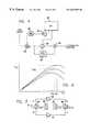
- FIG. 6is a graph illustrating amplifier output power versus input power for three different bias conditions.
- the present applicationsatisfies the need for an RFID interrogator having a receiver/transmitter architecture that attenuates certain inherent noise sources in order to achieve increased read range and reduced error rate of the received data.
- a receiver/transmitter architecturethat attenuates certain inherent noise sources in order to achieve increased read range and reduced error rate of the received data.
- the interrogator 10comprises a microcontroller module 20 , a digital signal processor (DSP) module 30 , and a radio module 40 .
- the microcontroller module 20provides control over high level operation of the interrogator 10 and communicates with an external network and peripheral devices.
- the DSP module 30provides direct control over all operations of the radio module 40 in response to high level commands provided by the microcontroller module 20 , and processes data signals received from the tag 15 .
- the radio module 40provides for RF communications to/from the tag 15 .
- the tag 15is disposed in proximity to the interrogator 10 , and has an antenna 17 that radiates an RF backscattered signal in response to an RF transmission signal provided by the interrogator.
- the tag 15may either be powered from the modulated electromagnetic field provided by the interrogator 10 , or may contain its own internal power source, such as a battery.
- the radio module 40further comprises a transmitter portion 40 a , a receiver portion 40 b , a hybrid 50 , and an antenna 48 .
- the hybrid 50may further comprise a circulator.
- the transmitter portion 40 aincludes a local oscillator that generates an RF carrier frequency.
- the transmitter portion 40 asends a transmission signal modulated by the RF carrier frequency to the hybrid 50 , which in turn passes the signal to the antenna 48 .
- the antenna 48broadcasts the modulated signal and captures signals radiated by the tag 15 .
- the antenna 48then passes the captured signals back to the hybrid 50 , which forwards the signals to the receiver portion 40 b .
- the receiver portion 40 bmixes the captured signals with the RF carrier frequency generated by the local oscillator to directly downconvert the captured signals to a baseband information signal.
- the baseband information signalcomprises two components in quadrature, referred to as the I (in phase with respect to the transmitted carrier) and the Q (quadrature, 90° out of phase with respect to the carrier) signals.
- the hybrid 50connects the transmitter 40 a and receiver 40 b portions to the antenna 48 while isolating them from each other. In particular, the hybrid 50 allows the antenna 48 to send out a strong signal from the transmitter portion 40 a while simultaneously receiving a weak backscattered signal reflected from the transponder 15 .
- the microcontroller module 20comprises a microprocessor ( ⁇ p) 22 and a clock source 24 providing a clock signal to the microprocessor.
- the microprocessor 22supervises the high-level operation of the RFID interrogator. External application level command sequences are provided to the microprocessor 22 through a serial RS-232 port. The microprocessor 22 interprets these external commands and constructs a sequence of lower level commands for execution by the DSP module 30 .
- the microprocessor 22further includes an external interface (AUX_ 1 ) that permits another device, such as an infrared (IR) detector, to trigger the RFID interrogator to execute a command.
- IRinfrared
- the DSP module 30comprises a DSP 32 , a clock source 33 providing a clock signal to the DSP, a digital-to-analog converter (DAC) 34 , analog-to-digital converters (ADC) 36 , 38 , and band-pass filters 37 , 39 .
- the DSP 32receives commands from the microprocessor 22 and controls the radio module 40 .
- the DSP 32includes an external interface (AUX_ 2 ) that may be used to permit another device to directly control the DSP, such as to disable operation of the radio module 40 .
- the DSP 32provides a digital data output signal to the DAC 34 for modulating a carrier to transmit signals to the RFID transponder, as will be further described below.
- Received I and Q signals from the radio module 40pass through the respective band-pass filters 37 , 39 , and are converted to digital signals by the respective ADCs 36 , 38 .
- the bandpass filters 37 , 39may be provided by cascaded high-pass filters and low-pass filters.
- the DSP 32processes the digitized and filtered I and Q signals to recover the bit clock and encoded data, and provide the recovered data to the microcontroller module 20 .
- the radio module 40further comprises several subsystems, including an RF source subsystem, a modulator subsystem, an amplifier subsystem, a receiver subsystem, and an antenna connection subsystem. It should be appreciated that the RF source subsystem, the modulator subsystem and the amplifier subsystem correspond generally to the transmitter 40 a of FIG. 1, and the receiver subsystem corresponds generally to the receiver 40 b of FIG. 1 . These subsystems of the radio module 40 are provided with various noise reducing features. Each of these subsystems and their noise reducing features are described in further detail below.
- the RF source subsystemcomprises a clock source 42 , synthesized PLL sources 43 , 45 , amplifiers 44 , 46 , and switch 47 .
- the clock source 42provides a reference signal (e.g., 12 MHz) for the synthesized PLL sources 43 , 45 , and the DSP 32 programs the frequency channel of each PLL source into the desired band (e.g., 2.4 GHz).
- the amplifiers 44 , 46are connected to the PLL sources 43 , 45 , respectively, and provide buffering of the synthesizer outputs to prevent frequency pulling.
- the amplifiers 44 , 46are selectively enabled/disabled by control signals provided by the DSP 32 .
- the switch 47is controlled by the DSP 32 to select one of the synthesizer outputs to pass to the modulator subsystem (described below) as the RF carrier.
- a frequency hop sequencefollows the steps of: 1) disabling the amplifier subsystem (described below); 2) selecting one of the synthesizers by operation of the switch 47 ; and 3) enabling the amplifier subsystem.
- the steps of disabling/enabling the amplifier subsystemprevents RF outputs from the RFID interrogator while in the process of hopping to a new channel.
- the modulator subsystemmodulates an information signal onto the selected RF carrier from the RF source subsystem using on-off key modulation, wherein full amplitude corresponds to an on state (e.g., logical one) and zero amplitude corresponds to an off state (e.g., logical zero).
- the modulator subsystemincludes plural cascading modulation components in order to increase the dynamic range between the on and off states of the modulating signal.
- the dynamic range of any single stagemay be limited by the leakage in the stage or the symmetry of devices in the stage. More particularly, the modulator subsystem comprises a low-pass filter 52 , a mixer 54 , an amplifier 56 , a switch 58 and a resistor termination 59 .
- the output from the DAC 34controls the amplitude of the carrier, i.e., between the on and off states.
- the low-pass filter 52attenuates modulated signals that have high offset frequencies ( ⁇ 1 MHz) relative to the carrier.
- the mixer 54has a local oscillator input (L), an intermediate frequency input (I), and an RF output (R).
- the carrieris coupled to the local oscillator input L and the low-pass filtered information signal from the DSP 32 is coupled to the intermediate frequency input I.
- the mixer 54multiplies the carrier with the information signal to yield a modulated signal present at the RF output R.
- FIGS. 3A-3Dvarious waveforms are illustrated corresponding to the signals processed by the modulator subsystem.
- FIG. 3Aillustrates the carrier L(t) provided by the RF source subsystem to the L input of the mixer 54 .
- FIG. 3Billustrates the information signal from the DAC 34 into the I input of the mixer 54 , in which the signal switches between on and off states in correspondence with the data contained in the transmitted information signal.
- FIG. 3Cillustrates the combined carrier and information signal present at the output R, in which the amplitude of the carrier is modulated by the information signal.
- the mixer 54provides a first stage of modulation having roughly 15-25 dB of dynamic range between the on and off states. A portion of the carrier leaks through the mixer 54 as shown in FIG. 3C by the presence of a low amplitude sinusoidal waveform at the off states.
- the modulated signalpasses through two subsequent modulation stages. Following the mixer 54 , the modulated signal passes through the amplifier 56 and switch 58 . Both of these elements are directly controlled by the DSP 32 in unison. During on states of the modulated signal, the amplifier 56 is energized by the DSP to amplify the modulated signal and the switch 58 passes the amplified modulated signal therethrough to the amplifier subsystem (described below). Conversely, during off states of the modulated signal, the amplifier 56 is shut off by the DSP and the switch 58 passes the residual signal that leaks past the amplifier into the resistor termination 59 . The resistor termination 59 absorbs the residual leakage signal from the amplifier.
- the dynamic range of the modulated signal between on and off statesmay be increased to as much as 50 dB.
- the modulated signal v(t) that passes to the transmitter amplifier subsystemcontains an almost imperceptible amount of carrier leakage at the off states.
- the alternative modulator subsystemfurther includes a phase shift device 55 and a combiner 57 .
- the mixer 54provides a first stage of modulation in which the carrier is combined with an information signal.
- the amplifier 56is connected in parallel with the phase shift device 55 .
- the outputs of the amplifier 56 and the phase shift device 55are added together by the combiner 57 , and the combined signal passes to the amplifier subsystem.
- Both the amplifier 56 and the phase shift device 55are controlled by the DSP 32 .
- the phase shift device 55shifts the phase of the input signal by 180°.
- the amplifier 56is energized by the DSP to amplify the modulated signal and the phase shift device 55 is shut off.
- the combined signal that passes through the combiner 57has passed through two stages of modulation in the same manner as the preceding embodiment.
- the amplifier 56is shut off by the DSP and the phase shift device 55 reverses the phase of the modulated signal. Accordingly, the remaining carrier present in the modulated signal that leaks past the amplifier 56 is added to the inverse of the remaining carrier signal by the combiner 57 , to effectively cancel the signal.
- cascaded stagese.g., plural amplifier, preamplifier, mixer or switching stages
- cascaded stagese.g., plural amplifier, preamplifier, mixer or switching stages
- the modulated signalis amplified to a desired level for transmission by the amplifier subsystem.
- the amplified modulated signalthen passes through the circulator 50 to the antenna connection subsystem (described below).
- Leakage of the transmitted signal into the receiver subsystemis a source of noise, and the amount of such leakage is determined by the quality of the match between the amplifier subsystem and the circulator 50 .
- two individual power amplifiers and two 90° couplersare combined to create a single high power amplifier that has twice the output power capacity and better matching characteristics than the individual amplifiers.
- the amplifier subsystemcomprises quadrature hybrids 62 , 68 and power amplifiers 64 , 66 .
- the first quadrature hybrid 62splits the modulated signal at the input of the amplifier subsystem into two signals differing in phase by 90°. The two signals are coupled into the power amplifiers 64 , 66 , respectively.
- the gain of the power amplifiers 64 , 66is controlled by control signals provided by the DSP 32 .
- the amplified signalsare recombined by the second quadrature hybrid 68 at the output of the amplifier subsystem.
- each one of the quadrature hybrids 62 , 68has an isolated port coupled to a respective resistor termination 65 , 67 .
- Reflected power from the power amplifiers 64 , 66 in either the forward or reverse directionsis coupled through the isolated ports of the quadrature hybrids 62 , 68 and into the resistor termination 65 , 67 for attenuation.
- the quadrature combination of the ampified signalsserves to reduce even harmonics of the combined signal and improves the return loss of the input and output to the amplifier subsystem.
- the power amplifiers 64 , 66operate in a saturated gain mode, and in this mode, the output power is determined by the voltage bias on the amplifier. Since the RFID interrogator receives and transmits signals simultaneously, received signals are processed at frequencies that may be slightly offset from the transmitted signal. At very low offset frequencies, amplitude and phase noise from within the radio module 40 of the RFID interrogator may cause noise and/or interference to detecting and receiving signals. Amplitude noise can propagate through the transmitter 40 a to the receiver 40 b without any attenuation relative to the desired received signal. By placing the power amplifiers 64 , 66 in a gain saturated state, the amplitude fluctuations in the transmitted signal are greatly reduced.
- FIG. 6a graph illustrating amplifier output power versus input power for three different bias conditions is shown.
- amplifierstypically operate in a linear region in which the output power is proportional to the input power.
- the ratio of output power to the input poweris referred to as the gain of the amplifier.
- the amplifiermoves out of the linear region and the output power thereby increases at a smaller rate.
- the saturated output power levelAs the input power keeps increasing, the output power reaches a maximum level, known as the saturated output power level. Further increases in the input power after the output power has saturated may actually cause a decrease in output power.
- the amplifierhas a differential gain of zero, wherein an infinitesimal change in the input power will not change the output power.
- the saturated output powerdepends on the DC bias conditions on the amplifier, and as the DC voltage supply bias to the power amplifiers 64 , 66 increases, the saturated power also increases.
- the graph of FIG. 6shows three different saturated power levels for the power amplifiers 64 , 66 , and it should be appreciated that the input power necessary for saturating the power amplifiers differs for each bias condition.
- Operating the power amplifiers 64 , 66 in the saturated modeis advantageous for two reasons. First, the output power over temperature is extremely stable since the DC voltage regulators effectively control the RF output power in the saturated mode, and the regulators are temperature stabilized. Second, since the saturated mode provides a differential gain of zero, any amplitude fluctuations that would leak into the receiver subsystem and cause interference are virtually eliminated from the amplifier output signal.
- the circulator 50separates and isolates the outgoing transmitted signals and incoming received signals.
- Transmitted signalspass through a directional coupler 72 to the antenna connection subsystem, which couples the transmitted signals into a selected antenna for transmission to an RFID transponder.
- the antenna connection subsystemcomprises an RF switch 74 , low-pass filters 75 , 76 , and antennas 77 , 78 .
- the RF switch 74is controlled by the DSP 32 to select one of the two antennas 77 , 78 for operation.
- the low-pass filters 75 , 76attenuate the harmonics of the RF fundamental frequency to prevent excessive emissions into FCC restricted frequency bands.
- received signalspass from the antennas 77 , 78 through the directional coupler and the circulator to the receiver subsystem.
- the receiver subsystemdemodulates the received signals and passes the demodulated signals to the DSP 32 for data processing.
- the received signalsare demodulated in a homodyne mode and are thereby directly downconverted to baseband without the use of intermediate frequency (IF) demodulation stages.
- the receiver subsystemcomprises mixer 82 , high-pass filters 84 , 86 , resistor terminations 85 , 87 , low-pass filters 92 , 94 and low noise amplifiers 93 , 95 .
- the mixer 82has a local oscillator input (L), an RF input (R), and I and Q outputs.
- the received signalpasses through the circulator 50 and is coupled to the RF input R.
- the carrierpasses through the circulator 50 in the opposite direction of the received signal, and is coupled by the directional coupler 72 into the local oscillator input L.
- the mixer 54multiplies the carrier with the received RF signal to yield demodulated I and Q signal components.
- the I and Q signal componentspass through the low-pass filters 94 , 92 and low noise amplifiers 95 , 93 , respectively, and are provided to the DSP module 30 . Within the DSP module 30 , the low-pass filtered I and Q signal components pass through the band-pass filters 39 , 37 , respectively.
- the bandwidth of these band-pass filters 39 , 37correspond to the single-sideband bandwidth of the receiver channel bandwidth (e.g., 200 kHz).
- the outputs of these band-pass filters 39 , 37are then sampled by ADCs 38 , 36 and fed into the DSP 32 .
- the I and Q outputs of the mixer 82are further coupled to the high-pass filters 86 , 84 , which are in turn coupled to respective resistor terminations 87 , 85 .
- the power from the fundamental carrier frequency and its harmonicsare absorbed by the resistor terminations 87 , 85 , while the low frequency data signals from the RFID transponder are not attenuated.
- the carrier frequencymay be expressed as sin ⁇ t
- the received RF signalmay be expressed as A(t) sin ⁇ t.
- the I signal componentrepresents the carrier frequency multiplied with the received RF signal, as follows:
- the first element of the expression, A(t)/2,represents the low frequency portion of the signal component I
- the second element of the expression, 1 ⁇ 2(A(t) sin 2 ⁇ t)represents the high frequency portion of the signal component I.
- the Q signal componentis calculated in a similar manner, except that it contains a phase shift of 90°.
- the low-pass filters 92 , 94permit the low frequency portion of the signal component to pass to the DSP 32
- the high-pass filters 84 , 86permit the high frequency portion of the signal components to pass to the resistor terminations 85 , 87 .
- the resistor terminations 85 , 87attenuate the high frequency portion of the signal components in order to prevent its reflection back to the mixer 82 .
- the receiver subsystemprevents the carrier and its harmonics from mixing together and generating noise or interference at baseband frequencies at which the RFID transponder signals are to be processed.
- the reference signali.e., carrier
- the reference signalshould be coupled from a location that is proportional to the leakage into the RF input R of the mixer 82 . Accordingly, the directional coupler 72 that provides the reference signal is disposed in close proximity to the source of leakage, as shown in FIG. 2 .
Landscapes
- Engineering & Computer Science (AREA)
- Artificial Intelligence (AREA)
- Computer Vision & Pattern Recognition (AREA)
- Physics & Mathematics (AREA)
- General Physics & Mathematics (AREA)
- Theoretical Computer Science (AREA)
- Transceivers (AREA)
Abstract
Description
Claims (42)
Priority Applications (1)
| Application Number | Priority Date | Filing Date | Title |
|---|---|---|---|
| US09/390,461US6639509B1 (en) | 1998-03-16 | 1999-09-07 | System and method for communicating with an RFID transponder with reduced noise and interference |
Applications Claiming Priority (7)
| Application Number | Priority Date | Filing Date | Title |
|---|---|---|---|
| US7822698P | 1998-03-16 | 1998-03-16 | |
| US7810098P | 1998-03-16 | 1998-03-16 | |
| US10763198P | 1998-11-09 | 1998-11-09 | |
| US10854698P | 1998-11-16 | 1998-11-16 | |
| US10934598P | 1998-11-20 | 1998-11-20 | |
| US26890199A | 1999-03-16 | 1999-03-16 | |
| US09/390,461US6639509B1 (en) | 1998-03-16 | 1999-09-07 | System and method for communicating with an RFID transponder with reduced noise and interference |
Related Parent Applications (1)
| Application Number | Title | Priority Date | Filing Date |
|---|---|---|---|
| US26890199AContinuation-In-Part | 1998-03-16 | 1999-03-16 |
Publications (1)
| Publication Number | Publication Date |
|---|---|
| US6639509B1true US6639509B1 (en) | 2003-10-28 |
Family
ID=29255720
Family Applications (1)
| Application Number | Title | Priority Date | Filing Date |
|---|---|---|---|
| US09/390,461Expired - LifetimeUS6639509B1 (en) | 1998-03-16 | 1999-09-07 | System and method for communicating with an RFID transponder with reduced noise and interference |
Country Status (1)
| Country | Link |
|---|---|
| US (1) | US6639509B1 (en) |
Cited By (89)
| Publication number | Priority date | Publication date | Assignee | Title |
|---|---|---|---|---|
| US20020127970A1 (en)* | 2000-12-07 | 2002-09-12 | Martinez Rene D. | RFID interrogator having customized radio parameters with local memory storage |
| US20040048579A1 (en)* | 2002-09-05 | 2004-03-11 | Honeywell International Inc. | RFID tag and communication protocol for long range tag communications and power efficiency |
| US20040066287A1 (en)* | 2002-10-03 | 2004-04-08 | Breed David S. | Apparatus for boosting signals from a signal-generating device |
| US20040135700A1 (en)* | 2002-07-22 | 2004-07-15 | Fockens Tallienco Wieand H. | Switching modulator |
| US20040203478A1 (en)* | 2002-10-10 | 2004-10-14 | Scott Jeffrey Wayne | Rfid receiver apparatus and method |
| RU2241243C1 (en)* | 2004-01-26 | 2004-11-27 | Общество с ограниченной ответственностью "Альтоника" | Transportation vehicle user radio frequency identification system |
| US20050011003A1 (en)* | 2003-06-21 | 2005-01-20 | Davis Philip Nigel | Sling attachment device |
| US20050070234A1 (en)* | 2003-09-30 | 2005-03-31 | Jensen Henrik T. | Translational loop RF transmitter architecture for GSM radio |
| US20050099270A1 (en)* | 2003-11-10 | 2005-05-12 | Impinj, Inc. | RFID tags adjusting to different regulatory environments, and RFID readers to so adjust them and methods |
| US20050136878A1 (en)* | 2003-12-19 | 2005-06-23 | Shahla Khorram | Radio frequency integrated circuit layout with noise immunity border |
| US20050136879A1 (en)* | 2003-12-19 | 2005-06-23 | Shahla Khorram | Radio frequency integrated circuit having reduced receiver noise levels |
| US20050156723A1 (en)* | 2004-01-20 | 2005-07-21 | Masaki Fujii | Transponder startup control method and interrogator for tire pressure monitoring system |
| US20050179521A1 (en)* | 2004-02-12 | 2005-08-18 | Intermec Ip Corp. | Frequency hopping method for RFID tag |
| US6945935B1 (en)* | 1999-03-04 | 2005-09-20 | Anthony Corry Sasse | Wireless sleep monitoring |
| US20050225433A1 (en)* | 2004-04-13 | 2005-10-13 | Diorio Christopher J | Method and system to backscatter modulate a radio-frequency signal from an RFID tag in accordance with both an oscillation frequency signal and a command signal |
| US20050225436A1 (en)* | 2004-04-13 | 2005-10-13 | Diorio Christopher J | Method and system to calibrate an oscillator within an RFID circuit responsive to a received update value |
| US20050225434A1 (en)* | 2004-04-13 | 2005-10-13 | Diorio Christopher J | Method and system to generate modulator and demodulator clock signals within an RFID circuit utilizing a multi-oscillator architecture |
| US20050240370A1 (en)* | 2004-04-13 | 2005-10-27 | Diorio Christopher J | Method and system to calibrate an oscillator within an RFID circuit by selecting a calibration value from a plurality of stored calibration values |
| US20050237844A1 (en)* | 2004-04-13 | 2005-10-27 | Hyde John D | Method and apparatus for controlled persistent ID flag for RFID applications |
| US20050240369A1 (en)* | 2004-04-13 | 2005-10-27 | Diorio Christopher J | Method and system to calibrate an oscillator within an RFID circuit utilizing a test signal supplied to the RFID circuit |
| US20060068711A1 (en)* | 2004-09-16 | 2006-03-30 | Chiu Lihu M | RFID verifier |
| US20060094392A1 (en)* | 2004-11-01 | 2006-05-04 | Youn Tai W | Backscatter receiver maintaining sensitivity with varying power levels |
| US20060101451A1 (en)* | 2004-11-01 | 2006-05-11 | Man Ha Fong | Transferring configuration data |
| US20060109128A1 (en)* | 2004-11-19 | 2006-05-25 | Bernard Barink | Homodyne RFID receiver and method |
| US20060109127A1 (en)* | 2004-11-19 | 2006-05-25 | Bernard Barink | Homodyne single mixer receiver and method therefor |
| US20060111051A1 (en)* | 2004-11-19 | 2006-05-25 | Bernard Barink | Homodyne RFID receiver and method |
| US20060152369A1 (en)* | 2004-12-30 | 2006-07-13 | Jukka Reunamaki | Ultra wideband radio frequency identification techniques |
| US20060163370A1 (en)* | 2005-01-21 | 2006-07-27 | Impini, Inc. | RFID system components implementing adjusted backscatter calculations and methods |
| EP1710726A1 (en) | 2005-04-06 | 2006-10-11 | Fujitsu Limited | Carrier sensing method and RFID transeiver device using the same |
| US20060252398A1 (en)* | 2005-05-09 | 2006-11-09 | Park Kyung H | Receiver of RFID reader for eliminating leakage signal |
| US20060261956A1 (en)* | 2004-04-13 | 2006-11-23 | Sundstrom Kurt E | Adjusting RFID waveform shape in view of signal from another reader |
| US20060261952A1 (en)* | 2004-04-13 | 2006-11-23 | Kavounas Gregory T | Adjusting RFID waveform shape in view of signal from an RFID tag |
| US20060261955A1 (en)* | 2004-04-13 | 2006-11-23 | Humes Todd E | Performance driven adjustment of RFID waveform shape |
| US20060261954A1 (en)* | 2004-04-13 | 2006-11-23 | Paul Dietrich | Reconstructing RFID waveform shape for reuse in individual channel |
| US20060261953A1 (en)* | 2004-04-13 | 2006-11-23 | Diorio Christopher J | Adjusting RFID waveform shape in view of detected RF energy |
| US20060267690A1 (en)* | 2005-05-30 | 2006-11-30 | Semiconductor Energy Laboratory Co. Ltd. | Clock generation circuit and semiconductor device provided therewith |
| US20060284724A1 (en)* | 2003-09-04 | 2006-12-21 | Gerold Sept-Enzel | Device for receiving signals for controlling a function in a vehicle |
| US20070030153A1 (en)* | 2005-08-08 | 2007-02-08 | Ensyc Technologies | Low cost RFID labeling device |
| US20070041476A1 (en)* | 2005-08-16 | 2007-02-22 | Ls Industrial Systems Co., Ltd. | Rfid reader |
| US20070040606A1 (en)* | 2005-08-19 | 2007-02-22 | Applied Wireless Identifications, Inc. | Amplitude modulator |
| US20070040681A1 (en)* | 2005-08-19 | 2007-02-22 | Ensyc Technologies | Low cost RFID system |
| KR100690069B1 (en) | 2006-03-31 | 2007-03-08 | 햄펙스 주식회사 | RFID Reader |
| WO2007024416A3 (en)* | 2005-08-19 | 2007-05-18 | Applied Wireless Identificatio | Rfid reader and components thereof |
| WO2007035644A3 (en)* | 2005-09-16 | 2007-07-19 | George Schmitt & Company Inc | System and method for validating radio frequency identification tags |
| US20070176746A1 (en)* | 2006-01-17 | 2007-08-02 | Integrant Technologies Inc. | Rfid reader and rfid system |
| US20070178866A1 (en)* | 2006-01-31 | 2007-08-02 | Ibm Corporation | Receiver and integrated AM-FM/IQ demodulators for gigabit-rate data detection |
| US20070176747A1 (en)* | 2006-01-17 | 2007-08-02 | Integrant Technologies Inc. | Reader for rfid and rfid system |
| US7258276B2 (en) | 2000-10-20 | 2007-08-21 | Promega Corporation | Radio frequency identification method and system of distributing products |
| US20070206704A1 (en)* | 2006-03-03 | 2007-09-06 | Applied Wireless Identification Group, Inc. | RFID reader with adaptive carrier cancellation |
| US20070206701A1 (en)* | 2006-03-03 | 2007-09-06 | Applied Wireless Identification Group, Inc. | RFID reader with digital waveform encoding and digital decoding |
| US20070207732A1 (en)* | 2006-03-02 | 2007-09-06 | Broadcom Corporation, A California Corporation | RFID reader architecture |
| US20070206705A1 (en)* | 2006-03-03 | 2007-09-06 | Applied Wireless Identification Group, Inc. | RFID reader with adjustable filtering and adaptive backscatter processing |
| KR100772459B1 (en)* | 2007-01-24 | 2007-11-01 | 주식회사 유컴테크놀러지 | RDF tag reading method and RDF tag reader using same |
| US20080014893A1 (en)* | 2006-06-30 | 2008-01-17 | Semiconductor Energy Laboratory Co., Ltd. | Semiconductor device and electronic device having the same |
| US20080079542A1 (en)* | 2006-09-26 | 2008-04-03 | Broadcom Corporation, A California Corporation | Radio frequency identification (RFID) carrier and system |
| US20080079546A1 (en)* | 2006-09-29 | 2008-04-03 | Sensormatic Electronics Corporation | Programmable chip design for radio frequency signal generation and method therefor |
| US20080088416A1 (en)* | 2006-10-03 | 2008-04-17 | John Frederick Crooks | Methods and Apparatus for Analyzing Signal Conditions Affecting Operation of an RFID Communication Device |
| US20080135378A1 (en)* | 2004-08-17 | 2008-06-12 | Paolo Mignano | Sorting and Distributing System and Method For Transmitting Power and Data |
| US20080174410A1 (en)* | 2007-01-08 | 2008-07-24 | Jagannathan Sarangapani | Decentralized radio frequency identification system |
| RU2334644C2 (en)* | 2006-07-04 | 2008-09-27 | ЛюксЛабс Лтд. | Railway freight services recording system |
| US20090012882A1 (en)* | 2007-03-02 | 2009-01-08 | Jagannathan Sarangapani | Adaptive inventory management system |
| US7561022B2 (en) | 2004-01-13 | 2009-07-14 | George Schmitt & Company, Inc. | System and method for validating radio frequency identification tags |
| US20090303007A1 (en)* | 2006-07-10 | 2009-12-10 | Byung Hoon Ryou | Multiple band rfid reader device |
| RU2378661C1 (en)* | 2008-04-24 | 2010-01-10 | Борис Алексеевич Хозяинов | Method to determine storage of objects using radio-frequency marks |
| US20100016032A1 (en)* | 2008-07-15 | 2010-01-21 | Research In Motion Limited | Mobile wireless communications device with separate in-phase and quadrature power amplification |
| US7661591B2 (en) | 2000-10-20 | 2010-02-16 | Promega Corporation | RF point of sale and delivery method and system using communication with remote computer and having features to read a large number of RF tags |
| US7710275B2 (en) | 2007-03-16 | 2010-05-04 | Promega Corporation | RFID reader enclosure and man-o-war RFID reader system |
| USD626949S1 (en) | 2008-02-20 | 2010-11-09 | Vocollect Healthcare Systems, Inc. | Body-worn mobile device |
| US7830262B1 (en) | 2006-04-25 | 2010-11-09 | Impinj, Inc. | Adjusting communication parameters while inventorying RFID tags |
| USD643013S1 (en) | 2010-08-20 | 2011-08-09 | Vocollect Healthcare Systems, Inc. | Body-worn mobile device |
| USD643400S1 (en) | 2010-08-19 | 2011-08-16 | Vocollect Healthcare Systems, Inc. | Body-worn mobile device |
| RU2444025C1 (en)* | 2011-01-26 | 2012-02-27 | Открытое акционерное общество "Авангард" | Method of determining object storage place using radio-frequency labels |
| WO2012027317A1 (en)* | 2010-08-25 | 2012-03-01 | Clairvoyant Technology Llc | Rf metal detector and electronic article surveillance system using same |
| US8128422B2 (en) | 2002-06-27 | 2012-03-06 | Vocollect, Inc. | Voice-directed portable terminals for wireless communication systems |
| US8169312B2 (en) | 2009-01-09 | 2012-05-01 | Sirit Inc. | Determining speeds of radio frequency tags |
| US8226003B2 (en) | 2006-04-27 | 2012-07-24 | Sirit Inc. | Adjusting parameters associated with leakage signals |
| US8248212B2 (en) | 2007-05-24 | 2012-08-21 | Sirit Inc. | Pipelining processes in a RF reader |
| US8386261B2 (en) | 2008-11-14 | 2013-02-26 | Vocollect Healthcare Systems, Inc. | Training/coaching system for a voice-enabled work environment |
| US8416079B2 (en) | 2009-06-02 | 2013-04-09 | 3M Innovative Properties Company | Switching radio frequency identification (RFID) tags |
| US8427316B2 (en) | 2008-03-20 | 2013-04-23 | 3M Innovative Properties Company | Detecting tampered with radio frequency identification tags |
| US8446256B2 (en) | 2008-05-19 | 2013-05-21 | Sirit Technologies Inc. | Multiplexing radio frequency signals |
| US8659397B2 (en) | 2010-07-22 | 2014-02-25 | Vocollect, Inc. | Method and system for correctly identifying specific RFID tags |
| KR101416991B1 (en)* | 2007-02-09 | 2014-07-08 | 엘지이노텍 주식회사 | RFID Transmission and Reception System |
| US20160001741A1 (en)* | 2014-07-03 | 2016-01-07 | Directed, Llc | Apparatus and method for bypassing wireless vehicle immobilizers |
| US9441939B2 (en) | 2010-08-25 | 2016-09-13 | Clairvoyant Technology Llc | System for object detection using radio frequency reflection |
| CN108268807A (en)* | 2017-12-22 | 2018-07-10 | 中国电子科技集团公司第三十研究所 | A kind of demodulation method to ultrahigh frequency RFID signal under low signal-to-noise ratio |
| US10062025B2 (en) | 2012-03-09 | 2018-08-28 | Neology, Inc. | Switchable RFID tag |
| USRE47599E1 (en) | 2000-10-20 | 2019-09-10 | Promega Corporation | RF point of sale and delivery method and system using communication with remote computer and having features to read a large number of RF tags |
| CN115577725A (en)* | 2022-10-26 | 2023-01-06 | 深圳市国芯物联科技有限公司 | Baseband signal processing SOC chip of multi-protocol UHF RFID reader-writer |
Citations (50)
| Publication number | Priority date | Publication date | Assignee | Title |
|---|---|---|---|---|
| US4075632A (en) | 1974-08-27 | 1978-02-21 | The United States Of America As Represented By The United States Department Of Energy | Interrogation, and detection system |
| US4360810A (en) | 1981-01-19 | 1982-11-23 | The United States Of America As Represented By The United States Department Of Energy | Multichannel homodyne receiver |
| US4782345A (en) | 1986-07-29 | 1988-11-01 | Amtech Corporation | Transponder antenna |
| US4786907A (en) | 1986-07-14 | 1988-11-22 | Amtech Corporation | Transponder useful in a system for identifying objects |
| EP0294963A2 (en) | 1987-06-10 | 1988-12-14 | Amtech Technology Corporation | Programmer for identification system |
| US4816389A (en) | 1984-07-13 | 1989-03-28 | Institut Pasteur | Probe for DNA and a process for the detection of "shigellae" and entero-invasive strains of Escherichia coli |
| US4853705A (en) | 1988-05-11 | 1989-08-01 | Amtech Technology Corporation | Beam powered antenna |
| US4864158A (en) | 1988-01-28 | 1989-09-05 | Amtech Corporation | Rapid signal validity checking apparatus |
| US4888591A (en) | 1988-10-06 | 1989-12-19 | Amtech Technology Corporation | Signal discrimination system |
| US4999636A (en) | 1989-02-17 | 1991-03-12 | Amtech Technology Corporation | Range limiting system |
| US5030807A (en) | 1990-01-16 | 1991-07-09 | Amtech Corporation | System for reading and writing data from and into remote tags |
| US5055659A (en) | 1990-02-06 | 1991-10-08 | Amtech Technology Corp. | High speed system for reading and writing data from and into remote tags |
| US5347280A (en)* | 1993-07-02 | 1994-09-13 | Texas Instruments Deutschland Gmbh | Frequency diversity transponder arrangement |
| EP0646983A2 (en) | 1993-10-04 | 1995-04-05 | Amtech Corporation | Modulated backscatter microstrip patch antenna |
| US5479160A (en) | 1993-10-01 | 1995-12-26 | Amtech Corporation | Low level RF threshold detector |
| US5485520A (en) | 1993-10-07 | 1996-01-16 | Amtech Corporation | Automatic real-time highway toll collection from moving vehicles |
| US5504485A (en) | 1994-07-21 | 1996-04-02 | Amtech Corporation | System for preventing reading of undesired RF signals |
| US5510795A (en) | 1994-11-10 | 1996-04-23 | Amtech Corporation | Single antenna location and direction finding system |
| US5521601A (en) | 1995-04-21 | 1996-05-28 | International Business Machines Corporation | Power-efficient technique for multiple tag discrimination |
| US5528222A (en) | 1994-09-09 | 1996-06-18 | International Business Machines Corporation | Radio frequency circuit and memory in thin flexible package |
| US5538803A (en) | 1994-11-23 | 1996-07-23 | International Business Machines Corporation | Multibit tag using Barkhausen effect |
| US5550547A (en) | 1994-09-12 | 1996-08-27 | International Business Machines Corporation | Multiple item radio frequency tag identification protocol |
| US5552778A (en) | 1994-11-23 | 1996-09-03 | International Business Machines Corporation | Multibit bimorph magnetic tags using acoustic or magnetic interrogation for identification of an object coupled thereto |
| US5554974A (en) | 1994-11-23 | 1996-09-10 | International Business Machines Corporation | Encodable tag with radio frequency readout |
| US5563583A (en) | 1994-11-23 | 1996-10-08 | International Business Machines Corporation | Multibit magnetic radio frequency tag using micromechanics |
| US5565847A (en) | 1994-11-23 | 1996-10-15 | International Business Machines Corporation | Magnetic tag using acoustic or magnetic interrogation |
| US5606323A (en) | 1995-08-31 | 1997-02-25 | International Business Machines Corporation | Diode modulator for radio frequency transponder |
| US5635693A (en) | 1995-02-02 | 1997-06-03 | International Business Machines Corporation | System and method for tracking vehicles in vehicle lots |
| US5673037A (en) | 1994-09-09 | 1997-09-30 | International Business Machines Corporation | System and method for radio frequency tag group select |
| US5680106A (en) | 1995-10-27 | 1997-10-21 | International Business Machines Corporation | Multibit tag with stepwise variable frequencies |
| US5682143A (en) | 1994-09-09 | 1997-10-28 | International Business Machines Corporation | Radio frequency identification tag |
| US5729201A (en) | 1995-06-29 | 1998-03-17 | International Business Machines Corporation | Identification tags using amorphous wire |
| US5737710A (en) | 1995-11-07 | 1998-04-07 | Amtech Corporation | Automated vehicle parking system for a plurality of remote parking facilities |
| US5736929A (en) | 1996-06-07 | 1998-04-07 | International Business Machines Corporation | System for concealed serialization utilizing a soft magnetic antitheft element |
| US5739754A (en) | 1996-07-29 | 1998-04-14 | International Business Machines Corporation | Circuit antitheft and disabling mechanism |
| WO1998016070A1 (en) | 1996-10-07 | 1998-04-16 | Amtech Corporation | Integrated multi-meter and wireless communication link |
| US5767789A (en) | 1995-08-31 | 1998-06-16 | International Business Machines Corporation | Communication channels through electrically conducting enclosures via frequency selective windows |
| US5771021A (en) | 1993-10-04 | 1998-06-23 | Amtech Corporation | Transponder employing modulated backscatter microstrip double patch antenna |
| US5777561A (en) | 1996-09-30 | 1998-07-07 | International Business Machines Corporation | Method of grouping RF transponders |
| US5786626A (en) | 1996-03-25 | 1998-07-28 | Ibm Corporation | Thin radio frequency transponder with leadframe antenna structure |
| US5812065A (en) | 1995-08-14 | 1998-09-22 | International Business Machines Corporation | Modulation of the resonant frequency of a circuit using an energy field |
| US5821859A (en) | 1996-06-07 | 1998-10-13 | Ibm Corporation | Concealed magnetic ID code and antitheft tag |
| US5828318A (en) | 1996-05-08 | 1998-10-27 | International Business Machines Corporation | System and method for selecting a subset of autonomous and independent slave entities |
| US5826328A (en) | 1996-03-25 | 1998-10-27 | International Business Machines | Method of making a thin radio frequency transponder |
| US5828693A (en) | 1996-03-21 | 1998-10-27 | Amtech Corporation | Spread spectrum frequency hopping reader system |
| US5850187A (en) | 1996-03-27 | 1998-12-15 | Amtech Corporation | Integrated electronic tag reader and wireless communication link |
| US5850181A (en) | 1996-04-03 | 1998-12-15 | International Business Machines Corporation | Method of transporting radio frequency power to energize radio frequency identification transponders |
| US5874902A (en) | 1996-07-29 | 1999-02-23 | International Business Machines Corporation | Radio frequency identification transponder with electronic circuit enabling/disabling capability |
| US5896060A (en)* | 1996-12-23 | 1999-04-20 | Micron Technology, Inc. | DPSK demodulator which may be used in an interrogator of a remote intelligence communication system |
| US6184841B1 (en)* | 1996-12-31 | 2001-02-06 | Lucent Technologies Inc. | Antenna array in an RFID system |
- 1999
- 1999-09-07USUS09/390,461patent/US6639509B1/ennot_activeExpired - Lifetime
Patent Citations (53)
| Publication number | Priority date | Publication date | Assignee | Title |
|---|---|---|---|---|
| US4075632A (en) | 1974-08-27 | 1978-02-21 | The United States Of America As Represented By The United States Department Of Energy | Interrogation, and detection system |
| US4360810A (en) | 1981-01-19 | 1982-11-23 | The United States Of America As Represented By The United States Department Of Energy | Multichannel homodyne receiver |
| US4816389A (en) | 1984-07-13 | 1989-03-28 | Institut Pasteur | Probe for DNA and a process for the detection of "shigellae" and entero-invasive strains of Escherichia coli |
| US4786907A (en) | 1986-07-14 | 1988-11-22 | Amtech Corporation | Transponder useful in a system for identifying objects |
| US4782345A (en) | 1986-07-29 | 1988-11-01 | Amtech Corporation | Transponder antenna |
| EP0294963A2 (en) | 1987-06-10 | 1988-12-14 | Amtech Technology Corporation | Programmer for identification system |
| US4835377A (en) | 1987-06-10 | 1989-05-30 | Brown Richard R | Programmer for identification system |
| US4864158A (en) | 1988-01-28 | 1989-09-05 | Amtech Corporation | Rapid signal validity checking apparatus |
| US4853705A (en) | 1988-05-11 | 1989-08-01 | Amtech Technology Corporation | Beam powered antenna |
| US4888591A (en) | 1988-10-06 | 1989-12-19 | Amtech Technology Corporation | Signal discrimination system |
| US4999636A (en) | 1989-02-17 | 1991-03-12 | Amtech Technology Corporation | Range limiting system |
| US5030807A (en) | 1990-01-16 | 1991-07-09 | Amtech Corporation | System for reading and writing data from and into remote tags |
| US5055659A (en) | 1990-02-06 | 1991-10-08 | Amtech Technology Corp. | High speed system for reading and writing data from and into remote tags |
| US5347280A (en)* | 1993-07-02 | 1994-09-13 | Texas Instruments Deutschland Gmbh | Frequency diversity transponder arrangement |
| US5479160A (en) | 1993-10-01 | 1995-12-26 | Amtech Corporation | Low level RF threshold detector |
| EP0646983A2 (en) | 1993-10-04 | 1995-04-05 | Amtech Corporation | Modulated backscatter microstrip patch antenna |
| US5825329A (en) | 1993-10-04 | 1998-10-20 | Amtech Corporation | Modulated backscatter microstrip patch antenna |
| US5771021A (en) | 1993-10-04 | 1998-06-23 | Amtech Corporation | Transponder employing modulated backscatter microstrip double patch antenna |
| US5485520A (en) | 1993-10-07 | 1996-01-16 | Amtech Corporation | Automatic real-time highway toll collection from moving vehicles |
| US5504485A (en) | 1994-07-21 | 1996-04-02 | Amtech Corporation | System for preventing reading of undesired RF signals |
| US5528222A (en) | 1994-09-09 | 1996-06-18 | International Business Machines Corporation | Radio frequency circuit and memory in thin flexible package |
| US5682143A (en) | 1994-09-09 | 1997-10-28 | International Business Machines Corporation | Radio frequency identification tag |
| US5673037A (en) | 1994-09-09 | 1997-09-30 | International Business Machines Corporation | System and method for radio frequency tag group select |
| US5550547A (en) | 1994-09-12 | 1996-08-27 | International Business Machines Corporation | Multiple item radio frequency tag identification protocol |
| US5510795A (en) | 1994-11-10 | 1996-04-23 | Amtech Corporation | Single antenna location and direction finding system |
| US5565847A (en) | 1994-11-23 | 1996-10-15 | International Business Machines Corporation | Magnetic tag using acoustic or magnetic interrogation |
| US5563583A (en) | 1994-11-23 | 1996-10-08 | International Business Machines Corporation | Multibit magnetic radio frequency tag using micromechanics |
| US5554974A (en) | 1994-11-23 | 1996-09-10 | International Business Machines Corporation | Encodable tag with radio frequency readout |
| US5538803A (en) | 1994-11-23 | 1996-07-23 | International Business Machines Corporation | Multibit tag using Barkhausen effect |
| US5552778A (en) | 1994-11-23 | 1996-09-03 | International Business Machines Corporation | Multibit bimorph magnetic tags using acoustic or magnetic interrogation for identification of an object coupled thereto |
| US5635693A (en) | 1995-02-02 | 1997-06-03 | International Business Machines Corporation | System and method for tracking vehicles in vehicle lots |
| US5521601A (en) | 1995-04-21 | 1996-05-28 | International Business Machines Corporation | Power-efficient technique for multiple tag discrimination |
| US5729201A (en) | 1995-06-29 | 1998-03-17 | International Business Machines Corporation | Identification tags using amorphous wire |
| US5831532A (en) | 1995-06-29 | 1998-11-03 | International Business Machines Corporation | Identification tags using amorphous wire |
| US5812065A (en) | 1995-08-14 | 1998-09-22 | International Business Machines Corporation | Modulation of the resonant frequency of a circuit using an energy field |
| US5767789A (en) | 1995-08-31 | 1998-06-16 | International Business Machines Corporation | Communication channels through electrically conducting enclosures via frequency selective windows |
| US5606323A (en) | 1995-08-31 | 1997-02-25 | International Business Machines Corporation | Diode modulator for radio frequency transponder |
| US5680106A (en) | 1995-10-27 | 1997-10-21 | International Business Machines Corporation | Multibit tag with stepwise variable frequencies |
| US5737710A (en) | 1995-11-07 | 1998-04-07 | Amtech Corporation | Automated vehicle parking system for a plurality of remote parking facilities |
| US5828693A (en) | 1996-03-21 | 1998-10-27 | Amtech Corporation | Spread spectrum frequency hopping reader system |
| US5826328A (en) | 1996-03-25 | 1998-10-27 | International Business Machines | Method of making a thin radio frequency transponder |
| US5786626A (en) | 1996-03-25 | 1998-07-28 | Ibm Corporation | Thin radio frequency transponder with leadframe antenna structure |
| US5850187A (en) | 1996-03-27 | 1998-12-15 | Amtech Corporation | Integrated electronic tag reader and wireless communication link |
| US5850181A (en) | 1996-04-03 | 1998-12-15 | International Business Machines Corporation | Method of transporting radio frequency power to energize radio frequency identification transponders |
| US5828318A (en) | 1996-05-08 | 1998-10-27 | International Business Machines Corporation | System and method for selecting a subset of autonomous and independent slave entities |
| US5736929A (en) | 1996-06-07 | 1998-04-07 | International Business Machines Corporation | System for concealed serialization utilizing a soft magnetic antitheft element |
| US5821859A (en) | 1996-06-07 | 1998-10-13 | Ibm Corporation | Concealed magnetic ID code and antitheft tag |
| US5739754A (en) | 1996-07-29 | 1998-04-14 | International Business Machines Corporation | Circuit antitheft and disabling mechanism |
| US5874902A (en) | 1996-07-29 | 1999-02-23 | International Business Machines Corporation | Radio frequency identification transponder with electronic circuit enabling/disabling capability |
| US5777561A (en) | 1996-09-30 | 1998-07-07 | International Business Machines Corporation | Method of grouping RF transponders |
| WO1998016070A1 (en) | 1996-10-07 | 1998-04-16 | Amtech Corporation | Integrated multi-meter and wireless communication link |
| US5896060A (en)* | 1996-12-23 | 1999-04-20 | Micron Technology, Inc. | DPSK demodulator which may be used in an interrogator of a remote intelligence communication system |
| US6184841B1 (en)* | 1996-12-31 | 2001-02-06 | Lucent Technologies Inc. | Antenna array in an RFID system |
Non-Patent Citations (2)
| Title |
|---|
| "Multifunctional Credit Card Package" IBM Technical Disclosure Bulletin, vol. 38, No. 08, Aug. 1995, p. 17. |
| As "A Low-Power CMOS Integrated Circuit for Field-Powwered Radio Frequency Identification Tag" By Friedman et al., 1997 IEEE International Solid State Circuits Conference, PAper SA 17.5, pp. 294, 295, 474. |
Cited By (180)
| Publication number | Priority date | Publication date | Assignee | Title |
|---|---|---|---|---|
| US6945935B1 (en)* | 1999-03-04 | 2005-09-20 | Anthony Corry Sasse | Wireless sleep monitoring |
| US7791479B2 (en) | 2000-10-20 | 2010-09-07 | Promega Corporation | RFID point of sale and delivery method and system |
| US7967199B2 (en) | 2000-10-20 | 2011-06-28 | Promega Corporation | Radio frequency identification method and system of distributing products |
| US7661591B2 (en) | 2000-10-20 | 2010-02-16 | Promega Corporation | RF point of sale and delivery method and system using communication with remote computer and having features to read a large number of RF tags |
| US7735732B2 (en) | 2000-10-20 | 2010-06-15 | Promega Corporation | Radio frequency identification method and system of distributing products |
| US7784689B2 (en) | 2000-10-20 | 2010-08-31 | Promega Corporation | Radio frequency identification method and system of distributing products |
| USRE47599E1 (en) | 2000-10-20 | 2019-09-10 | Promega Corporation | RF point of sale and delivery method and system using communication with remote computer and having features to read a large number of RF tags |
| US7942321B2 (en) | 2000-10-20 | 2011-05-17 | Promega Corporation | Radio frequency identification method and system of disturbing products |
| US7591421B2 (en) | 2000-10-20 | 2009-09-22 | Promega Corporation | Radio frequency identification method and system of distributing products |
| US8025228B2 (en) | 2000-10-20 | 2011-09-27 | Promega Corporation | RF point of sale and delivery method and system using communication with remote computer and having features to read a large number of RF tags |
| US8113425B2 (en) | 2000-10-20 | 2012-02-14 | Promega Corporation | RF point of sale and delivery method and system using communication with remote computer and having features to read a large number of RF tags |
| US8231053B2 (en) | 2000-10-20 | 2012-07-31 | Promega Corporation | Radio frequency identification method and system of distributing products |
| US7258276B2 (en) | 2000-10-20 | 2007-08-21 | Promega Corporation | Radio frequency identification method and system of distributing products |
| USRE46326E1 (en) | 2000-10-20 | 2017-02-28 | Promega Corporation | RF point of sale and delivery method and system using communication with remote computer and having features to read a large number of RF tags |
| US7293705B2 (en) | 2000-10-20 | 2007-11-13 | Promega Corporation | Radio frequency identification method and system of distributing products |
| US7039359B2 (en)* | 2000-12-07 | 2006-05-02 | Intermec Ip Corp. | RFID interrogator having customized radio parameters with local memory storage |
| US20020127970A1 (en)* | 2000-12-07 | 2002-09-12 | Martinez Rene D. | RFID interrogator having customized radio parameters with local memory storage |
| US8128422B2 (en) | 2002-06-27 | 2012-03-06 | Vocollect, Inc. | Voice-directed portable terminals for wireless communication systems |
| US20040135700A1 (en)* | 2002-07-22 | 2004-07-15 | Fockens Tallienco Wieand H. | Switching modulator |
| US20040048579A1 (en)* | 2002-09-05 | 2004-03-11 | Honeywell International Inc. | RFID tag and communication protocol for long range tag communications and power efficiency |
| US7044387B2 (en)* | 2002-09-05 | 2006-05-16 | Honeywell International Inc. | RFID tag and communication protocol for long range tag communications and power efficiency |
| US7253725B2 (en) | 2002-10-03 | 2007-08-07 | Automotive Technologies International, Inc. | Apparatus and method for boosting signals from a signal-generating or modifying device |
| US20040066287A1 (en)* | 2002-10-03 | 2004-04-08 | Breed David S. | Apparatus for boosting signals from a signal-generating device |
| US20040203478A1 (en)* | 2002-10-10 | 2004-10-14 | Scott Jeffrey Wayne | Rfid receiver apparatus and method |
| US7155172B2 (en)* | 2002-10-10 | 2006-12-26 | Battelle Memorial Institute | RFID receiver apparatus and method |
| US20050011003A1 (en)* | 2003-06-21 | 2005-01-20 | Davis Philip Nigel | Sling attachment device |
| US20060284724A1 (en)* | 2003-09-04 | 2006-12-21 | Gerold Sept-Enzel | Device for receiving signals for controlling a function in a vehicle |
| US20050070234A1 (en)* | 2003-09-30 | 2005-03-31 | Jensen Henrik T. | Translational loop RF transmitter architecture for GSM radio |
| US7386283B2 (en)* | 2003-09-30 | 2008-06-10 | Broadcom Corporation | Translational loop RF transmitter architecture for GSM radio |
| US7026935B2 (en) | 2003-11-10 | 2006-04-11 | Impinj, Inc. | Method and apparatus to configure an RFID system to be adaptable to a plurality of environmental conditions |
| US7283037B2 (en) | 2003-11-10 | 2007-10-16 | Impinj, Inc. | RFID tags adjusting to different regulatory environments, and RFID readers to so adjust them and methods |
| US20050099270A1 (en)* | 2003-11-10 | 2005-05-12 | Impinj, Inc. | RFID tags adjusting to different regulatory environments, and RFID readers to so adjust them and methods |
| US20050099269A1 (en)* | 2003-11-10 | 2005-05-12 | Diorio Christopher J. | Method and apparatus to configure an RFID system to be adaptable to a plurality of environmental conditions |
| US7304579B2 (en) | 2003-11-10 | 2007-12-04 | Impinj, Inc. | RFID reader to select code modules |
| US20050136879A1 (en)* | 2003-12-19 | 2005-06-23 | Shahla Khorram | Radio frequency integrated circuit having reduced receiver noise levels |
| US7099648B2 (en)* | 2003-12-19 | 2006-08-29 | Broadcom Corporation | Radio frequency integrated circuit layout with noise immunity border |
| US20080036636A1 (en)* | 2003-12-19 | 2008-02-14 | Broadcom Corporation | Reduced noise radio frequency integrated circuit |
| US7305222B2 (en)* | 2003-12-19 | 2007-12-04 | Broadcom Corporation | Radio frequency integrated circuit having reduced receiver noise levels |
| US7583212B2 (en)* | 2003-12-19 | 2009-09-01 | Broadcom Corporation | Reduced noise radio frequency integrated circuit |
| US20050136878A1 (en)* | 2003-12-19 | 2005-06-23 | Shahla Khorram | Radio frequency integrated circuit layout with noise immunity border |
| US7420457B2 (en) | 2004-01-13 | 2008-09-02 | George Schmitt & Company, Inc. | System and method for validating radio frequency identification tags |
| US7561022B2 (en) | 2004-01-13 | 2009-07-14 | George Schmitt & Company, Inc. | System and method for validating radio frequency identification tags |
| US7336163B2 (en)* | 2004-01-20 | 2008-02-26 | Omron Corporation | Transponder startup control method and interrogator for tire pressure monitoring system |
| US20050156723A1 (en)* | 2004-01-20 | 2005-07-21 | Masaki Fujii | Transponder startup control method and interrogator for tire pressure monitoring system |
| RU2241243C1 (en)* | 2004-01-26 | 2004-11-27 | Общество с ограниченной ответственностью "Альтоника" | Transportation vehicle user radio frequency identification system |
| US20050179521A1 (en)* | 2004-02-12 | 2005-08-18 | Intermec Ip Corp. | Frequency hopping method for RFID tag |
| US7391329B2 (en) | 2004-04-13 | 2008-06-24 | Impinj, Inc. | Performance driven adjustment of RFID waveform shape |
| US20050237843A1 (en)* | 2004-04-13 | 2005-10-27 | Hyde John D | Method and apparatus for controlled persistent ID flag for RFID applications |
| US20070001856A1 (en)* | 2004-04-13 | 2007-01-04 | Diorio Christopher J | Radio-frequency identification tag with oscillator calibration |
| US20050225436A1 (en)* | 2004-04-13 | 2005-10-13 | Diorio Christopher J | Method and system to calibrate an oscillator within an RFID circuit responsive to a received update value |
| US7394324B2 (en) | 2004-04-13 | 2008-07-01 | Impinj, Inc. | Method and system to calibrate an oscillator within an RFID circuit utilizing a test signal supplied to the RFID circuit |
| US7120550B2 (en) | 2004-04-13 | 2006-10-10 | Impinj, Inc. | Radio-frequency identification circuit oscillator calibration |
| US7388468B2 (en) | 2004-04-13 | 2008-06-17 | Impinj, Inc. | Method and system to backscatter modulate a radio-frequency signal from an RFID tag in accordance with both an oscillation frequency signal and a command signal |
| US20050240370A1 (en)* | 2004-04-13 | 2005-10-27 | Diorio Christopher J | Method and system to calibrate an oscillator within an RFID circuit by selecting a calibration value from a plurality of stored calibration values |
| US7417548B2 (en) | 2004-04-13 | 2008-08-26 | Impinj, Inc. | Adjusting RFID waveform shape in view of signal from an RFID tag |
| US7116240B2 (en) | 2004-04-13 | 2006-10-03 | Impinj, Inc. | Method and apparatus for controlled persistent ID flag for RFID applications |
| US7432814B2 (en) | 2004-04-13 | 2008-10-07 | Impinj, Inc. | Reconstructing RFID waveform shape for reuse in individual channel |
| US7215251B2 (en) | 2004-04-13 | 2007-05-08 | Impinj, Inc. | Method and apparatus for controlled persistent ID flag for RFID applications |
| US7436308B2 (en) | 2004-04-13 | 2008-10-14 | Impinj, Inc. | Adjusting RFID waveform shape in view of signal from another reader |
| US7408466B2 (en) | 2004-04-13 | 2008-08-05 | Impinj, Inc. | Adjusting RFID waveform shape in view of detected RF energy |
| US20060261956A1 (en)* | 2004-04-13 | 2006-11-23 | Sundstrom Kurt E | Adjusting RFID waveform shape in view of signal from another reader |
| US20060261952A1 (en)* | 2004-04-13 | 2006-11-23 | Kavounas Gregory T | Adjusting RFID waveform shape in view of signal from an RFID tag |
| US20050237844A1 (en)* | 2004-04-13 | 2005-10-27 | Hyde John D | Method and apparatus for controlled persistent ID flag for RFID applications |
| US20060261955A1 (en)* | 2004-04-13 | 2006-11-23 | Humes Todd E | Performance driven adjustment of RFID waveform shape |
| US20050225433A1 (en)* | 2004-04-13 | 2005-10-13 | Diorio Christopher J | Method and system to backscatter modulate a radio-frequency signal from an RFID tag in accordance with both an oscillation frequency signal and a command signal |
| US7253719B2 (en) | 2004-04-13 | 2007-08-07 | Impinj, Inc. | Multi-oscillator clock signals |
| US20060261953A1 (en)* | 2004-04-13 | 2006-11-23 | Diorio Christopher J | Adjusting RFID waveform shape in view of detected RF energy |
| US20050225434A1 (en)* | 2004-04-13 | 2005-10-13 | Diorio Christopher J | Method and system to generate modulator and demodulator clock signals within an RFID circuit utilizing a multi-oscillator architecture |
| US20060261954A1 (en)* | 2004-04-13 | 2006-11-23 | Paul Dietrich | Reconstructing RFID waveform shape for reuse in individual channel |
| US20050240369A1 (en)* | 2004-04-13 | 2005-10-27 | Diorio Christopher J | Method and system to calibrate an oscillator within an RFID circuit utilizing a test signal supplied to the RFID circuit |
| US8224610B2 (en) | 2004-04-13 | 2012-07-17 | Impinj, Inc. | Radio-frequency identification tag with oscillator calibration |
| US20080135378A1 (en)* | 2004-08-17 | 2008-06-12 | Paolo Mignano | Sorting and Distributing System and Method For Transmitting Power and Data |
| US7221278B2 (en) | 2004-09-16 | 2007-05-22 | Printronix, Inc. | RFID verifier |
| US20060068711A1 (en)* | 2004-09-16 | 2006-03-30 | Chiu Lihu M | RFID verifier |
| US20060101451A1 (en)* | 2004-11-01 | 2006-05-11 | Man Ha Fong | Transferring configuration data |
| US20060094392A1 (en)* | 2004-11-01 | 2006-05-04 | Youn Tai W | Backscatter receiver maintaining sensitivity with varying power levels |
| US7477887B2 (en)* | 2004-11-01 | 2009-01-13 | Tc License Ltd. | Tag reader maintaining sensitivity with adjustable tag interrogation power level |
| US7199713B2 (en)* | 2004-11-19 | 2007-04-03 | Sirit Technologies, Inc. | Homodyne single mixer receiver and method therefor |
| US20060111051A1 (en)* | 2004-11-19 | 2006-05-25 | Bernard Barink | Homodyne RFID receiver and method |
| US7209040B2 (en) | 2004-11-19 | 2007-04-24 | Sirit Technologies, Inc. | Homodyne RFID receiver and method |
| US20060109128A1 (en)* | 2004-11-19 | 2006-05-25 | Bernard Barink | Homodyne RFID receiver and method |
| US7535360B2 (en) | 2004-11-19 | 2009-05-19 | Sirit Technologies Inc. | Homodyne RFID receiver and method |
| US20060109127A1 (en)* | 2004-11-19 | 2006-05-25 | Bernard Barink | Homodyne single mixer receiver and method therefor |
| US7366465B2 (en) | 2004-11-19 | 2008-04-29 | Sirit Technologies Inc. | Homodyne RFID receiver and method |
| US20070247314A1 (en)* | 2004-11-19 | 2007-10-25 | Sirit Technologies Inc. | Homodyne rfid receiver and method |
| US7154396B2 (en)* | 2004-12-30 | 2006-12-26 | Nokia Corporation | Ultra wideband radio frequency identification techniques |
| US7733229B2 (en) | 2004-12-30 | 2010-06-08 | Nokia Corporation | Ultra wideband radio frequency identification techniques |
| US20060152369A1 (en)* | 2004-12-30 | 2006-07-13 | Jukka Reunamaki | Ultra wideband radio frequency identification techniques |
| CN101088229B (en)* | 2004-12-30 | 2012-02-29 | 诺基亚公司 | UWB Radio Frequency Identification Technology |
| US20070069861A1 (en)* | 2004-12-30 | 2007-03-29 | Jukka Reunamaki | Ultra wideband radio frequency identification techniques |
| US20060163370A1 (en)* | 2005-01-21 | 2006-07-27 | Impini, Inc. | RFID system components implementing adjusted backscatter calculations and methods |
| US20070221737A2 (en)* | 2005-01-21 | 2007-09-27 | Impinj, Inc. | Rfid system components implementing adjusted backscatter calculations and methods |
| US7472835B2 (en) | 2005-01-21 | 2009-01-06 | Impinj, Inc. | RFID system components implementing adjusted backscatter calculations and methods |
| US20080006702A2 (en)* | 2005-01-21 | 2008-01-10 | Impinj, Inc. | Rfid system components implementing adjusted backscatter calculations and methods |
| US7953370B2 (en) | 2005-04-06 | 2011-05-31 | Fujitsu Limited | Carrier sensing method and RFID transceiver device using the same |
| US20060229041A1 (en)* | 2005-04-06 | 2006-10-12 | Fujitsu Limited | Carrier sensing method and RFID transceiver device using the same |
| EP1710726A1 (en) | 2005-04-06 | 2006-10-11 | Fujitsu Limited | Carrier sensing method and RFID transeiver device using the same |
| US20060252398A1 (en)* | 2005-05-09 | 2006-11-09 | Park Kyung H | Receiver of RFID reader for eliminating leakage signal |
| US20110133796A1 (en)* | 2005-05-30 | 2011-06-09 | Semiconductor Energy Laboratory Co., Ltd. | Clock generation circuit and semiconductor device provided therewith |
| US9819352B2 (en) | 2005-05-30 | 2017-11-14 | Semiconductor Energy Laboratory Co., Ltd. | Clock generation circuit and semiconductor device provided therewith |
| US7885612B2 (en) | 2005-05-30 | 2011-02-08 | Semiconductor Energy Laboratory Co., Ltd. | Clock generation circuit and semiconductor device provided therewith |
| US20080287073A1 (en)* | 2005-05-30 | 2008-11-20 | Semiconductor Energy Laboratory Co., Ltd. | Clock generation circuit and semiconductor device provided therewith |
| US9100028B2 (en) | 2005-05-30 | 2015-08-04 | Semiconductor Energy Laboratory Co., Ltd. | Clock generation circuit and semiconductor device provided therewith |
| US7406297B2 (en) | 2005-05-30 | 2008-07-29 | Semiconductor Energy Laboratory Co., Ltd. | Clock generation circuit and semiconductor device provided therewith |
| US20060267690A1 (en)* | 2005-05-30 | 2006-11-30 | Semiconductor Energy Laboratory Co. Ltd. | Clock generation circuit and semiconductor device provided therewith |
| US7436302B2 (en) | 2005-08-08 | 2008-10-14 | Jessup Steven C | Low cost RFID labeling device |
| US20070030153A1 (en)* | 2005-08-08 | 2007-02-08 | Ensyc Technologies | Low cost RFID labeling device |
| US7889057B2 (en)* | 2005-08-16 | 2011-02-15 | Ls Industrial Systems Co., Ltd. | RFID reader |
| US20070041476A1 (en)* | 2005-08-16 | 2007-02-22 | Ls Industrial Systems Co., Ltd. | Rfid reader |
| US8064540B2 (en)* | 2005-08-19 | 2011-11-22 | Dominic Kotab | Amplitude modulator |
| US20100265043A1 (en)* | 2005-08-19 | 2010-10-21 | Liming Zhou | Amplitude modulator |
| WO2007024416A3 (en)* | 2005-08-19 | 2007-05-18 | Applied Wireless Identificatio | Rfid reader and components thereof |
| US20070040681A1 (en)* | 2005-08-19 | 2007-02-22 | Ensyc Technologies | Low cost RFID system |
| US7773695B2 (en)* | 2005-08-19 | 2010-08-10 | Dominic Kotab | Amplitude modulator |
| US20070040606A1 (en)* | 2005-08-19 | 2007-02-22 | Applied Wireless Identifications, Inc. | Amplitude modulator |
| US7295118B2 (en) | 2005-08-19 | 2007-11-13 | Ensyc Technologies | Low cost RFID system |
| WO2007035644A3 (en)* | 2005-09-16 | 2007-07-19 | George Schmitt & Company Inc | System and method for validating radio frequency identification tags |
| US20070176746A1 (en)* | 2006-01-17 | 2007-08-02 | Integrant Technologies Inc. | Rfid reader and rfid system |
| US20070176747A1 (en)* | 2006-01-17 | 2007-08-02 | Integrant Technologies Inc. | Reader for rfid and rfid system |
| US8543079B2 (en) | 2006-01-31 | 2013-09-24 | International Business Machines Corporation | Receiver and integrated AM-FM/IQ demodulators for gigabit-rate data detection |
| US20080280577A1 (en)* | 2006-01-31 | 2008-11-13 | International Business Machines Corporation | Receiver and integrated am-fm/iq demodulators for gigabit-rate data detection |
| US20070178866A1 (en)* | 2006-01-31 | 2007-08-02 | Ibm Corporation | Receiver and integrated AM-FM/IQ demodulators for gigabit-rate data detection |
| US8634787B2 (en) | 2006-01-31 | 2014-01-21 | International Business Machines Corporation | Receiver and integrated AM-FM/IQ demodulators for gigabit-rate data detection |
| US8634786B2 (en) | 2006-01-31 | 2014-01-21 | International Business Machines Corporation | Receiver and integrated AM-FM/IQ demodulators for gigabit-rate data detection |
| US8249542B2 (en) | 2006-01-31 | 2012-08-21 | International Business Machines Corporation | Receiver and integrated AM-FM/IQ demodulators for gigabit-rate data detection |
| US7512395B2 (en) | 2006-01-31 | 2009-03-31 | International Business Machines Corporation | Receiver and integrated AM-FM/IQ demodulators for gigabit-rate data detection |
| US20070207732A1 (en)* | 2006-03-02 | 2007-09-06 | Broadcom Corporation, A California Corporation | RFID reader architecture |
| US7664461B2 (en)* | 2006-03-02 | 2010-02-16 | Broadcom Corporation | RFID reader architecture |
| US20070206704A1 (en)* | 2006-03-03 | 2007-09-06 | Applied Wireless Identification Group, Inc. | RFID reader with adaptive carrier cancellation |
| US20070206701A1 (en)* | 2006-03-03 | 2007-09-06 | Applied Wireless Identification Group, Inc. | RFID reader with digital waveform encoding and digital decoding |
| US20070206705A1 (en)* | 2006-03-03 | 2007-09-06 | Applied Wireless Identification Group, Inc. | RFID reader with adjustable filtering and adaptive backscatter processing |
| KR100690069B1 (en) | 2006-03-31 | 2007-03-08 | 햄펙스 주식회사 | RFID Reader |
| US7830262B1 (en) | 2006-04-25 | 2010-11-09 | Impinj, Inc. | Adjusting communication parameters while inventorying RFID tags |
| US8226003B2 (en) | 2006-04-27 | 2012-07-24 | Sirit Inc. | Adjusting parameters associated with leakage signals |
| US20080014893A1 (en)* | 2006-06-30 | 2008-01-17 | Semiconductor Energy Laboratory Co., Ltd. | Semiconductor device and electronic device having the same |
| US8095104B2 (en) | 2006-06-30 | 2012-01-10 | Semiconductor Energy Laboratory Co., Ltd. | Semiconductor device and electronic device having the same |
| RU2334644C2 (en)* | 2006-07-04 | 2008-09-27 | ЛюксЛабс Лтд. | Railway freight services recording system |
| US20090303007A1 (en)* | 2006-07-10 | 2009-12-10 | Byung Hoon Ryou | Multiple band rfid reader device |
| US20080079542A1 (en)* | 2006-09-26 | 2008-04-03 | Broadcom Corporation, A California Corporation | Radio frequency identification (RFID) carrier and system |
| US20080079546A1 (en)* | 2006-09-29 | 2008-04-03 | Sensormatic Electronics Corporation | Programmable chip design for radio frequency signal generation and method therefor |
| WO2008042364A1 (en) | 2006-09-29 | 2008-04-10 | Sensormatic Electronics Corporation | Programmable chip design for radio frequency signal generation and method therefor |
| US8207826B2 (en)* | 2006-10-03 | 2012-06-26 | Ncr Corporation | Methods and apparatus for analyzing signal conditions affecting operation of an RFID communication device |
| US20080088416A1 (en)* | 2006-10-03 | 2008-04-17 | John Frederick Crooks | Methods and Apparatus for Analyzing Signal Conditions Affecting Operation of an RFID Communication Device |
| US20080174410A1 (en)* | 2007-01-08 | 2008-07-24 | Jagannathan Sarangapani | Decentralized radio frequency identification system |
| US8143996B2 (en) | 2007-01-08 | 2012-03-27 | The Curators Of The University Of Missouri | Decentralized radio frequency identification system |
| KR100772459B1 (en)* | 2007-01-24 | 2007-11-01 | 주식회사 유컴테크놀러지 | RDF tag reading method and RDF tag reader using same |
| KR101416991B1 (en)* | 2007-02-09 | 2014-07-08 | 엘지이노텍 주식회사 | RFID Transmission and Reception System |
| US20090012882A1 (en)* | 2007-03-02 | 2009-01-08 | Jagannathan Sarangapani | Adaptive inventory management system |
| US7752089B2 (en) | 2007-03-02 | 2010-07-06 | The Curators Of The University Of Missouri | Adaptive inventory management system |
| US8258961B2 (en) | 2007-03-16 | 2012-09-04 | Promega Corporation | RFID reader enclosure and man-o-war RFID reader system |
| US8031072B2 (en) | 2007-03-16 | 2011-10-04 | Promega Corporation | RFID reader enclosure and man-o-war RFID reader system |
| US7710275B2 (en) | 2007-03-16 | 2010-05-04 | Promega Corporation | RFID reader enclosure and man-o-war RFID reader system |
| US8248212B2 (en) | 2007-05-24 | 2012-08-21 | Sirit Inc. | Pipelining processes in a RF reader |
| USD626949S1 (en) | 2008-02-20 | 2010-11-09 | Vocollect Healthcare Systems, Inc. | Body-worn mobile device |
| US8427316B2 (en) | 2008-03-20 | 2013-04-23 | 3M Innovative Properties Company | Detecting tampered with radio frequency identification tags |
| RU2378661C1 (en)* | 2008-04-24 | 2010-01-10 | Борис Алексеевич Хозяинов | Method to determine storage of objects using radio-frequency marks |
| US8446256B2 (en) | 2008-05-19 | 2013-05-21 | Sirit Technologies Inc. | Multiplexing radio frequency signals |
| US20100016032A1 (en)* | 2008-07-15 | 2010-01-21 | Research In Motion Limited | Mobile wireless communications device with separate in-phase and quadrature power amplification |
| US20130003793A1 (en)* | 2008-07-15 | 2013-01-03 | Research In Motion Limited | Mobile wireless communications device with separate in-phase and quadrature power amplification |
| US8315578B2 (en)* | 2008-07-15 | 2012-11-20 | Research In Motion Limited | Mobile wireless communications device with separate in-phase and quadrature power amplification |
| US9685982B2 (en)* | 2008-07-15 | 2017-06-20 | Blackberry Limited | Mobile wireless communications device with separate in-phase and quadrature power amplification |
| US8386261B2 (en) | 2008-11-14 | 2013-02-26 | Vocollect Healthcare Systems, Inc. | Training/coaching system for a voice-enabled work environment |
| US8169312B2 (en) | 2009-01-09 | 2012-05-01 | Sirit Inc. | Determining speeds of radio frequency tags |
| US8416079B2 (en) | 2009-06-02 | 2013-04-09 | 3M Innovative Properties Company | Switching radio frequency identification (RFID) tags |
| US10108824B2 (en) | 2010-07-22 | 2018-10-23 | Vocollect, Inc. | Method and system for correctly identifying specific RFID tags |
| US8659397B2 (en) | 2010-07-22 | 2014-02-25 | Vocollect, Inc. | Method and system for correctly identifying specific RFID tags |
| US8933791B2 (en) | 2010-07-22 | 2015-01-13 | Vocollect, Inc. | Method and system for correctly identifying specific RFID tags |
| US9449205B2 (en) | 2010-07-22 | 2016-09-20 | Vocollect, Inc. | Method and system for correctly identifying specific RFID tags |
| USD643400S1 (en) | 2010-08-19 | 2011-08-16 | Vocollect Healthcare Systems, Inc. | Body-worn mobile device |
| USD643013S1 (en) | 2010-08-20 | 2011-08-09 | Vocollect Healthcare Systems, Inc. | Body-worn mobile device |
| US9441939B2 (en) | 2010-08-25 | 2016-09-13 | Clairvoyant Technology Llc | System for object detection using radio frequency reflection |
| US9171440B2 (en) | 2010-08-25 | 2015-10-27 | Clairvoyant Technology Llc | Apparatus and method for metal detection using radio frequency reflection |
| WO2012027317A1 (en)* | 2010-08-25 | 2012-03-01 | Clairvoyant Technology Llc | Rf metal detector and electronic article surveillance system using same |
| RU2444025C1 (en)* | 2011-01-26 | 2012-02-27 | Открытое акционерное общество "Авангард" | Method of determining object storage place using radio-frequency labels |
| US10062025B2 (en) | 2012-03-09 | 2018-08-28 | Neology, Inc. | Switchable RFID tag |
| US10878303B2 (en) | 2012-03-09 | 2020-12-29 | Neology, Inc. | Switchable RFID tag |
| US20160001741A1 (en)* | 2014-07-03 | 2016-01-07 | Directed, Llc | Apparatus and method for bypassing wireless vehicle immobilizers |
| CN108268807A (en)* | 2017-12-22 | 2018-07-10 | 中国电子科技集团公司第三十研究所 | A kind of demodulation method to ultrahigh frequency RFID signal under low signal-to-noise ratio |
| CN108268807B (en)* | 2017-12-22 | 2020-10-23 | 中国电子科技集团公司第三十研究所 | A demodulation method for ultra-high frequency RFID signals with low signal-to-noise ratio |
| CN115577725A (en)* | 2022-10-26 | 2023-01-06 | 深圳市国芯物联科技有限公司 | Baseband signal processing SOC chip of multi-protocol UHF RFID reader-writer |
Similar Documents
| Publication | Publication Date | Title |
|---|---|---|
| US6639509B1 (en) | System and method for communicating with an RFID transponder with reduced noise and interference | |
| US7039359B2 (en) | RFID interrogator having customized radio parameters with local memory storage | |
| CA2164456C (en) | Adaptive method and apparatus for eliminating interference between radio transceivers | |
| CA2215721C (en) | Frequency cancelling system and method | |
| US7369811B2 (en) | System and method for sensitivity optimization of RF receiver using adaptive nulling | |
| US7492812B2 (en) | RFID transceiver device | |
| US7899142B2 (en) | Leakage signal cancellation apparatus | |
| US7155172B2 (en) | RFID receiver apparatus and method | |
| US5574978A (en) | Interference cancellation system and radio system for multiple radios on a small platform | |
| CA2542983C (en) | Full-duplex radio frequency echo cancellation | |
| US8285214B2 (en) | Adjustable circuit and RFID reader device | |
| EP1630713B1 (en) | Backscatter interrogator reception method and interrogator for a modulated backscatter system | |
| US4317217A (en) | Tag generator for a same-frequency repeater | |
| US7456747B2 (en) | Method and device for suppressing a transmitting signal in a receiver of an RFID write/read unit | |
| US7822388B2 (en) | Transceiver, modulation integrated circuit, and RFID reader/writer | |
| WO2009097620A1 (en) | System for increasing rfid tag reader sensitivity | |
| US5408681A (en) | Automatic repeater station for signal transmissions | |
| EP0779519A1 (en) | Radar system | |
| CN108282171B (en) | Self-interference offset device and electronic license plate reader-writer | |
| US20110003562A1 (en) | Transceiver system including dual low-noise amplifiers background | |
| WO2007024416A2 (en) | Rfid reader and components thereof | |
| EP0689740B1 (en) | Radio transceiver circuit and method | |
| US20110021135A1 (en) | Rf redirection module and system incorporating the rf redirection module | |
| US9184717B2 (en) | Power control device | |
| CN118962602B (en) | RF Cancellation Circuit |
Legal Events
| Date | Code | Title | Description |
|---|---|---|---|
| AS | Assignment | Owner name:INTERMEC IP CORP., CALIFORNIA Free format text:ASSIGNMENT OF ASSIGNORS INTEREST;ASSIGNOR:MARTINEZ, RENE D.;REEL/FRAME:010394/0418 Effective date:19991028 | |
| STCF | Information on status: patent grant | Free format text:PATENTED CASE | |
| AS | Assignment | Owner name:KEYBANK NATIONAL ASSOCIATION, OHIO Free format text:SECURITY AGREEMENT;ASSIGNOR:INTERMEC IP CORP.;REEL/FRAME:016059/0047 Effective date:20040930 | |
| FPAY | Fee payment | Year of fee payment:4 | |
| AS | Assignment | Owner name:INTERMEC IP CORP., WASHINGTON Free format text:RELEASE OF SECURITY INTEREST AT REEL/FRAME NO. 16059/0047;ASSIGNOR:KEYBANK NATIONAL ASSOCIATION;REEL/FRAME:019910/0215 Effective date:20070927 | |
| FEPP | Fee payment procedure | Free format text:PAYER NUMBER DE-ASSIGNED (ORIGINAL EVENT CODE: RMPN); ENTITY STATUS OF PATENT OWNER: LARGE ENTITY Free format text:PAYOR NUMBER ASSIGNED (ORIGINAL EVENT CODE: ASPN); ENTITY STATUS OF PATENT OWNER: LARGE ENTITY | |
| FPAY | Fee payment | Year of fee payment:8 | |
| FPAY | Fee payment | Year of fee payment:12 |