US6639298B2 - Multi-layer inductor formed in a semiconductor substrate - Google Patents
Multi-layer inductor formed in a semiconductor substrateDownload PDFInfo
- Publication number
- US6639298B2 US6639298B2US09/972,482US97248201AUS6639298B2US 6639298 B2US6639298 B2US 6639298B2US 97248201 AUS97248201 AUS 97248201AUS 6639298 B2US6639298 B2US 6639298B2
- Authority
- US
- United States
- Prior art keywords
- metal
- conductive
- layer
- runner
- semiconductor substrate
- Prior art date
- Legal status (The legal status is an assumption and is not a legal conclusion. Google has not performed a legal analysis and makes no representation as to the accuracy of the status listed.)
- Expired - Lifetime
Links
Images


Classifications
- H—ELECTRICITY
- H10—SEMICONDUCTOR DEVICES; ELECTRIC SOLID-STATE DEVICES NOT OTHERWISE PROVIDED FOR
- H10D—INORGANIC ELECTRIC SEMICONDUCTOR DEVICES
- H10D89/00—Aspects of integrated devices not covered by groups H10D84/00 - H10D88/00
- H—ELECTRICITY
- H10—SEMICONDUCTOR DEVICES; ELECTRIC SOLID-STATE DEVICES NOT OTHERWISE PROVIDED FOR
- H10D—INORGANIC ELECTRIC SEMICONDUCTOR DEVICES
- H10D1/00—Resistors, capacitors or inductors
- H10D1/20—Inductors
- H—ELECTRICITY
- H01—ELECTRIC ELEMENTS
- H01L—SEMICONDUCTOR DEVICES NOT COVERED BY CLASS H10
- H01L21/00—Processes or apparatus adapted for the manufacture or treatment of semiconductor or solid state devices or of parts thereof
- H01L21/02—Manufacture or treatment of semiconductor devices or of parts thereof
- H01L21/04—Manufacture or treatment of semiconductor devices or of parts thereof the devices having potential barriers, e.g. a PN junction, depletion layer or carrier concentration layer
- H01L21/18—Manufacture or treatment of semiconductor devices or of parts thereof the devices having potential barriers, e.g. a PN junction, depletion layer or carrier concentration layer the devices having semiconductor bodies comprising elements of Group IV of the Periodic Table or AIIIBV compounds with or without impurities, e.g. doping materials
- H01L21/28—Manufacture of electrodes on semiconductor bodies using processes or apparatus not provided for in groups H01L21/20 - H01L21/268
- H01L21/283—Deposition of conductive or insulating materials for electrodes conducting electric current
- H01L21/288—Deposition of conductive or insulating materials for electrodes conducting electric current from a liquid, e.g. electrolytic deposition
- H01L21/2885—Deposition of conductive or insulating materials for electrodes conducting electric current from a liquid, e.g. electrolytic deposition using an external electrical current, i.e. electro-deposition
- H—ELECTRICITY
- H01—ELECTRIC ELEMENTS
- H01L—SEMICONDUCTOR DEVICES NOT COVERED BY CLASS H10
- H01L21/00—Processes or apparatus adapted for the manufacture or treatment of semiconductor or solid state devices or of parts thereof
- H01L21/70—Manufacture or treatment of devices consisting of a plurality of solid state components formed in or on a common substrate or of parts thereof; Manufacture of integrated circuit devices or of parts thereof
- H01L21/71—Manufacture of specific parts of devices defined in group H01L21/70
- H01L21/768—Applying interconnections to be used for carrying current between separate components within a device comprising conductors and dielectrics
- H01L21/76838—Applying interconnections to be used for carrying current between separate components within a device comprising conductors and dielectrics characterised by the formation and the after-treatment of the conductors
- H01L21/76877—Filling of holes, grooves or trenches, e.g. vias, with conductive material
- H—ELECTRICITY
- H01—ELECTRIC ELEMENTS
- H01L—SEMICONDUCTOR DEVICES NOT COVERED BY CLASS H10
- H01L23/00—Details of semiconductor or other solid state devices
- H01L23/52—Arrangements for conducting electric current within the device in operation from one component to another, i.e. interconnections, e.g. wires, lead frames
- H01L23/522—Arrangements for conducting electric current within the device in operation from one component to another, i.e. interconnections, e.g. wires, lead frames including external interconnections consisting of a multilayer structure of conductive and insulating layers inseparably formed on the semiconductor body
- H01L23/5227—Inductive arrangements or effects of, or between, wiring layers
- H—ELECTRICITY
- H10—SEMICONDUCTOR DEVICES; ELECTRIC SOLID-STATE DEVICES NOT OTHERWISE PROVIDED FOR
- H10D—INORGANIC ELECTRIC SEMICONDUCTOR DEVICES
- H10D84/00—Integrated devices formed in or on semiconductor substrates that comprise only semiconducting layers, e.g. on Si wafers or on GaAs-on-Si wafers
- H—ELECTRICITY
- H01—ELECTRIC ELEMENTS
- H01L—SEMICONDUCTOR DEVICES NOT COVERED BY CLASS H10
- H01L2924/00—Indexing scheme for arrangements or methods for connecting or disconnecting semiconductor or solid-state bodies as covered by H01L24/00
- H01L2924/0001—Technical content checked by a classifier
- H01L2924/0002—Not covered by any one of groups H01L24/00, H01L24/00 and H01L2224/00
Definitions
- This inventionrelates generally to inductors formed on an integrated circuit substrate, and more specifically to inductors having a core spanning at least three metal layers of the integrated circuit.
- Inductorswhich play an integral role in the performance of electronic communications devices, are electromagnetic components comprising a plurality of windings typically enclosing a core constructed of either magnetic material or an insulator. Use of a magnetic core yields higher inductance values.
- the inductanceis also substantially affected by the number of coil turns; specifically, the inductance is proportional to the square of the number of turns.
- the inductance valueis also affected by the radius of the core and other physical factors.
- Conventional inductorsare formed as a helix (also referred to as a solenoidal shape) or a torroid.
- inductorscan be simulated by employing certain active devices. But simulated inductors are more difficult to realize at higher frequencies, have a finite dynamic range and inject additional and unwanted noise into the operating circuits.
- the Q(or quality factor) is an important inductor figure of merit.
- the Qmeasures the ratio of inductive reactance to inductive resistance.
- High Q inductorspresent a narrow peak when the inductor current is graphed as a function of the input signal frequency, with the peak representing the frequency at which the inductor resonates.
- High Q inductorsare especially important for use in frequency-dependent circuits operating with narrow bandwidths. Because the Q value is an inverse function of inductor resistance, it is especially important to minimize the resistance to increase the Q.
- planar inductorsincluding torroidal or spiral shapes
- dielectric lossescaused by parasitic capacitances and resistive losses due to the use of thin and relatively high resistivity conductors.
- Another disadvantage of conventional planar inductorsis due to the magnetic field lines perpendicular to the semiconductor substrate surface. These closed-loop magnetic field lines enter the material above, beside and below the inductor.
- the inductorPenetration of the dielectric materials increase the inductive losses and lowers the inductor's Q factor. Also, unless the inductor is located at a significant distance from the underlying active circuit elements formed in the silicon, the inductor magnetic fields induce currents in and therefore disrupt operation of the underlying active components.
- the interconnect systemshould not add processing delays to the device signals.
- Use of conventional aluminum interconnect metallizationrestricts circuit operational speed as the longer interconnects and smaller interconnect cross-sections increase the interconnect resistance.
- the relatively small contact resistance between the aluminum and silicon surfacescreates a significant total resistance as the number of circuit components grows. It is also difficult to deposit aluminum with a high aspect ratio in vias and plugs, where the aspect ratio is defined as the ratio of plug thickness to diameter.
- copperis becoming the interconnect of choice because it is a better conductor than aluminum (with a resistance of 1.7 micro-ohm cm compared to 3.1 micro-ohm cm for aluminum), is less susceptible to electromigration, can be deposited at lower temperatures (thereby avoiding deleterious effects on the device dopant profiles) and is suitable for use as a plug material in a high aspect ration plug.
- Copper interconnectscan be formed by chemical vapor deposition, sputtering, electroplating and electrolytic plating.
- the damascene processis one technique for forming active device copper interconnects.
- a trenchis formed in a surface dielectric layer and the copper material is then deposited therein. Usually the trench is overfilled, requiring a chemical and mechanical polishing step to re-planarize the surface.
- This processoffers superior dimensional control because it eliminates the dimensional variations introduced in a typical pattern and etch interconnect process.
- the dual damascene processextends the damascene process, simultaneously forming both the underlying vias and the interconnecting trenches from copper. First the plug via and then the metal trench is formed. A subsequent metal deposition step fills both the via and the trench, forming a complete metal layer. A chemical and mechanical polishing step planarizes the top surface or the substrate.
- U.S. Pat. No. 6,008,102describes one process for forming a three-dimensional or helical inductor using copper layers formed by conventional and multiple patterning, etching and deposition steps.
- the multiple interconnecting viasare formed and filled with metal in separate steps from the formation and filling of the trenches.
- an architecture and processesis provided for forming such an inductor within the conventional metal layers of an integrated circuit, wherein the inductor core area is larger than prior art inductors, resulting in a higher inductance value and a higher Q figure of merit.
- an inductor formed according to the teachings of the present inventionshas a desirable low-resistance (and thus high Q) in a relatively compact area of the integrated circuit.
- One technique for forming such an inductoris a dual damascene process.
- a plurality of parallel lower conductive stripsare formed overlying the semiconductor substrate, in which active components were previously formed.
- First and second vertical conductive via openingsare formed over first and second opposing edges of each lower conductive strip and conductive material is deposited within the via openings to form first and second conductive vias.
- Two additional via openingsare formed in vertical alignment with the first and the second conductive vias and filled with metal to form third and fourth conductive vias.
- a plurality of upper conductive stripsare then formed, wherein the plane of an upper conductive strip intersects the plane of a lower conductive strip such that a first edge of one upper conductive strip overlies the first edge of a lower conductive strip, and the two edges are interconnected by the first and the third conductive vias.
- a second edge of the upper conductive stripoverlies the second edge of the next parallel lower conductive strip, and these edges are electrically connected by the second and the fourth conductive vias.
- the inductorcomprises a helix of individual windings.
- a plurality of parallel lower damascene trenches or windowsare formed in a first multi-layer stack of dielectric layers overlying the existing substrate.
- the trenchesare filled with copper.
- Two vertical conductive viasare formed in electrical communication with each edge of each lower damascene trench and copper is deposited therein.
- an additional plurality of vias and upper trenchesare formed in a second multi-layer stack of insulating layers overlying the first stack.
- the vertical plane of the lower damascene trenchintersects the vertical plane of the upper damascene trench.
- a pair of vias associated with each one of the upper trenchesis vertically aligned with the previously formed vias connected to the lower trench.
- the additional plurality of vias and upper trenchesare filled with copper, preferably by electroplating and the surface then undergoes a chemical and mechanical polishing step. Because the planes of the lower and upper damascene trenches intersect, a helical succession of lower and upper damascene trenches interconnected by the conductive vias is formed.
- FIGS. 1 through 9illustrate, in cross-section, an inductor structure according to one fabrication embodiment of the present invention during sequential fabrication steps.
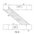
- FIGS. 10 through 12illustrate top views of alternative inductor structures formed according to the teachings of the present invention.
- FIG. 1One process for forming an inductor according to the present invention begins as shown in FIG. 1, where a plurality of insulating layers are formed over an existing integrated circuit substrate 10 , which conventionally includes a plurality of active elements. Typically, at this point in the conventional fabrication process, no metal interconnect layers have been formed for the active device; only the vias or windows for gaining access to the active device regions have been formed.
- a barrier layer 20overlies the surface of the semiconductor substrate 10 and is preferably formed of tantalum, tantalum-nitride, titanium or titanium-nitride.
- an insulating layer 22preferably one formed from a relatively low dielectric constant material is formed over the barrier layer 20 . Low dielectric silicon dioxide, black diamond and coral are suitable candidates for the insulating layer 22 .
- the relative dielectric constant for silicon dioxideis about 3.9. This a low relative dielectric constant is generally considered to be less than about 3.0.
- the low dielectric constant materialreduces inter-layer capacitance and therefore potential cross-talk between signals, although in another embodiment conventional silicon dioxide can be used.
- the barrier layer 20 and the insulating layer 22can be formed by chemical vapor deposition.
- a layer 24 overlying the insulating layer 22comprises a hard mask of silicon dioxide.
- photoresist materialis applied over the hard mask, the photoresist is patterned and then the pattern is transferred from the photoresist to the hard mask. The photoresist is removed and the etching steps are carried out using the hard mask pattern.
- This processadvantageously offers better dimensional control of the etched features.
- conventional photo resist patterning and etching stepscan be utilized. In either case, as shown in FIG. 2, a window or trench 30 is formed in the insulating layer 22 and the hard mask layer 24 , by the use of suitable etchants.
- the trench 30is circular or elliptical.
- patterning and etching stepsdo not allow formation of sharp-cornered structural shapes, and thus windows and trenches, when viewed from the top, are typically circular, elliptical, or have relatively straight edges and rounded corners between the edges.
- a barrier and seed layer 32is deposited. Typically, this is accomplished in two steps. First a barrier material is sputtered into the trench 30 . Tantalum, tantalum-nitride, titanium and titanium-nitride are candidate materials for the barrier layer. Next, a thin copper seed layer is deposited, preferably by sputtering. The seed layer is required as a starting layer for the electroplated copper. Both the barrier material and the seed material of the barrier and seed layer 32 can also be deposited by conventional chemical vapor deposition and electroplating processes. A metal-1 runner layer 34 is now formed, preferably by electroplating copper. Electroplating is especially advantageous because it can be performed at a low temperature and at a relatively low cost.
- the low temperature deposition featureis advantageous as it avoids changes in the dopant profiles in active regions of the semiconductor substrate.
- the substrateis then chemically-mechanically polished to remove the electroplated copper from all regions except within the metal-1 runner 34 .
- This process for depositing copper layers in the insulating layersis known as the damascene process. It offers superior dimensional control because it eliminates the variations introduced in a conventional metal pattern and etch process where the vias and the interconnects are formed in two separate steps. Additional details of the damascene and dual damascene process are discussed in the following references, which are hereby incorporated by reference: C. K. Hu et. al., Proceedings MRS Symposium on VLSI, vol. 5, p. 369 (1990); B. Luther et. al., Proceedings VMIC, vol. 10, p. 15 (1994); D. Edelstein, Proceedings ECS Mtg., vol. 96-2, p. 335 (1996).
- the metal-1 runner 34may be necessary to connect to underlying active device regions in the substrate.
- one end of the metal-1 runnerserves as an inductor terminal for connection to another component in the circuit.
- Thiscan be accomplished by a dual damascene process by first forming a via opening for connecting one end of the metal-1 runner to an underlying device region. The second step forms the window 30 , and the third step simultaneously fills the via opening and the trench 30 to form a conductive via and the metal- 1 runner 34 .
- the metal-1 runner 34is connected to the underlying device region.
- the conductive viacan also be formed by conventional processes and then the metal-1 runner 34 formed in electrical contact therewith.
- a four-layer stackis now formed over the metal-1 runner 34 and the adjacent regions of the layers 20 , 22 and 24 .
- a barrier layer 40preferably of titanium-nitride
- An insulating layer 42preferably having a relatively low dielectric constant is formed over the barrier layer 40 and comprises low dielectric constant silicon-dioxide, black diamond or coral.
- the use of a low dielectric constant materialis advantageous to reduce inter-layer capacitance and thus inter-layer cross-talk, but it is not required that the insulating layer 42 comprise a low-dielectric material.
- An etch stop layer 48formed of, for example, silicon-nitride, is formed over the insulating layer 42 .
- Another insulating layer 50is formed over the etch stop layer 48 .
- a hard mask layer 52is formed over the insulating layer 50 .
- conventional photoresist and masking materialcan be used in lieu of the hard-mask layer 52 .
- a masking step employing the hard mask layer 52defines the areas where via openings 60 and 62 are formed, extending downwardly to the barrier layer 40 .
- the regions of the barrier layer 40 exposed through the via openings 60 and 62are removed by etching.
- the via openings for those interconnectsare patterned and etched when the vias openings 60 and 62 are formed. It should be noted at this point that the metal-1 runner 34 as shown in FIG.
- the via opening 60and all the elements constructed above it as will be discussed below
- the via opening 62and all the elements formed above it
- a barrier and seed layer 64is deposited within the via openings 60 and 62 .
- the process and materialsare identical to those discussed in conjunction with the barrier and seed layer 32 of FIG. 3 .
- Copperis then preferably electroplated within the via openings 60 and 62 , followed by a chemical and mechanical polishing step to planarize the top surface.
- the copper regions in the lower portion of the via openings 60 and 62are referred to as conductive vias 65 and 66 .
- the copper material in the upper regions of the via openings 60 and 62is referred to as metal-2 via layers 67 and 68 .
- a multi-layer stackis formed over the existing layers, where the material of the individual layers is preferably identical to the materials used in the multi-layer stack discussed in conjunction with FIG. 4 .
- the layers formedsequentially include a barrier layer 70 , an insulating layer 72 (preferably comprising material having a low dielectric constant), an etch stop layer 74 , an insulating layer 76 (again preferably comprising a low dielectric constant material), and a hard mask layer 78 .
- Via openings 84 and 86are formed therein, using the hard mask layer 78 to pattern and etch the surface. The exposed regions of the barrier layer 70 within the via openings 84 and 86 are removed.
- a trench 100is formed in the substrate as illustrated in FIG. 8 .
- the trench 100extends downwardly to the etch stop layer 74 .
- the etching processis monitored to analyze the byproducts that are etched from the material. In this case, when the material of the etch stop 74 is detected, the etch process is terminated. As a result, the trench 100 extends downwardly only to the etch stop layer 74 . It should be noted that the trench 100 is not in the same plane as the metal-1 runner 34 .
- an end 101 of the trench 100is in the foreground of FIG. 8 and an end 102 is in the background. This orientation is clearly shown in the FIG. 10 top view. Thus it will be seen that the conductive material formed later in the trench 100 , as described below, will interconnect two successive metal-1 runners.
- a barrier and seed layer 104is deposited to limit the diffusion of the copper into the insulating layers and to provide a seed material for the subsequent copper electroplating process. It is not necessary to form a barrier layer along the bottom surface of the trench 100 , as the etch stop layer 74 serves the barrier purpose, and the plating seed layer is not required because copper will electroplate laterally from the sidewalls of the third level vias 84 and 86 . Copper is then deposited, or preferably electroplated, as illustrated in FIG. 9, filling the via openings 84 and 86 to form conductive vias 106 and 107 , metal-3 via layer 108 and 109 and a metal-3 runner 110 therebetween. The structure is then chemically-mechanically polished to remove copper from the unwanted areas and planarize the top surface.
- the metal-3 runner 108is not in the same vertical plane as the metal-1 runner 34 . Further, there are a plurality of parallel-oriented metal-1 runners 34 and metal-3 runners 110 , interconnected as shown in the top view of FIG. 10, where the interconnected structure forms a Z-shaped structure. In this embodiment, the metal-1 runner 34 is I-shaped and from above, the combination of the metal-1 and metal-3 runners 34 and 108 , resembles the letter “Z”.
- the metal-3 runner 108serves as an interconnecting structure connecting successive metal-1 runners 34 via the vertical conductive stacks 120 (comprising the conductive via 66 , the metal-2 via layer 68 , the conductive via 107 and the metal-3 via layer 109 ) and the vertical conductive stack 122 (comprising the conductive via 65 , the metal-2 via layer 67 , the conductive via 106 and the metal-3 via layer 108 ).
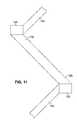
- the metal-1 and metal-3 runners 34 and 108are interconnected in an alternating zig-zag pattern to form a continuously conductive structure. See FIG. 11 .
- the metal-1 runner 34is L-shaped, with the short leg extending rearwardly to contact the metal-3 runner 108 , by way of a vertical conductive stack 120 , comprising the conductive via 66 , the metal-2 via layer 68 , the conductive via 107 and the metal-3 via layer 109 .
- the metal-3 runner 108is also L-shaped as shown, having a short leg electrically connected to the adjacent metal-1 runner 34 via an electrically conductive stack 122 , comprising the conductive via 65 , the metal-2 via layer 67 , the conductive via 106 and the metal-3 via layer 108 .
- the inventive features of the present inventioncan be applied such that the inductor spans other metal layers, for example, the bottom segment of the winding can be placed within the metal-2 layer and the top segment of the winding can be placed within the metal-4 layer or the metal-5 layer.
- the inductor according to the present inventionis formed using the damascene process, the invention is not limited to the use of this technique.
- the inductorcan also be formed using conventional metal deposition and etch steps wherein the metal layers forming the top and bottom winding segments are interconnected by vertical vias spanning at least three metal layers, i.e., at least one metal layer is not used to form either a top or a bottom winding segment.
- the multi-layer inductor formed according to the teachings of the present inventionis compatible with conventional CMOS backflow (i.e., interconnect) processing and does not require any additional masking steps during the process of fabricating the CMOS devices.
- the conductive structuresare formed of copper, the resulting conductor has relatively lower resistance than those formed with aluminum and thus a higher Q.
- a larger inductor cross-sectional arearesults from the use of metal layers at different levels of the substrate (for example, metal-1 to metal-3 or metal-3 to metal-5) and produces a higher inductance value.
- the inductoris highly integratable either on-chip with other active elements or as part of a multi-module device constructed on a common substrate.
- the use of less conductive material in the inductor structurelowers the eddy current losses. Also, the magnetic circuit lines are more concentrated due to the compact inductor structure, and thus the inductance is increased and the effect on proximate regions of the integrated circuit is reduced.
Landscapes
- Engineering & Computer Science (AREA)
- Physics & Mathematics (AREA)
- Condensed Matter Physics & Semiconductors (AREA)
- General Physics & Mathematics (AREA)
- Computer Hardware Design (AREA)
- Microelectronics & Electronic Packaging (AREA)
- Power Engineering (AREA)
- Manufacturing & Machinery (AREA)
- Internal Circuitry In Semiconductor Integrated Circuit Devices (AREA)
- Semiconductor Integrated Circuits (AREA)
Abstract
Description
Claims (2)
Priority Applications (5)
| Application Number | Priority Date | Filing Date | Title |
|---|---|---|---|
| US09/972,482US6639298B2 (en) | 2001-06-28 | 2001-10-05 | Multi-layer inductor formed in a semiconductor substrate |
| TW091121020ATW557583B (en) | 2001-10-05 | 2002-09-13 | A multi-layer inductor formed in a semiconductor substrate |
| GB0221301AGB2381130B (en) | 2001-10-05 | 2002-09-13 | A multi-layer inductor formed in a semiconductor substrate |
| KR1020020060412AKR100939648B1 (en) | 2001-10-05 | 2002-10-04 | Multilayer Inductors Formed on Semiconductor Substrates |
| JP2002291750AJP4903971B2 (en) | 2001-10-05 | 2002-10-04 | Multi-layer inductor formed on a semiconductor substrate |
Applications Claiming Priority (2)
| Application Number | Priority Date | Filing Date | Title |
|---|---|---|---|
| US30128501P | 2001-06-28 | 2001-06-28 | |
| US09/972,482US6639298B2 (en) | 2001-06-28 | 2001-10-05 | Multi-layer inductor formed in a semiconductor substrate |
Publications (2)
| Publication Number | Publication Date |
|---|---|
| US20030001231A1 US20030001231A1 (en) | 2003-01-02 |
| US6639298B2true US6639298B2 (en) | 2003-10-28 |
Family
ID=25519707
Family Applications (1)
| Application Number | Title | Priority Date | Filing Date |
|---|---|---|---|
| US09/972,482Expired - LifetimeUS6639298B2 (en) | 2001-06-28 | 2001-10-05 | Multi-layer inductor formed in a semiconductor substrate |
Country Status (5)
| Country | Link |
|---|---|
| US (1) | US6639298B2 (en) |
| JP (1) | JP4903971B2 (en) |
| KR (1) | KR100939648B1 (en) |
| GB (1) | GB2381130B (en) |
| TW (1) | TW557583B (en) |
Cited By (32)
| Publication number | Priority date | Publication date | Assignee | Title |
|---|---|---|---|---|
| US20030170989A1 (en)* | 2000-07-12 | 2003-09-11 | Philips Electronics North America Corp. | Semiconductor inductor and methods for making the same |
| US20040127036A1 (en)* | 2001-12-05 | 2004-07-01 | Micron Technology, Inc., A Corporation Of Delaware | Semiconductor device with electrically coupled spiral inductors |
| US20050104157A1 (en)* | 2003-11-19 | 2005-05-19 | International Business Machines Corporation | Tri-metal and dual-metal stacked inductors |
| US20050230837A1 (en)* | 2004-03-25 | 2005-10-20 | Infineon Technologies Ag | Semiconductor component with coreless transformer |
| US20060109464A1 (en)* | 2004-11-22 | 2006-05-25 | Akiyuki Minami | Method for detecting alignment accuracy |
| US20060158300A1 (en)* | 2005-01-20 | 2006-07-20 | Avx Corporation | High Q planar inductors and IPD applications |
| US20110001202A1 (en)* | 2007-12-31 | 2011-01-06 | Gardner Donald S | Forming inductor and transformer structures with magnetic materials using damascene processing for integrated circuits |
| US20110175193A1 (en)* | 2008-09-26 | 2011-07-21 | Rohm Co., Ltd. | Semiconductor device and semiconductor device manufacturing method |
| US20110310579A1 (en)* | 2010-06-16 | 2011-12-22 | Peter Smeys | Inductive Structure and Method of Forming the Inductive Structure with an Attached Core Structure |
| US8395455B1 (en) | 2011-10-14 | 2013-03-12 | United Microelectronics Corp. | Ring oscillator |
| US8421509B1 (en) | 2011-10-25 | 2013-04-16 | United Microelectronics Corp. | Charge pump circuit with low clock feed-through |
| US8493806B1 (en) | 2012-01-03 | 2013-07-23 | United Microelectronics Corporation | Sense-amplifier circuit of memory and calibrating method thereof |
| US8588020B2 (en) | 2011-11-16 | 2013-11-19 | United Microelectronics Corporation | Sense amplifier and method for determining values of voltages on bit-line pair |
| US8643521B1 (en) | 2012-11-28 | 2014-02-04 | United Microelectronics Corp. | Digital-to-analog converter with greater output resistance |
| US8669897B1 (en) | 2012-11-05 | 2014-03-11 | United Microelectronics Corp. | Asynchronous successive approximation register analog-to-digital converter and operating method thereof |
| US8692608B2 (en) | 2011-09-19 | 2014-04-08 | United Microelectronics Corp. | Charge pump system capable of stabilizing an output voltage |
| US8711598B1 (en) | 2012-11-21 | 2014-04-29 | United Microelectronics Corp. | Memory cell and memory cell array using the same |
| US8724404B2 (en) | 2012-10-15 | 2014-05-13 | United Microelectronics Corp. | Memory, supply voltage generation circuit, and operation method of a supply voltage generation circuit used for a memory array |
| US8859384B1 (en) | 2013-08-01 | 2014-10-14 | International Business Machines Corporation | Inductor formation with sidewall image transfer |
| US8866536B1 (en) | 2013-11-14 | 2014-10-21 | United Microelectronics Corp. | Process monitoring circuit and method |
| US8873295B2 (en) | 2012-11-27 | 2014-10-28 | United Microelectronics Corporation | Memory and operation method thereof |
| US20140354392A1 (en)* | 2013-06-04 | 2014-12-04 | International Business Machines Corporation | Metal wires of a stacked inductor |
| US8917109B2 (en) | 2013-04-03 | 2014-12-23 | United Microelectronics Corporation | Method and device for pulse width estimation |
| US8947911B1 (en) | 2013-11-07 | 2015-02-03 | United Microelectronics Corp. | Method and circuit for optimizing bit line power consumption |
| US8953401B2 (en) | 2012-12-07 | 2015-02-10 | United Microelectronics Corp. | Memory device and method for driving memory array thereof |
| US8970197B2 (en) | 2012-08-03 | 2015-03-03 | United Microelectronics Corporation | Voltage regulating circuit configured to have output voltage thereof modulated digitally |
| US9030886B2 (en) | 2012-12-07 | 2015-05-12 | United Microelectronics Corp. | Memory device and driving method thereof |
| US9030221B2 (en) | 2011-09-20 | 2015-05-12 | United Microelectronics Corporation | Circuit structure of test-key and test method thereof |
| US9105355B2 (en) | 2013-07-04 | 2015-08-11 | United Microelectronics Corporation | Memory cell array operated with multiple operation voltage |
| US9143143B2 (en) | 2014-01-13 | 2015-09-22 | United Microelectronics Corp. | VCO restart up circuit and method thereof |
| US9412734B2 (en) | 2014-12-09 | 2016-08-09 | United Microelectorincs Corp. | Structure with inductor and MIM capacitor |
| US11437174B2 (en)* | 2015-05-19 | 2022-09-06 | Shinko Electric Industries Co., Ltd. | Inductor and method of manufacturing same |
Families Citing this family (5)
| Publication number | Priority date | Publication date | Assignee | Title |
|---|---|---|---|---|
| US7262680B2 (en) | 2004-02-27 | 2007-08-28 | Illinois Institute Of Technology | Compact inductor with stacked via magnetic cores for integrated circuits |
| CN106876253B (en)* | 2017-03-10 | 2019-06-04 | 成都海威华芯科技有限公司 | A kind of acute angle metallic pattern stripping means |
| US10672704B2 (en)* | 2017-11-30 | 2020-06-02 | Taiwan Semiconductor Manufacturing Company Ltd. | Semiconductor device with polygonal inductive device |
| US10672859B2 (en)* | 2018-06-27 | 2020-06-02 | Intel Corporation | Embedded magnetic inductor |
| CN114203668A (en)* | 2020-09-02 | 2022-03-18 | 联华电子股份有限公司 | Inductance module and method for making the same |
Citations (32)
| Publication number | Priority date | Publication date | Assignee | Title |
|---|---|---|---|---|
| GB1279160A (en) | 1968-10-24 | 1972-06-28 | Texas Instruments Inc | Thin film inductors and methods of fabricating same |
| US4313152A (en) | 1979-01-12 | 1982-01-26 | U.S. Philips Corporation | Flat electric coil |
| US5095357A (en) | 1989-08-18 | 1992-03-10 | Mitsubishi Denki Kabushiki Kaisha | Inductive structures for semiconductor integrated circuits |
| US5157576A (en) | 1990-02-20 | 1992-10-20 | Tdk Corporation | Composite electric part of stacked multi-layer structure |
| US5227659A (en) | 1990-06-08 | 1993-07-13 | Trustees Of Boston University | Integrated circuit inductor |
| US5372967A (en) | 1992-01-27 | 1994-12-13 | Motorola, Inc. | Method for fabricating a vertical trench inductor |
| US5446311A (en)* | 1994-09-16 | 1995-08-29 | International Business Machines Corporation | High-Q inductors in silicon technology without expensive metalization |
| US5541442A (en) | 1994-08-31 | 1996-07-30 | International Business Machines Corporation | Integrated compact capacitor-resistor/inductor configuration |
| EP0725407A1 (en) | 1995-02-03 | 1996-08-07 | International Business Machines Corporation | Three-dimensional integrated circuit inductor |
| US5559360A (en) | 1994-12-19 | 1996-09-24 | Lucent Technologies Inc. | Inductor for high frequency circuits |
| US5610433A (en) | 1995-03-13 | 1997-03-11 | National Semiconductor Corporation | Multi-turn, multi-level IC inductor with crossovers |
| US5717243A (en) | 1996-04-24 | 1998-02-10 | Harris Corporation | Integrated circuit with an improved inductor structure and method of fabrication |
| US5736749A (en) | 1996-11-19 | 1998-04-07 | Lucent Technologies Inc. | Integrated circuit device with inductor incorporated therein |
| US5863806A (en) | 1996-11-21 | 1999-01-26 | United Microelectronics Corp. | Method of forming microcoil structure for integrated circuits |
| JPH11354330A (en)* | 1998-06-08 | 1999-12-24 | Mitsubishi Materials Corp | Laminated chip parts and its usage |
| US6008102A (en) | 1998-04-09 | 1999-12-28 | Motorola, Inc. | Method of forming a three-dimensional integrated inductor |
| US6015742A (en) | 1997-09-29 | 2000-01-18 | Lg Semicon Co., Ltd. | Method for fabricating inductor of semiconductor device |
| US6031445A (en)* | 1997-11-28 | 2000-02-29 | Stmicroelectronics S.A. | Transformer for integrated circuits |
| US6037649A (en) | 1999-04-01 | 2000-03-14 | Winbond Electronics Corp. | Three-dimension inductor structure in integrated circuit technology |
| US6057202A (en) | 1998-01-16 | 2000-05-02 | Windbond Electronics Corp. | Method for manufacturing an inductor with resonant frequency and Q value increased in semiconductor process |
| US6083802A (en) | 1998-12-31 | 2000-07-04 | Winbond Electronics Corporation | Method for forming an inductor |
| US6124624A (en) | 1997-02-28 | 2000-09-26 | Telefonaktiebolaget Lm Ericsson | Q inductor with multiple metallization levels |
| US6140197A (en) | 1999-08-30 | 2000-10-31 | Chartered Semiconductor Manufacturing Ltd. | Method of making spiral-type RF inductors having a high quality factor (Q) |
| US6160303A (en) | 1997-08-29 | 2000-12-12 | Texas Instruments Incorporated | Monolithic inductor with guard rings |
| US6166422A (en) | 1998-05-13 | 2000-12-26 | Lsi Logic Corporation | Inductor with cobalt/nickel core for integrated circuit structure with high inductance and high Q-factor |
| US6187647B1 (en) | 1999-10-12 | 2001-02-13 | Lucent Technologies Inc. | Method of manufacturing lateral high-Q inductor for semiconductor devices |
| US6240622B1 (en) | 1999-07-09 | 2001-06-05 | Micron Technology, Inc. | Integrated circuit inductors |
| US6249191B1 (en) | 1998-11-23 | 2001-06-19 | Micron Technology, Inc. | Monolithic integrated circuit oscillators, complementary metal oxide semiconductor (CMOS) voltage-controlled oscillators, integrated circuit oscillators, oscillator-forming methods, and oscillation methods |
| US6255714B1 (en) | 1999-06-22 | 2001-07-03 | Agere Systems Guardian Corporation | Integrated circuit having a micromagnetic device including a ferromagnetic core and method of manufacture therefor |
| WO2002013271A2 (en) | 2000-08-04 | 2002-02-14 | Infineon Technologies Ag | Integrated electronic circuit with at least one inductor and method for producing the same |
| US6420773B1 (en)* | 2000-10-04 | 2002-07-16 | Winbond Electronics Corp. | Multi-level spiral inductor structure having high inductance (L) and high quality factor (Q) |
| US6429504B1 (en)* | 2000-05-16 | 2002-08-06 | Tyco Electronics Corporation | Multilayer spiral inductor and integrated circuits incorporating the same |
Family Cites Families (8)
| Publication number | Priority date | Publication date | Assignee | Title |
|---|---|---|---|---|
| JPH0269971A (en)* | 1988-09-05 | 1990-03-08 | Seiko Epson Corp | Semiconductor device with built-in inductance |
| JPH02181961A (en)* | 1989-01-09 | 1990-07-16 | Nec Corp | Integrated circuit device |
| JPH04335531A (en)* | 1991-05-10 | 1992-11-24 | Mitsubishi Electric Corp | semiconductor equipment |
| US5861647A (en)* | 1996-10-02 | 1999-01-19 | National Semiconductor Corporation | VLSI capacitors and high Q VLSI inductors using metal-filled via plugs |
| JP3578644B2 (en)* | 1998-10-12 | 2004-10-20 | Necエレクトロニクス株式会社 | Semiconductor device |
| JP2000232202A (en)* | 1998-12-11 | 2000-08-22 | Matsushita Electric Ind Co Ltd | High Q inductor for high frequency |
| JP2000269418A (en)* | 1999-03-17 | 2000-09-29 | Sony Corp | Wiring structure, inductor and formation method therefor |
| KR20010075974A (en)* | 2000-01-21 | 2001-08-11 | 이서헌 | Semiconductor Integrated Inductor |
- 2001
- 2001-10-05USUS09/972,482patent/US6639298B2/ennot_activeExpired - Lifetime
- 2002
- 2002-09-13GBGB0221301Apatent/GB2381130B/ennot_activeExpired - Fee Related
- 2002-09-13TWTW091121020Apatent/TW557583B/ennot_activeIP Right Cessation
- 2002-10-04JPJP2002291750Apatent/JP4903971B2/ennot_activeExpired - Lifetime
- 2002-10-04KRKR1020020060412Apatent/KR100939648B1/ennot_activeExpired - Fee Related
Patent Citations (32)
| Publication number | Priority date | Publication date | Assignee | Title |
|---|---|---|---|---|
| GB1279160A (en) | 1968-10-24 | 1972-06-28 | Texas Instruments Inc | Thin film inductors and methods of fabricating same |
| US4313152A (en) | 1979-01-12 | 1982-01-26 | U.S. Philips Corporation | Flat electric coil |
| US5095357A (en) | 1989-08-18 | 1992-03-10 | Mitsubishi Denki Kabushiki Kaisha | Inductive structures for semiconductor integrated circuits |
| US5157576A (en) | 1990-02-20 | 1992-10-20 | Tdk Corporation | Composite electric part of stacked multi-layer structure |
| US5227659A (en) | 1990-06-08 | 1993-07-13 | Trustees Of Boston University | Integrated circuit inductor |
| US5372967A (en) | 1992-01-27 | 1994-12-13 | Motorola, Inc. | Method for fabricating a vertical trench inductor |
| US5541442A (en) | 1994-08-31 | 1996-07-30 | International Business Machines Corporation | Integrated compact capacitor-resistor/inductor configuration |
| US5446311A (en)* | 1994-09-16 | 1995-08-29 | International Business Machines Corporation | High-Q inductors in silicon technology without expensive metalization |
| US5559360A (en) | 1994-12-19 | 1996-09-24 | Lucent Technologies Inc. | Inductor for high frequency circuits |
| EP0725407A1 (en) | 1995-02-03 | 1996-08-07 | International Business Machines Corporation | Three-dimensional integrated circuit inductor |
| US5610433A (en) | 1995-03-13 | 1997-03-11 | National Semiconductor Corporation | Multi-turn, multi-level IC inductor with crossovers |
| US5717243A (en) | 1996-04-24 | 1998-02-10 | Harris Corporation | Integrated circuit with an improved inductor structure and method of fabrication |
| US5736749A (en) | 1996-11-19 | 1998-04-07 | Lucent Technologies Inc. | Integrated circuit device with inductor incorporated therein |
| US5863806A (en) | 1996-11-21 | 1999-01-26 | United Microelectronics Corp. | Method of forming microcoil structure for integrated circuits |
| US6124624A (en) | 1997-02-28 | 2000-09-26 | Telefonaktiebolaget Lm Ericsson | Q inductor with multiple metallization levels |
| US6160303A (en) | 1997-08-29 | 2000-12-12 | Texas Instruments Incorporated | Monolithic inductor with guard rings |
| US6015742A (en) | 1997-09-29 | 2000-01-18 | Lg Semicon Co., Ltd. | Method for fabricating inductor of semiconductor device |
| US6031445A (en)* | 1997-11-28 | 2000-02-29 | Stmicroelectronics S.A. | Transformer for integrated circuits |
| US6057202A (en) | 1998-01-16 | 2000-05-02 | Windbond Electronics Corp. | Method for manufacturing an inductor with resonant frequency and Q value increased in semiconductor process |
| US6008102A (en) | 1998-04-09 | 1999-12-28 | Motorola, Inc. | Method of forming a three-dimensional integrated inductor |
| US6166422A (en) | 1998-05-13 | 2000-12-26 | Lsi Logic Corporation | Inductor with cobalt/nickel core for integrated circuit structure with high inductance and high Q-factor |
| JPH11354330A (en)* | 1998-06-08 | 1999-12-24 | Mitsubishi Materials Corp | Laminated chip parts and its usage |
| US6249191B1 (en) | 1998-11-23 | 2001-06-19 | Micron Technology, Inc. | Monolithic integrated circuit oscillators, complementary metal oxide semiconductor (CMOS) voltage-controlled oscillators, integrated circuit oscillators, oscillator-forming methods, and oscillation methods |
| US6083802A (en) | 1998-12-31 | 2000-07-04 | Winbond Electronics Corporation | Method for forming an inductor |
| US6037649A (en) | 1999-04-01 | 2000-03-14 | Winbond Electronics Corp. | Three-dimension inductor structure in integrated circuit technology |
| US6255714B1 (en) | 1999-06-22 | 2001-07-03 | Agere Systems Guardian Corporation | Integrated circuit having a micromagnetic device including a ferromagnetic core and method of manufacture therefor |
| US6240622B1 (en) | 1999-07-09 | 2001-06-05 | Micron Technology, Inc. | Integrated circuit inductors |
| US6140197A (en) | 1999-08-30 | 2000-10-31 | Chartered Semiconductor Manufacturing Ltd. | Method of making spiral-type RF inductors having a high quality factor (Q) |
| US6187647B1 (en) | 1999-10-12 | 2001-02-13 | Lucent Technologies Inc. | Method of manufacturing lateral high-Q inductor for semiconductor devices |
| US6429504B1 (en)* | 2000-05-16 | 2002-08-06 | Tyco Electronics Corporation | Multilayer spiral inductor and integrated circuits incorporating the same |
| WO2002013271A2 (en) | 2000-08-04 | 2002-02-14 | Infineon Technologies Ag | Integrated electronic circuit with at least one inductor and method for producing the same |
| US6420773B1 (en)* | 2000-10-04 | 2002-07-16 | Winbond Electronics Corp. | Multi-level spiral inductor structure having high inductance (L) and high quality factor (Q) |
Non-Patent Citations (1)
| Title |
|---|
| Niknejad, Ali M. and Meyer, Robert G.; "Design, Simulation and Applications of Inductors and Transformers for Si RF ICs"; Kluwer Academic Publishers, Boston/Dordrecht/London; pp. 22-31. 2000. |
Cited By (45)
| Publication number | Priority date | Publication date | Assignee | Title |
|---|---|---|---|---|
| US6717232B2 (en)* | 2000-07-12 | 2004-04-06 | Koninklijke Philips Electronics N.V. | Semiconductor inductor and methods for making the same |
| US20030170989A1 (en)* | 2000-07-12 | 2003-09-11 | Philips Electronics North America Corp. | Semiconductor inductor and methods for making the same |
| US20040127036A1 (en)* | 2001-12-05 | 2004-07-01 | Micron Technology, Inc., A Corporation Of Delaware | Semiconductor device with electrically coupled spiral inductors |
| US7023316B2 (en)* | 2001-12-05 | 2006-04-04 | Micron Technology, Inc. | Semiconductor device with electrically coupled spiral inductors |
| US7129561B2 (en)* | 2003-11-19 | 2006-10-31 | International Business Machines Corporation | Tri-metal and dual-metal stacked inductors |
| US20050104157A1 (en)* | 2003-11-19 | 2005-05-19 | International Business Machines Corporation | Tri-metal and dual-metal stacked inductors |
| US20050230837A1 (en)* | 2004-03-25 | 2005-10-20 | Infineon Technologies Ag | Semiconductor component with coreless transformer |
| US7417301B2 (en)* | 2004-03-25 | 2008-08-26 | Infineon Technologies Ag | Semiconductor component with coreless transformer |
| US20060109464A1 (en)* | 2004-11-22 | 2006-05-25 | Akiyuki Minami | Method for detecting alignment accuracy |
| US20060158300A1 (en)* | 2005-01-20 | 2006-07-20 | Avx Corporation | High Q planar inductors and IPD applications |
| US7714688B2 (en) | 2005-01-20 | 2010-05-11 | Avx Corporation | High Q planar inductors and IPD applications |
| US20110001202A1 (en)* | 2007-12-31 | 2011-01-06 | Gardner Donald S | Forming inductor and transformer structures with magnetic materials using damascene processing for integrated circuits |
| US8513750B2 (en)* | 2007-12-31 | 2013-08-20 | Intel Corporation | Forming inductor and transformer structures with magnetic materials using damascene processing for integrated circuits |
| US20110175193A1 (en)* | 2008-09-26 | 2011-07-21 | Rohm Co., Ltd. | Semiconductor device and semiconductor device manufacturing method |
| CN102165576A (en)* | 2008-09-26 | 2011-08-24 | 罗姆股份有限公司 | Semiconductor device and method for manufacturing semiconductor device |
| US9735110B2 (en) | 2008-09-26 | 2017-08-15 | Rohm Co., Ltd. | Semiconductor device and semiconductor device manufacturing method |
| CN102165576B (en)* | 2008-09-26 | 2013-12-25 | 罗姆股份有限公司 | Semiconductor device and method for manufacturing semiconductor device |
| US8410576B2 (en)* | 2010-06-16 | 2013-04-02 | National Semiconductor Corporation | Inductive structure and method of forming the inductive structure with an attached core structure |
| US20110310579A1 (en)* | 2010-06-16 | 2011-12-22 | Peter Smeys | Inductive Structure and Method of Forming the Inductive Structure with an Attached Core Structure |
| US8692608B2 (en) | 2011-09-19 | 2014-04-08 | United Microelectronics Corp. | Charge pump system capable of stabilizing an output voltage |
| US9030221B2 (en) | 2011-09-20 | 2015-05-12 | United Microelectronics Corporation | Circuit structure of test-key and test method thereof |
| US8395455B1 (en) | 2011-10-14 | 2013-03-12 | United Microelectronics Corp. | Ring oscillator |
| US8421509B1 (en) | 2011-10-25 | 2013-04-16 | United Microelectronics Corp. | Charge pump circuit with low clock feed-through |
| US8588020B2 (en) | 2011-11-16 | 2013-11-19 | United Microelectronics Corporation | Sense amplifier and method for determining values of voltages on bit-line pair |
| US8493806B1 (en) | 2012-01-03 | 2013-07-23 | United Microelectronics Corporation | Sense-amplifier circuit of memory and calibrating method thereof |
| US8970197B2 (en) | 2012-08-03 | 2015-03-03 | United Microelectronics Corporation | Voltage regulating circuit configured to have output voltage thereof modulated digitally |
| US8724404B2 (en) | 2012-10-15 | 2014-05-13 | United Microelectronics Corp. | Memory, supply voltage generation circuit, and operation method of a supply voltage generation circuit used for a memory array |
| US8767485B1 (en) | 2012-10-15 | 2014-07-01 | United Microelectronics Corp. | Operation method of a supply voltage generation circuit used for a memory array |
| US8804440B1 (en) | 2012-10-15 | 2014-08-12 | United Microelectronics Corporation | Memory for a voltage regulator circuit |
| US8669897B1 (en) | 2012-11-05 | 2014-03-11 | United Microelectronics Corp. | Asynchronous successive approximation register analog-to-digital converter and operating method thereof |
| US8711598B1 (en) | 2012-11-21 | 2014-04-29 | United Microelectronics Corp. | Memory cell and memory cell array using the same |
| US8873295B2 (en) | 2012-11-27 | 2014-10-28 | United Microelectronics Corporation | Memory and operation method thereof |
| US8643521B1 (en) | 2012-11-28 | 2014-02-04 | United Microelectronics Corp. | Digital-to-analog converter with greater output resistance |
| US8953401B2 (en) | 2012-12-07 | 2015-02-10 | United Microelectronics Corp. | Memory device and method for driving memory array thereof |
| US9030886B2 (en) | 2012-12-07 | 2015-05-12 | United Microelectronics Corp. | Memory device and driving method thereof |
| US8917109B2 (en) | 2013-04-03 | 2014-12-23 | United Microelectronics Corporation | Method and device for pulse width estimation |
| US20140354392A1 (en)* | 2013-06-04 | 2014-12-04 | International Business Machines Corporation | Metal wires of a stacked inductor |
| US9577023B2 (en)* | 2013-06-04 | 2017-02-21 | Globalfoundries Inc. | Metal wires of a stacked inductor |
| US9105355B2 (en) | 2013-07-04 | 2015-08-11 | United Microelectronics Corporation | Memory cell array operated with multiple operation voltage |
| US8859384B1 (en) | 2013-08-01 | 2014-10-14 | International Business Machines Corporation | Inductor formation with sidewall image transfer |
| US8947911B1 (en) | 2013-11-07 | 2015-02-03 | United Microelectronics Corp. | Method and circuit for optimizing bit line power consumption |
| US8866536B1 (en) | 2013-11-14 | 2014-10-21 | United Microelectronics Corp. | Process monitoring circuit and method |
| US9143143B2 (en) | 2014-01-13 | 2015-09-22 | United Microelectronics Corp. | VCO restart up circuit and method thereof |
| US9412734B2 (en) | 2014-12-09 | 2016-08-09 | United Microelectorincs Corp. | Structure with inductor and MIM capacitor |
| US11437174B2 (en)* | 2015-05-19 | 2022-09-06 | Shinko Electric Industries Co., Ltd. | Inductor and method of manufacturing same |
Also Published As
| Publication number | Publication date |
|---|---|
| KR100939648B1 (en) | 2010-02-03 |
| JP2003179151A (en) | 2003-06-27 |
| US20030001231A1 (en) | 2003-01-02 |
| KR20030029491A (en) | 2003-04-14 |
| TW557583B (en) | 2003-10-11 |
| GB2381130A (en) | 2003-04-23 |
| GB0221301D0 (en) | 2002-10-23 |
| GB2381130B (en) | 2006-02-01 |
| JP4903971B2 (en) | 2012-03-28 |
Similar Documents
| Publication | Publication Date | Title |
|---|---|---|
| US6639298B2 (en) | Multi-layer inductor formed in a semiconductor substrate | |
| US6667536B2 (en) | Thin film multi-layer high Q transformer formed in a semiconductor substrate | |
| US7436281B2 (en) | Method to improve inductance with a high-permeability slotted plate core in an integrated circuit | |
| US6717232B2 (en) | Semiconductor inductor and methods for making the same | |
| US7709905B2 (en) | Dual damascene wiring and method | |
| US6426249B1 (en) | Buried metal dual damascene plate capacitor | |
| KR100773256B1 (en) | Stacked structure for parallel capacitors and method of fabrication | |
| US7381607B2 (en) | Method of forming a spiral inductor in a semiconductor substrate | |
| US7405643B2 (en) | Inductor and method of forming the same | |
| US20060192647A1 (en) | Inductor formed in an integrated circuit | |
| JPH09162354A (en) | Integrated inductor structure and its manufacture | |
| EP1267391A1 (en) | A method to fabricate RF inductors with minimum area | |
| CN100536109C (en) | Method and structure for manufacturing high-capacitance capacitor by using copper | |
| US8004061B1 (en) | Conductive trace with reduced RF impedance resulting from the skin effect | |
| WO2003058715A1 (en) | Integrated passive devices formed by demascene processing | |
| US7223680B1 (en) | Method of forming a dual damascene metal trace with reduced RF impedance resulting from the skin effect |
Legal Events
| Date | Code | Title | Description |
|---|---|---|---|
| AS | Assignment | Owner name:AGERE SYSTEMS GUARDIAN CORP., FLORIDA Free format text:ASSIGNMENT OF ASSIGNORS INTEREST;ASSIGNORS:CHAUDHRY, SAMIR;LAYMAN, PAUL ARTHUR;THOMSON, J. ROSS;AND OTHERS;REEL/FRAME:012256/0167 Effective date:20011003 | |
| STCF | Information on status: patent grant | Free format text:PATENTED CASE | |
| FPAY | Fee payment | Year of fee payment:4 | |
| AS | Assignment | Owner name:AGERE SYSTEMS INC., PENNSYLVANIA Free format text:MERGER;ASSIGNOR:AGERE SYSTEMS GUARDIAN CORP.;REEL/FRAME:024990/0837 Effective date:20020831 | |
| FPAY | Fee payment | Year of fee payment:8 | |
| AS | Assignment | Owner name:DEUTSCHE BANK AG NEW YORK BRANCH, AS COLLATERAL AG Free format text:PATENT SECURITY AGREEMENT;ASSIGNORS:LSI CORPORATION;AGERE SYSTEMS LLC;REEL/FRAME:032856/0031 Effective date:20140506 | |
| FPAY | Fee payment | Year of fee payment:12 | |
| AS | Assignment | Owner name:AVAGO TECHNOLOGIES GENERAL IP (SINGAPORE) PTE. LTD Free format text:ASSIGNMENT OF ASSIGNORS INTEREST;ASSIGNOR:AGERE SYSTEMS LLC;REEL/FRAME:035365/0634 Effective date:20140804 | |
| AS | Assignment | Owner name:AGERE SYSTEMS LLC, PENNSYLVANIA Free format text:TERMINATION AND RELEASE OF SECURITY INTEREST IN PATENT RIGHTS (RELEASES RF 032856-0031);ASSIGNOR:DEUTSCHE BANK AG NEW YORK BRANCH, AS COLLATERAL AGENT;REEL/FRAME:037684/0039 Effective date:20160201 Owner name:LSI CORPORATION, CALIFORNIA Free format text:TERMINATION AND RELEASE OF SECURITY INTEREST IN PATENT RIGHTS (RELEASES RF 032856-0031);ASSIGNOR:DEUTSCHE BANK AG NEW YORK BRANCH, AS COLLATERAL AGENT;REEL/FRAME:037684/0039 Effective date:20160201 | |
| AS | Assignment | Owner name:BANK OF AMERICA, N.A., AS COLLATERAL AGENT, NORTH CAROLINA Free format text:PATENT SECURITY AGREEMENT;ASSIGNOR:AVAGO TECHNOLOGIES GENERAL IP (SINGAPORE) PTE. LTD.;REEL/FRAME:037808/0001 Effective date:20160201 Owner name:BANK OF AMERICA, N.A., AS COLLATERAL AGENT, NORTH Free format text:PATENT SECURITY AGREEMENT;ASSIGNOR:AVAGO TECHNOLOGIES GENERAL IP (SINGAPORE) PTE. LTD.;REEL/FRAME:037808/0001 Effective date:20160201 | |
| AS | Assignment | Owner name:AVAGO TECHNOLOGIES GENERAL IP (SINGAPORE) PTE. LTD., SINGAPORE Free format text:TERMINATION AND RELEASE OF SECURITY INTEREST IN PATENTS;ASSIGNOR:BANK OF AMERICA, N.A., AS COLLATERAL AGENT;REEL/FRAME:041710/0001 Effective date:20170119 Owner name:AVAGO TECHNOLOGIES GENERAL IP (SINGAPORE) PTE. LTD Free format text:TERMINATION AND RELEASE OF SECURITY INTEREST IN PATENTS;ASSIGNOR:BANK OF AMERICA, N.A., AS COLLATERAL AGENT;REEL/FRAME:041710/0001 Effective date:20170119 | |
| AS | Assignment | Owner name:BELL SEMICONDUCTOR, LLC, ILLINOIS Free format text:ASSIGNMENT OF ASSIGNORS INTEREST;ASSIGNORS:AVAGO TECHNOLOGIES GENERAL IP (SINGAPORE) PTE. LTD.;BROADCOM CORPORATION;REEL/FRAME:044886/0608 Effective date:20171208 | |
| AS | Assignment | Owner name:CORTLAND CAPITAL MARKET SERVICES LLC, AS COLLATERA Free format text:SECURITY INTEREST;ASSIGNORS:HILCO PATENT ACQUISITION 56, LLC;BELL SEMICONDUCTOR, LLC;BELL NORTHERN RESEARCH, LLC;REEL/FRAME:045216/0020 Effective date:20180124 | |
| AS | Assignment | Owner name:BELL NORTHERN RESEARCH, LLC, ILLINOIS Free format text:RELEASE BY SECURED PARTY;ASSIGNOR:CORTLAND CAPITAL MARKET SERVICES LLC;REEL/FRAME:059720/0719 Effective date:20220401 Owner name:BELL SEMICONDUCTOR, LLC, ILLINOIS Free format text:RELEASE BY SECURED PARTY;ASSIGNOR:CORTLAND CAPITAL MARKET SERVICES LLC;REEL/FRAME:059720/0719 Effective date:20220401 Owner name:HILCO PATENT ACQUISITION 56, LLC, ILLINOIS Free format text:RELEASE BY SECURED PARTY;ASSIGNOR:CORTLAND CAPITAL MARKET SERVICES LLC;REEL/FRAME:059720/0719 Effective date:20220401 |