US6638478B1 - Synchronized volumetric fluid balancing systems and methods - Google Patents
Synchronized volumetric fluid balancing systems and methodsDownload PDFInfo
- Publication number
- US6638478B1 US6638478B1US09/513,911US51391100AUS6638478B1US 6638478 B1US6638478 B1US 6638478B1US 51391100 AUS51391100 AUS 51391100AUS 6638478 B1US6638478 B1US 6638478B1
- Authority
- US
- United States
- Prior art keywords
- fluid
- compartment
- chamber
- volume
- ingoing
- Prior art date
- Legal status (The legal status is an assumption and is not a legal conclusion. Google has not performed a legal analysis and makes no representation as to the accuracy of the status listed.)
- Expired - Lifetime
Links
Images


Classifications
- A—HUMAN NECESSITIES
- A61—MEDICAL OR VETERINARY SCIENCE; HYGIENE
- A61M—DEVICES FOR INTRODUCING MEDIA INTO, OR ONTO, THE BODY; DEVICES FOR TRANSDUCING BODY MEDIA OR FOR TAKING MEDIA FROM THE BODY; DEVICES FOR PRODUCING OR ENDING SLEEP OR STUPOR
- A61M1/00—Suction or pumping devices for medical purposes; Devices for carrying-off, for treatment of, or for carrying-over, body-liquids; Drainage systems
- A61M1/34—Filtering material out of the blood by passing it through a membrane, i.e. hemofiltration or diafiltration
- A61M1/342—Adding solutions to the blood, e.g. substitution solutions
- A—HUMAN NECESSITIES
- A61—MEDICAL OR VETERINARY SCIENCE; HYGIENE
- A61M—DEVICES FOR INTRODUCING MEDIA INTO, OR ONTO, THE BODY; DEVICES FOR TRANSDUCING BODY MEDIA OR FOR TAKING MEDIA FROM THE BODY; DEVICES FOR PRODUCING OR ENDING SLEEP OR STUPOR
- A61M1/00—Suction or pumping devices for medical purposes; Devices for carrying-off, for treatment of, or for carrying-over, body-liquids; Drainage systems
- A61M1/14—Dialysis systems; Artificial kidneys; Blood oxygenators ; Reciprocating systems for treatment of body fluids, e.g. single needle systems for hemofiltration or pheresis
- A61M1/16—Dialysis systems; Artificial kidneys; Blood oxygenators ; Reciprocating systems for treatment of body fluids, e.g. single needle systems for hemofiltration or pheresis with membranes
- A61M1/1621—Constructional aspects thereof
- A61M1/1635—Constructional aspects thereof with volume chamber balancing devices between used and fresh dialysis fluid
- A61M1/1639—Constructional aspects thereof with volume chamber balancing devices between used and fresh dialysis fluid linked by membranes
- A—HUMAN NECESSITIES
- A61—MEDICAL OR VETERINARY SCIENCE; HYGIENE
- A61M—DEVICES FOR INTRODUCING MEDIA INTO, OR ONTO, THE BODY; DEVICES FOR TRANSDUCING BODY MEDIA OR FOR TAKING MEDIA FROM THE BODY; DEVICES FOR PRODUCING OR ENDING SLEEP OR STUPOR
- A61M1/00—Suction or pumping devices for medical purposes; Devices for carrying-off, for treatment of, or for carrying-over, body-liquids; Drainage systems
- A61M1/34—Filtering material out of the blood by passing it through a membrane, i.e. hemofiltration or diafiltration
- A61M1/3403—Regulation parameters
- A—HUMAN NECESSITIES
- A61—MEDICAL OR VETERINARY SCIENCE; HYGIENE
- A61M—DEVICES FOR INTRODUCING MEDIA INTO, OR ONTO, THE BODY; DEVICES FOR TRANSDUCING BODY MEDIA OR FOR TAKING MEDIA FROM THE BODY; DEVICES FOR PRODUCING OR ENDING SLEEP OR STUPOR
- A61M1/00—Suction or pumping devices for medical purposes; Devices for carrying-off, for treatment of, or for carrying-over, body-liquids; Drainage systems
- A61M1/34—Filtering material out of the blood by passing it through a membrane, i.e. hemofiltration or diafiltration
- A61M1/342—Adding solutions to the blood, e.g. substitution solutions
- A61M1/3441—Substitution rate control as a function of the ultrafiltration rate
- A61M1/3444—Substitution rate control as a function of the ultrafiltration rate in which the collected ultra-filtrate expels an equal volume of substitution fluid from a reservoir
- A—HUMAN NECESSITIES
- A61—MEDICAL OR VETERINARY SCIENCE; HYGIENE
- A61M—DEVICES FOR INTRODUCING MEDIA INTO, OR ONTO, THE BODY; DEVICES FOR TRANSDUCING BODY MEDIA OR FOR TAKING MEDIA FROM THE BODY; DEVICES FOR PRODUCING OR ENDING SLEEP OR STUPOR
- A61M1/00—Suction or pumping devices for medical purposes; Devices for carrying-off, for treatment of, or for carrying-over, body-liquids; Drainage systems
- A61M1/34—Filtering material out of the blood by passing it through a membrane, i.e. hemofiltration or diafiltration
- A61M1/342—Adding solutions to the blood, e.g. substitution solutions
- A61M1/3441—Substitution rate control as a function of the ultrafiltration rate
- A61M1/3448—Substitution rate control as a function of the ultrafiltration rate by mechanically linked pumps in both ultra-filtrate and substitution flow line
- A—HUMAN NECESSITIES
- A61—MEDICAL OR VETERINARY SCIENCE; HYGIENE
- A61M—DEVICES FOR INTRODUCING MEDIA INTO, OR ONTO, THE BODY; DEVICES FOR TRANSDUCING BODY MEDIA OR FOR TAKING MEDIA FROM THE BODY; DEVICES FOR PRODUCING OR ENDING SLEEP OR STUPOR
- A61M1/00—Suction or pumping devices for medical purposes; Devices for carrying-off, for treatment of, or for carrying-over, body-liquids; Drainage systems
- A61M1/34—Filtering material out of the blood by passing it through a membrane, i.e. hemofiltration or diafiltration
- A61M1/342—Adding solutions to the blood, e.g. substitution solutions
- A61M1/3455—Substitution fluids
- A61M1/3458—Substitution fluids having electrolytes not present in the dialysate
- A—HUMAN NECESSITIES
- A61—MEDICAL OR VETERINARY SCIENCE; HYGIENE
- A61M—DEVICES FOR INTRODUCING MEDIA INTO, OR ONTO, THE BODY; DEVICES FOR TRANSDUCING BODY MEDIA OR FOR TAKING MEDIA FROM THE BODY; DEVICES FOR PRODUCING OR ENDING SLEEP OR STUPOR
- A61M1/00—Suction or pumping devices for medical purposes; Devices for carrying-off, for treatment of, or for carrying-over, body-liquids; Drainage systems
- A61M1/36—Other treatment of blood in a by-pass of the natural circulatory system, e.g. temperature adaptation, irradiation ; Extra-corporeal blood circuits
- A61M1/3607—Regulation parameters
- A61M1/3609—Physical characteristics of the blood, e.g. haematocrit, urea
- A61M1/361—Physical characteristics of the blood, e.g. haematocrit, urea before treatment
- A—HUMAN NECESSITIES
- A61—MEDICAL OR VETERINARY SCIENCE; HYGIENE
- A61M—DEVICES FOR INTRODUCING MEDIA INTO, OR ONTO, THE BODY; DEVICES FOR TRANSDUCING BODY MEDIA OR FOR TAKING MEDIA FROM THE BODY; DEVICES FOR PRODUCING OR ENDING SLEEP OR STUPOR
- A61M1/00—Suction or pumping devices for medical purposes; Devices for carrying-off, for treatment of, or for carrying-over, body-liquids; Drainage systems
- A61M1/36—Other treatment of blood in a by-pass of the natural circulatory system, e.g. temperature adaptation, irradiation ; Extra-corporeal blood circuits
- A61M1/3607—Regulation parameters
- A61M1/3609—Physical characteristics of the blood, e.g. haematocrit, urea
- A61M1/3612—Physical characteristics of the blood, e.g. haematocrit, urea after treatment
- A—HUMAN NECESSITIES
- A61—MEDICAL OR VETERINARY SCIENCE; HYGIENE
- A61M—DEVICES FOR INTRODUCING MEDIA INTO, OR ONTO, THE BODY; DEVICES FOR TRANSDUCING BODY MEDIA OR FOR TAKING MEDIA FROM THE BODY; DEVICES FOR PRODUCING OR ENDING SLEEP OR STUPOR
- A61M1/00—Suction or pumping devices for medical purposes; Devices for carrying-off, for treatment of, or for carrying-over, body-liquids; Drainage systems
- A61M1/36—Other treatment of blood in a by-pass of the natural circulatory system, e.g. temperature adaptation, irradiation ; Extra-corporeal blood circuits
- A61M1/3621—Extra-corporeal blood circuits
- A61M1/3622—Extra-corporeal blood circuits with a cassette forming partially or totally the blood circuit
- A61M1/36224—Extra-corporeal blood circuits with a cassette forming partially or totally the blood circuit with sensing means or components thereof
- A—HUMAN NECESSITIES
- A61—MEDICAL OR VETERINARY SCIENCE; HYGIENE
- A61M—DEVICES FOR INTRODUCING MEDIA INTO, OR ONTO, THE BODY; DEVICES FOR TRANSDUCING BODY MEDIA OR FOR TAKING MEDIA FROM THE BODY; DEVICES FOR PRODUCING OR ENDING SLEEP OR STUPOR
- A61M1/00—Suction or pumping devices for medical purposes; Devices for carrying-off, for treatment of, or for carrying-over, body-liquids; Drainage systems
- A61M1/36—Other treatment of blood in a by-pass of the natural circulatory system, e.g. temperature adaptation, irradiation ; Extra-corporeal blood circuits
- A61M1/3621—Extra-corporeal blood circuits
- A61M1/3622—Extra-corporeal blood circuits with a cassette forming partially or totally the blood circuit
- A61M1/36225—Extra-corporeal blood circuits with a cassette forming partially or totally the blood circuit with blood pumping means or components thereof
- A—HUMAN NECESSITIES
- A61—MEDICAL OR VETERINARY SCIENCE; HYGIENE
- A61M—DEVICES FOR INTRODUCING MEDIA INTO, OR ONTO, THE BODY; DEVICES FOR TRANSDUCING BODY MEDIA OR FOR TAKING MEDIA FROM THE BODY; DEVICES FOR PRODUCING OR ENDING SLEEP OR STUPOR
- A61M1/00—Suction or pumping devices for medical purposes; Devices for carrying-off, for treatment of, or for carrying-over, body-liquids; Drainage systems
- A61M1/36—Other treatment of blood in a by-pass of the natural circulatory system, e.g. temperature adaptation, irradiation ; Extra-corporeal blood circuits
- A61M1/3621—Extra-corporeal blood circuits
- A61M1/3622—Extra-corporeal blood circuits with a cassette forming partially or totally the blood circuit
- A61M1/36226—Constructional details of cassettes, e.g. specific details on material or shape
- A—HUMAN NECESSITIES
- A61—MEDICAL OR VETERINARY SCIENCE; HYGIENE
- A61M—DEVICES FOR INTRODUCING MEDIA INTO, OR ONTO, THE BODY; DEVICES FOR TRANSDUCING BODY MEDIA OR FOR TAKING MEDIA FROM THE BODY; DEVICES FOR PRODUCING OR ENDING SLEEP OR STUPOR
- A61M1/00—Suction or pumping devices for medical purposes; Devices for carrying-off, for treatment of, or for carrying-over, body-liquids; Drainage systems
- A61M1/36—Other treatment of blood in a by-pass of the natural circulatory system, e.g. temperature adaptation, irradiation ; Extra-corporeal blood circuits
- A61M1/3621—Extra-corporeal blood circuits
- A61M1/3643—Priming, rinsing before or after use
- A61M1/3644—Mode of operation
- A61M1/3646—Expelling the residual body fluid after use, e.g. back to the body
- A—HUMAN NECESSITIES
- A61—MEDICAL OR VETERINARY SCIENCE; HYGIENE
- A61M—DEVICES FOR INTRODUCING MEDIA INTO, OR ONTO, THE BODY; DEVICES FOR TRANSDUCING BODY MEDIA OR FOR TAKING MEDIA FROM THE BODY; DEVICES FOR PRODUCING OR ENDING SLEEP OR STUPOR
- A61M1/00—Suction or pumping devices for medical purposes; Devices for carrying-off, for treatment of, or for carrying-over, body-liquids; Drainage systems
- A61M1/36—Other treatment of blood in a by-pass of the natural circulatory system, e.g. temperature adaptation, irradiation ; Extra-corporeal blood circuits
- A61M1/3621—Extra-corporeal blood circuits
- A61M1/367—Circuit parts not covered by the preceding subgroups of group A61M1/3621
- A—HUMAN NECESSITIES
- A61—MEDICAL OR VETERINARY SCIENCE; HYGIENE
- A61M—DEVICES FOR INTRODUCING MEDIA INTO, OR ONTO, THE BODY; DEVICES FOR TRANSDUCING BODY MEDIA OR FOR TAKING MEDIA FROM THE BODY; DEVICES FOR PRODUCING OR ENDING SLEEP OR STUPOR
- A61M39/00—Tubes, tube connectors, tube couplings, valves, access sites or the like, specially adapted for medical use
- A61M39/02—Access sites
- A61M39/0208—Subcutaneous access sites for injecting or removing fluids
- A—HUMAN NECESSITIES
- A61—MEDICAL OR VETERINARY SCIENCE; HYGIENE
- A61M—DEVICES FOR INTRODUCING MEDIA INTO, OR ONTO, THE BODY; DEVICES FOR TRANSDUCING BODY MEDIA OR FOR TAKING MEDIA FROM THE BODY; DEVICES FOR PRODUCING OR ENDING SLEEP OR STUPOR
- A61M1/00—Suction or pumping devices for medical purposes; Devices for carrying-off, for treatment of, or for carrying-over, body-liquids; Drainage systems
- A61M1/34—Filtering material out of the blood by passing it through a membrane, i.e. hemofiltration or diafiltration
- A61M1/3401—Cassettes therefor
- A—HUMAN NECESSITIES
- A61—MEDICAL OR VETERINARY SCIENCE; HYGIENE
- A61M—DEVICES FOR INTRODUCING MEDIA INTO, OR ONTO, THE BODY; DEVICES FOR TRANSDUCING BODY MEDIA OR FOR TAKING MEDIA FROM THE BODY; DEVICES FOR PRODUCING OR ENDING SLEEP OR STUPOR
- A61M1/00—Suction or pumping devices for medical purposes; Devices for carrying-off, for treatment of, or for carrying-over, body-liquids; Drainage systems
- A61M1/36—Other treatment of blood in a by-pass of the natural circulatory system, e.g. temperature adaptation, irradiation ; Extra-corporeal blood circuits
- A61M1/3621—Extra-corporeal blood circuits
- A61M1/3622—Extra-corporeal blood circuits with a cassette forming partially or totally the blood circuit
- A61M1/36222—Details related to the interface between cassette and machine
- A61M1/362223—Details related to the interface between cassette and machine the interface being evacuated interfaces to enhance contact
- A—HUMAN NECESSITIES
- A61—MEDICAL OR VETERINARY SCIENCE; HYGIENE
- A61M—DEVICES FOR INTRODUCING MEDIA INTO, OR ONTO, THE BODY; DEVICES FOR TRANSDUCING BODY MEDIA OR FOR TAKING MEDIA FROM THE BODY; DEVICES FOR PRODUCING OR ENDING SLEEP OR STUPOR
- A61M1/00—Suction or pumping devices for medical purposes; Devices for carrying-off, for treatment of, or for carrying-over, body-liquids; Drainage systems
- A61M1/36—Other treatment of blood in a by-pass of the natural circulatory system, e.g. temperature adaptation, irradiation ; Extra-corporeal blood circuits
- A61M1/3621—Extra-corporeal blood circuits
- A61M1/3622—Extra-corporeal blood circuits with a cassette forming partially or totally the blood circuit
- A61M1/36226—Constructional details of cassettes, e.g. specific details on material or shape
- A61M1/362262—Details of incorporated reservoirs
- A—HUMAN NECESSITIES
- A61—MEDICAL OR VETERINARY SCIENCE; HYGIENE
- A61M—DEVICES FOR INTRODUCING MEDIA INTO, OR ONTO, THE BODY; DEVICES FOR TRANSDUCING BODY MEDIA OR FOR TAKING MEDIA FROM THE BODY; DEVICES FOR PRODUCING OR ENDING SLEEP OR STUPOR
- A61M1/00—Suction or pumping devices for medical purposes; Devices for carrying-off, for treatment of, or for carrying-over, body-liquids; Drainage systems
- A61M1/36—Other treatment of blood in a by-pass of the natural circulatory system, e.g. temperature adaptation, irradiation ; Extra-corporeal blood circuits
- A61M1/3621—Extra-corporeal blood circuits
- A61M1/3622—Extra-corporeal blood circuits with a cassette forming partially or totally the blood circuit
- A61M1/36226—Constructional details of cassettes, e.g. specific details on material or shape
- A61M1/362265—Details of valves
- A—HUMAN NECESSITIES
- A61—MEDICAL OR VETERINARY SCIENCE; HYGIENE
- A61M—DEVICES FOR INTRODUCING MEDIA INTO, OR ONTO, THE BODY; DEVICES FOR TRANSDUCING BODY MEDIA OR FOR TAKING MEDIA FROM THE BODY; DEVICES FOR PRODUCING OR ENDING SLEEP OR STUPOR
- A61M1/00—Suction or pumping devices for medical purposes; Devices for carrying-off, for treatment of, or for carrying-over, body-liquids; Drainage systems
- A61M1/36—Other treatment of blood in a by-pass of the natural circulatory system, e.g. temperature adaptation, irradiation ; Extra-corporeal blood circuits
- A61M1/3621—Extra-corporeal blood circuits
- A61M1/3626—Gas bubble detectors
- A—HUMAN NECESSITIES
- A61—MEDICAL OR VETERINARY SCIENCE; HYGIENE
- A61M—DEVICES FOR INTRODUCING MEDIA INTO, OR ONTO, THE BODY; DEVICES FOR TRANSDUCING BODY MEDIA OR FOR TAKING MEDIA FROM THE BODY; DEVICES FOR PRODUCING OR ENDING SLEEP OR STUPOR
- A61M1/00—Suction or pumping devices for medical purposes; Devices for carrying-off, for treatment of, or for carrying-over, body-liquids; Drainage systems
- A61M1/36—Other treatment of blood in a by-pass of the natural circulatory system, e.g. temperature adaptation, irradiation ; Extra-corporeal blood circuits
- A61M1/3621—Extra-corporeal blood circuits
- A61M1/3639—Blood pressure control, pressure transducers specially adapted therefor
- A—HUMAN NECESSITIES
- A61—MEDICAL OR VETERINARY SCIENCE; HYGIENE
- A61M—DEVICES FOR INTRODUCING MEDIA INTO, OR ONTO, THE BODY; DEVICES FOR TRANSDUCING BODY MEDIA OR FOR TAKING MEDIA FROM THE BODY; DEVICES FOR PRODUCING OR ENDING SLEEP OR STUPOR
- A61M2205/00—General characteristics of the apparatus
- A61M2205/12—General characteristics of the apparatus with interchangeable cassettes forming partially or totally the fluid circuit
- A61M2205/125—General characteristics of the apparatus with interchangeable cassettes forming partially or totally the fluid circuit with incorporated filters
- A61M2205/126—General characteristics of the apparatus with interchangeable cassettes forming partially or totally the fluid circuit with incorporated filters with incorporated membrane filters
- A—HUMAN NECESSITIES
- A61—MEDICAL OR VETERINARY SCIENCE; HYGIENE
- A61M—DEVICES FOR INTRODUCING MEDIA INTO, OR ONTO, THE BODY; DEVICES FOR TRANSDUCING BODY MEDIA OR FOR TAKING MEDIA FROM THE BODY; DEVICES FOR PRODUCING OR ENDING SLEEP OR STUPOR
- A61M2205/00—General characteristics of the apparatus
- A61M2205/12—General characteristics of the apparatus with interchangeable cassettes forming partially or totally the fluid circuit
- A61M2205/128—General characteristics of the apparatus with interchangeable cassettes forming partially or totally the fluid circuit with incorporated valves
- A—HUMAN NECESSITIES
- A61—MEDICAL OR VETERINARY SCIENCE; HYGIENE
- A61M—DEVICES FOR INTRODUCING MEDIA INTO, OR ONTO, THE BODY; DEVICES FOR TRANSDUCING BODY MEDIA OR FOR TAKING MEDIA FROM THE BODY; DEVICES FOR PRODUCING OR ENDING SLEEP OR STUPOR
- A61M2205/00—General characteristics of the apparatus
- A61M2205/15—Detection of leaks
- A—HUMAN NECESSITIES
- A61—MEDICAL OR VETERINARY SCIENCE; HYGIENE
- A61M—DEVICES FOR INTRODUCING MEDIA INTO, OR ONTO, THE BODY; DEVICES FOR TRANSDUCING BODY MEDIA OR FOR TAKING MEDIA FROM THE BODY; DEVICES FOR PRODUCING OR ENDING SLEEP OR STUPOR
- A61M2205/00—General characteristics of the apparatus
- A61M2205/33—Controlling, regulating or measuring
- A61M2205/3331—Pressure; Flow
- A61M2205/3334—Measuring or controlling the flow rate
- A—HUMAN NECESSITIES
- A61—MEDICAL OR VETERINARY SCIENCE; HYGIENE
- A61M—DEVICES FOR INTRODUCING MEDIA INTO, OR ONTO, THE BODY; DEVICES FOR TRANSDUCING BODY MEDIA OR FOR TAKING MEDIA FROM THE BODY; DEVICES FOR PRODUCING OR ENDING SLEEP OR STUPOR
- A61M2205/00—General characteristics of the apparatus
- A61M2205/35—Communication
- A61M2205/3546—Range
- A61M2205/3553—Range remote, e.g. between patient's home and doctor's office
- A—HUMAN NECESSITIES
- A61—MEDICAL OR VETERINARY SCIENCE; HYGIENE
- A61M—DEVICES FOR INTRODUCING MEDIA INTO, OR ONTO, THE BODY; DEVICES FOR TRANSDUCING BODY MEDIA OR FOR TAKING MEDIA FROM THE BODY; DEVICES FOR PRODUCING OR ENDING SLEEP OR STUPOR
- A61M2205/00—General characteristics of the apparatus
- A61M2205/35—Communication
- A61M2205/3546—Range
- A61M2205/3569—Range sublocal, e.g. between console and disposable
- A—HUMAN NECESSITIES
- A61—MEDICAL OR VETERINARY SCIENCE; HYGIENE
- A61M—DEVICES FOR INTRODUCING MEDIA INTO, OR ONTO, THE BODY; DEVICES FOR TRANSDUCING BODY MEDIA OR FOR TAKING MEDIA FROM THE BODY; DEVICES FOR PRODUCING OR ENDING SLEEP OR STUPOR
- A61M2205/00—General characteristics of the apparatus
- A61M2205/50—General characteristics of the apparatus with microprocessors or computers
- A61M2205/502—User interfaces, e.g. screens or keyboards
- A61M2205/505—Touch-screens; Virtual keyboard or keypads; Virtual buttons; Soft keys; Mouse touches
- A—HUMAN NECESSITIES
- A61—MEDICAL OR VETERINARY SCIENCE; HYGIENE
- A61M—DEVICES FOR INTRODUCING MEDIA INTO, OR ONTO, THE BODY; DEVICES FOR TRANSDUCING BODY MEDIA OR FOR TAKING MEDIA FROM THE BODY; DEVICES FOR PRODUCING OR ENDING SLEEP OR STUPOR
- A61M2205/00—General characteristics of the apparatus
- A61M2205/60—General characteristics of the apparatus with identification means
- A61M2205/6018—General characteristics of the apparatus with identification means providing set-up signals for the apparatus configuration
- A—HUMAN NECESSITIES
- A61—MEDICAL OR VETERINARY SCIENCE; HYGIENE
- A61M—DEVICES FOR INTRODUCING MEDIA INTO, OR ONTO, THE BODY; DEVICES FOR TRANSDUCING BODY MEDIA OR FOR TAKING MEDIA FROM THE BODY; DEVICES FOR PRODUCING OR ENDING SLEEP OR STUPOR
- A61M2205/00—General characteristics of the apparatus
- A61M2205/60—General characteristics of the apparatus with identification means
- A61M2205/6063—Optical identification systems
- A61M2205/6072—Bar codes
Definitions
- This inventionrelates to systems and methods for processing blood, e.g., for filtration, pheresis, or other diagnostic or therapeutic purposes.
- hemofiltrationemulates normal kidney activities for an individual whose renal function is impaired or lacking.
- blood from the individualis conveyed in an extracorporeal path along a semipermeable membrane, across which a pressure difference (called transmembrane pressure) exists.
- the pores of the membranehave a molecular weight cut-off that can thereby pass liquid and uremic toxins carried in blood.
- the membrane porescan not pass formed cellular blood elements and plasma proteins. These components are retained and returned to the individual with the toxin-depleted blood.
- Membranes indicated for hemofiltrationare commercially available and can be acquired from, e.g., Asahi Medical Co. (Oita, Japan).
- replacement fluidAfter hemofiltration, fresh physiologic fluid is supplied to toxin-depleted blood. This fluid, called replacement fluid, is buffered either with bicarbonate, lactate, or acetate. The replacement fluid restores, at least partially, a normal physiologic fluid and electrolytic balance to the blood. Usually, an ultrafiltration function is also performed during hemofiltration, by which liquid is replaced in an amount slightly less than that removed. Ultrafiltration decreases the overall fluid level of the individual, which typically increases, in the absence of ultrafiltration, due to normal fluid intake between treatment sessions.
- the bloodis returned to the individual.
- the inventionprovides systems and methods for achieving synchronized volumetric balancing of fluids in fluid processing procedures during which an outgoing fluid is removed from an individual and an ingoing fluid is supplied to the individual.
- One aspect of the inventionprovides a fluid balancing systems and methods for use in a fluid processing procedure during which an outgoing fluid is removed from an individual and an ingoing fluid is supplied to the individual.
- the systems and methodsmake use of a volumetric chamber assembly that communicates with first and second flow assemblies.
- the first flow assemblysupplies a volume of the outgoing fluid and a volume of the ingoing fluid into the volumetric chamber assembly.
- the second flow assemblydischarges a volume of the outgoing fluid and a volume of the ingoing fluid from the volumetric chamber assembly.
- the systems and methodsinclude a synchronization unit that is coupled to the first and second flow assemblies.
- the synchronization unitaffects a concurrent discharge of the outgoing fluid and ingoing fluid from the volumetric chamber assembly in volumetric balance with a concurrent supply of outgoing fluid and ingoing fluid into the volumetric chamber assembly.
- the volumetric chamber assemblyis configured to be selectively placed in operative association with the first and second flow assemblies for use and selectively removed from operative association with the first and second flow assemblies after use.
- the volumetric chamber assemblyincludes at least one chamber including an interior wall dividing the chamber into a first compartment and a second compartment.
- the first compartmentretains a volume of outgoing fluid.
- the second compartmentretains a volume of ingoing fluid.
- the interior wallresponds to differential fluid pressure to discharge the ingoing fluid from the second compartment as the outgoing fluid is conveyed into the first compartment, and vice versa.
- Another aspect of the inventionprovides a system for volumetrically balancing the supply of ingoing fluid to an individual with the withdrawal of outgoing fluid from the individual.
- the systemcomprises a first chamber and a second chamber.
- Each chamberincludes an interior wall dividing the respective chamber into a first compartment to retain a volume of outgoing fluid and a second compartment to retain a volume of ingoing fluid.
- the interior wallresponds to differential fluid pressure to displace outgoing fluid from the first compartment as ingoing fluid is conveyed into the second compartment and vice versa.
- the systemincludes first and second flow control assemblies.
- the first flow control assemblycommunicates with a source of outgoing fluid and the first compartments of the first and second chambers.
- the second flow control assemblycommunicates with a source of ingoing fluid and the second compartment of the first and second chambers.
- the systemincludes a synchronization unit coupled to first and second flow control assemblies.
- the synchronization unitis operable in a first cycle, during which the first and second flow control assemblies are commanded to convey a volume of outgoing fluid into the first compartment of the first chamber to displace a volume of ingoing fluid from the second compartment of the first chamber, while conveying ingoing fluid into the second compartment of the second chamber to displace a volume of outgoing fluid from the first compartment of the second chamber.
- the synchronization unitis also operable in a second cycle, during which the first and second flow control assemblies are commanded to convey a volume of ingoing fluid into the second compartment of the first chamber to displace a volume of outgoing fluid from the first compartment of the first chamber, while conveying a volume of outgoing fluid into the first compartment of the second chamber to displace a volume of ingoing fluid from the second compartment of the second chamber.
- the synchronization unitoperates during the first and second cycles to achieve a predetermined volumetric balance between outgoing fluid and ingoing fluid conveyed through the first and second chambers.
- the synchronization unitis operable in a transition cycle between the first and second cycles. During the transition cycle, the synchronization unit operates the first and second flow control assemblies to prevent flow of both outgoing and ingoing fluids into the respective first and second compartments.
- Another aspect of the inventionprovides a fluid handling system for volumetrically balancing a first fluid with a second fluid.
- the systemcomprises a chamber including an interior wall dividing the chamber into a first compartment to retain a volume of a first fluid and a second compartment to retain a volume of a second fluid.
- the interior wallresponds to differential fluid pressure to displace first fluid from the first compartment as second fluid is conveyed into the second compartment and vice versa.
- a passageconveys fluid into one of the first and second compartments.
- the passageincludes a bypass loop to prevent overfilling of the one compartment.
- the bypass loopincludes a pressure relief bypass valve.
- a fluid handling systemcomprising a chamber including an interior wall dividing the chamber into a first compartment to retain a volume of a first fluid and a second compartment to retain a volume of a second fluid.
- the interior wallresponds to differential fluid pressure to discharge the second fluid from the second compartment as the first fluid is conveyed into the first compartment.
- a flow control assemblycomprises an inlet valve controlling flow of the first fluid into the first compartment, an outlet valve controlling flow of the second fluid from the second compartment, and a pump to convey the first fluid from a source into the first compartment through the inlet valve.
- a synchronization unitis coupled to the flow control assembly to volumetrically balance flow of the first fluid into the first compartment and discharge of the second fluid from the second compartment.
- the synchronization unitsynchronizes the inlet and outlet valves with the pump, such that the volume of the second fluid discharged is less than the interior volume of the chamber.
- the synchronization unitincludes a drive assembly that mechanically links together the inlet valve, the outlet valve, and the pump.
- the drive assemblycan, e.g., be ratiometrically linked the inlet valve and the outlet valve to the pump, so that changes in pump speed proportionally changes operation of the inlet valve and outlet valve.
- the pumpincludes a peristaltic pump having a drive motor.
- the synchronization unitincludes a cam drive assembly linked to the drive motor that operates the inlet valve and the outlet valve.
- Another aspect of the inventionprovides a method for balancing fluid in a fluid processing procedure during which an outgoing fluid is removed from an individual and an ingoing fluid is supplied to the individual.
- the method(i) supplies a volume of the outgoing fluid and a volume of the ingoing fluid into a volumetric chamber.
- the method(ii)
- the methodsynchronizes steps (i) and (ii) to affect a concurrent discharge of the outgoing fluid and ingoing fluid from the volumetric chamber in volumetric balance with a concurrent supply of outgoing fluid and ingoing fluid into the volumetric chamber.
- Another aspect of the inventionprovides a method for carrying out hemofiltration.
- the method(i) operates a hemofiltration machine to convey an individual's blood through an extracorporeal fluid circuit to a hemofilter to remove waste fluid.
- the method(ii) conveys the waste fluid from the hemofilter to a first compartment of a chamber.
- the chamberincludes an interior wall dividing the chamber into the first compartment to retain a volume of the waste fluid and a second compartment to retain a volume of a replacement fluid.
- the interior wallresponds to differential fluid pressure to discharge the replacement fluid from the second compartment as the waste fluid is conveyed into the first compartment.
- the method(iii)supplies replacement fluid into the second compartment.
- the method (iv)synchronizes steps (ii) and (iii) to volumetrically balance flow of the waste fluid into the first compartment and discharge of the replacement fluid from the second compartment.
- the method (v)conveys replacement fluid from the second compartment to the individual.
- the methodperforming steps (i) to (v) at least four times weekly.
- step (i)blood is conveyed through the hemofilter at a blood flow rate of at least 300 ml/min.
- FIG. 1is a diagrammatic view of a system that enables frequent hemofiltration by supplying to a treatment location a durable hemofiltration machine, a disposable fluid processing cartridge that fits on the machine, ancillary processing materials that the machine and cartridge use, and telemetry that supports the hemofiltration therapy;
- FIG. 2is a front perspective view of a hemofiltration machine that the system shown in FIG. 1 supplies to a treatment location;
- FIGS. 3 to 5are side elevation views showing the loading into the machine shown in FIG. 2 of a fluid processing cartridge, which the system shown in FIG. 1 also supplies to the treatment location;
- FIG. 6Ais a perspective view of the inside of the door of the hemofiltration machine shown in FIG. 2;
- FIG. 6Bis a side section view of a spring loaded pump race carried on the door shown in FIG. 6A, taken generally along line 6 B— 6 B in FIG. 6A;
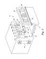
- FIG. 7is an exploded perspective view of one embodiment of the fluid processing cartridge that is supplied to the treatment location, comprising a tray in which a fluid processing circuit is contained;
- FIG. 8is an assembled perspective view of the fluid processing cartridge shown in FIG. 7;
- FIG. 9is a side section view of the fluid processing cartridge shown in FIGS. 7 and 8, showing the cartridge as it is supplied in a closed, sterile condition to the treatment location;
- FIG. 10is a perspective view of the cartridge shown in FIGS. 7 to 9 , in preparation of being mounted on the hemofiltration machine shown in FIG. 2;
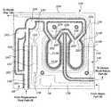
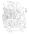
- FIG. 11is an embodiment of a fluid circuit that the cartridge shown in FIG. 10 can incorporate, being shown in association with the pumps, valves, and sensors of the hemofiltration machine shown in FIG. 2;
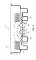
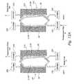
- FIGS. 12A and 12Bare largely schematic side section views of one embodiment of fluid balancing compartments that can form a part of the circuit shown in FIG. 11, showing their function of volumetrically balancing replacement fluid with waste fluid;
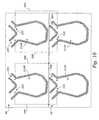
- FIGS. 13A, 13 B, and 13 Care perspective views of a bag configured with a pattern of seals and folded over to define a overlaying flexible fluid circuit that can be placed in a fluid processing cartridge of a type shown in FIG. 11;
- FIG. 14is a plane view of the pattern of seals that the bag shown in FIGS. 13A, 13 B, and 13 C carries, before the bag is folded over on itself;
- FIG. 15is a plane view of the overlaying fluid circuit that the bag shown in FIG. 14 forms after having been folded over on itself;
- FIG. 16is a largely schematic side section view of the overlaying fluid balancing compartments that are part of the circuit shown in FIG. 15, showing their function of volumetrically balancing replacement fluid with waste fluid;
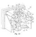
- FIG. 17is a front perspective view of an embodiment of a chassis panel that the hemofiltration machine shown in FIG. 2 can incorporate;
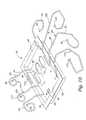
- FIG. 18is a back perspective view of the chassis panel shown in FIG. 17, showing the mechanical linkage of motors, pumps, and valve elements carried by the chassis panel;
- FIG. 19is a diagrammatic view of a telemetry network that can form a part of the system shown in FIG. 1;
- FIG. 20is a diagrammatic view of overlays for imparting control logic to the machine shown in FIG. 2;
- FIG. 21is an embodiment of a set for attaching multiple replacement fluid bags to the cartridge shown in FIG. 10, the set including an in-line sterilizing filter;
- FIG. 22is a plane view of a graphical user interface that the hemofiltration machine shown in FIG. 2 can incorporate.
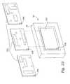
- FIG. 23is a perspective view of a generic user interface which can be customized by use of a family of interface templates, which the hemofiltration machine shown in FIG. 2 can incorporate.
- FIG. 1shows a system 10 that makes it possible for a person whose renal function is impaired or lacking, to receive convenient and therapeutically effective hemofiltration on a frequent basis, e.g., at least four times weekly and, preferably, six times weekly.
- the frequent hemofiltration therapy that the system 10 provideshas as one of its objectives the maintenance of uremic toxin levels in the person's blood within a comfortable range, e.g., at no more than 80% of the maximum level.
- the system 10can provide either acute or chronic treatment of renal impairment or failure.
- the system 10delivers the durable and disposable equipment and materials necessary to perform frequent hemofiltration on the person at a designated treatment location 12 .
- the location 12can vary. It can, for example, be a setting where support and assistance by one or more medically trained care givers are immediately available to the person, such as at a hospital, an outpatient clinic, or another treatment center. Alternatively, the location 12 can comprise a setting where support or assistance are provided by a trained partner, such as in the person's residence.
- the system 10can make it possible for the person to perform frequency hemofiltration in a non-clinical setting, without direct assistance from technically or medically trained persons.
- Each device 14may be generally constructed in the manner disclosed in pending U.S. patent application Ser. No. 08/724,948, filed Nov. 20, 1996, and entitled “Subcutaneously Implanted Cannula and Method for Arterial Access.”
- the devices 14preferably support high blood flow rates at or above 300 ml/min and preferably at least 600 ml/min.
- the devices 14also enable quick and frequent cannulation.
- the devices 14thereby reduce the time required to set up, perform, and complete a frequent hemofiltration session.
- the high blood flow rates that the devices 14 supportalso increase the removal rate of uremic toxins during hemofiltration, as will be described in greater detail later.
- the system 10supplies to the treatment location 12 a durable hemofiltration machine 16 .
- the system 10also supplies fluid processing cartridges 18 to the treatment location 12 , for installation on the machine 16 at the time of treatment.
- the system 10further supplies ancillary materials 20 , such as replacement fluids, to the treatment location 12 for use in association with the cartridge 18 and machine 16 .
- the system 10also preferably supplies a telemetry network 22 , to enable centralized, off-site monitoring and supervision of the frequent hemofiltration treatment regime.
- the system 10includes a source 24 that supplies a hemofiltration machine 16 (which can also be called a “cycler”) to the treatment location 12 .
- the machine 16is intended to be a durable item capable of long term, maintenance free use.
- FIG. 2shows a representative embodiment of a machine 16 capable of performing frequent hemofiltration.
- the machine 16is preferably lightweight and portable, presenting a compact footprint, suited for operation on a table top or other relatively small surface normally found, e.g., in a hospital room or in a home.
- the compact size of the machine 16also makes it well suited for shipment to a remote service-depot for maintenance and repair.
- the machine 16includes a chassis panel 26 and a panel door 28 that moves on a pair of rails 31 in a path toward and away from the chassis panel 26 (as shown by arrows in FIG. 2 ).
- a slot 27is formed between the chassis panel 26 and the door 28 .
- FIGS. 3 to 4show, when the door 28 is positioned away from the panel 26 , the operator can, in a simple vertical motion, move a fluid processing cartridge 18 into the slot 27 and, in a simple horizontal motion, fit the cartridge 18 onto a raised portion of the chassis panel 26 . When properly oriented, the fluid processing cartridge 18 rest on the rails 31 to help position the cartridge 18 .
- FIG. 5shows, movement of the door 28 toward the panel 26 engages and further supports the cartridge 18 for use on the panel 26 for use. This position of the door 28 will be called the closed position.
- the machine 16preferably includes a latching mechanism 30 and a sensor 32 (see FIG. 2) to secure the door 28 and cartridge against movement before enabling circulation of fluid through the cartridge 18 .
- the processing cartridge 18provides the blood and fluid interface for the machine 16 .
- the machine 16pumps blood from the person, through the fluid processing cartridge 18 to a hemofilter 34 (mounted in brackets to the side of the chassis panel 26 , as shown in phantom lines in FIGS. 2 to 5 ), back to the cartridge 18 , and then back to the person.
- a hemofilter 34mounted in brackets to the side of the chassis panel 26 , as shown in phantom lines in FIGS. 2 to 5 .
- the hemofilter 34can form an integrated part of the cartridge 18 .
- the hemofilter 34is connected via the cartridge 18 to the person's blood supply through the vascular access devices 14 .
- the machine 16includes a blood handling unit 36 mounted on the chassis panel 26 .
- the blood handling unit 36includes a peristaltic blood pump 92 and various clamping and sensing devices (described later).
- the blood handling unit 36circulates the person's blood in a controlled fashion through the hemofilter 34 and back to the person.
- the hemofilter 34removes waste fluid containing urea and other toxins.
- the machine 16also includes a fluid management unit 38 mounted on the chassis panel 26 .
- the fluid management unit 38includes a peristaltic waste and replacement fluid pump 152 and various clamping and sensing devices(described later).
- the fluid management unit 38replaces the waste fluid with a sterile replacement fluid, for return with the treated blood to the person's blood supply.
- the replacement fluidalso acts to maintain the person's electrolytic balance and acid/base balance.
- the fluid management unit 38includes a fluid balancing element 40 mounted on the chassis panel 26 .
- the fluid balancing element 40meters the return replacement fluid in proportion to the amount of waste fluid removed.
- the fluid balancing element 40includes one or more balancing chambers 206 , 208 and associated clamping devices(the details of which will be described later).
- the chambers 206 , 208comprise preformed depressions formed in the raised portion of the chassis panel 26 .
- preformed depressions on the door 28form mating chambers 206 ′, 208 ′, which register with the chassis panel chambers 206 , 208 .
- the registered chambers 206 / 206 ′and 208 / 208 ′define between them spaces of known volume, e.g., 20 ml.
- the known volumecan, of course, be greater or less than 20 ml, and the chambers 206 / 206 ′ and 208 / 208 ′ can each have a different known volume.
- flexible containers 212 and 214which form a part of a preformed fluid circuit carried within the fluid processing cartridge 18 , fit into the registered chambers 206 / 206 ′ and 208 / 208 ′.
- the chambers 206 / 206 ′ and 208 / 208 ′ and associated clamping devicesinteract with the containers 212 and 214 , to provide the capability of balancing waste and replacement fluid volumetrically, in an accurate, straightforward manner, without use of weigh scales and weight sensing.
- the machine 16also includes an ultrafiltration unit 42 on the chassis panel 26 .
- the ultrafiltration unit 42includes a peristaltic ultrafiltration pump 144 to remove additional waste from the person without addition of replacement fluid.
- the machine 16provides, at the end of each frequent hemofiltration session, a net ultrafiltration fluid loss, which coincides with an amount prescribed by the attending physician.
- the machine 16completes a frequent hemofiltration session when a prescribed replacement fluid volume has been exchanged and the net ultrafiltration fluid loss target has been met.
- the machine 16can accommodate continuous or extended treatment sessions on an automated basis.
- the machine 16can also accommodate operation based upon individually set ultrafiltration rates, blood flow rates, or return fluid flow rates, with completion determined by the volume of replacement fluid exchanged or by a treatment timer.
- the various pumping, clamping, and sensing devices on the machine 16provide blood flow, fluid management, and safety functions by sensing pump pressures, detecting air, detecting blood leak through the hemofilter 34 , and sensing waste pressure.
- the sensorsalso provide addition fluid management and safety functions, such as sensing replacement fluid temperature and replacement fluid pump pressure.
- the machine 16also provides other processing functions, such as priming, supplying a replacement fluid bolus, and carrying out a rinseback of the person's blood.
- the machine 16also preferable includes an operator interface 44 , which, in the illustrated embodiment (see FIG. 2) is carried on the exterior of the door 28 .
- the interface 44provides simple switch and/or knob operation of the machine 16 , preferably by use of one hand.
- the interface 44displays information necessary to operate the machine 16 , presenting an uncluttered display and tactile touch buttons to intuitively lead a person without technical or medical background through set up and operation of the machine 16 with a minimum of training.
- the source 24 supplying the machine 16can comprise a company or business that manufactures the machine 16 or otherwise distributes the machine 16 to the treatment location 12 on a sale, lease, or rental basis.
- the system 10further includes a source 46 for supplying a fluid processing cartridge 18 to the treatment location 12 for use in association with the machine 16 .
- the cartridge 18is intended to be disposable item, capable of single or extended use, which the loads on the machine 16 before beginning a hemofiltration session (as FIGS. 3 to 5 show).
- the cartridge 18can be removed from the machine 16 and discarded upon the completing the hemofiltration session, or its use can be extended to one or more subsequent sessions, as will be described later.
- the cartridge 18couples to the person's vascular access devices 14 and interacts with the machine 16 to draw, process, and return blood in a continuous, extracoporeal path, to carry out fluid balancing through waste removal, replacement fluid exchange, and ultrafiltration.
- the tasks of loading and unloading the cartridge 18are simple and straightforward, following a simple, straight loading and unloading path into the slot 27 and against the chassis panel 26 , as FIGS. 3 to 5 show.
- the person receiving hemofiltrationcan by himself/herself set up the cartridge 18 and machine 16 , without necessarily requiring assistance from a technically or medically trained person.
- the cartridge 18preferably provides the entire blood and fluid interface for the machine 16 , including all pumping, valving, pressure sensing, air detection, blood leak detection, and tubing management.
- the cartridge 18preferable is supplied to the treatment location 12 with all tubing, access needles and waste and replacement fluid connections preconnected.
- a waste bagalso can be preattached, if desired, or the waste line can be placed in a drain.
- Loading the cartridge 18 on the chassis panel 26 and closing the door 28also automatically locates all sensors of the machine's safety function in association with the blood fluid interface. The operator is not required to load anything else to carry out the machine's safety function. Once the machine 18 undergoes start up testing to confirm cartridge placement and integrity and to confirm the functionality of the sensors, subsequent automated operation the machine 18 in a safe mode is assured.
- the cartridge 18can be constructed in various ways.
- the cartridge 18includes a preformed tray 48 and insert 53 manufactured, e.g., by thermoforming polystyrene or another comparable material.
- the tray 48 and insert 53are peripherally joined together, e.g., by ultrasonic welding.
- the trayincludes a base 50 , side walls 52 , and an open top edge 54 .
- the geometry of the tray 48is appropriately keyed to fit in only one orientation on the rails 31 in the slot 27 between the chassis panel 26 and door 28 of the machine 16 .
- the insert 53rests on the raised portion of the chassis panel 26 . Closing the door 28 secures the tray 48 to the panel 26 .
- a preformed circuit 56is carried between the base 50 of the tray 48 and the insert 53 .
- the circuit 56is arranged to carry blood, waste, and replacement fluid during hemofiltration.
- the circuit 56includes an array of fluid flow paths formed with in-line flexible containers 212 and 214 (for fluid balancing), peristaltic pump headers, sensor stations, tubing, and valve stations.
- the layout of flow paths, containers, pump headers, sensing stations, and valve stations on the circuit 56form a mirror image of the layout of the structural and mechanical components on the chassis panel 26 and door 28 of the machine 16 .
- the insert 53includes cut outs 58 to expose the containers, peristaltic pump headers, sensing stations, and valve stations for engagement with equipment on the chassis panel 26 .
- the in-line containers 212 / 214 formed in the circuit 56fit within the registered chambers 206 / 206 ′ and 208 / 208 ′ on the chassis panel 26 and door 28 .
- the pump headers and the sensor and valve stations on the circuit 56overlay and engage corresponding peristaltic pumps, sensors, and valve on the chassis panel 26 .
- the base 50 of the tray 48 underlaying the pump stationsis relieved, to form pump races 360 .
- the inside surface of the door 28carries concave pump races 362 supported by springs 364 (see FIGS. 6 A and 6 B).
- the spring loaded pump races 362 on the door 28nest with the relieved pump races 360 on the tray 48 , to provide rigidity and support.
- the pump races 360can form cutouts in the base 50 (like cut outs 58 in the insert, as earlier described), through which the pump races 362 on the door 28 extend.
- the base 50 of the tray 48 underlying the containers 212 / 214is also relieved, to form chamber supports 368 .
- the tray supports 368fit within the door chambers 206 ′ and 208 ′. The door 28 therefore engages the tray 48 , to add overall rigidity and support to the tray base 50 .
- the containers 212 / 214are enclosed within the registered chambers 206 / 206 ′ and 208 / 208 ′ and tray chamber supports 368 , which define for the containers 212 / 214 to a known maximum volume.
- the peristaltic pumps, sensors, and valve stations on the machine 16interact with the flexible components of the circuit 56 .
- the cartridge 18makes possible direct, centralized connection of a blood-fluid interface to the blood pump, the waste and replacement pump, the ultrafiltration pump, the fluid balancing chambers, the sensor devices, and the clamping devices of the machine 16 , with no air interfaces.
- the compact arrangement of the cartridge 18also reduces fluid pressure drops, thereby accommodating high flow rates, e.g., an arterial blood line pressure drop of less than 250 mmHg at a flow rate of 600 ml/min and a hematocrit of 25.
- FIGS. 9 and 10show, lengths of flexible tubing FT are coupled to the circuit 56 in the base 50 of the tray 48 and rest in coils on top of the insert 53 within the tray 48 during shipment and before use (see FIG. 9 ).
- a removable lid 60made, e.g., from ethylene oxide permeable TYVEKTM material or polyethylene plastic sheet stock, covers and seals the interior of the tray 48 prior to use.
- the cartridge 18can therefore be sterilized by exposure to ethylene oxide prior to use. Other methods of sterilization, e.g., gamma radiation or steam sterilization, can be used.
- the ultrasonically welded assembly of the tray 58 , insert 53 , and the circuit 56 (with attached tubing FT)can be packaged as a unit into a sealed plastic bag for sterilization, obviating the need for the lid 60 .
- the lid 60is peeled away, or, in the alternative arrangement, the sealed plastic bag is opened.
- the attached flexible tubing FTis extended beyond the bounds of the tray 48 to make connection with external processing items (see FIG. 10 ).
- the tubing FTcarries appropriate couplers for this purpose.
- the tray 48is moved along a vertical path for loading into the slot 27 and then a horizontal path for loading on the raised portion of the chassis panel 26 , after which a simple motion of the door latching mechanism 30 aligns the entire fluid circuit, 56 with the pumps, sensors, and clamps on the chassis panel 26 . There is no area of blood or fluid contact that this outside the disposable circuit 56 .
- the source 46 supplying the cartridge 18can comprise a company or business that manufactures the cartridge 18 or that otherwise distributes the cartridge 18 to the treatment location 12 on a sale, lease, or rental basis.
- FIG. 11shows a representative fluid circuit 56 that is well suited for carrying out frequent hemofiltration, and which can be incorporated into the cartridge 18 for interface with pumps, valves, and sensors arranged as a mirror image on the chassis panel 26 .
- the fluid circuit 56couples the hemofilter 34 to several main fluid flow paths.
- the main fluid flow pathscomprise an arterial blood supply path 62 , a venous blood return path 64 , a blood waste path 66 , a replacement fluid path 68 , and an ultrafiltration/fluid balancing path 70 .
- the arterial blood supply path 62 and venous blood return path 64includes lengths of flexible tubing 72 and 74 that extend outside the tray 48 (see FIG. 10 ). As FIG. 10 shows, The paths 72 and 74 carry cannulas 76 at their distal ends (or connectors that enable connection to cannulas 76 ), to enable connection, respectively, to the person's arterial and venous access devices 14 .
- the arterial blood supply path 62also includes a length of flexible tubing 78 (see FIG. 10) that extends outside the tray 48 .
- the tubing 78includes a distal connector 80 to couple to the blood inlet 82 of the hemofilter 34 .
- the venous blood return path 64includes a length of flexible tubing 84 that extends outside the tray 48 .
- the tubing 84includes a distal connector 86 to couple to the blood outlet 88 of the hemofilter 34 .
- the hemofilter 34can be an integral part of the tray 48 .
- the arterial and venous blood paths 78 and 84are supplied pre-connected to the hemofilter 34 .
- the exterior tubing components of the arterial or venous blood pathscan include injection sites 90 .
- the sitescan be used, e.g., to remove trapped air or to inject anticoagulant, medication, or buffers into the blood flows.
- the exterior tubing components of the arterial or venous blood pathscan also include conventional pinch clamps, to facilitate patient connection and disconnection.
- the remaining portions of arterial and venous blood paths 62 and 64are contained in the circuit 56 held within the tray 48 .
- the blood pump 92 of the machine 16engages a pump header region 94 in the arterial blood supply path 62 within the tray 48 upstream of the hemofilter 34 , to convey blood into and through the hemofilter 34 .
- An arterial blood clamp 96 and a patient connection-disconnection (air bubble detector) sensor 98 on the machine 16engage a clamp region 100 and a sensor region 102 in the arterial blood supply path 62 within the tray 48 upstream of the blood pump 92 .
- an air bubble sensor(not shown) can be located downstream of the blood pump 92 and upstream of the hemofilter 34 .
- the placement of the air sensor 98 upstream of the hemofilter 34allows air bubbles to be detected prior to entering the hemofilter 34 .
- air bubblesbreak up into tiny micro-bubbles, which are not as easily detected.
- Placement of the air sensor 98 upstream of the hemofilter 34also serves the additional purpose of detecting air when the blood pump 92 is operated in reverse, to rinse back blood to the patient, as will be described later.
- An air detector 108 on the machine 16engages a sensing region 110 in the venous blood return path 64 within the tray 48 downstream of the hemofilter 34 .
- a venous clamp 112 on the machine 16engages a clamp region 114 in the venous blood return path 64 within the tray 48 downstream of the air detector 108 .
- the membrane (not shown) located in the hemofilter 34separates waste including liquid and uremic toxins from the blood.
- a waste outlet 116conveys waste from the hemofilter 34 .
- the blood waste path 66includes a length of flexible tubing 118 (see FIG. 10) that extends beyond the tray 48 .
- the tubing 118carries a distal connector 120 to couple to the waste outlet 116 of the hemofilter 34 .
- the waste path 66can be supplied pre-connected to the hemofilter 34 .
- the waste path 66also includes a length of flexible tubing 122 that extends beyond the tray 48 .
- the tubing 122carries a connector 124 to couple to a waste bag 126 or an external drain. Alternatively, the waste bag 126 can be preconnected to the tubing 122 .
- the remainder of the waste path 66is contained within the circuit 56 inside the tray 48 .
- a blood leak detector 128 on the machine 16engages a sensor region 130 in the waste path 66 downstream of the hemofilter 34 .
- a waste pressure sensor 132 on the machine 16engages another sensor region 134 in the waste path 66 downstream of the blood leak detector 128 .
- the waste path 66branches into an ultrafiltration path 136 and a balancing path 138 .
- the ultrafiltration branch path 136bypasses in-line containers 212 and 214 of the circuit 56 .
- the ultrafiltration pump 144 on the machine 16engages a pump header region 146 in the ultrafiltration branch path 136 within the tray 48 .
- the waste balancing branch path 138communicates with the in-line containers 212 and 214 .
- the waste and replacement fluid pump 152 on the machine 16engages a pump header region 154 in the waste balancing branch path 138 within the tray 48 upstream of the in-line containers 212 and 214 .
- a pressure sensor 156 on the machine 16engages a sensor region 160 in the waste balancing branch path 138 within the tray 48 between the waste and replacement fluid pump 152 and the in-line containers 212 and 214 .
- the pressure sensor 156senses the fluid pressure required to convey replacement fluid into the venous return line. This resistance to the flow of replacement fluid is the venous blood pressure.
- the pressure sensor 156 in the waste fluid path 138thereby serves to sense the venous blood pressure.
- a flush clamp 162engages a clamp region 164 in the waste path 66 within the tray 48 downstream of the in-line containers 212 and 214 .
- a waste clamp 166engages a clamp region 168 in the waste path 66 downstream of the flush clamp 162 .
- the circuit 56 in the tray 48also can include an air break 170 , which communicates with the waste path 66 downstream of the waste clamp 166 . The air break 170 prevents back flow of contaminants into the circuit 56 from the waste bag 126 or drain.
- the replacement fluid path 68includes a length of flexible tubing 172 that extends outside the tray 48 .
- the tubing 172includes a distal connector 174 or connectors that enable connection to multiple containers of replacement fluid 176 .
- the tubing 172can also include an in-line 0.2 m sterilizing filter 178 to avoid contamination of the circuit 56 .
- the containers 176 togethertypically hold from 8 to 20 combined liters of replacement fluid, depending upon the fluid removal objectives of the particular frequent hemofiltration procedure.
- the replacement fluidis also used to prime the fluid circuit 56 at the outset of a treatment session and to rinse back blood to the patient at the end of a treatment session.
- the remainder of the replacement fluid path 68is contained in the circuit 56 within the tray 48 .
- Sensing region 186 in the replacement fluid path 68 inside the tray 48engages a replacement fluid flow rate detector 182 on the machine 16 .
- a clamping region 190 in the replacement fluid path 68 inside the tray 48engages a replacement fluid clamp 188 on the machine 16 .
- the replacement fluid path 68includes a priming or bolus branch path 192 that communicates with the arterial blood supply path 62 .
- a clamping region 196 in the priming branch path 192engages a priming clamp 194 on the machine 16 .
- the replacement fluid path 68also includes a balancing branch path 198 that communicates with the venous blood return path 64 , via the in-line containers 212 and 214 .
- a pump header region 200 in the balancing replacement branch path 198engages the waste and fluid replacement pump 152 on the machine 16 upstream of the in-line containers 212 and 214 .
- the waste and fluid replacement pump 152comprises a dual header pump, simultaneously engaging the two pump header regions 154 and 200 on the waste path 66 and the replacement fluid path 68 .
- a sensor region 204 in the balancing replacement branch path 198engages a pressure sensor 202 on the machine 16 between the waste and replacement fluid pump 152 and the in-line containers 212 and 214 .
- the pressure sensor 202senses the pressure required to convey waste fluid into the waste return line. This resistance to the flow of waste fluid is the waste line pressure.
- the pressure sensor 202 in the replacement fluid path 198thereby serves to sense the waste line pressure.
- the pressure sensor 156 in the waste fluid path 138serves to sense the venous blood pressure.
- the ultrafiltration waste branch path 136 within the tray 48which bypasses the in-line containers 212 and 214 of the circuit 56 , accommodates transfer of a prescribed volume of waste to the waste bag 126 , without an offsetting volume of replacement fluid.
- the circuit 56thereby is capable of performing an ultrafiltration function.
- the balancing waste branch path 138 and the balancing replacement branch path 198pass through the in-line containers 212 and 214 in the circuit 56 contained within the tray 48 .
- the in-line containers 212 and 214transfer a volume of replacement fluid to the venous blood return path 64 in proportion to the volume of waste fluid removed, except for the volume making up the ultrafiltration volume loss.
- the circuit 56is thereby capable of performing a fluid balancing function in addition to the ultrafiltration function.
- the machine 16 and circuit 56carry out the fluid balancing function volumetrically, without weight sensing. More particularly, the registered chambers 206 / 206 ′ and 208 / 208 ′ on the chassis panel 26 and door 28 of the machine 16 receive the in-line containers 212 and 214 when the tray 48 is mounted on the chassis panel 26 .
- the registered chambers 206 / 206 ′ and 208 / 208 ′mutually impose volumetric constraints on the in-line containers 212 and 214 , to define a maximum interior volume for each of the on-line containers 212 and 214 .
- FIGS. 12A and 12Bshow one embodiment of the right and left orientation of the containers 212 and 214 , with the containers 212 and 214 also shown in side section.
- each in-line container 212 and 214is itself divided along their midline from front to back by an interior flexible wall 210 , to form four compartments.
- two of the compartmentsface the door 28 , and are thus designated as front compartments 212 F and 214 F.
- the other two compartmentsface the chassis panel 26 , and will thus be designed as rear compartments 212 R and 214 R.
- Each in-line container 212 and 214has a waste side compartment communicating with waste path 66 and a replacement side compartment communicating with the replacement fluid path 68 .
- the circuit 56establishes communication between the balancing waste branch path 138 and the rear compartments 212 R and 214 R (which will also be called the waste side compartments).
- the circuit 56also establishes communication between the balancing replacement branch path 198 and the front compartments 212 R and 214 R (which will also be called the replacement side compartments).
- fluidenters the compartments from the bottom and exits the compartments from the top. Other flow paths into and from the compartments can be established, as will be described later.
- the machine 16includes an inlet valve assembly 216 and an outlet valve assembly 218 on the chassis panel 26 , located in association with the chambers 206 and 208 .
- the circuit 56 in the tray 48likewise includes, for each in-line container 212 and 214 , an inlet clamp region 220 and an outlet clamp region 222 , which govern flow into and out of the waste side compartments 212 R and 214 R.
- the circuit 56 in the tray 48also includes, for each in-line container 212 and 214 , an inlet clamp region 224 and an outlet clamp region 226 , which govern flow into and out of the replacement side compartments 212 F and 214 F.
- the inlet and outlet valve assemblies 216 and 218 on the machine 16engage the corresponding waste and replacement fluid inlet and outlet clamp regions 220 , 222 , 224 , 226 in the circuit 56 .
- the machine 16toggles the operation of inlet and outlet valve assemblies 216 and 218 to synchronize the flow of fluids into and out of the waste side and replacement side compartments of each in-line container 212 and 214 .
- the waste side inlet valve 220is opened while the waste side outlet valve 222 is closed. Waste fluid is conveyed by operation of the waste and replacement pump 152 from the waste path 66 into the waste side compartment of the given in-line container 212 and 214 . Simultaneously, for the same in-line compartment 212 and 214 , the replacement side inlet valve 224 is closed and the replacement side outlet valve 226 is opened, so that the incoming flow of waste in the waste side compartment displaces the interior wall 210 to express a like volume of replacement fluid from the replacement side compartment into the venous blood return path 64 .
- an opposite valve actionoccurs (see FIG. 12 B).
- the replacement side inlet valve 224is opened and the replacement side outlet valve 226 is closed, and replacement fluid is conveyed into the replacement side compartment from the replacement fluid path 68 .
- the incoming replacement fluiddisplaces the interior wall 210 to express a like volume of waste fluid from the waste side compartment to the waste bag 126 (the waste side inlet valve 220 now being closed and the waste side outlet valve 222 now being opened).
- valve assemblieswork in tandem upon the two in-line containers 212 and 214 , with one container 140 receiving waste and dispensing replacement fluid, while the other container 142 receives replacement fluid and dispenses waste, and vice versa.
- the circuit 56provides a continuous, volumetrically balanced flow of waste fluid to the waste bag 126 and replacement fluid to the venous blood return path 64 .
- FIGS. 13A to 13 Cshow a fluid circuit bag 228 made from two overlaying sheets 230 A and 230 B of flexible medical grade plastic, e.g., poly vinyl chloride (see FIG. 13 A).
- the bag 228When laid flat (see FIG. 13 B), the bag 228 defines first and second panels 232 and 234 divided along a midline 236 .
- the first and second panels 232 and 234are brought into registration in a reverse facing relationship, with one panel 232 comprising the front of the bag 228 and the other panel 234 comprising the back of the bag 228 .
- the first and second panel 232 and 234each includes an individual pattern of seals S formed, e.g., by radio frequency welding.
- the seals Sform fluid flow paths, including the in-line containers 212 and 214 , peristaltic pump header regions, the sensor regions, and clamp regions previously described.
- the flow paths formed by the pattern of seals Scan comprise all or part of the circuit 56 .
- Pump header tubing lengths 155 , 145 , and 201are sealed in placed within the seal pattern S to form the pump regions 154 , 146 , and 201 , respectively.
- the seals S on the first panel 232are configured to form the flow paths of the circuit 56 through which replacement fluid is conveyed from the replacement fluid path 68 to the venous blood return path 64 , including the left and right front-facing replacement fluid compartments 212 F and 214 F.
- the seals S on the second panel 234are configured to form the flow paths of the circuit 56 through which waste fluid is conveyed from the waste path 66 to the waste bag 126 or drain, including the left and right rear-facing waste fluid compartments 212 R and 214 R. Seals S form four individual containers, two containers 212 F and 214 F on the panel 232 , and two containers 212 R and 214 R on the panel 234 .
- the bag 228is folded over about its midline 236 (see FIG. 15 ).
- the bag 228places in close association or registry the waste and replacement fluid paths 66 and 68 of the circuit 56 .
- the replacement fluid paths 68 of the circuit 56occupy the front panel 232 of the bag 228
- the waste paths 66 of the circuit 56occupy the back panel 234 of the bag 228 (or vice versa, depending upon the desired orientation of the bag 228 ).
- the folded over bag 228is contained in the base 50 of the tray 48 , with portions exposed through cutouts 58 in the insert 51 for engagement with the machine peristaltic pumps, sensing elements, and clamping elements, in the manner shown in FIG. 10 .
- the remaining portions of the circuit 56 not contained within the bag 228are formed of tubing and fit into preformed areas in the base 50 of the tray 48 (or formed within another bag) and coupled in fluid communication with the flow paths of the bag 228 , to complete the circuit 56 shown in FIG. 10 .
- the flow paths formed on the first panel 232include the balance replacement fluid paths 198 , which lead to and from the replacement side compartments 212 F and 214 F.
- the replacement side compartments 212 F and 214 Frest in recesses in the tray base 50 .
- Cutouts 58 in the insert 51expose the pump header regions 200 and 154 , to engage the peristaltic waste and replacement pump 152 on the machine 16 ; the inlet clamp regions 224 , to engage the inlet valve assembly 216 on the machine 16 to control inflow of replacement fluid into the replacement side compartments 212 F and 214 F; and the outlet clamp regions 226 , to engage the outlet valve assembly 218 on the machine 16 to control outflow of replacement fluid from the replacement side compartments 212 F and 214 F.
- the cutouts 58also expose the sensor region 204 , to engage the pressure sensor 202 downstream of the waste and replacement pump 152 , and a pressure relief path 240 with exposed pressure relief bypass valve 242 , the purpose of which will be described later.
- a small opening 203 formed in the pump header tubing 201opens communication with the relief path 240 .
- the flow paths formed on the second panel 234include the waste path 138 that lead to and from the waste side compartments 212 R and 214 R (for fluid balancing) and the waste path 136 that bypasses the waste side compartments 212 R and 214 R (for ultrafiltration).
- FIG. 15shows, when the bag 228 is folded over in the tray 48 , the waste compartments 212 R and 214 R on the waste panel 234 and the replacement compartments 212 F and 214 F on the replacement panel 232 overlay, so both are exposed through the cutout 58 in the insert for registry as a unit with the chambers 206 and 208 on the chassis panel 26 .
- the flow paths on the waste panel 234also include the exposed waste inlet clamp regions 220 , to engage the valve assembly 218 to control inflow of waste fluid into the waste compartments 212 R and 214 R, and the exposed waste outlet clamp regions 222 , to engage the valve assembly 216 to control outflow of waste fluid from the waste compartments 212 R and 214 R.
- the inlet clamp regions of the waste compartments 212 R and 214 R formed on the waste panel 234overlay the outlet clamp regions of the replacement compartments 212 F and 214 F formed on the replacement panel 232 , and vice versa.
- the flow pathsalso includes an exposed pump header region 154 , to engage the peristaltic waste and replacement pump 152 .
- the exposed pump header regions 200 and 154 on the replacement and waste panels 232 and 234lay side-by-side, to accommodate common engagement with the dual header waste and replacement pump 152 .
- the flow pathsalso include the sensor region 160 , to engage the pressure sensor 156 downstream of the waste and replacement fluid pump 152 .
- the flow pathsalso include the pump header region 146 , to engage the peristaltic ultrafiltration pump 144 .
- the exposed pump header region 146 for the ultrafiltration pump 144is spaced away from the other pump header regions of the circuit 56 .
- the entry paths serving the waste and replacement compartmentsare located at the bottom, while the exit paths serving the waste and replacement compartments are located at the top. This configuration facilitates priming of the compartments. Still, the spaced apart configuration requires eight valve assemblies.
- the entry and exit paths serving the waste and replacement compartmentsare all located at the top. Priming is still achieved, as the paths are top-oriented. Furthermore, due to the folded-over configuration of the bag itself, the clamping regions 220 , 222 , 226 can be arranged overlay one another. The overlaying arrangement of the clamping regions 220 , 222 , 224 , and 226 serving the waste and replacement compartments simplifies the number and operation of the inlet and outlet valve assemblies 216 and 218 on the machine 16 .
- the first clamping element 244is movable into simultaneous clamping engagement with the inlet clamp region 224 of the left replacement compartment 212 F (on the replacement panel 232 ) and the outlet clamp region 222 of the left waste compartment 212 R (on the waste panel 234 ), closing both.
- the fourth clamping element 250is movable into simultaneous clamping engagement with the inlet clamp region 224 of the right replacement compartment 214 F (on the replacement panel 232 ) and the outlet clamp region 222 of the right waste compartment 214 R (on the waste panel 234 ), closing both.
- the second clamping element 246is movable into simultaneous clamping engagement with the outlet clamp region 226 of the left replacement compartment 212 F (on the replacement panel 232 ) and the inlet clamp region 220 of the left waste compartment 212 R (on the waste panel 232 ), closing both.
- the third clamping element 248is movable into simultaneous clamping engagement with the outlet clamp region 226 of the right replacement compartment 214 F (on the replacement panel 232 ) and the inlet clamp region 220 of the right waste compartment 214 R (on the waste panel 234 ), closing both.
- the machine 16toggles operation of the first and third clamping elements 244 , 248 in tandem, while toggling operation the second and fourth clamping elements 246 , 250 in tandem.
- first and third clamping elements 244 , 248are operated to close their respective clamp regions, replacement fluid enters the right replacement compartment 214 F to displace waste fluid from the underlying right waste compartment 214 R, while waste fluid enters the left waste compartment 212 R to displace replacement fluid from the overlaying left replacement compartment 212 F.
- FIGS. 17 and 18show a mechanically linked pump and valve system 300 that can be arranged on the chassis panel 26 and used in association with the layered fluid circuit bag 228 shown in FIG. 15 .
- the system 300includes three electric motors 302 , 304 , and 306 .
- the first motor 302is mechanically linked by a drive belt 308 to the dual header waste and replacement pump 152 , previously described.
- the second motor 304is mechanically linked by a drive belt 310 to the blood pump 92 , also previously described.
- the third motor 306is mechanically linked by a drive belt 312 to the ultrafiltration pump 144 , also as previously described.
- a drive belt 314also mechanically links the first motor to the first, second, third, and fourth clamping elements 244 , 246 , 248 , and 250 , via a cam actuator mechanism 316 forming a synchronization unit or mechanism.
- the cam actuator mechanism 316includes, for each clamping element 244 , 246 , 248 , and 250 a pinch valve 318 mechanically coupled to a cam 320 .
- the cams 320rotate about a drive shaft 322 , which is coupled to the drive belt 314 .
- Rotation of the cams 320advances or withdraws the pinch valves 318 , according to the surface contour machined on the periphery of the cam 320 .
- the pinch valve 318closes the overlying clamp regions of the fluid circuit bag 228 that lay in its path.
- the pinch valve 318opens the overlying clamp regions.
- the cams 320are arranged along the drive shaft 322 to achieve a predetermined sequence of pinch valve operation. During the sequence, the rotating cams 320 first simultaneously close all the clamping elements 244 , 246 , 248 , and 250 for a predetermined short time period, and then open clamping elements 244 and 248 , while closing clamping elements 246 and 250 for a predetermined time period. The rotating cams 320 then return all the clamping elements 244 , 246 , 248 , and 250 to a simultaneously closed condition for a short predetermined time period, and then open clamping elements 246 and 250 , while closing clamping elements 244 and 248 for a predetermined time period.
- a chamber cycleoccurs in the time interval that the valve elements 244 , 246 , 248 , and 250 change from a simultaneously closed condition and return to the simultaneously closed condition.
- the cam actuator mechanism 316mechanically links the clamping elements 244 , 246 , 248 , and 250 ratiometrically with the first motor 302 . As the motor 302 increases or decreases the speed of the dual header waste and replacement pump 152 , the operation of the clamping elements 244 , 246 , 248 and 250 increases or decreases a proportional amount.
- the ratiois set so that the flow rate per unit time through the waste pump header region 154 (i.e., through waste path 66 ) approximately equals three-fourths of the volume of the waste compartment 212 R / 214 R, while maintaining the cycle rate at less than 10 cycles per minute. For example, if the chamber volume is 20 cc, the cycle occurs after 15 to 17 cc of waste fluid enters the compartment.
- the waste pump header region 154is made smaller in diameter than the replacement fluid header region 200 .
- the flow rate through the replacement fluid header region 200(through replacement fluid path 68 ) will always be larger than the flow rate through the waste pump header region 154 (through waste path 68 ).
- a pressure relief path 240 with pressure relief bypass valve 242is provided, to prevent overfilling.
- the valve 242is a mechanically spring biased pressure regulator, and serves the pressure regulation and bypass function of the machine 16 .
- the in-line compartment that receives waste fluidwill fill to approximately three-fourths of its volume during each cycle, displacing an equal amount of replacement fluid from its companion compartment.
- the other in-line compartment that receives replacement fluidwill fill completely. If the compartment completely fills with replacement fluid before the end of the cycle, the pressure relief bypass valve 242 will open to circulate replacement fluid through the relief path 240 to prevent overfilling. During the next cycle, waste fluid in the compartment will be completely displaced by the complete fill of replacement fluid in its companion compartment.
- the pump and valve system 300 used in association with the layered fluid circuit bag 228achieves accurate fluid balancing during frequent hemofiltration. Due to the smaller volumes of replacement fluid required during each frequent hemofiltration session, slight variations that may occur (e.g., plus or minus 5%) between fluid volume removed and fluid volume replaced do not lead to large volume shifts. As a result of accurate balancing of small fluid volumes, a person undergoing frequent hemofiltration does not experience significant day-to-day swings in body fluid volume, and more precise control of the person's body fluid and weight can be achieved.
- the chambers 206 / 206 ′ and 208 / 208 ′support containers 212 and 214 forming volumetric chambers that are acted upon by what may be referred to as flow assemblies, flow control assemblies, or portions thereof, that variously include clamping elements 244 , 246 , 248 , 250 and peristaltic waste and replacement fluid pump 152 , to balance waste and replacement fluid volumetrically.
- the system 10further includes a source 252 or sources that supply ancillary materials 20 to the treatment location 12 for use in association with the cartridge 18 and machine 16 .
- the ancillary materials 20include the replacement fluid containers 176 , as prescribed by the person's physician.
- the ancillary materials 20may also include an anticoagulant prescribed by a physician.
- anticoagulantmay not be required for every person undergoing frequent hemofiltration, depending upon treatment time, treatment frequency, blood hematocrit, and other physiologic conditions of the person.
- the ancillary materials 20can also include the hemofilter 34 , although, alternatively, the tray 48 can carry the hemofilter 34 , or the hemofilter 34 can comprise an integrated component of the cartridge 18 .
- the person's bloodis conveyed through the hemofilter 34 for removal of waste fluid containing urea and other toxins.
- Replacement fluidis exchanged for the removed waste fluid, to maintain the person's electrolyte balance and acid/base balance.
- the replacement fluidis also balanced against an additional waste fluid removal, to yield a net ultrafiltration loss, as prescribed by the person's physician.
- composition of an optimal replacement fluid solution usable during frequent hemofiltrationconsist of a balanced salt solution containing the major cationic and anionic plasma constituents, including bicarbonate or another anion from which net bicarbonate can be generated by metabolism.
- Specific cationic substances removed by frequent hemofiltration that require replacementtypically include sodium, potassium and calcium.
- Specific anionic substances removed by frequent hemofiltration that require replacementinclude chloride and either bicarbonate or another anion that can be metabolized into bicarbonate, such as acetate, citrate, or, typically, lactate.
- the replacement fluid for frequent hemofiltrationshould exclude phosphorus and other anionic substances. These materials typically accumulate in undesirable amounts in persons experiencing renal failure and are either difficult to remove in large amounts during hemofiltration or are safely removed without need for specific replacement.
- the concentration of sodium in a replacement fluid for frequent hemofiltrationshould fall slightly below that of the typical blood filtrate concentration of 135 to 152 meq/liter.
- the optimal range for sodium in the replacement fluid for frequent hemofiltrationis 128-132 meq/liter, and typically 130 meq/liter. This concentration allows for a net sodium removal during frequent hemofiltration sessions, which is easily tolerated due to the smaller replacement fluid volumes necessary for frequent hemofiltration. This concentration also results in a minimal net drop in serum osmolality, so as to decrease extracellular volume to a extent sufficient to maintain euvolemia while ameliorating thirst in the person undergoing frequent hemofiltration.
- the optimal concentration in a replacement fluid for frequent hemofiltrationshould be much closer to the normal physiologic range of calcium in plasma, i.e., in a range of 2.5 to 3.5 meq/liter, and typically 2.7 meq/liter.
- This calcium concentration rangeis required to prevent tetany, which can result from excessive removal of ionized calcium, while removing excessive serum calcium that may result from the oral calcium supplements and phosphorus binders frequently used by persons requiring hemofiltration.
- the potassium concentrations selected for replacement fluids used during infrequent hemofiltrationare quite low, e.g., in the range of 0 to 3 meq/liter. These low concentrations of potassium are required for infrequent hemofiltration therapies, to prevent life threatening accumulations of serum potassium between treatment sessions. Interim accumulation of toxic levels of potassium can be encountered between infrequent hemofiltration sessions, both because of decreased renal excretion of potassium and the interim development of acidosis between sessions. This, in turn, can result in total body potassium depletion in many persons undergoing infrequent therapy. Potassium depletion results in vasoconstriction and subsequent alterations in regional blood flow.
- Potassium depletionalso interferes with the efficiency of solute removal, as measured by a decrease in Kt/V for urea, which is a dimensionless parameter commonly employed to measure the adequacy of dialysis. Potassium depletion is also implicated in the pathogenesis of hypertension in patients undergoing hemodialysis or infrequent hemofiltration.
- the optimal range for potassium in a replacement fluid used for frequent hemofiltrationcan fall in a higher range than that required of less frequent treatment schedules, laying in the range of 2.7 to 4.5 meq/liter, and typically 4.0 meq/liter.
- This higher concentration of potassiumwhen infused frequently in smaller fluid replacement volumes, prevents potassium depletion, while also maintaining more stable potassium levels to prevent toxic accumulation of potassium between sessions.
- the optimal range for chloride concentrations in a replacement fluid used for frequent hemofiltrationis 105 to 115 meq/liter, and typically 109 meq/liter. This concentration most closely approximates the normal sodium to chloride ratio of 1.38:1 maintained in the plasma. The small deviation from this ratio in the replacement fluid itself allows for the normalization of the ratio by daily oral intake of these electrolytes. Due to the larger replacement fluid volumes needed for infrequent treatment (three times per week or less), this deviation from the normal 1.38:1 ratio are exaggerated, and can lead to a hyperchloremic acidosis. Due to the use of smaller fluid volumes during each frequent hemofiltration session, hyperchloremic acidosis can be avoided.
- bicarbonate or an equivalent in a replacement fluid used for frequent hemofiltrationis also important. Concentrations must adequately replace filtered bicarbonate while controlling acidosis and avoiding metabolic alkalosis. Because of precipitation of calcium carbonate in solutions containing dissolved calcium and bicarbonate, bicarbonate itself is generally impractical for use in a replacement fluid. Other substances such as acetate, citrate, or typically lactate, are substituted. These substances are metabolized by the body into bicarbonate and do not precipitate when placed into solution with the cationic substances mentioned previously.
- lactate necessary to replace filtered bicarbonate and control acidosis without alkalemiais 25 to 35 mmoles per liter, and typically 28 mmoles per liter. Due to the large volumes of replacement fluid used for infrequent therapies, use of lactate containing replacement fluids can result in lactate accumulation and pathologic alterations in the lactate:pyruvate ratio and resulting in undesirable changes in cellular redox potentials. However, these effects are minimized by the frequent use of smaller volumes of replacement fluid during frequent hemofiltration. This also results in more physiologic control of acidosis and, secondarily, serum potassium concentration. The latter is accounted for by reduced extra-cellular shift of potassium caused by acidosis.
- the source 252may therefore supply relatively inexpensive commodity solutions of physiologic fluids, free of electrolytes, e.g., normal saline or Ringer's lactate (which typically contains 6 mg/ml sodium chloride (130 meq/liter); 3.1 mg/ml of sodium lactate (28 meq/liter); 0.3 mg/ml potassium chloride (4 meq/liter); 0.2 mg/ml calcium chloride (2.7 meq/liter, 109 meq/liter at an osmolarity of 272 mos/liter); at a pH of 6.0 to 7.5).
- normal saline or Ringer's lactatewhich typically contains 6 mg/ml sodium chloride (130 meq/liter); 3.1 mg/ml of sodium lactate (28 meq/liter); 0.3 mg/ml potassium chloride (4 meq/liter); 0.2 mg/ml calcium chloride (2.7 meq/liter, 109 meq/liter at an osmolarity of 272 mos/liter); at a pH of 6.0 to 7.5
- citrateused to buffer the inexpensive, electrolyte-free replacement fluid can also serve the additional function of anticoagulating the blood as it undergoes hemofiltration in the first place.
- the source 252 supplying the ancillary materials 20can comprise one or more companies or businesses that manufacture the ancillary materials or that otherwise distributes the ancillary materials 20 to the treatment location 12 .
- the system 10serves to enable frequent hemofiltration with high blood flow rates.
- the high blood flow ratesreduce the processing time, and also significantly increases the transport rate of uremic toxins across the hemofiltration membrane.
- the frequent hemofiltration that the system 10enables removes high concentrations of uremic toxins, without requiring the removal of high fluid volumes, with the attendant loss of electrolytes.
- the system 10thereby provides multiple benefits for the individual, i.e., a tolerable procedure time (e.g., about one to two hours), with high clearance of uremic toxins, without high depletion of liquids and physiologic electrolyte levels in the blood, accurate fluid volume balancing, and use of inexpensive commodity replacement fluids.
- the machine 16 and cartridge 18 that the system 10 may providecan be used to provide diverse frequent hemofiltration modalities on a continuous or extended basis, e.g., normal frequent hemofiltration, balanced frequent hemofiltration, only net ultrafiltration, and replacement fluid bolus.
- normal hemofiltrationoccurs without an ultrafiltration function.
- This modecan be used for persons that experience no weight gains between treatment sessions.
- This modecan also be used at the end of a normal frequent hemofiltration session, when the net ultrafiltration goal was achieved before exhausting the supply of replacement fluid.
- the ultrafiltration pump 144is run in reverse at a speed lower than the waste and replacement pump 152 .
- Thisrecirculates waste fluid through the waste compartments 212 R and 214 R, to add replacement fluid from the replacement compartments 212 F and 214 F to the patient.
- the waste fluid that is recirculatedlimits waste fluid removal through the hemofilter 34 , yielding replacement fluid addition without additional waste fluid removal.
- the net volume of added replacement fluid conveyed to the patientequals the volume of waste fluid recirculated.
- This modecan be used to return fluid to a person in a bolus volume, e.g., during a hypotensive episode or during rinse back at the end of a given hemofiltration session.
- High blood flow ratesare conducive to rapid, efficient frequent hemofiltration.
- the high blood flow ratesnot only reduce the processing time, but also significantly increases the transport rate of uremic toxins across the hemofiltration membrane. In this way, the system 10 removes high concentrations of uremic toxins, without requiring the removal of high fluid volumes, with the attendant loss of electrolytes.
- the BFRcan be prescribed by an attending physician and input by the operator at the beginning of a treatment session.
- FFis the desired percentage of fluid to be removed from the blood stream through the hemofilter 34 .
- a desired FF(typically 20% to 35%) can be either preset or prescribed by the attending physician.
- a desired FFtakes into account the desired therapeutic objectives of toxin removal, as well as the performance characteristics of the hemofilter 34 .
- a nominal FFcan be determined based upon empirical and observed information drawn from a population of individuals undergoing hemofiltration. A maximum value of 30% is believed to be appropriate for most individuals and hemofilters 34 , to achieve a desired therapeutic result without clogging of the hemofilter 34 .
- air leaks into the extracorporeal circuitis monitored by the sensor 98 .
- the sensor 98is an ultrasonic detector, which also can provide the added capacity to sense flow rate.
- the machine 16senses waste fluid pressure to control the blood flow rate to optimize the removal of fluid across the hemofilter 34 .
- waste fluid pressureAs arterial blood flows through the hemofilter 34 (controlled by the blood pump 92 ), a certain volume of waste fluid will cross the membrane into the waste line 118 .
- the volume of waste fluid entering the waste line 118depends upon the magnitude of the waste fluid pressure, which is sensed by the sensor 132 .
- the waste fluid pressureis adjusted by controlling the waste fluid removal rate through the fluid balancing compartments (i.e., through control of the waste and replacement pump 152 ).
- the machine 16monitors the waste fluid pressure at sensor 132 . By keeping the pressure sensed by the sensor 132 slightly above zero, the machine 16 achieves the maximum removal of fluid from the blood at then operative arterial flow rate. Waste pressure values significantly higher than zero will limit removal of fluid from the blood and keep a higher percentage of waste fluid in the blood (i.e., result in a lower filtration fraction). However, this may be desirable for persons who tend to clot easier.
- the machine 16By sensing waste fluid pressure by sensor 132 , the machine 16 also indirectly monitors arterial blood pressure. At a constant blood pump speed, changes in arterial blood flow caused, e.g., by access clotting or increased arterial blood pressure, makes less waste fluid available in the waste line 118 . At a given speed for pump 152 , change in arterial blood flow will lower the sensed waste pressure at sensor 132 to a negative value, as fluid is now drawn across the membrane. The machine 16 adjusts for the change in arterial blood flow by correcting the waste fluid removal rate through the pump 152 , to bring the waste pressure back to slightly above zero, or to another set value.
- a pressure sensor in the arterial blood lineis not required. If the arterial pressure increases at a fixed blood pump speed, the blood flow must drop, which will result in a sensed related drop in the waste fluid pressure by the sensor 132 . Adjusting the pump 152 to achieve a pressure slightly above zero corrects the reduced arterial blood flow. In this arrangement, since the waste fluid pressure is maintained at a slightly positive value, it is not possible to develop a reverse transmembrane pressure, which conveys waste fluid back to the person's blood. The maximum transmembrane pressure is the maximum venous pressure, since waste fluid pressure is held slightly positive.
- arterial blood pressurecan be measured by a sensor located upstream of the blood pump.
- the rate of the blood pumpis set to maintain sensed arterial blood pressure at a predetermined control point. This controls the blood pump speed to a maximum rate.
- the control pointcan be determined by the attending physician, e.g., on a day-to-day basis, to take into account the blood access function of the person undergoing treatment.
- Use of an arterial pressure control pointminimizes the treatment time, or, alternatively, if treatment time is fixed, the removal of waste fluid can maximized.
- safety alarmscan be included should the sensed arterial pressure become more negative than the control point, along with a function to shut down the blood pump should an alarm occur.
- Controlling the Replacement Fluid Flow Rate RFRcan be prescribed by an attending physician and inputted by the operator at the beginning of a treatment session.
- the machine 16can automatically control RFR to minimize procedure time based upon the desired filtration fraction value (FF), BFR, and UFR, as follows:
- RFR(BFR*FF) ⁇ UFR.
- wasteis conveyed to the waste side compartments 212 R and 214 R, and replacement fluid is conveyed to the replacement side compartments 212 F and 214 F, by operation of the dual header waste and replacement fluid pump 152 .
- dual header waste and replacement fluid pump 152can be provided.
- the speed of the waste and replacement pump 152is controlled to achieve the desired RFR.
- the machine 16cycles the inlet and outlet valve assemblies 216 , 218 , as described.
- the machine 16cycles between the valve states according to the speed of the waste and fluid pump 152 to avoid overfilling the compartments 212 , 214 receiving fluid.
- Various synchronization techniquescan be used.
- the interval of a valve cycleis timed according to the RFR, so that the volume of waste or replacement fluid supplied to waste compartment during the valve cycle interval is less than volume of the compartment receiving the waste fluid. Overfilling is thereby avoided without active end of cycle monitoring.
- the waste fluidis pumped at RFR, and the replacement fluid is pumped at a higher rate, but is subject to pressure relief through the pressure relief path 240 upon filling the corresponding replacement side compartment 214 .
- the timing of the transition between valve cyclesis determined by active sensing of pressure within the compartments 212 , 214 receiving liquid. As the interior wall 210 reaches the end of its travel, pressure will increase, signaling an end of cycle to switch valve states.
- the location of the interior wall 210 as it reaches the end of its travelis actively sensed by end of cycle sensors on the machine 16 .
- the sensorscan comprise, e.g., optical sensors, capacitance sensors, magnetic Hall effect sensors, or by radio frequency (e.g., microwave) sensors.
- the termination of movement of the interior wall 210indicates the complete filling of a compartment and the concomitant emptying of the other compartment, marking the end of a cycle.
- the sensorstrigger an end of cycle signal to switch valve states.
- the machine 16counts the valve cycles. Since a known volume of replacement fluid is expelled from a replacement side compartment during each valve cycle, the machine 16 can derive the total replacement volume from the number of valve cycles.
- the replacement fluid volumeis also known by the number of replacement fluid bags of known volume that are emptied during a given session.
- Frequent hemofiltrationcan be conducted without fluid replacement, i.e., only net ultrafiltration, by setting RFR to zero.
- UFRcan be prescribed by an attending physician and inputted by the operator at the beginning of a treatment session.
- the speed of the ultrafiltration pumpis monitored and varied to maintain UFR.
- Frequent hemofiltrationcan be conducted without an ultrafiltration function, i.e., balanced hemofiltration, by setting UFR to zero.
- the machine 16also actively controls the filtration rate along with the blood flow rate, to achieve a desired magnitude of uremic toxin removal through the hemofilter 34 .
- the machine 16includes a flow restrictor which is positioned to engage a region of the venous blood return path in the circuit 56 .
- the restrictorcomprises, e.g., a stepper-driven pressure clamp, which variably pinches a region of the venous blood return path upon command to alter the outlet flow rate of blood. This, in turn, increases or decreases the transmembrane pressure across the filter membrane.
- waste transport across the filter membranewill increase with increasing transmembrane pressure, and vice versa.
- an increase in transmembrane pressureaimed at maximizing waste transport across the filter membrane, will drive cellular blood components against the filter membrane. Contact with cellular blood components can also clog the filter membrane pores, which decreases waste transport through the membrane.
- Filtration rate controlcan also rely upon an upstream sensor mounted on the machine 16 .
- the sensoris positioned for association with a region of the arterial blood supply path between the blood pump 92 and the inlet of the hemofilter 34 .
- the sensorsenses the hematocrit of the blood prior to its passage through the filter membrane which will be called the “pre-treatment hematocrit”).
- a downstream sensoris also mounted on the machine 16 .
- the sensoris positioned for associated with a region of the venous blood return path downstream of the outlet of the hemofilter 34 .
- the sensorsenses the hematocrit of the blood after its passage through the hemofilter 34 (which will be called the post-treatment hematocrit”).
- the difference between pre-treatment and post-treatment hematocritis a function of the degree of waste fluid removal by the hemofilter 34 . That is, for a given blood flow rate, the more waste fluid that is removed by the hemofilter 34 , the greater the difference will be between the pre-treatment and post-treatment hematocrits, and vice versa.
- the machine 16can therefore derive an actual blood fluid reduction ratio based upon the difference detected by sensors between the pre-treatment and post-treatment hematocrits.
- the machine 16periodically compares the derived fluid reduction value, based upon hematocrit sensing by the sensors, with the desired FF.
- the machine 16issues a command to the flow restrictor to bring the difference to zero.
- the pumpscan be operated in forward and reverse modes and the valves operated accordingly to establish predetermined pressure conditions within the circuit.
- the sensorsmonitor build up of pressure within the circuit, as well as decay in pressure over time. In this way, the machine can verify the function and integrity of pumps, the pressure sensors, the valves, and the flow paths overall.
- the machine 16can also verify the accuracy of the ultrafiltration pump using the fluid balancing containers.
- Primingcan be accomplished at the outset of each frequent hemofiltration session to flush air and any residual fluid from the disposable fluid circuit. Fluid paths from the arterial access to the waste bag are flushed with replacement fluid. Replacement fluid is also circulated through the fluid balancing containers into the waste bag and the venous return path. The higher flow rate in the replacement fluid path and timing of the fluid balancing valve elements assure that the replacement fluid compartments completely fill and the waste fluid compartments completely empty during each cycle for priming.
- waste fluid pressureis controlled and monitored to assure its value is always positive.
- pressure between the blood pump and the hemofiltermust also be positive, so that air does not enter this region of the circuit. Forward operation of the blood pump to convey arterial blood into the hemofilter establishes this positive pressure condition.
- Rinsecan be accomplished by stopping the blood pump and operating the ultrafiltration pump in the reverse bolus mode, as already described.
- the ultrafiltration pumpWith the venous clamp closed, continued operation of the ultrafiltration pump in the reverse bolus mode introduces replacement fluid from the fluid balancing compartments into the hemofilter, in a back flow direction through the outlet port.
- the blood pumpis run in reverse to convey the replacement fluid through the hemofilter and into the arterial blood line. Residual blood is flushed from the blood line.
- the blood pumpis operated in reverse at a rate slower than the reverse bolus rate of the ultrafiltration pump (which supplies replacement fluid to the outlet port of the hemofilter), so that air cannot enter the blood path between the blood pump and the hemofilter.
- the arterial blood lineAt this stage of the rinse back, the arterial blood line is also subject to positive pressure between the blood pump and the arterial access, so no air can enter this region, either.
- the system 10also preferably includes a telemetry network 22 (see FIGS. 1 and 19 ).
- the telemetry network 22provides the means to link the machine 16 at the treatment location 12 in communication with one or more remote locations 254 via, e.g., cellular networks, digital networks, modem, Internet, or satellites.
- a given remote location 254can, for example, receive data from the machine 16 at the treatment location 12 or transmit data to a data transmission/receiving device 296 at the treatment location 12 , or both.
- a main server 256can monitor operation of the machine 16 or therapeutic parameters of the person undergoing frequent hemofiltration. The main server 256 can also provide helpful information to the person undergoing frequent hemofiltration.
- the telemetry network 22can download processing or service commands to the data receiver/transmitter 296 at the treatment location 12 .
- FIG. 19shows the telemetry network 22 in association with a machine 16 that carries out frequent hemofiltration.
- the telemetry network 22includes the data receiver/transmitter 296 coupled to the machine 16 .
- the data receiver/transmitter 296can be electrically isolated from the machine 16 , if desired.
- the telemetry network 22also includes a main data base server 256 coupled to the data receiver/transmitter 296 and an array of satellite servers 260 linked to the main data base server 256 .
- the data generated by the machine 16 during operationis processed by the data receiver/transmitter 296 .
- the datais stored, organized, and formatted for transmission to the main data base server 256 .
- the data base server 256further processes and dispenses the information to the satellite data base servers 260 , following by pre-programmed rules, defined by job function or use of the information. Data processing to suit the particular needs of the telemetry network 22 can be developed and modified without changing the machine 16 .
- the main data base server 256can be located, e.g., at the company that creates or manages the system 10 .
- the satellite data base servers 260can be located, for example, at the residence of a designated remote care giver for the person, or at a full time remote centralized monitoring facility staffed by medically trained personnel, or at a remote service provider for the machine 16 , or at a company that supplies the machine 16 , or the processing cartridge 18 , or the ancillary processing material to the treatment location 12 .
- the machine 16acts as a satellite.
- the machine 16performs specified therapy tasks while monitoring basic safety functions and providing the person at the treatment location 12 notice of safety alarm conditions for resolution. Otherwise, the machine 16 transmits procedure data to the telemetry network 22 .
- the telemetry network 22relieves the machine 16 from major data processing tasks and related complexity. It is the main data base server 256 , remote from the machine 16 , that controls the processing and distribution of the data among the telemetry network 22 , including the flow of information and data to the person undergoing therapy.
- the person at the treatment location 12can access data from the machine 16 through the local date receiver/transmitter 296 , which can comprise a laptop computer, handheld PC device, web tablet, or cell phone.
- the machine 16can transmit data to the receiver/transmitter 296 in various ways, e.g., electrically, by phone lines, optical cable connection, infrared light, or radio frequency, using cordless phone/modem, cellular phone/modem, or cellular satellite phone/modem.
- the telemetry network 22may comprise a local, stand-alone network, or be part of the Internet.
- the safety alarm and its underlying datawill also be sent to the main server 256 on the telemetry network 22 via the receiver/transmitter 296 . While the person undergoing therapy or the care giver works to resolve the alarm condition, the main server 256 determines, based upon the prevailing data rule, whether the alarm condition is to be forwarded to other servers 260 in the network 22 .
- the main server 256can locate and download to the receiving device 296 the portion of the operator's manual for the machine that pertains to the alarm condition. Based upon this information, and exercising judgment, the operator/user can intervene with operation of the machine 16 . In this way, the main server 256 can provide an automatic, context-sensitive help function to the treatment location 12 .
- the telemetry network 22obviates the need to provide on-board context-sensitive help programs for each machine 16 .
- the telemetry network 22centralizes this help function at a single location, i.e., a main server 256 coupled to all machines 16 .
- the telemetry network 22can relay to an inventory server 262 supply and usage information of components used for frequent hemofiltration at each treatment location 12 .
- the server 262can maintain treatment site-specific inventories of such items, such as cartridges 18 , replacement fluid, and hemofilters 34 .
- the company or companies of the system 10 that supply the machine 16 , or the processing cartridge 18 , or the ancillary processing material to the treatment location 12can all be readily linked through the telemetry network 22 to the inventory server 262 .
- the inventory server 262thereby centralizes inventory control and planning for the entire system 10 , based upon information received in real time from each machine 16 at each treatment location 12 .
- the telemetry network 22can relay to a service server 264 hardware status information for each machine 16 at every treatment location 12 .
- the service server 264can process the information according to preprogrammed rules, to generate diagostic reports, service requests or maintenance schedules.
- the company or companies of the system 10 that supply or service the machine 16can all be readily linked through the telemetry network 22 to the service server 264 .
- the service server 264thereby centralizes service, diagnostic, and maintenance functions for the entire system 10 .
- Service-related informationcan also be sent to the treatment location 12 via the receiving device 296 .
- the telemetry network 22can also relay to a treatment monitoring server 266 , treatment-specific information pertaining to the hemofiltration therapy provided by each machine 16 for the person at each treatment location 12 .
- Remote monitoring facilities 268staffed by medically trained personnel, can be readily linked through the telemetry network 22 to the treatment monitoring server 266 .
- the monitoring server 266thereby centralizes treatment monitoring functions for all treatment locations 12 served by the system 10 .
- Treatment-monitoring informationcan also be sent to the treatment location 12 via the receiving device 296 .
- the telemetry network 22can also provide through the device 296 an access portal for the person undergoing frequent hemofiltration to the myriad services and information contained on the Internet, e.g., over the web radio and TV, video, telephone, games, financial management, tax services, grocery ordering, prescriptions purchases, etc.
- the main server 256can compile diagnostic, therapeutic, and/or medical information to create a profile for each person served by the system 10 to develop customized content for that person.
- the main server 256thus provide customized ancillary services such as on line training, billing, coaching, mentoring, and provide a virtual community whereby persons using the system 10 can contact and communicate via the telemetry network 22 .
- the telemetry network 22thus provides the unique ability to remotely monitor equipment status, via the internet, then provide information to the user, also via the internet, at the location of the equipment.
- This informationcan includes, e.g., what page on the operator's manual would be the most helpful for their current operational situation, actual data about the equipment's performance (e.g., could it use service, or is it set up based on the caretaker's recommendations, data about the current session i.e., buttons pressed, alarms, internal machine parameters, commands, measurements.
- the remote sitecan monitor the equipment for the same reasons that the user might. It can also retrieve information about the machine when it is turned off because the telemetry device is self-powered. It retains all information about the machine over a period of time (much like a flight recorder for an airplane).
- the main server 256 on the telemetry network 22can also store and download to each machine 16 (via the device 296 ) the system control logic and programs necessary to perform a desired frequent hemofiltration procedure.
- Programming to alter a treatment protocol to suit the particular needs of a single person at a treatments sitecan be developed and modified without a service call to change the machine 16 at any treatment location 12 , as is the current practice.
- System wide modifications and revisions to control logic and programs that condition a machine 16 to perform frequent hemofiltrationcan be developed and implemented without the need to retrofit each machine 16 at all treatment locations 12 by a service call. This approach separates the imparting of control functions that are tailored to particular procedures, which can be downloaded to the machine 16 at time of use, from imparting safety functions that are generic to all procedures, which can be integrated in the machine 16 .
- control logic and programs necessary to perform a desired frequent hemofiltration procedurecan be carried in a machine readable format on the cartridge 18 .
- Scanners on the machine 16automatically transfer the control logic and programs to the machine 16 in the act of loading the cartridge 18 on the machine 16 .
- Bar codecan be used for this purpose.
- Touch contact or radio frequency silicon memory devicescan also be used.
- the machine 16can also include local memory, e.g., flash memory, to download and retain the code.
- the machine 16can include one or more code readers 270 on the chassis panel 26 .
- the tray 48carries, e.g., on a label or labels, a machine readable (e.g., digital) code 272 (see FIG. 10) that contains the control logic and programs necessary to perform a desired frequent hemofiltration procedure using the cartridge 18 .
- Loading the tray 48 on the machine 16orients the code 272 to be scanned by the reader(s) 270 . Scanning the code 272 downloads the control logic and programs to memory. The machine 16 is thereby programmed on site.
- the code 272can also include the control logic and programs necessary to monitor use of the the cartridge 18 .
- the code 272can provide unique identification for each cartridge 18 .
- the machine 16registers the unique identification at the time it scans the code 272 .
- the machine 16transmits this cartridge 18 identification information to the main server 256 of the telemetry network 22 .
- the telemetry network 22is able to uniquely track cartridge 18 use by the identification code throughout the system 10 .
- the main server 256can include preprogrammed rules that prohibit multiple use of a cartridge 18 , or that limit extended uses to a prescribed period of time. An attempted extended use of the same cartridge 18 on any machine 16 , or an attempted use beyond the prescribed time period, will be detected by the machine 16 or the main server 256 . In this arrangement, the machine 16 is disabled until an unused cartridge 18 is loaded on the machine 16 .
- Service cartridgescan also be provided for the machine 16 .
- a service cartridgecarries a code that, when scanned by the reader or readers on the chassis panel 26 and downloaded to memory, programs the machine 16 to conduct a prescribed service and diagnostic protocol using the service cartridge 18 .
- the chassis panel 26can be configured to receive overlays 274 , 276 , 278 , 280 (see FIG. 20 ), which are specific to particular hemofiltration modalities or therapies that the machine 16 can carry out.
- overlays 274 , 276 , 278 , 280are specific to particular hemofiltration modalities or therapies that the machine 16 can carry out.
- one overlay 274would be specific to the normal frequent hemofiltration mode
- a second overlay 276would be specific to the balanced frequent hemofiltration mode
- a third overlay 278would be specific to the only net ultrafiltration mode
- a fourth overlay 280would be specific to the replacement fluid bolus mode.
- Other overlayscould be provided, e.g., for a pediatric hemofiltration procedure, or a neo-natal hemofiltration procedure.
- each overlaycontains a code 282 or a chip imbedded in the overlay that is scanned or discerned by one or more readers 284 on the chassis panel 26 after the overlay is mounted on the chassis panel 26 .
- the code 282is downloaded to flash memory on the machine 16 and programs the machine 16 to conduct hemofiltration in that particular mode.
- a person at the treatment location 12mounts the appropriate overlay 274 , 276 , 278 , 280 and then mounts a cartridge 18 on the chassis panel 26 .
- the machine 16is then conditioned by the overlay and made capable by the cartridge 18 to conduct that particular mode of hemofiltration using the cartridge 18 .
- a universal cartridge 18capable of performing several hemofiltration modes, can be provided. It is the overlay that conditions the machine 16 to perform different treatment modalities. Alternatively, the operator can link the overlay, machine, and cartridge together by therapy type.
- treatment-site specific alterations of generic hemofiltration modescan be developed and implemented.
- treatment-site specific overlays 286are provided for the machine 16 .
- the treatment site-specific overlay 286carries a code 282 or a chip imbedded in the overlay that, when downloaded by the machine 16 , implements a particular variation of the hemofiltration mode for the person at that treatment location 12 , as developed, e.g., by an attending physician.
- a person at the treatment location 12mounts the treatment-site specific overlay 286 and then mounts a universal cartridge 18 on the chassis panel 26 .
- the machine 16is conditioned by the treatment site-specific overlay 286 and made capable by the universal cartridge 18 to conduct that particular specific mode of hemofiltration using the cartridge 18 .
- An additional overlay 288can be provided that contains code 282 or a chip imbedded in the overlay that, when scanned by the reader(s) 284 on the chassis panel 26 and downloaded to flash memory, programs the machine 16 to conduct a prescribed service and diagnostic protocol using the cartridge 18 , which is also mounted on the chassis panel 26 .
- the consolidation of all blood and fluid flow paths in a single, easily installed cartridge 18avoids the potential of contamination, by minimizing the number of connections and disconnections needed during a hemofiltration session.
- the cartridge 18can remain mounted to the machine 16 after one hemofiltration session for an extended dwell or break period and allow reconnection and continued use by the same person in a subsequent session or in a continuation of a session following x-rays or testing.
- the cartridge 18can therefore provide multiple intermittent treatment sessions during a prescribed time period, without exchange of the cartridge 18 after each treatment session.
- the time of use confinesare typically prescribed by the attending physician or technical staff for the treatment center to avoid biocontamination and can range, e.g., from 48 hours to 120 hours, and more typically 72 to 80 hours.
- the cartridge 18can carry a bacteriostatic agent that can be returned to the patient (e.g., an anticoagulant, saline, ringers lactate, or alcohol) and/or be refrigerated during storage.
- the cartridge 18can include one or more in-line sterilizing filters 178 (e.g., 0.2 m) in association with connectors that, in use, are attached to outside fluid sources, e.g., the replacement fluid source.
- the filter 178can be pre-attached to the cartridge 18 and be coupled to a multiple connection set 290 , which itself is coupled to the prescribed number of replacement fluid bags 176 .
- a separate customized filtration set 292can be provided, which attaches to the connector 174 carried by the cartridge 18 .
- the filtration set 292includes a sterilizing filter 178 to which an array of multiple connector leads 294 is integrated.
- fluidcan be recirculated either continuously or intermittently through the circuit 56 .
- the fluidcan be circulate past a region of ultraviolet light carried on the machine 16 to provide a bacteriostatic effect.
- the fluidcan carry a bacteriostatic agent, such as an anticoagulant, saline, ringers lactate, or alcohol, which can be returned to the person at the beginning of the next treatment session.
- a bacteriostatic agentsuch as an anticoagulant, saline, ringers lactate, or alcohol, which can be returned to the person at the beginning of the next treatment session.
- the machine 16 and cartridge 18can also be subjected to refrigeration during the dwell period.
- an active disinfecting agentcan be circulated through the circuit 56 during the dwell period.
- the disinfecting materialcan include a solution containing/AMUCHINATM material. This material can be de-activated by exposure to ultraviolet light prior to the next treatment session. Exposure to ultraviolet light causes a chemical reaction, during which AMUCHINATM material breaks down and transforms into a normal saline solution, which can be returned to the person at the start of the next hemofiltration session.
- FIG. 22shows a representative display 324 for an operator interface 44 for the machine.
- the display 324comprises a graphical user interface (GUI), which, in the illustrated embodiment, is displayed by the interface 44 on the exterior of the door 28 , as FIG. 2 shows.
- GUIgraphical user interface
- the GUIcan be realized, e.g., as a membrane switch panel, using an icon-based touch button membrane.
- the GUIcan also be realized as a “C” language program implemented using the MS WINDOWSTM application and the standard WINDOWS 32 API controls, e.g., as provided by the WINDOWSTM Development Kit, along with conventional graphics software disclosed in public literature.
- the GUI 324presents to the operator a simplified information input and output platform, with graphical icons, push buttons, and display bars.
- the icons, push buttons, and display barsare preferably back-lighted in a purposeful sequence to intuitively lead the operator through set up, execution, and completion of a frequent hemofiltration session.
- the GUI 324includes an array of icon-based touch button controls 326 , 328 , 330 , and 332 .
- the controlsinclude an icon-based treatment start/select touch button 326 , an icon-based treatment stop touch button 328 , and an icon-based audio alarm mute touch button 330 .
- the controlsalso include an icon-based add fluid touch button 332 (for prime, rinse back, and bolus modes, earlier described).
- the fieldscomprise information display bars 334 , 336 , and 338 , each with associated touch keys 340 to incrementally change the displayed information.
- the top data display bar 334numerically displays the Replacement Fluid Flow Rate (in ml/min), which is the flow rate for removing waste fluid and replacing it with an equal volume of replacement fluid.
- the middle data display bar 336numerically displays the ultrafiltration flow rate (in kg/hr), which is the flow rate for removing waste fluid to control net weight loss.
- the bottom data display bar 338numerically displays the Blood Pump Flow Rate (in ml/min).
- the associated touch keys 340point up (to increase the displayed value) or down (to decrease the displayed value), to intuitively indicate their function.
- the display bars 334 , 336 , and 338 and touch keys 340can be shaded in different colors, e.g., dark blue for the replacement flow rate, light blue for ultrafiltrational flow rate, and red for the blood flow rate.
- the left bar 342when lighted, displays a “safe” color (e.g., green) to indicate a safe operation condition.
- the middle bar 344when lighted, displays a “cautionary” color (e.g., yellow) to indicate a caution or warning condition and may, if desired, display a numeric or letter identifying the condition.
- the right bar 346when lighted, displays an “alarm” color (e.g., red) to indicate a safety alarm condition and may, if desired, display a numeric or letter identifying the condition.
- an “alarm” colore.g., red
- a processing status touch button 348is also present on the display.
- the button 348when touched, changes for a period of time (e.g., 5 seconds) the values displayed in the information display bars 334 , 336 , and 338 , to show the corresponding current real time values of the replacement fluid volume exchanged (in the top display bar 334 ), the ultrafiltrate volume (in the middle display bar 336 ), and the blood volume processed (in the bottom display bar 338 ).
- the status button 348when touched, also shows the elapsed procedure time in the left status indicator bar 342 .
- the displayalso includes a cartridge status icon 350 .
- the icon 350when lighted, indicates that the cartridge 18 can be installed or removed from the machine 16 .
- the GUI 324though straightforward and simplified, enables the operator to set the processing parameters for a given treatment session in different ways.
- the GUI 324prompts the operator by back-lighting the replacement fluid display bar 334 , the ultrafiltration display bar 336 , and the blood flow rate display bar 338 .
- the operatorfollows the lights and enters the desired processing values using the associated touch up/down bottons 340 .
- the GUIback-lights the start/select touch button 326 , prompting the operator to begin the treatment.
- the machine 16controls the pumps to achieve the desired replacement fluid, ultrafiltration, and blood flow rates set by the operator. The machine terminates the procedure when all the replacement fluid is used and the net ultrafiltration goal is achieved.
- the operatorcan specify individual processing objectives, and the machine 16 will automatically set and maintain appropriate pump values to achieve these objectives.
- This modecan be activated, e.g., by pressing the start/select touch button 326 while powering on the machine 16 .
- the GUI 324changes the function of the display bars 334 and 336 , so that the operator can select and change processing parameters.
- the processing parametersare assigned identification numbers, which can be scrolled through and selected for display in the top bar 334 using the touch up/down keys 340 .
- the current value for the selected parameteris displayed in the middle display bar 336 , which the operator can change using the touch up/down keys 340 .
- the operatorcan, e.g., specify a desired filtration factor value (FF) along with a desired ultrafiltration flow rate (UFR) and replacement fluid flow rate (RFR).
- FFfiltration factor value
- UFRultrafiltration flow rate
- RFRreplacement fluid flow rate
- BFRblood pump rate
- the operatorcan specify a desired filtration factor value (FF) along with a desired ultrafiltration flow rate (UFR) and blood flow rate (BFR).
- FFfiltration factor value
- UFRultrafiltration flow rate
- BFRblood flow rate
- the operatorcan specify only an ultrafiltration volume.
- the machine 16senses waste fluid pressure to automatically control the blood flow rate to optimize the removal of fluid across the hemofilter 34 , as previously described.
- the machinecan automatically control the blood flow rate to optimize removal of fluid based a set control arterial blood pressure, as also already described.
- the interfacealso preferably includes an infrared port 360 to support the telemetry function, as previously described.
- the interface 44can include a generic display panel 352 that receives a family of templates 354 .
- Each template 354contains code 356 or chip that, when scanned or discerned by a reader 358 on the interface panel 352 , programs the look and feel of the interface 44 .
- a generic display panel 352can serve to support a host of different interfaces, each optimized for a particular treatment modality.
Landscapes
- Health & Medical Sciences (AREA)
- Heart & Thoracic Surgery (AREA)
- Vascular Medicine (AREA)
- Anesthesiology (AREA)
- Public Health (AREA)
- Biomedical Technology (AREA)
- Hematology (AREA)
- Life Sciences & Earth Sciences (AREA)
- Animal Behavior & Ethology (AREA)
- General Health & Medical Sciences (AREA)
- Engineering & Computer Science (AREA)
- Veterinary Medicine (AREA)
- Cardiology (AREA)
- Urology & Nephrology (AREA)
- Pulmonology (AREA)
- Emergency Medicine (AREA)
- External Artificial Organs (AREA)
- Physical Or Chemical Processes And Apparatus (AREA)
- Extraction Or Liquid Replacement (AREA)
Abstract
Description
Claims (53)
Priority Applications (9)
| Application Number | Priority Date | Filing Date | Title |
|---|---|---|---|
| US09/513,911US6638478B1 (en) | 1997-02-14 | 2000-02-25 | Synchronized volumetric fluid balancing systems and methods |
| AT00982268TATE454917T1 (en) | 1999-11-29 | 2000-11-29 | ARRANGEMENTS FOR SYNCHRONIZED VOLUMETRIC ACCOUNTING OF LIQUIDS |
| EP00982268AEP1235612B1 (en) | 1999-11-29 | 2000-11-29 | Synchronized volumetric fluid balancing systems |
| JP2001539508AJP2003532452A (en) | 1999-11-29 | 2000-11-29 | Synchronized capacitive fluid balancing system and balancing method |
| DE60043710TDE60043710D1 (en) | 1999-11-29 | 2000-11-29 | ARRANGEMENTS FOR SYNCHRONIZED VOLUMETRIC ACCOUNTING OF RIVERS |
| PCT/US2000/032477WO2001037895A2 (en) | 1999-11-29 | 2000-11-29 | Synchronized volumetric fluid balancing systems and methods |
| AU19322/01AAU1932201A (en) | 1999-11-29 | 2000-11-29 | Synchronized volumetric fluid balancing systems and methods |
| US10/041,949US6979309B2 (en) | 1997-02-14 | 2002-01-07 | Systems and methods for performing blood processing and/or fluid exchange procedures |
| US11/163,773US20060084906A1 (en) | 1997-02-14 | 2005-10-31 | Systems and methods for performing blood processing and/or fluid exchange procedures |
Applications Claiming Priority (8)
| Application Number | Priority Date | Filing Date | Title |
|---|---|---|---|
| US08/800,881US20010016699A1 (en) | 1997-02-14 | 1997-02-14 | Hemofiltration system |
| US45123899A | 1999-11-29 | 1999-11-29 | |
| US09/512,927US6589482B1 (en) | 1997-02-14 | 2000-02-25 | Extracorporeal circuits for performing hemofiltration employing pressure sensing without an air interface |
| US09/513,773US6579253B1 (en) | 1997-02-14 | 2000-02-25 | Fluid processing systems and methods using extracorporeal fluid flow panels oriented within a cartridge |
| US09/513,911US6638478B1 (en) | 1997-02-14 | 2000-02-25 | Synchronized volumetric fluid balancing systems and methods |
| US09/865,905US6852090B2 (en) | 1997-02-14 | 2001-05-24 | Fluid processing systems and methods using extracorporeal fluid flow panels oriented within a cartridge |
| US09/894,236US6955655B2 (en) | 1997-02-14 | 2001-06-27 | Hemofiltration system |
| US10/649,582US7473238B2 (en) | 1997-02-14 | 2003-08-27 | Hemofiltration systems and methods that maintain sterile extracorporeal processing conditions |
Related Parent Applications (1)
| Application Number | Title | Priority Date | Filing Date |
|---|---|---|---|
| US08/800,881Continuation-In-PartUS20010016699A1 (en) | 1997-02-14 | 1997-02-14 | Hemofiltration system |
Related Child Applications (1)
| Application Number | Title | Priority Date | Filing Date |
|---|---|---|---|
| US11/163,773Continuation-In-PartUS20060084906A1 (en) | 1997-02-14 | 2005-10-31 | Systems and methods for performing blood processing and/or fluid exchange procedures |
Publications (1)
| Publication Number | Publication Date |
|---|---|
| US6638478B1true US6638478B1 (en) | 2003-10-28 |
Family
ID=27036284
Family Applications (1)
| Application Number | Title | Priority Date | Filing Date |
|---|---|---|---|
| US09/513,911Expired - LifetimeUS6638478B1 (en) | 1997-02-14 | 2000-02-25 | Synchronized volumetric fluid balancing systems and methods |
Country Status (5)
| Country | Link |
|---|---|
| US (1) | US6638478B1 (en) |
| EP (1) | EP1235612B1 (en) |
| JP (1) | JP2003532452A (en) |
| AU (1) | AU1932201A (en) |
| WO (1) | WO2001037895A2 (en) |
Cited By (85)
| Publication number | Priority date | Publication date | Assignee | Title |
|---|---|---|---|---|
| US20020094583A1 (en)* | 2000-08-03 | 2002-07-18 | Jens-Peter Seher | Pressure-variation fluid transport, in particular for body-fluid analysis |
| US20040245161A1 (en)* | 1997-02-14 | 2004-12-09 | Treu Dennis M. | Mechanism for mechanically balancing flows of fluids in a blood treatment |
| US20050000868A1 (en)* | 2002-09-27 | 2005-01-06 | William Weigel | Volumetric fluid balance control for extracorporeal blood treatment |
| US20050020959A1 (en)* | 2001-05-24 | 2005-01-27 | Brugger James M. | Modular medical treatment replaceable component |
| US20050150832A1 (en)* | 2003-12-24 | 2005-07-14 | Chemica Technologies, Inc. | Dialysate regeneration system for portable human dialysis |
| US20070000333A1 (en)* | 2005-06-29 | 2007-01-04 | Nxstage Medical, Inc. | Pressure detector for fluid circuits |
| US20080067132A1 (en)* | 2006-09-15 | 2008-03-20 | Edward Allan Ross | Method for using photoplethysmography to optimize fluid removal during renal replacement therapy by hemodialysis or hemofiltration |
| US20080203023A1 (en)* | 2002-06-06 | 2008-08-28 | Nxstage Medical, Inc. | Last-chance quality check and/or air/pathogen filtger for infusion systems |
| US20080230450A1 (en)* | 2005-01-07 | 2008-09-25 | Burbank Jeffrey H | Filtration System for Preparation of Fluids for Medical Applications |
| US20090012460A1 (en)* | 2007-07-05 | 2009-01-08 | Baxter International Inc. | Dialysis cassette having multiple outlet valve |
| US20090012456A1 (en)* | 2007-07-05 | 2009-01-08 | Baxter International Inc. | Dialysis system having disposable cassette |
| US20090112151A1 (en)* | 2007-10-30 | 2009-04-30 | Baxter International Inc. | Dialysis system having integrated pneumatic manifold |
| US20090124963A1 (en)* | 2007-11-09 | 2009-05-14 | Baxter International Inc. | Balanced flow dialysis machine |
| US20090182263A1 (en)* | 2006-04-07 | 2009-07-16 | Burbank Jeffrey H | Filtration system for preparation of fluids for medical applications |
| US7749393B2 (en) | 2003-01-07 | 2010-07-06 | Nxstage Medical, Inc. | Batch filtration system for preparation of sterile fluid for renal replacement therapy |
| US7780619B2 (en) | 1999-11-29 | 2010-08-24 | Nxstage Medical, Inc. | Blood treatment apparatus |
| US20100274169A1 (en)* | 2009-04-23 | 2010-10-28 | Fresenius Medical Care Deutschland Gmbh | Valve device, valve insert, external functional means, treatment apparatus, and method |
| US20100280430A1 (en)* | 2007-10-04 | 2010-11-04 | Gambro Lundia Ab | Infusion apparatus |
| US20110034850A1 (en)* | 2008-04-15 | 2011-02-10 | Joensson Lennart | Blood treatment apparatus and method |
| US7909795B2 (en) | 2007-07-05 | 2011-03-22 | Baxter International Inc. | Dialysis system having disposable cassette and interface therefore |
| US8029454B2 (en) | 2003-11-05 | 2011-10-04 | Baxter International Inc. | High convection home hemodialysis/hemofiltration and sorbent system |
| US8038639B2 (en) | 2004-11-04 | 2011-10-18 | Baxter International Inc. | Medical fluid system with flexible sheeting disposable unit |
| US8040493B2 (en) | 2007-10-11 | 2011-10-18 | Fresenius Medical Care Holdings, Inc. | Thermal flow meter |
| US8105487B2 (en) | 2007-09-25 | 2012-01-31 | Fresenius Medical Care Holdings, Inc. | Manifolds for use in conducting dialysis |
| US8114276B2 (en) | 2007-10-24 | 2012-02-14 | Baxter International Inc. | Personal hemodialysis system |
| US8114288B2 (en) | 2007-11-29 | 2012-02-14 | Fresenlus Medical Care Holdings, Inc. | System and method for conducting hemodialysis and hemofiltration |
| US8137553B2 (en) | 2007-11-29 | 2012-03-20 | Fresenius Medical Care Holdings, Inc. | Priming system and method for dialysis systems |
| US8240636B2 (en) | 2009-01-12 | 2012-08-14 | Fresenius Medical Care Holdings, Inc. | Valve system |
| WO2012108910A1 (en)* | 2011-02-08 | 2012-08-16 | Fresenius Medical Care Holdings, Inc. | Portable dialysis machine |
| US8475399B2 (en) | 2009-02-26 | 2013-07-02 | Fresenius Medical Care Holdings, Inc. | Methods and systems for measuring and verifying additives for use in a dialysis machine |
| US8535522B2 (en) | 2009-02-12 | 2013-09-17 | Fresenius Medical Care Holdings, Inc. | System and method for detection of disconnection in an extracorporeal blood circuit |
| US8715235B2 (en) | 2007-07-05 | 2014-05-06 | Baxter International Inc. | Dialysis system having disposable cassette and heated cassette interface |
| EP2737917A1 (en)* | 2012-11-29 | 2014-06-04 | Gambro Lundia AB | Extracorporeal blood circuit with non-invasive pressure sensor |
| US8821135B2 (en) | 2010-08-25 | 2014-09-02 | Emory University | Devices and systems for medical fluid treatment |
| US9157786B2 (en) | 2012-12-24 | 2015-10-13 | Fresenius Medical Care Holdings, Inc. | Load suspension and weighing system for a dialysis machine reservoir |
| US9199022B2 (en) | 2008-09-12 | 2015-12-01 | Fresenius Medical Care Holdings, Inc. | Modular reservoir assembly for a hemodialysis and hemofiltration system |
| RU2574367C2 (en)* | 2011-02-08 | 2016-02-10 | Фрезениус Медикал Кеа Холдингс, Инк. | Portable dialysis machine |
| US9308307B2 (en) | 2007-09-13 | 2016-04-12 | Fresenius Medical Care Holdings, Inc. | Manifold diaphragms |
| US9354640B2 (en) | 2013-11-11 | 2016-05-31 | Fresenius Medical Care Holdings, Inc. | Smart actuator for valve |
| US9358331B2 (en) | 2007-09-13 | 2016-06-07 | Fresenius Medical Care Holdings, Inc. | Portable dialysis machine with improved reservoir heating system |
| US9433720B2 (en) | 2013-03-14 | 2016-09-06 | Fresenius Medical Care Holdings, Inc. | Universal portable artificial kidney for hemodialysis and peritoneal dialysis |
| US9724458B2 (en) | 2011-05-24 | 2017-08-08 | Deka Products Limited Partnership | Hemodialysis system |
| US9764074B1 (en) | 2002-07-19 | 2017-09-19 | Baxter International Inc. | Systems and methods for performing dialysis |
| US9861732B2 (en) | 2011-11-04 | 2018-01-09 | Deka Products Limited Partnership | Medical treatment system and methods using a plurality of fluid lines |
| US9999717B2 (en) | 2011-05-24 | 2018-06-19 | Deka Products Limited Partnership | Systems and methods for detecting vascular access disconnection |
| US10035103B2 (en) | 2008-10-30 | 2018-07-31 | Fresenius Medical Care Holdings, Inc. | Modular, portable dialysis system |
| US10058694B2 (en) | 2014-06-05 | 2018-08-28 | Deka Products Limited Partnership | Medical treatment system and methods using a plurality of fluid lines |
| US10098996B2 (en) | 2010-07-07 | 2018-10-16 | Deka Products Limited Partnership | Medical treatment system and methods using a plurality of fluid lines |
| US10130746B2 (en) | 2003-01-07 | 2018-11-20 | Nxstage Medical, Inc. | Filtration system for preparation of fluids for medical applications |
| US10172988B2 (en) | 2008-01-23 | 2019-01-08 | Deka Products Limited Partnership | Disposable components for fluid line autoconnect systems and methods |
| US10189727B2 (en) | 2011-12-13 | 2019-01-29 | Nxstage Medical, Inc. | Fluid purification methods, devices, and systems |
| US10195330B2 (en) | 2008-01-23 | 2019-02-05 | Deka Products Limited Partnership | Medical treatment system and methods using a plurality of fluid lines |
| US10195326B2 (en) | 2016-03-08 | 2019-02-05 | Fresenius Medical Care Holdings, Inc. | Methods and systems for detecting an occlusion in a blood circuit of a dialysis system |
| US10201650B2 (en) | 2009-10-30 | 2019-02-12 | Deka Products Limited Partnership | Apparatus and method for detecting disconnection of an intravascular access device |
| US10201647B2 (en) | 2008-01-23 | 2019-02-12 | Deka Products Limited Partnership | Medical treatment system and methods using a plurality of fluid lines |
| US10232103B1 (en) | 2001-11-13 | 2019-03-19 | Baxter International Inc. | System, method, and composition for removing uremic toxins in dialysis processes |
| US10311970B2 (en) | 2012-05-15 | 2019-06-04 | Baxter International Inc. | Renal therapy machine and system with blood pressure monitor |
| US10345175B2 (en) | 2011-05-31 | 2019-07-09 | Nxstage Medical, Inc. | Pressure measurement devices, methods, and systems |
| US10449280B2 (en) | 2007-02-27 | 2019-10-22 | Deka Products Limited Partnership | Hemodialysis systems and methods |
| US10463774B2 (en) | 2007-02-27 | 2019-11-05 | Deka Products Limited Partnership | Control systems and methods for blood or fluid handling medical devices |
| US10537671B2 (en) | 2006-04-14 | 2020-01-21 | Deka Products Limited Partnership | Automated control mechanisms in a hemodialysis apparatus |
| US10561778B2 (en) | 2017-03-02 | 2020-02-18 | Fresenius Medical Care Holdings, Inc. | Split reservoir bags and method of using split reservoir bags to improve the heating and generation of dialysate |
| US10682450B2 (en) | 2007-02-27 | 2020-06-16 | Deka Products Limited Partnership | Blood treatment systems and methods |
| US10697913B2 (en) | 2007-02-27 | 2020-06-30 | Deka Products Limited Partnership | Pump and mixing cassette apparatus systems, devices and methods |
| US10780210B2 (en) | 2007-02-27 | 2020-09-22 | Deka Products Limited Partnership | Enclosure for a portable hemodialysis system |
| US10786616B2 (en) | 2015-12-17 | 2020-09-29 | Fresnius Medical Care Holdings, Inc. | System and method for controlling venous air recovery in a portable dialysis system |
| US10792414B2 (en) | 2013-03-14 | 2020-10-06 | Fresenius Medical Care Holdings, Inc. | Universal portable machine for online hemodiafiltration using regenerated dialysate |
| US10799628B2 (en) | 2007-02-27 | 2020-10-13 | Deka Products Limited Partnership | Cassette system integrated apparatus |
| US10851769B2 (en) | 2007-02-27 | 2020-12-01 | Deka Products Limited Partnership | Pumping cassette |
| US10864312B2 (en) | 2005-11-09 | 2020-12-15 | B. Braun Medical Inc. | Diaphragm pressure pod for medical fluids |
| US10926021B2 (en) | 2013-03-13 | 2021-02-23 | Nxstage Medical, Inc. | Single pass dialysis combined with multiple pass albumin dialysis |
| US10987460B2 (en) | 2016-03-08 | 2021-04-27 | Fresenius Medical Care Holdings, Inc. | Methods and systems of generating rapidly varying pressure amplitudes in fluidic circuits in a dialysis treatment system |
| US11103625B2 (en) | 2011-05-24 | 2021-08-31 | Deka Products Limited Partnership | Blood treatment systems and methods |
| US11110214B2 (en) | 2017-04-07 | 2021-09-07 | Fresenius Medical Care Holdings, Inc. | Methods and systems for measuring and heating dialysate |
| US11110212B2 (en) | 2007-02-27 | 2021-09-07 | Deka Products Limited Partnership | Blood circuit assembly for a hemodialysis system |
| US20210369934A1 (en)* | 2020-05-28 | 2021-12-02 | Minnetronix Neuro, Inc. | Filtering systems and filtering manifolds for use with filtering systems |
| US11525798B2 (en) | 2012-12-21 | 2022-12-13 | Fresenius Medical Care Holdings, Inc. | Method and system of monitoring electrolyte levels and composition using capacitance or induction |
| US11598329B2 (en) | 2018-03-30 | 2023-03-07 | Deka Products Limited Partnership | Liquid pumping cassettes and associated pressure distribution manifold and related methods |
| US11833281B2 (en) | 2008-01-23 | 2023-12-05 | Deka Products Limited Partnership | Pump cassette and methods for use in medical treatment system using a plurality of fluid lines |
| US11975128B2 (en) | 2008-01-23 | 2024-05-07 | Deka Products Limited Partnership | Medical treatment system and methods using a plurality of fluid lines |
| US12005169B2 (en) | 2007-02-27 | 2024-06-11 | Deka Products Limited Partnership | Modular assembly for a portable hemodialysis system |
| US12026271B2 (en) | 2014-05-27 | 2024-07-02 | Deka Products Limited Partnership | Control systems and methods for blood or fluid handling medical devices |
| US12171922B2 (en) | 2008-08-27 | 2024-12-24 | Deka Products Limited Partnership | Blood treatment systems and methods |
| US12303631B2 (en) | 2011-11-04 | 2025-05-20 | Deka Products Limited Partnership | Medical treatment system and methods using a plurality of fluid lines |
| US12390567B2 (en) | 2005-01-07 | 2025-08-19 | Nxstage Medical, Inc. | Filtration system for preparation of fluids for medical applications |
Families Citing this family (19)
| Publication number | Priority date | Publication date | Assignee | Title |
|---|---|---|---|---|
| US6877713B1 (en) | 1999-07-20 | 2005-04-12 | Deka Products Limited Partnership | Tube occluder and method for occluding collapsible tubes |
| US6649063B2 (en)* | 2001-07-12 | 2003-11-18 | Nxstage Medical, Inc. | Method for performing renal replacement therapy including producing sterile replacement fluid in a renal replacement therapy unit |
| US7935077B2 (en) | 2005-09-28 | 2011-05-03 | Medrad, Inc. | Thrombectomy catheter deployment system |
| US8366316B2 (en) | 2006-04-14 | 2013-02-05 | Deka Products Limited Partnership | Sensor apparatus systems, devices and methods |
| US7794141B2 (en) | 2006-04-14 | 2010-09-14 | Deka Products Limited Partnership | Thermal and coductivity sensing systems, devices and methods |
| US8357298B2 (en) | 2007-02-27 | 2013-01-22 | Deka Products Limited Partnership | Hemodialysis systems and methods |
| AU2016203233C1 (en)* | 2007-02-27 | 2020-07-02 | Deka Products Limited Partnership | Cassette system integrated apparatus |
| US20090107335A1 (en) | 2007-02-27 | 2009-04-30 | Deka Products Limited Partnership | Air trap for a medical infusion device |
| US8425471B2 (en) | 2007-02-27 | 2013-04-23 | Deka Products Limited Partnership | Reagent supply for a hemodialysis system |
| AU2013204505B2 (en)* | 2007-02-27 | 2016-02-18 | Deka Products Limited Partnership | Cassette System Integrated Apparatus |
| US8771508B2 (en) | 2008-08-27 | 2014-07-08 | Deka Products Limited Partnership | Dialyzer cartridge mounting arrangement for a hemodialysis system |
| US9078971B2 (en) | 2008-01-23 | 2015-07-14 | Deka Products Limited Partnership | Medical treatment system and methods using a plurality of fluid lines |
| US8057679B2 (en) | 2008-07-09 | 2011-11-15 | Baxter International Inc. | Dialysis system having trending and alert generation |
| US8062513B2 (en) | 2008-07-09 | 2011-11-22 | Baxter International Inc. | Dialysis system and machine having therapy prescription recall |
| US12421952B2 (en) | 2013-03-15 | 2025-09-23 | Deka Products Limited Partnership | Reciprocating diaphragm pumps for blood treatment systems and methods |
| WO2016207206A1 (en) | 2015-06-25 | 2016-12-29 | Gambro Lundia Ab | Medical device system and method having a distributed database |
| AU2017381172A1 (en) | 2016-12-21 | 2019-06-13 | Gambro Lundia Ab | Medical device system including information technology infrastructure having secure cluster domain supporting external domain |
| EP3505200B1 (en) | 2017-12-29 | 2020-09-09 | Gambro Lundia AB | Apparatus for extracorporeal blood treatment |
| US11419969B2 (en) | 2019-03-26 | 2022-08-23 | Nuwellis, Inc. | Neonatal and pediatric blood filtration system |
Citations (58)
| Publication number | Priority date | Publication date | Assignee | Title |
|---|---|---|---|---|
| US3709222A (en) | 1970-12-28 | 1973-01-09 | Sarns Inc | Method and apparatus for automatic peritoneal dialysis |
| US3774762A (en) | 1971-01-20 | 1973-11-27 | E Lichtenstein | Analogue fluid flow programming structures |
| US3912455A (en) | 1971-01-20 | 1975-10-14 | Lichtenstein Eric Stefan | Apparatus for clinical laboratory sample collection and automatic sample processing |
| US4069968A (en) | 1976-11-01 | 1978-01-24 | Union Carbide Corporation | Disposable tubing harness for use with blood washing apparatus |
| US4127481A (en) | 1976-04-01 | 1978-11-28 | Japan Foundation For Artificial Organs | Device and method for effecting fluid interchange functions |
| US4379452A (en) | 1977-10-18 | 1983-04-12 | Baxter Travenol Laboratories, Inc. | Prepackaged, self-contained fluid circuit module |
| US4468329A (en) | 1980-06-27 | 1984-08-28 | Gambro Lundia Ab | Hemofiltration system and safety system therefor |
| US4479760A (en) | 1982-12-28 | 1984-10-30 | Baxter Travenol Laboratories, Inc. | Actuator apparatus for a prepackaged fluid processing module having pump and valve elements operable in response to applied pressures |
| US4479761A (en) | 1982-12-28 | 1984-10-30 | Baxter Travenol Laboratories, Inc. | Actuator apparatus for a prepackaged fluid processing module having pump and valve elements operable in response to externally applied pressures |
| US4479762A (en) | 1982-12-28 | 1984-10-30 | Baxter Travenol Laboratories, Inc. | Prepackaged fluid processing module having pump and valve elements operable in response to applied pressures |
| US4514295A (en) | 1981-08-05 | 1985-04-30 | Fresenius Ag | Dialysis apparatus |
| US4526515A (en) | 1979-12-06 | 1985-07-02 | Baxter Travenol Laboratories, Inc. | Fluid pumping assembly including a prepackaged fluid circuit module |
| US4537561A (en) | 1983-02-24 | 1985-08-27 | Medical Technology, Ltd. | Peristaltic infusion pump and disposable cassette for use therewith |
| US4610781A (en) | 1983-12-30 | 1986-09-09 | Baxter Travenol Laboratories, Inc. | Fluid processing system with flow control manifold |
| US4692138A (en) | 1984-10-29 | 1987-09-08 | Mcneilab, Inc. | Pump block for interfacing irradiation chamber to photoactivation patient treatment system |
| US4702829A (en) | 1984-12-07 | 1987-10-27 | Fresenius Ag | Hemodiafiltration apparatus |
| US4711715A (en) | 1983-04-13 | 1987-12-08 | Fresenius Ag | Apparatus for extracorporeal treatment of blood |
| US4713171A (en) | 1983-01-28 | 1987-12-15 | Fresenius Ag | Apparatus for removing water from blood |
| US4737140A (en) | 1984-10-29 | 1988-04-12 | Mcneilab, Inc. | Irradiation chamber for photoactivation patient treatment system |
| US4857199A (en)* | 1986-10-20 | 1989-08-15 | Hospal Industrie | Method and system for pumping two liquids in equal quantities in an artificial kidney |
| US4892518A (en) | 1987-12-04 | 1990-01-09 | Biocontrol Technology, Inc. | Hemodialysis |
| US4894150A (en)* | 1982-04-10 | 1990-01-16 | Schurek Hans Joachim | Mechanical device for simplifying fluid balance in hemofiltration |
| US4923598A (en) | 1987-06-23 | 1990-05-08 | Fresenius Ag | Apparatus for the treatment of blood in particular for hemodialysis and hemofiltration |
| US4997570A (en) | 1988-11-04 | 1991-03-05 | Fresenius Ag | Method and device for ultrafiltration during hemodialysis |
| US5041098A (en) | 1989-05-19 | 1991-08-20 | Strato Medical Corporation | Vascular access system for extracorporeal treatment of blood |
| US5114580A (en)* | 1989-06-20 | 1992-05-19 | The Board Of Regents Of The University Of Washington | Combined hemofiltration and hemodialysis system |
| US5125891A (en) | 1987-04-27 | 1992-06-30 | Site Microsurgical Systems, Inc. | Disposable vacuum/peristaltic pump cassette system |
| US5204681A (en) | 1991-09-24 | 1993-04-20 | Gordian Holding Corporation | Radio frequency automatic identification system |
| US5211849A (en) | 1991-10-11 | 1993-05-18 | Children's Hospital Medical Center | Hemofiltration system and method |
| FR2684879A1 (en) | 1991-12-11 | 1993-06-18 | Fournier Gilles | Disposable haemodialysis system |
| US5230702A (en) | 1991-01-16 | 1993-07-27 | Paradigm Biotechnologies Partnership | Hemodialysis method |
| US5330448A (en) | 1990-03-08 | 1994-07-19 | Cristina Chu | Method and apparatus for medical fluid transfer |
| US5350357A (en) | 1993-03-03 | 1994-09-27 | Deka Products Limited Partnership | Peritoneal dialysis systems employing a liquid distribution and pumping cassette that emulates gravity flow |
| US5441636A (en) | 1993-02-12 | 1995-08-15 | Cobe Laboratories, Inc. | Integrated blood treatment fluid module |
| US5462416A (en) | 1993-12-22 | 1995-10-31 | Baxter International Inc. | Peristaltic pump tube cassette for blood processing systems |
| US5484397A (en) | 1991-08-21 | 1996-01-16 | Twardowski; Zbylut J. | Artificial kidney for frequent (daily) hemodialysis |
| US5522998A (en) | 1993-03-18 | 1996-06-04 | Fresenius Ag | Hemodialysis apparatus having a single balance chamber and method of dialyzing blood therewith |
| US5536412A (en) | 1992-02-06 | 1996-07-16 | Hemocleanse, Inc. | Hemofiltration and plasmafiltration devices and methods |
| US5581257A (en) | 1991-09-24 | 1996-12-03 | Gordian Holding Corporation | Radio frequency automatic identification system |
| US5614677A (en) | 1994-06-03 | 1997-03-25 | Fresenius Ag | Diaphragm gage for measuring the pressure of a fluid |
| US5616305A (en) | 1994-06-24 | 1997-04-01 | Fresenius Ag | Flexible medical hemodialysis packaging unit for the production of concentrated dialysis solution including a device for the same |
| US5730713A (en) | 1993-03-16 | 1998-03-24 | Rhone-Poulenc Rorer Pharmaceuticals Inc. | Removal of selected factors from whole blood or its components |
| US5744027A (en)* | 1991-04-19 | 1998-04-28 | Althin Medical, Inc. | Apparatus for kidney dialysis |
| US5762805A (en) | 1993-02-12 | 1998-06-09 | Cobe Laboratories, Inc. | Technique for extracorporeal treatment of blood |
| WO1998030258A1 (en) | 1997-01-09 | 1998-07-16 | Gambro Ab | Device and method for preparation of substitution solution |
| WO1998035710A2 (en) | 1997-02-14 | 1998-08-20 | Vasca, Inc. | Hemofiltration system |
| US5836908A (en) | 1995-12-09 | 1998-11-17 | Fresenius Aktiengesellschaft | Disposable balancing unit for balancing fluids, and related medical treatment device |
| WO1998052628A1 (en) | 1997-05-22 | 1998-11-26 | Medtrain, Inc. | Apparatus and method for high efficiency hemofiltration |
| US5846419A (en) | 1994-07-13 | 1998-12-08 | Fresenius Ag | Hemo(Dia)filtration apparatus |
| US5858238A (en) | 1996-03-08 | 1999-01-12 | Baxter Research Medical, Inc. | Salvage of autologous blood via selective membrane/sorption technologies |
| US5871694A (en)* | 1995-12-09 | 1999-02-16 | Fresenius Ag | Device for providing a substituate |
| US5902336A (en) | 1996-10-15 | 1999-05-11 | Mirimedical, Inc. | Implantable device and method for removing fluids from the blood of a patient method for implanting such a device and method for treating a patient experiencing renal failure |
| US5919369A (en) | 1992-02-06 | 1999-07-06 | Hemocleanse, Inc. | Hemofiltration and plasmafiltration devices and methods |
| US5923001A (en) | 1994-08-05 | 1999-07-13 | Surgical Resources, L.L.C. | Automatic surgical sponge counter and blood loss determination system |
| WO1999042150A1 (en) | 1998-02-19 | 1999-08-26 | Vasca, Inc. | Hemofiltration system including ultrafiltrate purification and re-infusion system |
| US5944709A (en) | 1996-05-13 | 1999-08-31 | B. Braun Medical, Inc. | Flexible, multiple-compartment drug container and method of making and using same |
| WO2000002603A2 (en) | 1998-07-10 | 2000-01-20 | Immunocept, L.L.C. | Hemofiltration systems, methods, and devices used to treat inflammatory mediator related disease |
| US6022335A (en) | 1998-07-01 | 2000-02-08 | Ramadan; Hossein | Implantable hemodialysis triple port assembly |
Family Cites Families (5)
| Publication number | Priority date | Publication date | Assignee | Title |
|---|---|---|---|---|
| DE2838414C2 (en)* | 1978-09-02 | 1984-10-31 | Fresenius AG, 6380 Bad Homburg | Device for hemodialysis and for withdrawing ultrafiltrate |
| DE3801316A1 (en)* | 1987-01-20 | 1988-07-28 | Knoll Ag | Device for treating uraemic patients |
| DE3743272C1 (en)* | 1987-12-19 | 1989-06-22 | Fresenius Ag | Hemodiafiltration device and method for monitoring hemodiafiltration |
| DE19653325A1 (en)* | 1996-12-20 | 1998-06-25 | Bernd Schaarschmidt | Unit for blood dialysis and related treatment, employing bellows causing flow of rinsing fluid through dialysis duct |
| DE19708391C1 (en)* | 1997-03-01 | 1998-10-22 | Fresenius Medical Care De Gmbh | Method and device for ultrafiltration in hemodialysis |
- 2000
- 2000-02-25USUS09/513,911patent/US6638478B1/ennot_activeExpired - Lifetime
- 2000-11-29WOPCT/US2000/032477patent/WO2001037895A2/enactiveApplication Filing
- 2000-11-29JPJP2001539508Apatent/JP2003532452A/enactivePending
- 2000-11-29EPEP00982268Apatent/EP1235612B1/ennot_activeExpired - Lifetime
- 2000-11-29AUAU19322/01Apatent/AU1932201A/ennot_activeAbandoned
Patent Citations (64)
| Publication number | Priority date | Publication date | Assignee | Title |
|---|---|---|---|---|
| US3709222A (en) | 1970-12-28 | 1973-01-09 | Sarns Inc | Method and apparatus for automatic peritoneal dialysis |
| US3774762A (en) | 1971-01-20 | 1973-11-27 | E Lichtenstein | Analogue fluid flow programming structures |
| US3912455A (en) | 1971-01-20 | 1975-10-14 | Lichtenstein Eric Stefan | Apparatus for clinical laboratory sample collection and automatic sample processing |
| US4127481A (en) | 1976-04-01 | 1978-11-28 | Japan Foundation For Artificial Organs | Device and method for effecting fluid interchange functions |
| US4069968A (en) | 1976-11-01 | 1978-01-24 | Union Carbide Corporation | Disposable tubing harness for use with blood washing apparatus |
| US4379452A (en) | 1977-10-18 | 1983-04-12 | Baxter Travenol Laboratories, Inc. | Prepackaged, self-contained fluid circuit module |
| US4526515A (en) | 1979-12-06 | 1985-07-02 | Baxter Travenol Laboratories, Inc. | Fluid pumping assembly including a prepackaged fluid circuit module |
| US4468329A (en) | 1980-06-27 | 1984-08-28 | Gambro Lundia Ab | Hemofiltration system and safety system therefor |
| US4514295A (en) | 1981-08-05 | 1985-04-30 | Fresenius Ag | Dialysis apparatus |
| US4894150A (en)* | 1982-04-10 | 1990-01-16 | Schurek Hans Joachim | Mechanical device for simplifying fluid balance in hemofiltration |
| US4479760A (en) | 1982-12-28 | 1984-10-30 | Baxter Travenol Laboratories, Inc. | Actuator apparatus for a prepackaged fluid processing module having pump and valve elements operable in response to applied pressures |
| US4479762A (en) | 1982-12-28 | 1984-10-30 | Baxter Travenol Laboratories, Inc. | Prepackaged fluid processing module having pump and valve elements operable in response to applied pressures |
| US4479761A (en) | 1982-12-28 | 1984-10-30 | Baxter Travenol Laboratories, Inc. | Actuator apparatus for a prepackaged fluid processing module having pump and valve elements operable in response to externally applied pressures |
| US4713171A (en) | 1983-01-28 | 1987-12-15 | Fresenius Ag | Apparatus for removing water from blood |
| US4537561A (en) | 1983-02-24 | 1985-08-27 | Medical Technology, Ltd. | Peristaltic infusion pump and disposable cassette for use therewith |
| US4711715A (en) | 1983-04-13 | 1987-12-08 | Fresenius Ag | Apparatus for extracorporeal treatment of blood |
| US4610781A (en) | 1983-12-30 | 1986-09-09 | Baxter Travenol Laboratories, Inc. | Fluid processing system with flow control manifold |
| US4692138A (en) | 1984-10-29 | 1987-09-08 | Mcneilab, Inc. | Pump block for interfacing irradiation chamber to photoactivation patient treatment system |
| US4737140A (en) | 1984-10-29 | 1988-04-12 | Mcneilab, Inc. | Irradiation chamber for photoactivation patient treatment system |
| US4702829A (en) | 1984-12-07 | 1987-10-27 | Fresenius Ag | Hemodiafiltration apparatus |
| US4857199A (en)* | 1986-10-20 | 1989-08-15 | Hospal Industrie | Method and system for pumping two liquids in equal quantities in an artificial kidney |
| US5125891A (en) | 1987-04-27 | 1992-06-30 | Site Microsurgical Systems, Inc. | Disposable vacuum/peristaltic pump cassette system |
| US4923598A (en) | 1987-06-23 | 1990-05-08 | Fresenius Ag | Apparatus for the treatment of blood in particular for hemodialysis and hemofiltration |
| US4892518A (en) | 1987-12-04 | 1990-01-09 | Biocontrol Technology, Inc. | Hemodialysis |
| US4997570A (en) | 1988-11-04 | 1991-03-05 | Fresenius Ag | Method and device for ultrafiltration during hemodialysis |
| US5041098A (en) | 1989-05-19 | 1991-08-20 | Strato Medical Corporation | Vascular access system for extracorporeal treatment of blood |
| US5114580A (en)* | 1989-06-20 | 1992-05-19 | The Board Of Regents Of The University Of Washington | Combined hemofiltration and hemodialysis system |
| US5330448A (en) | 1990-03-08 | 1994-07-19 | Cristina Chu | Method and apparatus for medical fluid transfer |
| US5230702A (en) | 1991-01-16 | 1993-07-27 | Paradigm Biotechnologies Partnership | Hemodialysis method |
| US5744027A (en)* | 1991-04-19 | 1998-04-28 | Althin Medical, Inc. | Apparatus for kidney dialysis |
| US5484397A (en) | 1991-08-21 | 1996-01-16 | Twardowski; Zbylut J. | Artificial kidney for frequent (daily) hemodialysis |
| US5291205A (en) | 1991-09-24 | 1994-03-01 | Gordian Holding Corporation | Radio frequency automatic identification system |
| US5204681A (en) | 1991-09-24 | 1993-04-20 | Gordian Holding Corporation | Radio frequency automatic identification system |
| US5581257A (en) | 1991-09-24 | 1996-12-03 | Gordian Holding Corporation | Radio frequency automatic identification system |
| US5211849B1 (en) | 1991-10-11 | 1997-05-27 | Childrens Hosp Medical Center | Hemofiltration system and method |
| US5344568A (en) | 1991-10-11 | 1994-09-06 | Children's Hospital Medical Center | Hemofiltration system and method |
| US5344568B1 (en) | 1991-10-11 | 1999-09-07 | Childrens Hosp Medical Center | Hemofiltration system and method |
| US5211849A (en) | 1991-10-11 | 1993-05-18 | Children's Hospital Medical Center | Hemofiltration system and method |
| FR2684879A1 (en) | 1991-12-11 | 1993-06-18 | Fournier Gilles | Disposable haemodialysis system |
| US5919369A (en) | 1992-02-06 | 1999-07-06 | Hemocleanse, Inc. | Hemofiltration and plasmafiltration devices and methods |
| US5536412A (en) | 1992-02-06 | 1996-07-16 | Hemocleanse, Inc. | Hemofiltration and plasmafiltration devices and methods |
| US5910252A (en) | 1993-02-12 | 1999-06-08 | Cobe Laboratories, Inc. | Technique for extracorporeal treatment of blood |
| US5441636A (en) | 1993-02-12 | 1995-08-15 | Cobe Laboratories, Inc. | Integrated blood treatment fluid module |
| US5776345A (en) | 1993-02-12 | 1998-07-07 | Cobe Laboratories, Inc. | Automatic priming technique |
| US5762805A (en) | 1993-02-12 | 1998-06-09 | Cobe Laboratories, Inc. | Technique for extracorporeal treatment of blood |
| US5350357A (en) | 1993-03-03 | 1994-09-27 | Deka Products Limited Partnership | Peritoneal dialysis systems employing a liquid distribution and pumping cassette that emulates gravity flow |
| US5730713A (en) | 1993-03-16 | 1998-03-24 | Rhone-Poulenc Rorer Pharmaceuticals Inc. | Removal of selected factors from whole blood or its components |
| US5522998A (en) | 1993-03-18 | 1996-06-04 | Fresenius Ag | Hemodialysis apparatus having a single balance chamber and method of dialyzing blood therewith |
| US5462416A (en) | 1993-12-22 | 1995-10-31 | Baxter International Inc. | Peristaltic pump tube cassette for blood processing systems |
| US5614677A (en) | 1994-06-03 | 1997-03-25 | Fresenius Ag | Diaphragm gage for measuring the pressure of a fluid |
| US5616305A (en) | 1994-06-24 | 1997-04-01 | Fresenius Ag | Flexible medical hemodialysis packaging unit for the production of concentrated dialysis solution including a device for the same |
| US5846419A (en) | 1994-07-13 | 1998-12-08 | Fresenius Ag | Hemo(Dia)filtration apparatus |
| US5923001A (en) | 1994-08-05 | 1999-07-13 | Surgical Resources, L.L.C. | Automatic surgical sponge counter and blood loss determination system |
| US5836908A (en) | 1995-12-09 | 1998-11-17 | Fresenius Aktiengesellschaft | Disposable balancing unit for balancing fluids, and related medical treatment device |
| US5871694A (en)* | 1995-12-09 | 1999-02-16 | Fresenius Ag | Device for providing a substituate |
| US5858238A (en) | 1996-03-08 | 1999-01-12 | Baxter Research Medical, Inc. | Salvage of autologous blood via selective membrane/sorption technologies |
| US5944709A (en) | 1996-05-13 | 1999-08-31 | B. Braun Medical, Inc. | Flexible, multiple-compartment drug container and method of making and using same |
| US5902336A (en) | 1996-10-15 | 1999-05-11 | Mirimedical, Inc. | Implantable device and method for removing fluids from the blood of a patient method for implanting such a device and method for treating a patient experiencing renal failure |
| WO1998030258A1 (en) | 1997-01-09 | 1998-07-16 | Gambro Ab | Device and method for preparation of substitution solution |
| WO1998035710A2 (en) | 1997-02-14 | 1998-08-20 | Vasca, Inc. | Hemofiltration system |
| WO1998052628A1 (en) | 1997-05-22 | 1998-11-26 | Medtrain, Inc. | Apparatus and method for high efficiency hemofiltration |
| WO1999042150A1 (en) | 1998-02-19 | 1999-08-26 | Vasca, Inc. | Hemofiltration system including ultrafiltrate purification and re-infusion system |
| US6022335A (en) | 1998-07-01 | 2000-02-08 | Ramadan; Hossein | Implantable hemodialysis triple port assembly |
| WO2000002603A2 (en) | 1998-07-10 | 2000-01-20 | Immunocept, L.L.C. | Hemofiltration systems, methods, and devices used to treat inflammatory mediator related disease |
Non-Patent Citations (9)
| Title |
|---|
| Baldamus et al, Outcome of Long Term Hemofiltration, International Society of Nephrology, Dec. 28, 1994, pp. S-41-s46. |
| Collins et al, Clinical Comparison of Hemodialysis and Hemofiltration, Kidney Int Suppl 1985 Dec.; 17: S18-22. |
| Diapact CRRT Operating Manual Version 2.2-Mar. 1998, M. Braun Melsungen AG. |
| Manns et al, The acu-men: A new device for continuous renal replacement therapy in acute renal failure, Kidney International, Vol 54, 1998, pp 268-274. |
| Prisma System Operator's Manual 1997/02, Gambro Healthcare. |
| Quellhorst et al, Long-Term Morbidity: Hemofiltration vs. Hemodialysis, Dialysis Membranes: Structure and Predictions Contrib Nephrol. Basel, Karger, 1995, vol 13, pp 110-119. |
| Quellhorst et al, Postdilution Hemofiltration is Rational and Preferable, Proc. Dialysis Transplant Forum, 1979 pp54-58. |
| Schaefer et al., Chronic Hemofiltration A Critical Evaluation of a New Method for the Treatment of Blood, Artificial Organs, Vol2 No 4, pp. 386-394. |
| Weiss et al, four years' experience of long-term hemofiltration in a Swedish Center; Scand J Urol Nephrol 1989; 23(3):223-9. |
Cited By (262)
| Publication number | Priority date | Publication date | Assignee | Title |
|---|---|---|---|---|
| US20040245161A1 (en)* | 1997-02-14 | 2004-12-09 | Treu Dennis M. | Mechanism for mechanically balancing flows of fluids in a blood treatment |
| US7776001B2 (en) | 1997-02-14 | 2010-08-17 | Nxstage Medical Inc. | Registration of fluid circuit components in a blood treatment device |
| US7780619B2 (en) | 1999-11-29 | 2010-08-24 | Nxstage Medical, Inc. | Blood treatment apparatus |
| US6936225B2 (en)* | 2000-08-03 | 2005-08-30 | Koninklijke Philips Electronics N.V. | Pressure-variation fluid transport, in particular for body-fluid analysis |
| US20020094583A1 (en)* | 2000-08-03 | 2002-07-18 | Jens-Peter Seher | Pressure-variation fluid transport, in particular for body-fluid analysis |
| US20050020959A1 (en)* | 2001-05-24 | 2005-01-27 | Brugger James M. | Modular medical treatment replaceable component |
| US7347849B2 (en)* | 2001-05-24 | 2008-03-25 | Nxstage Medical, Inc. | Modular medical treatment replaceable component |
| US10980931B2 (en) | 2001-11-13 | 2021-04-20 | Baxter International Inc. | System, method, and composition for removing uremic toxins in dialysis processes |
| US10232103B1 (en) | 2001-11-13 | 2019-03-19 | Baxter International Inc. | System, method, and composition for removing uremic toxins in dialysis processes |
| US8192387B2 (en) | 2002-06-06 | 2012-06-05 | Nxstage Medical, Inc. | Last-chance quality check and/or air/pathogen filter for infusion systems |
| US20080203023A1 (en)* | 2002-06-06 | 2008-08-28 | Nxstage Medical, Inc. | Last-chance quality check and/or air/pathogen filtger for infusion systems |
| US9764074B1 (en) | 2002-07-19 | 2017-09-19 | Baxter International Inc. | Systems and methods for performing dialysis |
| US7112273B2 (en)* | 2002-09-27 | 2006-09-26 | Nxstage Medical, Inc. | Volumetric fluid balance control for extracorporeal blood treatment |
| US20050000868A1 (en)* | 2002-09-27 | 2005-01-06 | William Weigel | Volumetric fluid balance control for extracorporeal blood treatment |
| US11446417B2 (en) | 2003-01-07 | 2022-09-20 | Nxstage Medical, Inc. | Filtration system for preparation of fluids for medical applications |
| US8460558B2 (en) | 2003-01-07 | 2013-06-11 | Nxstage Medical, Inc. | Batch filtration system for preparation of sterile fluid for renal replacement therapy |
| US10420871B2 (en) | 2003-01-07 | 2019-09-24 | Nxstage Medical, Inc. | Filtration system for preparation of fluids for medical applications |
| US8202420B2 (en) | 2003-01-07 | 2012-06-19 | Nxstage Medical, Inc. | Batch filtration system for preparation of sterile fluid for renal replacement therapy |
| US8545428B2 (en) | 2003-01-07 | 2013-10-01 | Nxstage Medical, Inc. | Filtration system for preparation of fluids for medical applications |
| US8679348B2 (en) | 2003-01-07 | 2014-03-25 | Nxstage Medical, Inc. | Filtration system for preparation of fluids for medical applications |
| US7976711B2 (en) | 2003-01-07 | 2011-07-12 | Nxstage Medical, Inc. | Batch filtration system for preparation of sterile fluid for renal replacement therapy |
| US9388059B2 (en) | 2003-01-07 | 2016-07-12 | Nxstage Medical, Inc. | Filtration system for preparation of fluids for medical applications |
| US7749393B2 (en) | 2003-01-07 | 2010-07-06 | Nxstage Medical, Inc. | Batch filtration system for preparation of sterile fluid for renal replacement therapy |
| US10130746B2 (en) | 2003-01-07 | 2018-11-20 | Nxstage Medical, Inc. | Filtration system for preparation of fluids for medical applications |
| US20100228177A1 (en)* | 2003-01-07 | 2010-09-09 | Brugger James M | Batch filtration system for preparation of sterile fluid for renal replacement therapy |
| US9364602B2 (en) | 2003-11-05 | 2016-06-14 | Baxter International Inc. | Systems and methods for priming sorbent-based hemodialysis using dialysis fluid |
| US9480784B2 (en) | 2003-11-05 | 2016-11-01 | Baxter International Inc. | Dialysis system with balance chamber prime and rinseback |
| US9889243B2 (en) | 2003-11-05 | 2018-02-13 | Baxter International Inc. | Dialysis system including automatic priming |
| US9072830B2 (en) | 2003-11-05 | 2015-07-07 | Baxter International Inc. | Systems and methods for priming sorbent-based hemodialysis |
| US9884144B2 (en) | 2003-11-05 | 2018-02-06 | Baxter International Inc. | Hemodialysis system with cassette-based blood and dialysate pumping |
| US9872950B2 (en) | 2003-11-05 | 2018-01-23 | Baxter International Inc. | Renal therapy system having pump reversing fluid control |
| US10245369B2 (en) | 2003-11-05 | 2019-04-02 | Baxter International Inc. | Systems and methods for priming hemodialysis using dialysis fluid |
| US9072843B2 (en) | 2003-11-05 | 2015-07-07 | Baxter International Inc. | Renal therapy system having pump reversing fluid control |
| US9072831B2 (en) | 2003-11-05 | 2015-07-07 | Baxter International Inc. | Medical fluid pump valve integrity test methods and systems |
| US9050411B2 (en) | 2003-11-05 | 2015-06-09 | Baxter International Inc. | Dialysis system including downloaded prescription entry |
| US9039648B2 (en) | 2003-11-05 | 2015-05-26 | Baxter International Inc. | Dialysis system with enhanced features |
| US8029454B2 (en) | 2003-11-05 | 2011-10-04 | Baxter International Inc. | High convection home hemodialysis/hemofiltration and sorbent system |
| US9028436B2 (en) | 2003-11-05 | 2015-05-12 | Baxter International Inc. | Hemodialysis system with cassette-based blood and dialyste pumping |
| US10245370B2 (en) | 2003-11-05 | 2019-04-02 | Baxter International Inc. | Renal failure therapy machines and methods including convective and diffusive clearance |
| US9005152B2 (en) | 2003-11-05 | 2015-04-14 | Baxter International Inc. | Dialysis system with cassette based balance chambers and volumetric pumps |
| US20120018378A1 (en)* | 2003-11-05 | 2012-01-26 | Baxter Healthcare S.A. | Renal failure therapy machines and methods including conductive and convective clearance |
| US10293096B2 (en) | 2003-11-05 | 2019-05-21 | Baxter International Inc. | Dialysis system including cassette with pumping tubes |
| US9155825B2 (en) | 2003-11-05 | 2015-10-13 | Baxter International Inc. | Hemodialysis system using sorbent and reservoir |
| US8926540B2 (en) | 2003-11-05 | 2015-01-06 | Baxter Healthcare Inc. | Hemodialysis system with separate dialysate cassette |
| US9168333B2 (en) | 2003-11-05 | 2015-10-27 | Baxter International Inc. | Dialysis system including disposable cassette |
| US8894600B2 (en) | 2003-11-05 | 2014-11-25 | Baxter International Inc. | Hemodialysis system including on-line dialysate generation |
| US10183109B2 (en) | 2003-11-05 | 2019-01-22 | Baxter International Inc. | Hemodialysis system including a disposable cassette |
| US9675745B2 (en) | 2003-11-05 | 2017-06-13 | Baxter International Inc. | Dialysis systems including therapy prescription entries |
| US8882692B2 (en) | 2003-11-05 | 2014-11-11 | Baxter International Inc. | Hemodialysis system with multiple cassette interference |
| US9642961B2 (en) | 2003-11-05 | 2017-05-09 | Baxter International Inc. | Renal failure therapy machines and methods including convective and diffusive clearance |
| US8858488B2 (en) | 2003-11-05 | 2014-10-14 | Baxter International Inc. | Dialysis system including blood and dialysate cassette |
| US9216246B2 (en)* | 2003-11-05 | 2015-12-22 | Baxter International Inc. | Renal failure therapy machines and methods including conductive and convective clearance |
| US10155080B2 (en) | 2003-11-05 | 2018-12-18 | Baxter International Inc. | Renal therapy system with cassette-based blood and dialysate pumping |
| US9572919B2 (en) | 2003-11-05 | 2017-02-21 | Baxter International Inc. | Dialysis system with cassette based balance chambers and volumetric pumps |
| US9302039B2 (en) | 2003-11-05 | 2016-04-05 | Baxter International Inc. | Hemodialysis system including a disposable cassette |
| US9550020B2 (en) | 2003-11-05 | 2017-01-24 | Baxter International Inc. | Dialysis system with a varying rate ultrafiltration profile |
| US9144641B2 (en) | 2003-11-05 | 2015-09-29 | Baxter International Inc. | Dialysis system with balance chamber prime and rinseback |
| US9387286B2 (en) | 2003-11-05 | 2016-07-12 | Baxter International Inc. | Dialysis system including peristaltic tubing pumping cassette |
| US9421313B2 (en) | 2003-11-05 | 2016-08-23 | Baxter International Inc. | Hemodialysis system with horizontal cassette roller pumps |
| US10426883B2 (en) | 2003-11-05 | 2019-10-01 | Baxter International Inc. | Systems and methods for priming hemodialysis using multiple fluid sources |
| US20050150832A1 (en)* | 2003-12-24 | 2005-07-14 | Chemica Technologies, Inc. | Dialysate regeneration system for portable human dialysis |
| US7435342B2 (en) | 2003-12-24 | 2008-10-14 | Chemica Technologies, Inc. | Dialysate regeneration system for portable human dialysis |
| US7988854B2 (en) | 2003-12-24 | 2011-08-02 | Chemica Technologies, Inc. | Dialysate regeneration system for portable human dialysis |
| US8911629B2 (en) | 2003-12-24 | 2014-12-16 | Chemica Technologies, Inc. | Dialysate regeneration system for portable human dialysis |
| US20090020471A1 (en)* | 2003-12-24 | 2009-01-22 | Chemica Technologies, Llc | Dialysate regeneration system for portable dialysis |
| US8038639B2 (en) | 2004-11-04 | 2011-10-18 | Baxter International Inc. | Medical fluid system with flexible sheeting disposable unit |
| US11896750B2 (en) | 2005-01-07 | 2024-02-13 | Nxstage Medical, Inc. | Filtration system for preparation of fluids for medical applications |
| US12390567B2 (en) | 2005-01-07 | 2025-08-19 | Nxstage Medical, Inc. | Filtration system for preparation of fluids for medical applications |
| US10973969B2 (en) | 2005-01-07 | 2021-04-13 | Nxstage Medical, Inc. | Filtration system for preparation of fluids for medical applications |
| US20080230450A1 (en)* | 2005-01-07 | 2008-09-25 | Burbank Jeffrey H | Filtration System for Preparation of Fluids for Medical Applications |
| US9700663B2 (en) | 2005-01-07 | 2017-07-11 | Nxstage Medical, Inc. | Filtration system for preparation of fluids for medical applications |
| US20070000333A1 (en)* | 2005-06-29 | 2007-01-04 | Nxstage Medical, Inc. | Pressure detector for fluid circuits |
| US7337674B2 (en) | 2005-06-29 | 2008-03-04 | Nx Stage Medical, Inc. | Pressure detector for fluid circuits |
| US10864312B2 (en) | 2005-11-09 | 2020-12-15 | B. Braun Medical Inc. | Diaphragm pressure pod for medical fluids |
| US8469331B2 (en) | 2006-04-07 | 2013-06-25 | Nxstage Medical, Inc. | Filtration system for preparation of fluids for medical applications |
| US9636444B2 (en) | 2006-04-07 | 2017-05-02 | Nxstage Medical, Inc. | Filtration system for preparation of fluids for medical applications |
| US11633527B2 (en) | 2006-04-07 | 2023-04-25 | Nxstage Medical, Inc. | Filtration system for preparation of fluids for medical applications |
| US12364795B2 (en) | 2006-04-07 | 2025-07-22 | Nxstage Medical, Inc. | Filtration system for preparation of fluids for medical applications |
| US20090182263A1 (en)* | 2006-04-07 | 2009-07-16 | Burbank Jeffrey H | Filtration system for preparation of fluids for medical applications |
| US10926016B2 (en) | 2006-04-07 | 2021-02-23 | Nxstage Medical, Inc. | Filtration system for preparation of fluids for medical applications |
| US11828279B2 (en) | 2006-04-14 | 2023-11-28 | Deka Products Limited Partnership | System for monitoring and controlling fluid flow in a hemodialysis apparatus |
| US10537671B2 (en) | 2006-04-14 | 2020-01-21 | Deka Products Limited Partnership | Automated control mechanisms in a hemodialysis apparatus |
| US11725645B2 (en) | 2006-04-14 | 2023-08-15 | Deka Products Limited Partnership | Automated control mechanisms and methods for controlling fluid flow in a hemodialysis apparatus |
| US9155826B2 (en) | 2006-09-15 | 2015-10-13 | University Of Florida Research Foundation, Inc. | Method for using photoplethysmography to optimize fluid removal during renal replacement therapy by hemodialysis or hemofiltration |
| US9717836B2 (en) | 2006-09-15 | 2017-08-01 | University Of Florida Research Foundation, Inc. | Method for monitoring blood flow and volume using photoplethysmography |
| WO2008033978A3 (en)* | 2006-09-15 | 2008-12-11 | Univ Florida | Method for using photoplethysmography to optimize fluid removal during renal replacement therapy by hemodialysis or hemofiltration |
| US20080067132A1 (en)* | 2006-09-15 | 2008-03-20 | Edward Allan Ross | Method for using photoplethysmography to optimize fluid removal during renal replacement therapy by hemodialysis or hemofiltration |
| US20110098545A1 (en)* | 2006-09-15 | 2011-04-28 | Edward Allan Ross | Method for using photoplethysmography to optimize fluid removal during renal replacement therapy by hemodialysis or hemofiltration |
| US7887502B2 (en)* | 2006-09-15 | 2011-02-15 | University Of Florida Research Foundation, Inc. | Method for using photoplethysmography to optimize fluid removal during renal replacement therapy by hemodialysis or hemofiltration |
| US11110212B2 (en) | 2007-02-27 | 2021-09-07 | Deka Products Limited Partnership | Blood circuit assembly for a hemodialysis system |
| US11154646B2 (en) | 2007-02-27 | 2021-10-26 | Deka Products Limited Partnership | Hemodialysis systems and methods |
| US11724011B2 (en) | 2007-02-27 | 2023-08-15 | Deka Products Limited Partnership | Blood treatment systems and methods |
| US10799628B2 (en) | 2007-02-27 | 2020-10-13 | Deka Products Limited Partnership | Cassette system integrated apparatus |
| US11568043B2 (en) | 2007-02-27 | 2023-01-31 | Deka Products Limited Partnership | Control systems and methods for blood or fluid handling medical devices |
| US10780210B2 (en) | 2007-02-27 | 2020-09-22 | Deka Products Limited Partnership | Enclosure for a portable hemodialysis system |
| US11052181B2 (en) | 2007-02-27 | 2021-07-06 | Deka Products Limited Partnership | Cassette system integrated apparatus |
| US10697913B2 (en) | 2007-02-27 | 2020-06-30 | Deka Products Limited Partnership | Pump and mixing cassette apparatus systems, devices and methods |
| US10682450B2 (en) | 2007-02-27 | 2020-06-16 | Deka Products Limited Partnership | Blood treatment systems and methods |
| US10851769B2 (en) | 2007-02-27 | 2020-12-01 | Deka Products Limited Partnership | Pumping cassette |
| US12064540B2 (en) | 2007-02-27 | 2024-08-20 | Deka Products Limited Partnership | Hemodialysis systems and methods |
| US12066017B2 (en) | 2007-02-27 | 2024-08-20 | Deka Products Limited Partnership | Pumping cassette |
| US11529444B2 (en) | 2007-02-27 | 2022-12-20 | Deka Products Limited Partnership | Blood treatment systems and methods |
| US11666690B2 (en) | 2007-02-27 | 2023-06-06 | Deka Products Limited Partnership | Blood treatment systems and methods |
| US12005169B2 (en) | 2007-02-27 | 2024-06-11 | Deka Products Limited Partnership | Modular assembly for a portable hemodialysis system |
| US11793915B2 (en) | 2007-02-27 | 2023-10-24 | Deka Products Limited Partnership | Hemodialysis systems and methods |
| US11885758B2 (en) | 2007-02-27 | 2024-01-30 | Deka Products Limited Partnership | Sensor apparatus systems, devices and methods |
| US10449280B2 (en) | 2007-02-27 | 2019-10-22 | Deka Products Limited Partnership | Hemodialysis systems and methods |
| US10463774B2 (en) | 2007-02-27 | 2019-11-05 | Deka Products Limited Partnership | Control systems and methods for blood or fluid handling medical devices |
| US8715235B2 (en) | 2007-07-05 | 2014-05-06 | Baxter International Inc. | Dialysis system having disposable cassette and heated cassette interface |
| US8057423B2 (en) | 2007-07-05 | 2011-11-15 | Baxter International Inc. | Dialysis system having disposable cassette |
| US7909795B2 (en) | 2007-07-05 | 2011-03-22 | Baxter International Inc. | Dialysis system having disposable cassette and interface therefore |
| US7901376B2 (en) | 2007-07-05 | 2011-03-08 | Baxter International Inc. | Dialysis cassette having multiple outlet valve |
| US20090012456A1 (en)* | 2007-07-05 | 2009-01-08 | Baxter International Inc. | Dialysis system having disposable cassette |
| US8920362B2 (en) | 2007-07-05 | 2014-12-30 | Baxter International Inc. | Dialysis system having disposable cassette |
| US20090012460A1 (en)* | 2007-07-05 | 2009-01-08 | Baxter International Inc. | Dialysis cassette having multiple outlet valve |
| US8337449B2 (en) | 2007-07-05 | 2012-12-25 | Baxter International Inc. | Dialysis system having disposable cassette |
| US8328758B2 (en) | 2007-07-05 | 2012-12-11 | Baxter International Inc. | Dialysis systems and methods having disposable cassette and interface therefore |
| US9517296B2 (en) | 2007-09-13 | 2016-12-13 | Fresenius Medical Care Holdings, Inc. | Portable dialysis machine |
| US9358331B2 (en) | 2007-09-13 | 2016-06-07 | Fresenius Medical Care Holdings, Inc. | Portable dialysis machine with improved reservoir heating system |
| US8597505B2 (en) | 2007-09-13 | 2013-12-03 | Fresenius Medical Care Holdings, Inc. | Portable dialysis machine |
| US11318248B2 (en) | 2007-09-13 | 2022-05-03 | Fresenius Medical Care Holdings, Inc. | Methods for heating a reservoir unit in a dialysis system |
| US10383993B2 (en) | 2007-09-13 | 2019-08-20 | Fresenius Medical Care Holdings, Inc. | Pump shoe for use in a pumping system of a dialysis machine |
| US10857281B2 (en) | 2007-09-13 | 2020-12-08 | Fresenius Medical Care Holdings, Inc. | Disposable kits adapted for use in a dialysis machine |
| US11071811B2 (en) | 2007-09-13 | 2021-07-27 | Fresenius Medical Care Holdings, Inc. | Portable dialysis machine |
| US10258731B2 (en) | 2007-09-13 | 2019-04-16 | Fresenius Medical Care Holdings, Inc. | Manifold diaphragms |
| US9308307B2 (en) | 2007-09-13 | 2016-04-12 | Fresenius Medical Care Holdings, Inc. | Manifold diaphragms |
| US10596310B2 (en) | 2007-09-13 | 2020-03-24 | Fresenius Medical Care Holdings, Inc. | Portable dialysis machine |
| US11224841B2 (en) | 2007-09-25 | 2022-01-18 | Fresenius Medical Care Holdings, Inc. | Integrated disposable component system for use in dialysis systems |
| US9352282B2 (en) | 2007-09-25 | 2016-05-31 | Fresenius Medical Care Holdings, Inc. | Manifolds for use in conducting dialysis |
| US8105487B2 (en) | 2007-09-25 | 2012-01-31 | Fresenius Medical Care Holdings, Inc. | Manifolds for use in conducting dialysis |
| US10022673B2 (en) | 2007-09-25 | 2018-07-17 | Fresenius Medical Care Holdings, Inc. | Manifolds for use in conducting dialysis |
| US20100280430A1 (en)* | 2007-10-04 | 2010-11-04 | Gambro Lundia Ab | Infusion apparatus |
| US8728020B2 (en)* | 2007-10-04 | 2014-05-20 | Gambro Lundia Ab | Infusion apparatus |
| US8395761B2 (en) | 2007-10-11 | 2013-03-12 | Fresenius Medical Care Holdings, Inc. | Thermal flow meter |
| US8040493B2 (en) | 2007-10-11 | 2011-10-18 | Fresenius Medical Care Holdings, Inc. | Thermal flow meter |
| US9925320B2 (en) | 2007-10-24 | 2018-03-27 | Baxter International Inc. | Renal therapy machine and system including a priming sequence |
| US8323492B2 (en) | 2007-10-24 | 2012-12-04 | Baxter International Inc. | Hemodialysis system having clamping mechanism for peristaltic pumping |
| US8114276B2 (en) | 2007-10-24 | 2012-02-14 | Baxter International Inc. | Personal hemodialysis system |
| US8834719B2 (en) | 2007-10-24 | 2014-09-16 | Baxter International Inc. | Personal hemodialysis system |
| US8329030B2 (en) | 2007-10-24 | 2012-12-11 | Baxter International Inc. | Hemodialysis system with cassette and pinch clamp |
| US10695479B2 (en) | 2007-10-24 | 2020-06-30 | Baxter International Inc. | Renal therapy machine and method including a priming sequence |
| US8932469B2 (en) | 2007-10-24 | 2015-01-13 | Baxter International Inc. | Personal hemodialysis system including priming sequence and methods of same |
| US11291752B2 (en) | 2007-10-24 | 2022-04-05 | Baxter International Inc. | Hemodialysis system including a disposable set and a dialysis instrument |
| US9855377B2 (en) | 2007-10-24 | 2018-01-02 | Baxter International Inc. | Dialysis system including heparin injection |
| US11975129B2 (en) | 2007-10-24 | 2024-05-07 | Baxter International Inc. | Hemodialysis system including a disposable set and a dialysis instrument |
| US10471192B2 (en) | 2007-10-30 | 2019-11-12 | Baxter International Inc. | Pressure manifold system for dialysis |
| US8961444B2 (en) | 2007-10-30 | 2015-02-24 | Baxter International Inc. | Pressure manifold system for dialysis |
| US11491321B2 (en) | 2007-10-30 | 2022-11-08 | Baxter International Inc. | Pneumatic system having noise reduction features for a medical fluid machine |
| US8465446B2 (en) | 2007-10-30 | 2013-06-18 | Baxter International Inc. | Noise-reducing dialysis systems and methods of reducing noise in dialysis systems |
| US20090112151A1 (en)* | 2007-10-30 | 2009-04-30 | Baxter International Inc. | Dialysis system having integrated pneumatic manifold |
| US7905853B2 (en) | 2007-10-30 | 2011-03-15 | Baxter International Inc. | Dialysis system having integrated pneumatic manifold |
| US20110163033A1 (en)* | 2007-10-30 | 2011-07-07 | Baxter International Inc. | Noise-reducing dialysis systems and methods of reducing noise in dialysis systems |
| US9623168B2 (en) | 2007-10-30 | 2017-04-18 | Baxter International Inc. | Pressure manifold system for dialysis |
| US8998836B2 (en) | 2007-10-30 | 2015-04-07 | Baxter International Inc. | Noise-reducing dialysis systems and methods of reducing noise in dialysis systems |
| US11052180B2 (en) | 2007-11-09 | 2021-07-06 | Baxter International Inc. | Balanced flow dialysis machine |
| US8992463B2 (en) | 2007-11-09 | 2015-03-31 | Baxter International Inc. | Balanced flow dialysis machine |
| US11931492B2 (en) | 2007-11-09 | 2024-03-19 | Baxter International Inc. | Balanced flow dialysis machine |
| US20090124963A1 (en)* | 2007-11-09 | 2009-05-14 | Baxter International Inc. | Balanced flow dialysis machine |
| US9415150B2 (en) | 2007-11-09 | 2016-08-16 | Baxter Healthcare S.A. | Balanced flow dialysis machine |
| US8771511B2 (en) | 2007-11-29 | 2014-07-08 | Fresenius Medical Care Holdings, Inc. | Disposable apparatus and kit for conducting dialysis |
| US8137553B2 (en) | 2007-11-29 | 2012-03-20 | Fresenius Medical Care Holdings, Inc. | Priming system and method for dialysis systems |
| US9295772B2 (en) | 2007-11-29 | 2016-03-29 | Fresenius Medical Care Holdings, Inc. | Priming system and method for dialysis systems |
| US8114288B2 (en) | 2007-11-29 | 2012-02-14 | Fresenlus Medical Care Holdings, Inc. | System and method for conducting hemodialysis and hemofiltration |
| US11439738B2 (en) | 2007-11-29 | 2022-09-13 | Fresenius Medical Care Holdings, Inc. | Methods and Systems for fluid balancing in a dialysis system |
| US9415152B2 (en) | 2007-11-29 | 2016-08-16 | Fresenius Medical Care Holdings, Inc. | Disposable apparatus and kit for conducting dialysis |
| US10758661B2 (en) | 2007-11-29 | 2020-09-01 | Fresenius Medical Care Holdings, Inc. | Disposable apparatus and kit for conducting dialysis |
| US10034973B2 (en) | 2007-11-29 | 2018-07-31 | Fresenius Medical Care Holdings, Inc. | Disposable apparatus and kit for conducting dialysis |
| US10758662B2 (en) | 2007-11-29 | 2020-09-01 | Fresenius Medical Care Holdings, Inc. | Priming system and method for dialysis systems |
| US11752248B2 (en) | 2008-01-23 | 2023-09-12 | Deka Products Limited Partnership | Medical treatment system and methods using a plurality of fluid lines |
| US10265451B2 (en) | 2008-01-23 | 2019-04-23 | Deka Products Limited Partnership | Pump cassette and methods for use in medical treatment system using a plurality of fluid lines |
| US12377197B2 (en) | 2008-01-23 | 2025-08-05 | Deka Products Limited Partnership | Disposable components for fluid line autoconnect systems and methods |
| US11696978B2 (en) | 2008-01-23 | 2023-07-11 | Deka Products Limited Partnership | Medical treatment system and methods using a plurality of fluid lines |
| US11833281B2 (en) | 2008-01-23 | 2023-12-05 | Deka Products Limited Partnership | Pump cassette and methods for use in medical treatment system using a plurality of fluid lines |
| US10195330B2 (en) | 2008-01-23 | 2019-02-05 | Deka Products Limited Partnership | Medical treatment system and methods using a plurality of fluid lines |
| US11478577B2 (en) | 2008-01-23 | 2022-10-25 | Deka Products Limited Partnership | Pump cassette and methods for use in medical treatment system using a plurality of fluid lines |
| US11364329B2 (en) | 2008-01-23 | 2022-06-21 | Deka Products Limited Partnership | Medical treatment system and methods using a plurality of fluid lines |
| US10172988B2 (en) | 2008-01-23 | 2019-01-08 | Deka Products Limited Partnership | Disposable components for fluid line autoconnect systems and methods |
| US11253636B2 (en) | 2008-01-23 | 2022-02-22 | Deka Products Limited Partnership | Disposable components for fluid line autoconnect systems and methods |
| US11975128B2 (en) | 2008-01-23 | 2024-05-07 | Deka Products Limited Partnership | Medical treatment system and methods using a plurality of fluid lines |
| US10201647B2 (en) | 2008-01-23 | 2019-02-12 | Deka Products Limited Partnership | Medical treatment system and methods using a plurality of fluid lines |
| US12311086B2 (en) | 2008-01-23 | 2025-05-27 | Deka Products Limited Partnership | Pump cassette and methods for use in medical treatment system using a plurality of fluid lines |
| US11511024B2 (en) | 2008-01-23 | 2022-11-29 | Deka Products Limited Partnership | Pump cassette and methods for use in medical treatment system using a plurality of fluid lines |
| US8870804B2 (en)* | 2008-04-15 | 2014-10-28 | Gambro Lundia Ab | Blood treatment apparatus and method |
| US20110034850A1 (en)* | 2008-04-15 | 2011-02-10 | Joensson Lennart | Blood treatment apparatus and method |
| US12171922B2 (en) | 2008-08-27 | 2024-12-24 | Deka Products Limited Partnership | Blood treatment systems and methods |
| US9199022B2 (en) | 2008-09-12 | 2015-12-01 | Fresenius Medical Care Holdings, Inc. | Modular reservoir assembly for a hemodialysis and hemofiltration system |
| US9759710B2 (en) | 2008-09-12 | 2017-09-12 | Fresenius Medical Care Holdings, Inc. | Modular reservoir assembly for a hemodialysis and hemofiltration system |
| US10758868B2 (en) | 2008-10-30 | 2020-09-01 | Fresenius Medical Care Holdings, Inc. | Methods and systems for leak detection in a dialysis system |
| US10670577B2 (en) | 2008-10-30 | 2020-06-02 | Fresenius Medical Care Holdings, Inc. | Modular reservoir assembly for a hemodialysis and hemofiltration system |
| US10035103B2 (en) | 2008-10-30 | 2018-07-31 | Fresenius Medical Care Holdings, Inc. | Modular, portable dialysis system |
| US11169137B2 (en) | 2008-10-30 | 2021-11-09 | Fresenius Medical Care Holdings, Inc. | Modular reservoir assembly for a hemodialysis and hemofiltration system |
| US9360129B2 (en) | 2009-01-12 | 2016-06-07 | Fresenius Medical Care Holdings, Inc. | Valve system |
| US10808861B2 (en) | 2009-01-12 | 2020-10-20 | Fresenius Medical Care Holdings, Inc. | Valve system |
| US10197180B2 (en) | 2009-01-12 | 2019-02-05 | Fresenius Medical Care Holdings, Inc. | Valve system |
| US8240636B2 (en) | 2009-01-12 | 2012-08-14 | Fresenius Medical Care Holdings, Inc. | Valve system |
| US8535522B2 (en) | 2009-02-12 | 2013-09-17 | Fresenius Medical Care Holdings, Inc. | System and method for detection of disconnection in an extracorporeal blood circuit |
| US8475399B2 (en) | 2009-02-26 | 2013-07-02 | Fresenius Medical Care Holdings, Inc. | Methods and systems for measuring and verifying additives for use in a dialysis machine |
| US9789300B2 (en)* | 2009-04-23 | 2017-10-17 | Fresenius Medical Care Deutschland Gmbh | Valve device, valve insert, external functional means, treatment apparatus, and method |
| US20100274169A1 (en)* | 2009-04-23 | 2010-10-28 | Fresenius Medical Care Deutschland Gmbh | Valve device, valve insert, external functional means, treatment apparatus, and method |
| US10201650B2 (en) | 2009-10-30 | 2019-02-12 | Deka Products Limited Partnership | Apparatus and method for detecting disconnection of an intravascular access device |
| US11197951B2 (en) | 2009-10-30 | 2021-12-14 | Deka Products Limited Partnership | Apparatus and method for detecting disconnection of an intravascular access device |
| US10485914B2 (en) | 2010-07-07 | 2019-11-26 | Deka Products Limited Partnership | Medical treatment system and methods using a plurality of fluid lines |
| US11007311B2 (en) | 2010-07-07 | 2021-05-18 | Deka Products Limited Partnership | Medical treatment system and methods using a plurality of fluid lines |
| US10098996B2 (en) | 2010-07-07 | 2018-10-16 | Deka Products Limited Partnership | Medical treatment system and methods using a plurality of fluid lines |
| US8821135B2 (en) | 2010-08-25 | 2014-09-02 | Emory University | Devices and systems for medical fluid treatment |
| US10598170B2 (en) | 2010-08-25 | 2020-03-24 | Georgia Tech Research Corporation | Methods, devices, and systems for moving a fluid along a fluid path for treatment |
| CN103476486A (en)* | 2011-02-08 | 2013-12-25 | 弗雷塞尼斯医疗保健控股公司 | Portable dialysis machine |
| WO2012108910A1 (en)* | 2011-02-08 | 2012-08-16 | Fresenius Medical Care Holdings, Inc. | Portable dialysis machine |
| RU2574367C2 (en)* | 2011-02-08 | 2016-02-10 | Фрезениус Медикал Кеа Холдингс, Инк. | Portable dialysis machine |
| US11779689B2 (en) | 2011-05-24 | 2023-10-10 | Deka Products Limited Partnership | Blood treatment systems and methods |
| US12397097B2 (en) | 2011-05-24 | 2025-08-26 | Deka Products Limited Partnership | Systems and methods for detecting vascular access disconnection |
| US10780213B2 (en) | 2011-05-24 | 2020-09-22 | Deka Products Limited Partnership | Hemodialysis system |
| US11103625B2 (en) | 2011-05-24 | 2021-08-31 | Deka Products Limited Partnership | Blood treatment systems and methods |
| US9999717B2 (en) | 2011-05-24 | 2018-06-19 | Deka Products Limited Partnership | Systems and methods for detecting vascular access disconnection |
| US9724458B2 (en) | 2011-05-24 | 2017-08-08 | Deka Products Limited Partnership | Hemodialysis system |
| US11033671B2 (en) | 2011-05-24 | 2021-06-15 | Deka Products Limited Partnership | Systems and methods for detecting vascular access disconnection |
| US11529448B2 (en) | 2011-05-31 | 2022-12-20 | Nxstage Medical, Inc. | Pressure measurement devices, methods, and systems |
| US12171926B2 (en) | 2011-05-31 | 2024-12-24 | Nxstage Medical, Inc. | Pressure measurement devices, methods, and systems |
| US10345175B2 (en) | 2011-05-31 | 2019-07-09 | Nxstage Medical, Inc. | Pressure measurement devices, methods, and systems |
| US9981079B2 (en) | 2011-11-04 | 2018-05-29 | Deka Products Limited Partnership | Medical treatment system and methods using a plurality of fluid lines |
| US12194213B2 (en) | 2011-11-04 | 2025-01-14 | Deka Products Limited Partnership | Medical treatment system and methods using a plurality of fluid lines |
| US10881778B2 (en) | 2011-11-04 | 2021-01-05 | Deka Products Limited Partnership | Medical treatment system and methods using a plurality of fluid lines |
| US9861732B2 (en) | 2011-11-04 | 2018-01-09 | Deka Products Limited Partnership | Medical treatment system and methods using a plurality of fluid lines |
| US12303631B2 (en) | 2011-11-04 | 2025-05-20 | Deka Products Limited Partnership | Medical treatment system and methods using a plurality of fluid lines |
| US12180096B2 (en) | 2011-12-13 | 2024-12-31 | Nxstage Medical, Inc. | Fluid purification methods, devices, and systems |
| US10947135B2 (en) | 2011-12-13 | 2021-03-16 | Nxstage Medical, Inc. | Fluid purification methods, devices, and systems |
| US10189728B2 (en) | 2011-12-13 | 2019-01-29 | Nxstage Medical, Inc. | Fluid purification methods, devices, and systems |
| US10189727B2 (en) | 2011-12-13 | 2019-01-29 | Nxstage Medical, Inc. | Fluid purification methods, devices, and systems |
| US10311970B2 (en) | 2012-05-15 | 2019-06-04 | Baxter International Inc. | Renal therapy machine and system with blood pressure monitor |
| US11260153B2 (en) | 2012-05-15 | 2022-03-01 | Baxter International Inc. | Home renal therapy machine |
| US11819596B2 (en) | 2012-05-15 | 2023-11-21 | Baxter International Inc. | Home renal therapy system and machine |
| CN104321090A (en)* | 2012-11-29 | 2015-01-28 | 甘布罗伦迪亚股份公司 | Extracorporeal blood circuit with non-invasive pressure sensor |
| US10213539B2 (en) | 2012-11-29 | 2019-02-26 | Gambro Lundia Ab | Extracorporeal blood circuit with non-invasive pressure sensor |
| EP2737917A1 (en)* | 2012-11-29 | 2014-06-04 | Gambro Lundia AB | Extracorporeal blood circuit with non-invasive pressure sensor |
| WO2014083448A1 (en)* | 2012-11-29 | 2014-06-05 | Gambro Lundia Ab | Extracorporeal blood circuit with non-invasive pressure sensor |
| US11525798B2 (en) | 2012-12-21 | 2022-12-13 | Fresenius Medical Care Holdings, Inc. | Method and system of monitoring electrolyte levels and composition using capacitance or induction |
| US9157786B2 (en) | 2012-12-24 | 2015-10-13 | Fresenius Medical Care Holdings, Inc. | Load suspension and weighing system for a dialysis machine reservoir |
| US11187572B2 (en) | 2012-12-24 | 2021-11-30 | Fresenius Medical Care Holdings, Inc. | Dialysis systems with a suspended reservoir |
| US10539450B2 (en) | 2012-12-24 | 2020-01-21 | Fresenius Medical Care Holdings, Inc. | Load suspension and weighing system for a dialysis machine reservoir |
| US10926021B2 (en) | 2013-03-13 | 2021-02-23 | Nxstage Medical, Inc. | Single pass dialysis combined with multiple pass albumin dialysis |
| US10549023B2 (en) | 2013-03-14 | 2020-02-04 | Fresenius Medical Care Holdings, Inc. | Universal portable artificial kidney for hemodialysis and peritoneal dialysis |
| US11701459B2 (en) | 2013-03-14 | 2023-07-18 | Fresenius Medical Care Holdings, Inc. | Universal portable artificial kidney for hemodialysis and peritoneal dialysis |
| US11246972B2 (en) | 2013-03-14 | 2022-02-15 | Fresenius Medical Care Holdings, Inc. | Universal portable machine for online hemodiafiltration using regenerated dialysate |
| US9433720B2 (en) | 2013-03-14 | 2016-09-06 | Fresenius Medical Care Holdings, Inc. | Universal portable artificial kidney for hemodialysis and peritoneal dialysis |
| US10792414B2 (en) | 2013-03-14 | 2020-10-06 | Fresenius Medical Care Holdings, Inc. | Universal portable machine for online hemodiafiltration using regenerated dialysate |
| US10817004B2 (en)* | 2013-11-11 | 2020-10-27 | Fresenius Medical Care Holdings, Inc. | Valve system with a pressure sensing displacement member |
| US20190138037A1 (en)* | 2013-11-11 | 2019-05-09 | Fresenius Medical Care Holdings, Inc. | Smart Actuator For Valve |
| US9354640B2 (en) | 2013-11-11 | 2016-05-31 | Fresenius Medical Care Holdings, Inc. | Smart actuator for valve |
| US10019020B2 (en) | 2013-11-11 | 2018-07-10 | Fresenius Medical Care Holdings, Inc. | Smart actuator for valve |
| US12026271B2 (en) | 2014-05-27 | 2024-07-02 | Deka Products Limited Partnership | Control systems and methods for blood or fluid handling medical devices |
| US10058694B2 (en) | 2014-06-05 | 2018-08-28 | Deka Products Limited Partnership | Medical treatment system and methods using a plurality of fluid lines |
| US11400272B2 (en) | 2014-06-05 | 2022-08-02 | Deka Products Limited Partnership | Medical treatment system and methods using a plurality of fluid lines |
| US10786616B2 (en) | 2015-12-17 | 2020-09-29 | Fresnius Medical Care Holdings, Inc. | System and method for controlling venous air recovery in a portable dialysis system |
| US12285554B2 (en) | 2015-12-17 | 2025-04-29 | Fresenius Medical Care Holdings, Inc. | System and method for performing a saline rinse back in a portable dialysis system |
| US10850017B2 (en) | 2016-03-08 | 2020-12-01 | Fresenius Medical Care Holdings, Inc. | Methods and systems for detecting an occlusion in a blood circuit of a dialysis system |
| US10195326B2 (en) | 2016-03-08 | 2019-02-05 | Fresenius Medical Care Holdings, Inc. | Methods and systems for detecting an occlusion in a blood circuit of a dialysis system |
| US10987460B2 (en) | 2016-03-08 | 2021-04-27 | Fresenius Medical Care Holdings, Inc. | Methods and systems of generating rapidly varying pressure amplitudes in fluidic circuits in a dialysis treatment system |
| US10561778B2 (en) | 2017-03-02 | 2020-02-18 | Fresenius Medical Care Holdings, Inc. | Split reservoir bags and method of using split reservoir bags to improve the heating and generation of dialysate |
| US11110214B2 (en) | 2017-04-07 | 2021-09-07 | Fresenius Medical Care Holdings, Inc. | Methods and systems for measuring and heating dialysate |
| US11598329B2 (en) | 2018-03-30 | 2023-03-07 | Deka Products Limited Partnership | Liquid pumping cassettes and associated pressure distribution manifold and related methods |
| US12005171B2 (en)* | 2020-05-28 | 2024-06-11 | Minnetronix Neuro, Inc. | Filtering systems and filtering manifolds for use with filtering systems |
| US20210369934A1 (en)* | 2020-05-28 | 2021-12-02 | Minnetronix Neuro, Inc. | Filtering systems and filtering manifolds for use with filtering systems |
Also Published As
| Publication number | Publication date |
|---|---|
| JP2003532452A (en) | 2003-11-05 |
| AU1932201A (en) | 2001-06-04 |
| WO2001037895A2 (en) | 2001-05-31 |
| WO2001037895A3 (en) | 2002-01-03 |
| EP1235612A4 (en) | 2006-01-04 |
| EP1235612A2 (en) | 2002-09-04 |
| EP1235612B1 (en) | 2010-01-13 |
Similar Documents
| Publication | Publication Date | Title |
|---|---|---|
| US6638478B1 (en) | Synchronized volumetric fluid balancing systems and methods | |
| US6589482B1 (en) | Extracorporeal circuits for performing hemofiltration employing pressure sensing without an air interface | |
| US6554789B1 (en) | Layered fluid circuit assemblies and methods for making them | |
| US6638477B1 (en) | Fluid replacement systems and methods for use in hemofiltration | |
| US7300413B2 (en) | Blood processing machine and system using fluid circuit cartridge | |
| US6830553B1 (en) | Blood treatment systems and methods that maintain sterile extracorporeal processing conditions | |
| US7347849B2 (en) | Modular medical treatment replaceable component | |
| EP1235613B1 (en) | Fluid processing systems using extracorporeal fluid flow panels oriented within a cartridge | |
| US6595943B1 (en) | Systems and methods for controlling blood flow and waste fluid removal during hemofiltration | |
| EP1235614A2 (en) | Interactive systems and methods for supporting hemofiltration therapies | |
| EP1240494A2 (en) | Systems and methods for detecting air in an arterial blood line of a blood processing circuit | |
| US20040243047A1 (en) | Single step fluid circuit engagement device and method | |
| WO2001047576A2 (en) | Compositions for replacement fluid and associated systems and methods usable in the performance of frequent hemofiltration | |
| WO2001041832A2 (en) | Systems and methods for performing frequent hemofiltration |
Legal Events
| Date | Code | Title | Description |
|---|---|---|---|
| AS | Assignment | Owner name:NXSTAGE MEDICAL, INC., MASSACHUSETTS Free format text:ASSIGNMENT OF ASSIGNORS INTEREST;ASSIGNORS:TREU, DENNIS;BRUGGER, JAMES;FINCH, CHARLES D.;AND OTHERS;REEL/FRAME:010878/0194;SIGNING DATES FROM 20000516 TO 20000614 | |
| AS | Assignment | Owner name:NXSTAGE MEDICAL, INC., MASSACHUSETTS Free format text:ASSIGNMENT OF ASSIGNORS INTEREST;ASSIGNORS:BURBANK, JEFFREY H.;BRUGGER, JAMES M.;TREU, DENNIS M.;AND OTHERS;REEL/FRAME:013939/0431;SIGNING DATES FROM 20030902 TO 20030903 | |
| STCF | Information on status: patent grant | Free format text:PATENTED CASE | |
| FPAY | Fee payment | Year of fee payment:4 | |
| AS | Assignment | Owner name:GE BUSINESS FINANCIAL SERVICES INC., CONNECTICUT Free format text:SECURITY AGREEMENT;ASSIGNORS:NXSTAGE MEDICAL, INC.;EIR MEDICAL, INC.;MEDISYSTEMS CORPORATION;AND OTHERS;REEL/FRAME:022610/0602 Effective date:20090316 Owner name:GE BUSINESS FINANCIAL SERVICES INC.,CONNECTICUT Free format text:SECURITY AGREEMENT;ASSIGNORS:NXSTAGE MEDICAL, INC.;EIR MEDICAL, INC.;MEDISYSTEMS CORPORATION;AND OTHERS;REEL/FRAME:022610/0602 Effective date:20090316 | |
| AS | Assignment | Owner name:NXSTAGE MEDICAL, INC., MASSACHUSETTS Free format text:RELEASE BY SECURED PARTY;ASSIGNOR:GE BUSINESS FINANCIAL SERVICES INC.;REEL/FRAME:022804/0150 Effective date:20090605 Owner name:EIR MEDICAL, INC., MASSACHUSETTS Free format text:RELEASE BY SECURED PARTY;ASSIGNOR:GE BUSINESS FINANCIAL SERVICES INC.;REEL/FRAME:022804/0150 Effective date:20090605 Owner name:MEDISYSTEMS CORPORATION, MASSACHUSETTS Free format text:RELEASE BY SECURED PARTY;ASSIGNOR:GE BUSINESS FINANCIAL SERVICES INC.;REEL/FRAME:022804/0150 Effective date:20090605 Owner name:MEDISYSTEMS SERVICES CORPORATION, MASSACHUSETTS Free format text:RELEASE BY SECURED PARTY;ASSIGNOR:GE BUSINESS FINANCIAL SERVICES INC.;REEL/FRAME:022804/0150 Effective date:20090605 Owner name:ASAHI KASEI KURARAY MEDICAL CO., LTD., JAPAN Free format text:INTELLECTUAL PROPERTY SECURITY AGREEMENT;ASSIGNORS:NXSTAGE MEDICAL, INC.;EIR MEDICAL, INC.;MEDISYSTEMS CORPORATION;AND OTHERS;REEL/FRAME:022804/0496 Effective date:20090605 Owner name:NXSTAGE MEDICAL, INC.,MASSACHUSETTS Free format text:RELEASE BY SECURED PARTY;ASSIGNOR:GE BUSINESS FINANCIAL SERVICES INC.;REEL/FRAME:022804/0150 Effective date:20090605 Owner name:EIR MEDICAL, INC.,MASSACHUSETTS Free format text:RELEASE BY SECURED PARTY;ASSIGNOR:GE BUSINESS FINANCIAL SERVICES INC.;REEL/FRAME:022804/0150 Effective date:20090605 Owner name:MEDISYSTEMS CORPORATION,MASSACHUSETTS Free format text:RELEASE BY SECURED PARTY;ASSIGNOR:GE BUSINESS FINANCIAL SERVICES INC.;REEL/FRAME:022804/0150 Effective date:20090605 Owner name:MEDISYSTEMS SERVICES CORPORATION,MASSACHUSETTS Free format text:RELEASE BY SECURED PARTY;ASSIGNOR:GE BUSINESS FINANCIAL SERVICES INC.;REEL/FRAME:022804/0150 Effective date:20090605 Owner name:ASAHI KASEI KURARAY MEDICAL CO., LTD.,JAPAN Free format text:INTELLECTUAL PROPERTY SECURITY AGREEMENT;ASSIGNORS:NXSTAGE MEDICAL, INC.;EIR MEDICAL, INC.;MEDISYSTEMS CORPORATION;AND OTHERS;REEL/FRAME:022804/0496 Effective date:20090605 | |
| AS | Assignment | Owner name:SILICON VALLEY BANK,MASSACHUSETTS Free format text:SECURITY AGREEMENT;ASSIGNOR:NXSTAGE MEDICAL, INC.;REEL/FRAME:024114/0789 Effective date:20100310 Owner name:SILICON VALLEY BANK, MASSACHUSETTS Free format text:SECURITY AGREEMENT;ASSIGNOR:NXSTAGE MEDICAL, INC.;REEL/FRAME:024114/0789 Effective date:20100310 | |
| FPAY | Fee payment | Year of fee payment:8 | |
| FEPP | Fee payment procedure | Free format text:PAYOR NUMBER ASSIGNED (ORIGINAL EVENT CODE: ASPN); ENTITY STATUS OF PATENT OWNER: LARGE ENTITY | |
| AS | Assignment | Owner name:GENERAL ELECTRIC CAPITAL CORPORATION, AS ADMINISTR Free format text:SECURITY INTEREST;ASSIGNOR:NXSTAGE MEDICAL, INC.;REEL/FRAME:033123/0836 Effective date:20140609 | |
| AS | Assignment | Owner name:NXSTAGE MEDICAL, INC., MASSACHUSETTS Free format text:RELEASE OF SECURITY INTEREST;ASSIGNOR:SILICON VALLEY BANK;REEL/FRAME:033133/0902 Effective date:20140609 | |
| FPAY | Fee payment | Year of fee payment:12 | |
| AS | Assignment | Owner name:HEALTHCARE FINANCIAL SOLUTIONS, LLC, AS SUCCESSOR Free format text:ASSIGNMENT OF INTELLECTUAL PROPERTY SECURITY AGREEMENT;ASSIGNOR:GENERAL ELECTRIC CAPITAL CORPORATION, AS RETIRING AGENT;REEL/FRAME:037112/0376 Effective date:20151113 | |
| AS | Assignment | Owner name:NXSTAGE MEDICAL, INC., MASSACHUSETTS Free format text:RELEASE BY SECURED PARTY;ASSIGNOR:ASAHI KASEI MEDICAL CO., LTD. F/K/A ASAHI KASEI KURARAY MEDICAL CO., LTD.;REEL/FRAME:043364/0936 Effective date:20120504 Owner name:MEDISYSTEMS SERVICES CORPORATION, MASSACHUSETTS Free format text:RELEASE BY SECURED PARTY;ASSIGNOR:ASAHI KASEI MEDICAL CO., LTD. F/K/A ASAHI KASEI KURARAY MEDICAL CO., LTD.;REEL/FRAME:043364/0936 Effective date:20120504 Owner name:MEDISYSTEMS CORPORATION, MASSACHUSETTS Free format text:RELEASE BY SECURED PARTY;ASSIGNOR:ASAHI KASEI MEDICAL CO., LTD. F/K/A ASAHI KASEI KURARAY MEDICAL CO., LTD.;REEL/FRAME:043364/0936 Effective date:20120504 | |
| AS | Assignment | Owner name:NXSTAGE MEDICAL, INC., MASSACHUSETTS Free format text:RELEASE BY SECURED PARTY;ASSIGNOR:CAPITAL ONE, NATIONAL ASSOCIATION (AS SUCCESSOR BY MERGER TO HEALTHCARE FINANCIAL SOLUTIONS, LLC);REEL/FRAME:048407/0865 Effective date:20190221 |