US6638468B1 - Method of reducing the wall thickness of a PTFE tube - Google Patents
Method of reducing the wall thickness of a PTFE tubeDownload PDFInfo
- Publication number
- US6638468B1 US6638468B1US09/748,417US74841700AUS6638468B1US 6638468 B1US6638468 B1US 6638468B1US 74841700 AUS74841700 AUS 74841700AUS 6638468 B1US6638468 B1US 6638468B1
- Authority
- US
- United States
- Prior art keywords
- tube
- ptfe
- roller
- wall
- thickness
- Prior art date
- Legal status (The legal status is an assumption and is not a legal conclusion. Google has not performed a legal analysis and makes no representation as to the accuracy of the status listed.)
- Expired - Lifetime, expires
Links
- 229920001343polytetrafluoroethylenePolymers0.000titleclaimsabstractdescription55
- 239000004810polytetrafluoroethyleneSubstances0.000titleclaimsabstractdescription55
- 238000000034methodMethods0.000titleclaimsdescription39
- 239000000314lubricantSubstances0.000claimsdescription7
- 238000005245sinteringMethods0.000claimsdescription7
- 229920000295expanded polytetrafluoroethylenePolymers0.000claimsdescription4
- XLYOFNOQVPJJNP-UHFFFAOYSA-NwaterSubstancesOXLYOFNOQVPJJNP-UHFFFAOYSA-N0.000claimsdescription3
- -1polytetrafluoroethylenePolymers0.000claimsdescription2
- 229920000642polymerPolymers0.000claims2
- 238000001035dryingMethods0.000claims1
- 238000001125extrusionMethods0.000abstractdescription6
- 230000000694effectsEffects0.000description6
- 238000005096rolling processMethods0.000description6
- 230000006835compressionEffects0.000description4
- 238000007906compressionMethods0.000description4
- 239000000463materialSubstances0.000description4
- 239000002131composite materialSubstances0.000description3
- 238000012986modificationMethods0.000description2
- 230000004048modificationEffects0.000description2
- 230000017531blood circulationEffects0.000description1
- 238000005097cold rollingMethods0.000description1
- 238000010276constructionMethods0.000description1
- 238000005336crackingMethods0.000description1
- 238000010438heat treatmentMethods0.000description1
- 239000007943implantSubstances0.000description1
- 238000002513implantationMethods0.000description1
- 239000000155meltSubstances0.000description1
- 239000011347resinSubstances0.000description1
- 229920005989resinPolymers0.000description1
- 239000002904solventSubstances0.000description1
- 229910001220stainless steelInorganic materials0.000description1
- 239000010935stainless steelSubstances0.000description1
Images


Classifications
- B—PERFORMING OPERATIONS; TRANSPORTING
- B29—WORKING OF PLASTICS; WORKING OF SUBSTANCES IN A PLASTIC STATE IN GENERAL
- B29C—SHAPING OR JOINING OF PLASTICS; SHAPING OF MATERIAL IN A PLASTIC STATE, NOT OTHERWISE PROVIDED FOR; AFTER-TREATMENT OF THE SHAPED PRODUCTS, e.g. REPAIRING
- B29C67/00—Shaping techniques not covered by groups B29C39/00 - B29C65/00, B29C70/00 or B29C73/00
- B29C67/0014—Shaping techniques not covered by groups B29C39/00 - B29C65/00, B29C70/00 or B29C73/00 for shaping tubes or blown tubular films
- B—PERFORMING OPERATIONS; TRANSPORTING
- B29—WORKING OF PLASTICS; WORKING OF SUBSTANCES IN A PLASTIC STATE IN GENERAL
- B29C—SHAPING OR JOINING OF PLASTICS; SHAPING OF MATERIAL IN A PLASTIC STATE, NOT OTHERWISE PROVIDED FOR; AFTER-TREATMENT OF THE SHAPED PRODUCTS, e.g. REPAIRING
- B29C55/00—Shaping by stretching, e.g. drawing through a die; Apparatus therefor
- B29C55/22—Shaping by stretching, e.g. drawing through a die; Apparatus therefor of tubes
- B29C55/24—Shaping by stretching, e.g. drawing through a die; Apparatus therefor of tubes radial
Definitions
- the present inventionrelates generally to PTFE tubes, preferably ePTFE tubes for use as luminal prostheses. More particularly, the present invention relates to a method of forming a PTFE tube having a reduced wall thickness and larger diameter.
- PTFEpolytetrafluoroethylene
- Productssuch as implantable grafts, covered stents, catheter tubing and the like may be formed from tubes of PTFE.
- One technique for forming PTFE tubingis to use a wet flow paste extrusion process. The paste extrusion process yields a green tube which is then subjected to secondary operations such as heating, expansion and sintering to yield a porous expanded PTFE (ePTFE) tube having a porous node and fibril structure which optimizes its use in medical applications.
- ePTFEporous expanded PTFE
- the green tube produced by the paste extrusion processhas a relatively thick wall and a small internal diameter.
- the secondary operations of expanding the tube and subsequently sintering the tuberesults in a certain degree of thinning of the wall of the tube.
- the expansion process currently being usedlimits the amount of thinning or circumferential orientation that can be achieved in the wall thickness of the tube.
- the resultant ePTFE tubemay still exhibit a sufficiently large wall thickness making it difficult to use in certain medical applications.
- extrusion processresults in the extruded tube being highly oriented in a single (longitudinal) direction. Thus the tube would exhibit reduced strength in the transverse or circumferential direction.
- the secondary operationsdo little to improve the circumferential strength of the tube.
- a relatively thick tubemay be more difficult to implant, especially where the prosthesis is designed for endoluminal delivery.
- the wall thickness of the ePTFE tubeis of particular concern.
- the porosity of the graftmay be affected by the thickness of the structure.
- the thickness of the ePTFE tubemay render the delivery and deployment of the composite structure difficult.
- circumferential strengthis required both during implantation as well as in use. The prosthesis must be capable of withstanding expansion upon deployment and must also withstand the internal pressure of blood flow in use.
- the present inventionprovides a method for forming a circumferentially oriented thin wall PTFE tube.
- the PTFE tubeincludes an inner tubular surface and an opposed outer tubular surface defining a tubular wall of a first thickness.
- the PTFE tubeis positioned over a first elongate roller with the inner surface of the tube being in contact therewith.
- a second surfaceis positioned against the outer tubular surface of the PTFE tube. The first surface is rotated relative to the second surface to compress the tubular wall between the surfaces thereby uniformly reducing the tubular wall from the first thickness to a lesser second thickness and providing circumferential orientation to the tube.
- a second roller defining the second surfaceis brought into contact therewith so as to effect compression of the tubular wall therebetween.
- Counter-rotation of the first and second rollersmay be achieved by rotating the first roller which is maintained in contact with the second roller.
- the present inventionfurther provides for secondary tensioning rollers which are positioned with the inner surface of the tube. The secondary tensioning rollers maintain a tensioning bias against the inner surface of the tube. These rollers serve to take up the slack created from the diameter enlargement and thinning process to prevent the tubular walls from being pinched between the first and second rollers.
- Another aspect of the inventionprovides for placing the tube over a first elongate luminal roller, the outer rolling surface contacting the inner tubular surface.
- the assembled configurationis then placed within a larger, substantially hollow cylindrical elongate roller.
- a tensioning biasis applied to the first roller, thereby squeezing the tubular material between the outer rolling surface of the luminal roller and the interior circumferential surface of the hollow roller.
- a rotational forceis then applied to the first roller, causing rotation of the first roller and PTFE tube mounted thereon providing for thinning of the PTFE tube.
- Another embodiment of the inventionprovides for placing the tube on an elongate roller and utilizing a smooth surface as the second surface. Additionally, it is contemplated to utilize two opposing rolling surfaces positioned substantially parallel on opposing sides of the tube and roller assembly.
- the process of the present inventionis achieved in a warm water bath and the PTFE tube includes a lubricant to facilitate processing.
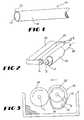
- FIG. 1is a perspective showing of a PTFE green tube used in accordance with the present invention.
- FIG. 2is a perspective showing of an apparatus used to thin the wall of the PTFE green tube of FIG. 1 .
- FIG. 3is an end view of the rollers of the apparatus shown in FIG. 2 .
- FIG. 4is a schematic representation of one embodiment of the method and apparatus of the present invention.
- FIG. 5is a schematic representation of the further embodiment of the method and apparatus of the present invention.
- FIG. 6is a schematic of a still further embodiment of the method and apparatus of the present invention utilizing a first roller and a substantially flat rolling surface.
- FIG. 7is a schematic representation of an additional embodiment of the method and apparatus of the present invention utilizing opposing rolling surfaces.
- FIG. 8is an end view of an embodiment of the present invention utilizing a first roller within a second roller.
- the present inventionprovides a method and apparatus for reducing or thinning the wall and imparting circumferential orientation of a tubular member preferably an extruded PTFE green tube. Furthermore, the present invention provides a product formed by such a method and apparatus where the PTFE green tube has a thinned tubular wall which may be subject to secondary operations such as expansion and sintering to yield an extremely thin-wall biaxially oriented ePTFE.
- Green tube 10is an elongate tubular member having a generally cylindrical tubular wall 12 defining an inner luminal surface 14 and an opposed outer luminal surface 16 .
- Green tube 10may be formed in a conventional wet flow paste extrusion process which is well known in the art. In such a process, a PTFE paste of resin and lubricant is formed in a pre-form press into a tubular pre-form product referred to as a tubular billet.
- the tubular billetis loaded into an extruder and is positioned for entry into a die apparatus.
- the die apparatustypically includes a die cavity with an elongate cylindrical mandrel centered therein.
- the billetis extruded through the die apparatus yielding a generally tubular PTFE green tube.
- the green tube yielded by such a processcontains a certain amount of a low volatility lubricant therein, which as will be described hereinbelow facilitates the operation of the present invention.
- the green tubeis then subjected to secondary operations such as expansion and sintering to yield an expanded polytetrafluoroethylene (ePTFE) tube.
- ePTFEexpanded polytetrafluoroethylene
- Such ePTFE tubehas a thinner wall thickness as a result of the secondary operations and also exhibits a desired porous node and fibril structure which facilitates its use as an implantable medical prosthesis.
- the resultant ePTFE tubewhich has been subjected to such expansion and sintering, has a thinner wall thickness as a result of these operations, the reduction in the wall thickness of the ePTFE tube is limited by the wall thickness of the originally extruded green tube.
- the present inventionprovides for the thinning of the extruded green tube prior to subjecting it to such secondary operations in order to yield a resultant ePTFE tube having a thinner wall thickness and biaxial orientation.
- the roller apparatus 20includes a pair of elongate mandrels or rollers 22 and 24 supported for mutual relative movement towards and away from one another.
- roller 24is a stationary roller mounted to a mounting device 26 .
- Roller 22is a movable roller which is movable in a direction of arrow A towards roller 24 .
- Each of rollers 22 and 24are supported in a manner which permits independent is rotation of the rollers about their longitudinal axes 1 1 , 1 2 .
- the green tubeis positioned concentrically over movable roller 22 so that the outer surface of movable roller 22 contacts the inner surface 14 of green tube 10 .
- Movable roller 22is then moved in the direction of arrow A towards stationary roller 24 to place the outer surface 16 of green tube 10 into contact therewith. Such movement is achieved so as to compress the PTFE green tube 10 between rollers 22 and 24 .
- rollers 22 and 24are caused to counter rotate. Such counter rotation may be achieved by rotating one of the rollers 22 and 24 in a first rotational direction. Inasmuch as frictional engagement is maintained between the movable roller 22 and the stationary roller 24 though green tube 10 , rotation of one of the rollers in one rotational direction will effect counter rotation of the other roller. While direct rotation of only one roller is preferred, it is within the contemplation of the present invention to directly rotate both rollers in a counter rotative manner.
- the green tube 10 supported about movable roller 22Upon the counter rotation of rollers 22 and 24 , the green tube 10 supported about movable roller 22 will be compressed.
- the tubular wall 12will be circuniferentially thinned as it is passed between two rotating rollers. Such thinning of the tubular wall 12 will cause a corresponding increase the inner diameter of green tube 10 .
- As compressive pressure is maintained between the two rollers, continued rotation of the green tube therebetweenwill cause an increasing reduction in the wall thickness, as well as an increase in tube diameter.
- the rolling of the green tube between the rollersis maintained for such a time as is required to achieve the desired reduction in wall thickness.
- the circumferential movement of the green tube between rollers 22 and 24is facilitated by the above-mentioned inclusion of a suitable lubricant, such as isopar in the green tube paste.
- a suitable lubricantsuch as isopar in the green tube paste.
- the lubricantalso assists in preventing longitudinal cracking of the tube.
- the rollers 22 and 24are preferably formed of stainless steel having been machined to eliminate any surface imperfections.
- one or more of the rollersmay be formed of a harder material such as carbide, which resists any distortion during use yielding a more uniform tubular surface.
- the roller apparatus 20may be operated in a heated water bath in order to more effectively thin the green tube. It is contemplated that such bath may be a heated solvent bath having a temperature of between 20° C. and 140° C.
- a roller 40 similar to that shown in FIG. 2is used to compress the tube 10 against a smooth surface 42 .
- surface 42could be a flat surface that is fixably positioned or movably positioned.
- the rotational movement of the tube 10can be accomplished through forcible rotation of roller 40 about axis 1 1 or a sliding movement of surface 42 in directions perpendicular to axis 1 1 providing for passive rotation of cylinder 40 about axis 1 1 .
- the compressive force and frictional engagementwill cause the relative movement of one the roller 40 and Surface 42 . Both forcible rotation and sliding movements could be provided simultaneously. Such relative movement effects the desired thinning and circumferential orienting of the tube 10 .
- the resultant green tubeyields a thin wall ePTFE tube which has improved radial tear strength and creep resistance. Furthermore, by wet cold rolling the green tube at a temperature lower than the melt temperature or softening temperature of the PTFE, the tube becomes easier to handle thereby increasing the yield during the subsequent expansion and sintering thereof.
- the present inventioncontemplates using one or more tensioning rollers in combination with the inner or luminal roller in order to maintain outward radial tension on the green tube as it is being circumferentially thinned between the rollers to eliminate pinching.
- apparatus 120includes rollers 122 and 124 of the type described above.
- Roller 122is the inner or luminal roller and 124 is the outer or external roller. Rotation of roller 122 effects counter rotation of roller 124 .
- the green tube 110is positioned so as to be circumferentially compressed between the counter rotating rollers 122 and 124 . As mentioned above, during this thinning process not only is the wall thickness of the green tube reduced but the diameter of the tube is increased resulting in a larger tube. As the tube is being thinned, there may be a tendency for the slack created by the increasing diameter of the tube to be caught between the rollers.
- tensioning roller 130which may be maintained in outward spring bias relationship with roller 122 .
- the green tube 110is placed over both roller 122 and adjacent tensioning roller 130 .
- the tensioning roller 130provides an outward radial tension within the lumen of tube 110 so as to “take up” slack created by the thinning process.
- Tensioning roller 130may be spring biased outwardly in the direction of arrow B away from roller 122 to maintain such outward radial tension on tube 110 .
- the tensioning roller 130may also facilitate circumferential stretching.
- roller apparatus 220 of FIG. 5includes a pair of exterior rollers 224 positioned on diametrically opposite sides of interior roller 222 .
- the exterior rollers 224compress green tube 210 at two locations on preferably diametrically opposite sides of interior roller 222 .
- Rotation of interior roller 222effects similar mutual counter rotation of both exterior rollers 224 so as to circumferentially compress green tube 210 therebetween.
- a pair of tensioning rollers 230are employed in a manner similar to that described above with respect to FIG. 4 .
- the green tube 210is positioned about roller 222 and adjacent tensioning rollers 230 .
- Two tensioning rollers 230are positioned in apparatus 220 where an oppositely directed outward spring bias is maintained with respect to inner roller 222 .
- Such outward spring biascauses the tensioning rollers 230 to move in a direction of arrow C shown in FIG. 5 .
- the two tensioning rollerswhich are positioned at diametrically opposite ends of roller 222 , maintain outward radial tension on the green tube 210 throughout the thinning process so as to take up any slack which may be created during the thinning process.
- a pair of smooth, flat surfacesare utilized to compress the tube about a roller.
- the green tube 510is positioned about luminal roller 522 and adjacent spaced-apart flat surfaces 50 and 51 .
- the compression and rotationis provided by sliding surface 50 in a direction perpendicular to the axis of roller 522 indicated 1 2 .
- the compressive force and movement of flat surface 50causes the luminal roller 522 to rotate and the tube 510 to contact the surface 51 substantially opposite and parallel to surface 50 and further compress the tube.
- roller apparatus 320 of FIG. 8includes an interior luminal roller 322 positioned within a hollow cylindrical roller 324 .
- the tube 310is mounted on the luminal roller 322 .
- the roller 322is held in tension with the roller 324 thereby providing an outwardly directed compressive force.
- the outwardly directed compressive forcecreates a tread-like friction between the components providing for a circumferential movement of the luminal roller 322 about the inner circumference of the hollow cylinder 324 in the direction of arrow D thereby providing for thinning of the tube.
- a compressive forceis provided in the direction of arrow E, and the rotational force acts as a cog through the frictional engagement of the tube 310 to rotate the hollow cylinder 324 about axis 1 2 providing for thinning of the tube.
- present inventionhas been described specifically with respect to thinning the wall of an extruded PTFE green tube, it is not limited thereto.
- the present inventionmay be used to effect the wall reduction of any resilient tubular member where the tubular wall is subject to reduction from compression.
- compression of the tube to reduce the wall thicknessis preferably achieved by placement of a portion of the tube between two compressing surfaces.
- Other techniques for thinning the tube where the material is thinned by an application of force directly to the materialis also within the contemplation of the present invention.
Landscapes
- Engineering & Computer Science (AREA)
- Mechanical Engineering (AREA)
- Materials For Medical Uses (AREA)
- Casting Or Compression Moulding Of Plastics Or The Like (AREA)
- Extrusion Moulding Of Plastics Or The Like (AREA)
- Shaping By String And By Release Of Stress In Plastics And The Like (AREA)
- Shaping Of Tube Ends By Bending Or Straightening (AREA)
- Prostheses (AREA)
- Rigid Pipes And Flexible Pipes (AREA)
- Laminated Bodies (AREA)
- Apparatuses And Processes For Manufacturing Resistors (AREA)
Abstract
Description
Claims (11)
Priority Applications (10)
| Application Number | Priority Date | Filing Date | Title |
|---|---|---|---|
| US09/748,417US6638468B1 (en) | 2000-12-26 | 2000-12-26 | Method of reducing the wall thickness of a PTFE tube |
| PCT/US2001/048107WO2002051622A2 (en) | 2000-12-26 | 2001-12-11 | Method of reducing the wall thickness of a ptfe tube and product formed thereby |
| ES01990156TES2295232T3 (en) | 2000-12-26 | 2001-12-11 | WALL THICKNESS REDUCTION PROCEDURE OF A PTFE TUBE AND PRODUCT FORMED IN THIS MODE. |
| EP01990156AEP1360048B1 (en) | 2000-12-26 | 2001-12-11 | Method of reducing the wall thickness of a ptfe tube and product formed thereby |
| DE60130259TDE60130259T2 (en) | 2000-12-26 | 2001-12-11 | PROCESS FOR PREVENTING THE WALL THICKNESS OF A PTFE TUBE AND PRODUCT THEREWITH PRODUCED |
| JP2002552745AJP4220239B2 (en) | 2000-12-26 | 2001-12-11 | Method for reducing the wall thickness of a PTFE tube and the product formed by this method |
| CA002436308ACA2436308A1 (en) | 2000-12-26 | 2001-12-11 | Method of reducing the wall thickness of a ptfe tube and product formed thereby |
| AU2002229027AAU2002229027A1 (en) | 2000-12-26 | 2001-12-11 | Method of reducing the wall thickness of a ptfe tube and product formed thereby |
| AT01990156TATE371530T1 (en) | 2000-12-26 | 2001-12-11 | METHOD FOR REDUCING THE WALL THICKNESS OF A PTFE TUBE AND PRODUCT PRODUCED THEREFROM |
| US10/668,517US6939119B2 (en) | 2000-12-26 | 2003-09-23 | Method of reducing the wall thickness of a PTFE tube and product formed thereby |
Applications Claiming Priority (1)
| Application Number | Priority Date | Filing Date | Title |
|---|---|---|---|
| US09/748,417US6638468B1 (en) | 2000-12-26 | 2000-12-26 | Method of reducing the wall thickness of a PTFE tube |
Related Child Applications (1)
| Application Number | Title | Priority Date | Filing Date |
|---|---|---|---|
| US10/668,517DivisionUS6939119B2 (en) | 2000-12-26 | 2003-09-23 | Method of reducing the wall thickness of a PTFE tube and product formed thereby |
Publications (1)
| Publication Number | Publication Date |
|---|---|
| US6638468B1true US6638468B1 (en) | 2003-10-28 |
Family
ID=25009353
Family Applications (2)
| Application Number | Title | Priority Date | Filing Date |
|---|---|---|---|
| US09/748,417Expired - LifetimeUS6638468B1 (en) | 2000-12-26 | 2000-12-26 | Method of reducing the wall thickness of a PTFE tube |
| US10/668,517Expired - Fee RelatedUS6939119B2 (en) | 2000-12-26 | 2003-09-23 | Method of reducing the wall thickness of a PTFE tube and product formed thereby |
Family Applications After (1)
| Application Number | Title | Priority Date | Filing Date |
|---|---|---|---|
| US10/668,517Expired - Fee RelatedUS6939119B2 (en) | 2000-12-26 | 2003-09-23 | Method of reducing the wall thickness of a PTFE tube and product formed thereby |
Country Status (9)
| Country | Link |
|---|---|
| US (2) | US6638468B1 (en) |
| EP (1) | EP1360048B1 (en) |
| JP (1) | JP4220239B2 (en) |
| AT (1) | ATE371530T1 (en) |
| AU (1) | AU2002229027A1 (en) |
| CA (1) | CA2436308A1 (en) |
| DE (1) | DE60130259T2 (en) |
| ES (1) | ES2295232T3 (en) |
| WO (1) | WO2002051622A2 (en) |
Cited By (5)
| Publication number | Priority date | Publication date | Assignee | Title |
|---|---|---|---|---|
| US20020185027A1 (en)* | 2001-06-08 | 2002-12-12 | Udo Drager | Process for manufacturing a sleeve |
| US20040164445A1 (en)* | 2000-11-22 | 2004-08-26 | Bard Peripheral Vascular, Inc | High density microwall expanded polytetrafluoroethylene |
| US7306841B2 (en) | 1999-08-12 | 2007-12-11 | Bridger Biomed, Inc. | PTFE material with aggregations of nodes |
| US20080050570A1 (en)* | 2004-05-13 | 2008-02-28 | Batscap | Method for Treating a Super Capacity Electrode Film in Order to Create Porosity and Associated Machine |
| US8118856B2 (en) | 2009-07-27 | 2012-02-21 | Endologix, Inc. | Stent graft |
Families Citing this family (17)
| Publication number | Priority date | Publication date | Assignee | Title |
|---|---|---|---|---|
| JP4035194B2 (en) | 1996-03-13 | 2008-01-16 | キヤノン株式会社 | X-ray detection apparatus and X-ray detection system |
| CA2425951C (en) | 1999-08-18 | 2008-09-16 | Intrinsic Therapeutics, Inc. | Devices and method for nucleus pulposus augmentation and retention |
| US7553329B2 (en) | 1999-08-18 | 2009-06-30 | Intrinsic Therapeutics, Inc. | Stabilized intervertebral disc barrier |
| US20040010317A1 (en) | 1999-08-18 | 2004-01-15 | Gregory Lambrecht | Devices and method for augmenting a vertebral disc |
| US7717961B2 (en) | 1999-08-18 | 2010-05-18 | Intrinsic Therapeutics, Inc. | Apparatus delivery in an intervertebral disc |
| US7972337B2 (en) | 2005-12-28 | 2011-07-05 | Intrinsic Therapeutics, Inc. | Devices and methods for bone anchoring |
| US7094258B2 (en) | 1999-08-18 | 2006-08-22 | Intrinsic Therapeutics, Inc. | Methods of reinforcing an annulus fibrosis |
| US8323341B2 (en) | 2007-09-07 | 2012-12-04 | Intrinsic Therapeutics, Inc. | Impaction grafting for vertebral fusion |
| US6936072B2 (en) | 1999-08-18 | 2005-08-30 | Intrinsic Therapeutics, Inc. | Encapsulated intervertebral disc prosthesis and methods of manufacture |
| US20040260300A1 (en) | 2003-06-20 | 2004-12-23 | Bogomir Gorensek | Method of delivering an implant through an annular defect in an intervertebral disc |
| US20070162110A1 (en)* | 2006-01-06 | 2007-07-12 | Vipul Bhupendra Dave | Bioabsorbable drug delivery devices |
| US20070158880A1 (en)* | 2006-01-06 | 2007-07-12 | Vipul Bhupendra Dave | Methods of making bioabsorbable drug delivery devices comprised of solvent cast tubes |
| US20070160672A1 (en)* | 2006-01-06 | 2007-07-12 | Vipul Bhupendra Dave | Methods of making bioabsorbable drug delivery devices comprised of solvent cast films |
| US9320837B2 (en)* | 2006-05-12 | 2016-04-26 | CARDINAL HEALTH SWITZERLAND 515 GmbH | Balloon expandable bioabsorbable drug eluting flexible stent |
| US7972373B2 (en)* | 2007-12-19 | 2011-07-05 | Advanced Technologies And Regenerative Medicine, Llc | Balloon expandable bioabsorbable stent with a single stress concentration region interconnecting adjacent struts |
| CN108928008A (en)* | 2018-07-06 | 2018-12-04 | 东莞市宇辰绝缘材料有限公司 | A kind of teflon rod technique |
| CN108908923A (en)* | 2018-07-06 | 2018-11-30 | 东莞市宇辰绝缘材料有限公司 | A kind of polyfluortetraethylene pipe technique |
Citations (12)
| Publication number | Priority date | Publication date | Assignee | Title |
|---|---|---|---|---|
| US2994933A (en) | 1956-04-04 | 1961-08-08 | Sheemon A Wolfe | Grommet |
| US3225129A (en) | 1962-06-26 | 1965-12-21 | Budd Co | Method of making memory re-shaped plastic tubes, especially fluorocarbon cylinder jackets |
| GB1148243A (en) | 1964-11-17 | 1969-04-10 | Fluorodynamics Inc | Method and apparatus for joining web sections of heat sealable film material |
| DE2536358A1 (en) | 1974-08-14 | 1976-02-26 | Canon Kk | Seamless belt prodn. from flat blank - by hot stretching it from a disc to a cylinder |
| US4060577A (en) | 1976-02-11 | 1977-11-29 | Maryland Cup Corporation | Method for producing seamless foam plastic cups from expandable sidewall blanks |
| US4225547A (en) | 1975-12-15 | 1980-09-30 | Sumitomo Electric Industries, Ltd. | Extrusion process of polytetrafluoroethylene tubing materials and apparatus therefor |
| US4530811A (en)* | 1979-06-11 | 1985-07-23 | Plm Aktiebolag | Process for the manufacture of a blank for a container |
| US4613474A (en) | 1984-01-13 | 1986-09-23 | Gino Donati | Procedure and relevant mechanical apparatus to obtain the folding section of a plastic drinking straw |
| US5207960A (en) | 1990-05-30 | 1993-05-04 | Compagnie Plastic Omnium | Method for the manufacture of thin tubes of fluorinated resin, particularly of polytetrafluoroethylene |
| US5346502A (en)* | 1993-04-15 | 1994-09-13 | Ultracision, Inc. | Laparoscopic ultrasonic surgical instrument and methods for manufacturing the instruments |
| US5466509A (en) | 1993-01-15 | 1995-11-14 | Impra, Inc. | Textured, porous, expanded PTFE |
| US5843173A (en) | 1995-04-17 | 1998-12-01 | Baxter International Inc. | Radially-enlargeable PTFE tape-reinforced vascular grafts and their methods of manufacture |
Family Cites Families (6)
| Publication number | Priority date | Publication date | Assignee | Title |
|---|---|---|---|---|
| FR2608096B1 (en)* | 1986-12-15 | 1993-12-24 | Solomat Sa | METHOD AND INSTALLATION FOR EXTRUDING A PRODUCT IN THE FORM OF A FILM, PLATE, TUBE, ROD OR WIRE |
| CA2167943C (en) | 1993-08-18 | 1999-08-17 | Wayne D. House | A thin-wall, seamless, porous polytetrafluoroethylene tube |
| DE4336175C1 (en)* | 1993-10-22 | 1994-10-06 | Juergen Lenzenbach | Process for producing a rotationally symmetrical, thin-walled sheathing |
| US6203735B1 (en) | 1997-02-03 | 2001-03-20 | Impra, Inc. | Method of making expanded polytetrafluoroethylene products |
| US6187054B1 (en) | 1999-02-04 | 2001-02-13 | Endomed Inc. | Method of making large diameter vascular prosteheses and a vascular prosthesis made by said method |
| US6364649B1 (en)* | 1999-10-07 | 2002-04-02 | Fibrex Insulations, Inc. | Apparatus for making pipe insulation |
- 2000
- 2000-12-26USUS09/748,417patent/US6638468B1/ennot_activeExpired - Lifetime
- 2001
- 2001-12-11EPEP01990156Apatent/EP1360048B1/ennot_activeExpired - Lifetime
- 2001-12-11ESES01990156Tpatent/ES2295232T3/ennot_activeExpired - Lifetime
- 2001-12-11WOPCT/US2001/048107patent/WO2002051622A2/enactiveIP Right Grant
- 2001-12-11CACA002436308Apatent/CA2436308A1/ennot_activeAbandoned
- 2001-12-11AUAU2002229027Apatent/AU2002229027A1/ennot_activeAbandoned
- 2001-12-11JPJP2002552745Apatent/JP4220239B2/ennot_activeExpired - Fee Related
- 2001-12-11ATAT01990156Tpatent/ATE371530T1/ennot_activeIP Right Cessation
- 2001-12-11DEDE60130259Tpatent/DE60130259T2/ennot_activeExpired - Lifetime
- 2003
- 2003-09-23USUS10/668,517patent/US6939119B2/ennot_activeExpired - Fee Related
Patent Citations (12)
| Publication number | Priority date | Publication date | Assignee | Title |
|---|---|---|---|---|
| US2994933A (en) | 1956-04-04 | 1961-08-08 | Sheemon A Wolfe | Grommet |
| US3225129A (en) | 1962-06-26 | 1965-12-21 | Budd Co | Method of making memory re-shaped plastic tubes, especially fluorocarbon cylinder jackets |
| GB1148243A (en) | 1964-11-17 | 1969-04-10 | Fluorodynamics Inc | Method and apparatus for joining web sections of heat sealable film material |
| DE2536358A1 (en) | 1974-08-14 | 1976-02-26 | Canon Kk | Seamless belt prodn. from flat blank - by hot stretching it from a disc to a cylinder |
| US4225547A (en) | 1975-12-15 | 1980-09-30 | Sumitomo Electric Industries, Ltd. | Extrusion process of polytetrafluoroethylene tubing materials and apparatus therefor |
| US4060577A (en) | 1976-02-11 | 1977-11-29 | Maryland Cup Corporation | Method for producing seamless foam plastic cups from expandable sidewall blanks |
| US4530811A (en)* | 1979-06-11 | 1985-07-23 | Plm Aktiebolag | Process for the manufacture of a blank for a container |
| US4613474A (en) | 1984-01-13 | 1986-09-23 | Gino Donati | Procedure and relevant mechanical apparatus to obtain the folding section of a plastic drinking straw |
| US5207960A (en) | 1990-05-30 | 1993-05-04 | Compagnie Plastic Omnium | Method for the manufacture of thin tubes of fluorinated resin, particularly of polytetrafluoroethylene |
| US5466509A (en) | 1993-01-15 | 1995-11-14 | Impra, Inc. | Textured, porous, expanded PTFE |
| US5346502A (en)* | 1993-04-15 | 1994-09-13 | Ultracision, Inc. | Laparoscopic ultrasonic surgical instrument and methods for manufacturing the instruments |
| US5843173A (en) | 1995-04-17 | 1998-12-01 | Baxter International Inc. | Radially-enlargeable PTFE tape-reinforced vascular grafts and their methods of manufacture |
Cited By (9)
| Publication number | Priority date | Publication date | Assignee | Title |
|---|---|---|---|---|
| US7306841B2 (en) | 1999-08-12 | 2007-12-11 | Bridger Biomed, Inc. | PTFE material with aggregations of nodes |
| US20040164445A1 (en)* | 2000-11-22 | 2004-08-26 | Bard Peripheral Vascular, Inc | High density microwall expanded polytetrafluoroethylene |
| US7226558B2 (en) | 2000-11-22 | 2007-06-05 | Bard Peripheral Vascular, Inc. | Method of making an expanded polytetrafluoroethylene structure |
| US20020185027A1 (en)* | 2001-06-08 | 2002-12-12 | Udo Drager | Process for manufacturing a sleeve |
| US20080050570A1 (en)* | 2004-05-13 | 2008-02-28 | Batscap | Method for Treating a Super Capacity Electrode Film in Order to Create Porosity and Associated Machine |
| US8118856B2 (en) | 2009-07-27 | 2012-02-21 | Endologix, Inc. | Stent graft |
| US8821564B2 (en) | 2009-07-27 | 2014-09-02 | Endologix, Inc. | Stent graft |
| US9907642B2 (en) | 2009-07-27 | 2018-03-06 | Endologix, Inc. | Stent graft |
| US10874502B2 (en) | 2009-07-27 | 2020-12-29 | Endologix Llc | Stent graft |
Also Published As
| Publication number | Publication date |
|---|---|
| JP4220239B2 (en) | 2009-02-04 |
| DE60130259D1 (en) | 2007-10-11 |
| WO2002051622A3 (en) | 2003-04-03 |
| EP1360048B1 (en) | 2007-08-29 |
| CA2436308A1 (en) | 2002-07-04 |
| ES2295232T3 (en) | 2008-04-16 |
| ATE371530T1 (en) | 2007-09-15 |
| WO2002051622A2 (en) | 2002-07-04 |
| EP1360048A2 (en) | 2003-11-12 |
| AU2002229027A1 (en) | 2002-07-08 |
| DE60130259T2 (en) | 2008-12-24 |
| US6939119B2 (en) | 2005-09-06 |
| US20040056384A1 (en) | 2004-03-25 |
| JP2004535947A (en) | 2004-12-02 |
Similar Documents
| Publication | Publication Date | Title |
|---|---|---|
| US6638468B1 (en) | Method of reducing the wall thickness of a PTFE tube | |
| EP0778753B1 (en) | Method of making an asymmetrical porous ptfe form | |
| JP4065319B2 (en) | Method for forming PTFE tube | |
| CA2497702C (en) | Eptfe crimped graft | |
| CA1046433A (en) | Porous polytetrafluoroethylene tubings and process of producing them | |
| US6187054B1 (en) | Method of making large diameter vascular prosteheses and a vascular prosthesis made by said method | |
| EP0821648B1 (en) | Methods of manufacture of radially-enlargeable ptfe tape-reinforced vascular grafts | |
| US5928279A (en) | Stented, radially expandable, tubular PTFE grafts | |
| US20210260252A1 (en) | Puncturable and resealable graft | |
| US3225129A (en) | Method of making memory re-shaped plastic tubes, especially fluorocarbon cylinder jackets | |
| EP0714345A1 (en) | A thin-wall, seamless, porous polytetrafluoroethylene tube | |
| EP0750481A1 (en) | Reinforced vascular graft and method of making same | |
| JP2005507709A5 (en) | ||
| US6616876B1 (en) | Method for treating expandable polymer materials | |
| EP1741544A3 (en) | Method of making expanded polytetrafluoroethylene products | |
| US20090252926A1 (en) | Thin-walled calendered ptfe | |
| US7806922B2 (en) | Sintered ring supported vascular graft | |
| FR2679484A1 (en) | PROCESS FOR THE PRODUCTION OF TUBES IN FLUORINATED RESIN, IN PARTICULAR IN POLYTETRAFLUORETHYLENE. | |
| US8226875B2 (en) | Extremely thin-walled ePTFE | |
| EP1486268A1 (en) | Method for the production of tubular structures with a gradually changing inner diameter | |
| US8298462B2 (en) | Method of uniaxially expanding a fluoropolymer product |
Legal Events
| Date | Code | Title | Description |
|---|---|---|---|
| AS | Assignment | Owner name:SCIMED LIFE SYSTEMS, INC., MINNESOTA Free format text:ASSIGNMENT OF ASSIGNORS INTEREST;ASSIGNORS:HILL, JASON P.;LININGER, JAMES R.;BROWN, BRIAN J.;REEL/FRAME:011412/0871;SIGNING DATES FROM 20001211 TO 20001221 | |
| FEPP | Fee payment procedure | Free format text:PAYER NUMBER DE-ASSIGNED (ORIGINAL EVENT CODE: RMPN); ENTITY STATUS OF PATENT OWNER: LARGE ENTITY Free format text:PAYOR NUMBER ASSIGNED (ORIGINAL EVENT CODE: ASPN); ENTITY STATUS OF PATENT OWNER: LARGE ENTITY | |
| STCF | Information on status: patent grant | Free format text:PATENTED CASE | |
| CC | Certificate of correction | ||
| AS | Assignment | Owner name:BOSTON SCIENTIFIC SCIMED, INC., MINNESOTA Free format text:CHANGE OF NAME;ASSIGNOR:SCIMED LIFE SYSTEMS, INC.;REEL/FRAME:018505/0868 Effective date:20050101 Owner name:BOSTON SCIENTIFIC SCIMED, INC.,MINNESOTA Free format text:CHANGE OF NAME;ASSIGNOR:SCIMED LIFE SYSTEMS, INC.;REEL/FRAME:018505/0868 Effective date:20050101 | |
| FPAY | Fee payment | Year of fee payment:4 | |
| FPAY | Fee payment | Year of fee payment:8 | |
| AS | Assignment | Owner name:ACACIA RESEARCH GROUP LLC, TEXAS Free format text:ASSIGNMENT OF ASSIGNORS INTEREST;ASSIGNOR:BOSTON SCIENTIFIC SCIMED, INC.;REEL/FRAME:030694/0461 Effective date:20121220 | |
| AS | Assignment | Owner name:LIFESHIELD SCIENCES LLC, TEXAS Free format text:ASSIGNMENT OF ASSIGNORS INTEREST;ASSIGNOR:ACACIA RESEARCH GROUP LLC;REEL/FRAME:030740/0225 Effective date:20130515 | |
| FPAY | Fee payment | Year of fee payment:12 |