US6638301B1 - Medical device with radiopacity - Google Patents
Medical device with radiopacityDownload PDFInfo
- Publication number
- US6638301B1 US6638301B1US10/263,212US26321202AUS6638301B1US 6638301 B1US6638301 B1US 6638301B1US 26321202 AUS26321202 AUS 26321202AUS 6638301 B1US6638301 B1US 6638301B1
- Authority
- US
- United States
- Prior art keywords
- stent
- layer
- radiopaque
- radiopaque material
- gold
- Prior art date
- Legal status (The legal status is an assumption and is not a legal conclusion. Google has not performed a legal analysis and makes no representation as to the accuracy of the status listed.)
- Expired - Lifetime
Links
- 239000010410layerSubstances0.000claimsdescription157
- 239000000463materialSubstances0.000claimsdescription119
- 239000010931goldSubstances0.000claimsdescription23
- PCHJSUWPFVWCPO-UHFFFAOYSA-NgoldChemical compound[Au]PCHJSUWPFVWCPO-UHFFFAOYSA-N0.000claimsdescription21
- 229910052737goldInorganic materials0.000claimsdescription21
- KDLHZDBZIXYQEI-UHFFFAOYSA-NPalladiumChemical compound[Pd]KDLHZDBZIXYQEI-UHFFFAOYSA-N0.000claimsdescription20
- BASFCYQUMIYNBI-UHFFFAOYSA-NplatinumChemical compound[Pt]BASFCYQUMIYNBI-UHFFFAOYSA-N0.000claimsdescription20
- 239000010936titaniumSubstances0.000claimsdescription19
- 239000000956alloySubstances0.000claimsdescription17
- 229910045601alloyInorganic materials0.000claimsdescription16
- 229910052719titaniumInorganic materials0.000claimsdescription16
- RTAQQCXQSZGOHL-UHFFFAOYSA-NTitaniumChemical compound[Ti]RTAQQCXQSZGOHL-UHFFFAOYSA-N0.000claimsdescription15
- 230000003647oxidationEffects0.000claimsdescription10
- 238000007254oxidation reactionMethods0.000claimsdescription10
- 229910052763palladiumInorganic materials0.000claimsdescription10
- 229910052697platinumInorganic materials0.000claimsdescription10
- 229910001000nickel titaniumInorganic materials0.000claimsdescription9
- 239000010935stainless steelSubstances0.000claimsdescription9
- 229910001220stainless steelInorganic materials0.000claimsdescription8
- 229910052715tantalumInorganic materials0.000claimsdescription8
- GUVRBAGPIYLISA-UHFFFAOYSA-Ntantalum atomChemical compound[Ta]GUVRBAGPIYLISA-UHFFFAOYSA-N0.000claimsdescription8
- 239000003814drugSubstances0.000claimsdescription6
- 239000000203mixtureSubstances0.000claimsdescription6
- 239000011651chromiumSubstances0.000claimsdescription5
- VYZAMTAEIAYCRO-UHFFFAOYSA-NChromiumChemical compound[Cr]VYZAMTAEIAYCRO-UHFFFAOYSA-N0.000claimsdescription4
- XUIMIQQOPSSXEZ-UHFFFAOYSA-NSiliconChemical compound[Si]XUIMIQQOPSSXEZ-UHFFFAOYSA-N0.000claimsdescription4
- 229910052804chromiumInorganic materials0.000claimsdescription4
- 229940079593drugDrugs0.000claimsdescription4
- 229910052758niobiumInorganic materials0.000claimsdescription4
- 239000010955niobiumSubstances0.000claimsdescription4
- GUCVJGMIXFAOAE-UHFFFAOYSA-Nniobium atomChemical compound[Nb]GUCVJGMIXFAOAE-UHFFFAOYSA-N0.000claimsdescription4
- 239000013047polymeric layerSubstances0.000claimsdescription4
- 229910052710siliconInorganic materials0.000claimsdescription4
- 239000010703siliconSubstances0.000claimsdescription4
- 238000000034methodMethods0.000abstractdescription25
- 239000011162core materialSubstances0.000description17
- 238000005275alloyingMethods0.000description12
- -1Au0.30Ti0.70Chemical compound0.000description9
- 238000007735ion beam assisted depositionMethods0.000description9
- 230000008569processEffects0.000description8
- ZNKMCMOJCDFGFT-UHFFFAOYSA-Ngold titaniumChemical compound[Ti].[Au]ZNKMCMOJCDFGFT-UHFFFAOYSA-N0.000description7
- 229910001258titanium goldInorganic materials0.000description7
- XKRFYHLGVUSROY-UHFFFAOYSA-NArgonChemical compound[Ar]XKRFYHLGVUSROY-UHFFFAOYSA-N0.000description6
- 238000000151depositionMethods0.000description6
- 230000001590oxidative effectEffects0.000description6
- 238000000137annealingMethods0.000description5
- 238000010438heat treatmentMethods0.000description5
- 238000010884ion-beam techniqueMethods0.000description5
- 150000002500ionsChemical class0.000description5
- HLXZNVUGXRDIFK-UHFFFAOYSA-Nnickel titaniumChemical compound[Ti].[Ti].[Ti].[Ti].[Ti].[Ti].[Ti].[Ti].[Ti].[Ti].[Ti].[Ni].[Ni].[Ni].[Ni].[Ni].[Ni].[Ni].[Ni].[Ni].[Ni].[Ni].[Ni].[Ni].[Ni]HLXZNVUGXRDIFK-UHFFFAOYSA-N0.000description5
- 150000004767nitridesChemical class0.000description5
- 239000013078crystalSubstances0.000description4
- 230000008021depositionEffects0.000description4
- 238000009792diffusion processMethods0.000description4
- 238000005240physical vapour depositionMethods0.000description4
- 229910052692DysprosiumInorganic materials0.000description3
- 229910052688GadoliniumInorganic materials0.000description3
- KFZMGEQAYNKOFK-UHFFFAOYSA-NIsopropanolChemical compoundCC(C)OKFZMGEQAYNKOFK-UHFFFAOYSA-N0.000description3
- 229910052786argonInorganic materials0.000description3
- 239000012298atmosphereSubstances0.000description3
- 238000005229chemical vapour depositionMethods0.000description3
- 238000004140cleaningMethods0.000description3
- KBQHZAAAGSGFKK-UHFFFAOYSA-Ndysprosium atomChemical compound[Dy]KBQHZAAAGSGFKK-UHFFFAOYSA-N0.000description3
- 238000004070electrodepositionMethods0.000description3
- 238000010894electron beam technologyMethods0.000description3
- UIWYJDYFSGRHKR-UHFFFAOYSA-Ngadolinium atomChemical compound[Gd]UIWYJDYFSGRHKR-UHFFFAOYSA-N0.000description3
- 238000002161passivationMethods0.000description3
- 229920001343polytetrafluoroethylenePolymers0.000description3
- 239000004810polytetrafluoroethyleneSubstances0.000description3
- 239000000758substrateSubstances0.000description3
- CSCPPACGZOOCGX-UHFFFAOYSA-NAcetoneChemical compoundCC(C)=OCSCPPACGZOOCGX-UHFFFAOYSA-N0.000description2
- QGZKDVFQNNGYKY-UHFFFAOYSA-NAmmoniaChemical compoundNQGZKDVFQNNGYKY-UHFFFAOYSA-N0.000description2
- IJGRMHOSHXDMSA-UHFFFAOYSA-NAtomic nitrogenChemical compoundN#NIJGRMHOSHXDMSA-UHFFFAOYSA-N0.000description2
- OKTJSMMVPCPJKN-UHFFFAOYSA-NCarbonChemical compound[C]OKTJSMMVPCPJKN-UHFFFAOYSA-N0.000description2
- CWYNVVGOOAEACU-UHFFFAOYSA-NFe2+Chemical compound[Fe+2]CWYNVVGOOAEACU-UHFFFAOYSA-N0.000description2
- 229910001069Ti alloyInorganic materials0.000description2
- 238000010521absorption reactionMethods0.000description2
- QVGXLLKOCUKJST-UHFFFAOYSA-Natomic oxygenChemical compound[O]QVGXLLKOCUKJST-UHFFFAOYSA-N0.000description2
- 239000011248coating agentSubstances0.000description2
- 238000000576coating methodMethods0.000description2
- 150000001875compoundsChemical class0.000description2
- 238000007796conventional methodMethods0.000description2
- SZVJSHCCFOBDDC-UHFFFAOYSA-Nferrosoferric oxideChemical compoundO=[Fe]O[Fe]O[Fe]=OSZVJSHCCFOBDDC-UHFFFAOYSA-N0.000description2
- 239000007789gasSubstances0.000description2
- JUWSSMXCCAMYGX-UHFFFAOYSA-Ngold platinumChemical compound[Pt].[Au]JUWSSMXCCAMYGX-UHFFFAOYSA-N0.000description2
- 229910052741iridiumInorganic materials0.000description2
- GKOZUEZYRPOHIO-UHFFFAOYSA-Niridium atomChemical compound[Ir]GKOZUEZYRPOHIO-UHFFFAOYSA-N0.000description2
- 230000007246mechanismEffects0.000description2
- 229910001092metal group alloyInorganic materials0.000description2
- VNWKTOKETHGBQD-UHFFFAOYSA-NmethaneChemical compoundCVNWKTOKETHGBQD-UHFFFAOYSA-N0.000description2
- 239000001301oxygenSubstances0.000description2
- 229910052760oxygenInorganic materials0.000description2
- 238000004544sputter depositionMethods0.000description2
- 229940124597therapeutic agentDrugs0.000description2
- XLYOFNOQVPJJNP-UHFFFAOYSA-NwaterSubstancesOXLYOFNOQVPJJNP-UHFFFAOYSA-N0.000description2
- 206010002329AneurysmDiseases0.000description1
- 239000004215Carbon black (E152)Substances0.000description1
- 229910002518CoFe2O4Inorganic materials0.000description1
- RYGMFSIKBFXOCR-UHFFFAOYSA-NCopperChemical compound[Cu]RYGMFSIKBFXOCR-UHFFFAOYSA-N0.000description1
- JOYRKODLDBILNP-UHFFFAOYSA-NEthyl urethaneChemical compoundCCOC(N)=OJOYRKODLDBILNP-UHFFFAOYSA-N0.000description1
- 206010061218InflammationDiseases0.000description1
- 229910017163MnFe2O4Inorganic materials0.000description1
- 229910001257Nb alloyInorganic materials0.000description1
- 206010028980NeoplasmDiseases0.000description1
- 239000004698PolyethyleneSubstances0.000description1
- 239000004743PolypropyleneSubstances0.000description1
- BQCADISMDOOEFD-UHFFFAOYSA-NSilverChemical compound[Ag]BQCADISMDOOEFD-UHFFFAOYSA-N0.000description1
- 229910001362Ta alloysInorganic materials0.000description1
- QCWXUUIWCKQGHC-UHFFFAOYSA-NZirconiumChemical compound[Zr]QCWXUUIWCKQGHC-UHFFFAOYSA-N0.000description1
- 229910001093Zr alloyInorganic materials0.000description1
- MOSURRVHVKOQHA-UHFFFAOYSA-N[Tb].[Dy]Chemical compound[Tb].[Dy]MOSURRVHVKOQHA-UHFFFAOYSA-N0.000description1
- 238000013019agitationMethods0.000description1
- 229910021529ammoniaInorganic materials0.000description1
- 239000003242anti bacterial agentSubstances0.000description1
- 229940121363anti-inflammatory agentDrugs0.000description1
- 239000002260anti-inflammatory agentSubstances0.000description1
- 229940088710antibiotic agentDrugs0.000description1
- 239000003146anticoagulant agentSubstances0.000description1
- 229940127219anticoagulant drugDrugs0.000description1
- 239000003963antioxidant agentSubstances0.000description1
- 210000001367arteryAnatomy0.000description1
- 210000004204blood vesselAnatomy0.000description1
- 229910052799carbonInorganic materials0.000description1
- 238000005255carburizingMethods0.000description1
- 230000008859changeEffects0.000description1
- 238000006243chemical reactionMethods0.000description1
- 239000010941cobaltSubstances0.000description1
- 229910017052cobaltInorganic materials0.000description1
- GUTLYIVDDKVIGB-UHFFFAOYSA-Ncobalt atomChemical compound[Co]GUTLYIVDDKVIGB-UHFFFAOYSA-N0.000description1
- 239000002131composite materialSubstances0.000description1
- 229910052802copperInorganic materials0.000description1
- 239000010949copperSubstances0.000description1
- 230000007797corrosionEffects0.000description1
- 238000005260corrosionMethods0.000description1
- 239000013527degreasing agentSubstances0.000description1
- 239000008367deionised waterSubstances0.000description1
- 229910021641deionized waterInorganic materials0.000description1
- 230000001419dependent effectEffects0.000description1
- 238000010586diagramMethods0.000description1
- 238000007598dipping methodMethods0.000description1
- NLQFUUYNQFMIJW-UHFFFAOYSA-Ndysprosium(III) oxideInorganic materialsO=[Dy]O[Dy]=ONLQFUUYNQFMIJW-UHFFFAOYSA-N0.000description1
- 239000013013elastic materialSubstances0.000description1
- 239000003527fibrinolytic agentSubstances0.000description1
- 239000010408filmSubstances0.000description1
- 238000002594fluoroscopyMethods0.000description1
- CMIHHWBVHJVIGI-UHFFFAOYSA-Ngadolinium(III) oxideInorganic materials[O-2].[O-2].[O-2].[Gd+3].[Gd+3]CMIHHWBVHJVIGI-UHFFFAOYSA-N0.000description1
- 238000005246galvanizingMethods0.000description1
- 239000003193general anesthetic agentSubstances0.000description1
- 229910002804graphiteInorganic materials0.000description1
- 239000010439graphiteSubstances0.000description1
- 229930195733hydrocarbonNatural products0.000description1
- 150000002430hydrocarbonsChemical class0.000description1
- 239000001257hydrogenSubstances0.000description1
- 229910052739hydrogenInorganic materials0.000description1
- 239000007943implantSubstances0.000description1
- 238000002513implantationMethods0.000description1
- 230000004054inflammatory processEffects0.000description1
- 229910052742ironInorganic materials0.000description1
- 230000007774longtermEffects0.000description1
- 230000005291magnetic effectEffects0.000description1
- 238000002595magnetic resonance imagingMethods0.000description1
- 238000004519manufacturing processMethods0.000description1
- 239000011159matrix materialSubstances0.000description1
- 229910052751metalInorganic materials0.000description1
- 239000002184metalSubstances0.000description1
- 150000001247metal acetylidesChemical class0.000description1
- 239000012768molten materialSubstances0.000description1
- 239000002105nanoparticleSubstances0.000description1
- 229910052759nickelInorganic materials0.000description1
- 229910052757nitrogenInorganic materials0.000description1
- 230000000399orthopedic effectEffects0.000description1
- 230000010355oscillationEffects0.000description1
- 230000005298paramagnetic effectEffects0.000description1
- UUWCBFKLGFQDME-UHFFFAOYSA-Nplatinum titaniumChemical compound[Ti].[Pt]UUWCBFKLGFQDME-UHFFFAOYSA-N0.000description1
- 229920000573polyethylenePolymers0.000description1
- 229920000642polymerPolymers0.000description1
- 229920001155polypropylenePolymers0.000description1
- 239000010453quartzSubstances0.000description1
- 230000027756respiratory electron transport chainEffects0.000description1
- 230000000452restraining effectEffects0.000description1
- 229910052703rhodiumInorganic materials0.000description1
- 239000010948rhodiumSubstances0.000description1
- MHOVAHRLVXNVSD-UHFFFAOYSA-Nrhodium atomChemical compound[Rh]MHOVAHRLVXNVSD-UHFFFAOYSA-N0.000description1
- VYPSYNLAJGMNEJ-UHFFFAOYSA-Nsilicon dioxideInorganic materialsO=[Si]=OVYPSYNLAJGMNEJ-UHFFFAOYSA-N0.000description1
- 229910052709silverInorganic materials0.000description1
- 239000004332silverSubstances0.000description1
- 239000002904solventSubstances0.000description1
- 229910001256stainless steel alloyInorganic materials0.000description1
- 239000002344surface layerSubstances0.000description1
- 238000002207thermal evaporationMethods0.000description1
- 239000010409thin filmSubstances0.000description1
- 230000007704transitionEffects0.000description1
- 229910000314transition metal oxideInorganic materials0.000description1
- WFKWXMTUELFFGS-UHFFFAOYSA-NtungstenChemical compound[W]WFKWXMTUELFFGS-UHFFFAOYSA-N0.000description1
- 229910052721tungstenInorganic materials0.000description1
- 239000010937tungstenSubstances0.000description1
- 229910052726zirconiumInorganic materials0.000description1
Images


Classifications
- C—CHEMISTRY; METALLURGY
- C23—COATING METALLIC MATERIAL; COATING MATERIAL WITH METALLIC MATERIAL; CHEMICAL SURFACE TREATMENT; DIFFUSION TREATMENT OF METALLIC MATERIAL; COATING BY VACUUM EVAPORATION, BY SPUTTERING, BY ION IMPLANTATION OR BY CHEMICAL VAPOUR DEPOSITION, IN GENERAL; INHIBITING CORROSION OF METALLIC MATERIAL OR INCRUSTATION IN GENERAL
- C23C—COATING METALLIC MATERIAL; COATING MATERIAL WITH METALLIC MATERIAL; SURFACE TREATMENT OF METALLIC MATERIAL BY DIFFUSION INTO THE SURFACE, BY CHEMICAL CONVERSION OR SUBSTITUTION; COATING BY VACUUM EVAPORATION, BY SPUTTERING, BY ION IMPLANTATION OR BY CHEMICAL VAPOUR DEPOSITION, IN GENERAL
- C23C8/00—Solid state diffusion of only non-metal elements into metallic material surfaces; Chemical surface treatment of metallic material by reaction of the surface with a reactive gas, leaving reaction products of surface material in the coating, e.g. conversion coatings, passivation of metals
- C23C8/06—Solid state diffusion of only non-metal elements into metallic material surfaces; Chemical surface treatment of metallic material by reaction of the surface with a reactive gas, leaving reaction products of surface material in the coating, e.g. conversion coatings, passivation of metals using gases
- C23C8/08—Solid state diffusion of only non-metal elements into metallic material surfaces; Chemical surface treatment of metallic material by reaction of the surface with a reactive gas, leaving reaction products of surface material in the coating, e.g. conversion coatings, passivation of metals using gases only one element being applied
- C23C8/10—Oxidising
- A—HUMAN NECESSITIES
- A61—MEDICAL OR VETERINARY SCIENCE; HYGIENE
- A61F—FILTERS IMPLANTABLE INTO BLOOD VESSELS; PROSTHESES; DEVICES PROVIDING PATENCY TO, OR PREVENTING COLLAPSING OF, TUBULAR STRUCTURES OF THE BODY, e.g. STENTS; ORTHOPAEDIC, NURSING OR CONTRACEPTIVE DEVICES; FOMENTATION; TREATMENT OR PROTECTION OF EYES OR EARS; BANDAGES, DRESSINGS OR ABSORBENT PADS; FIRST-AID KITS
- A61F2/00—Filters implantable into blood vessels; Prostheses, i.e. artificial substitutes or replacements for parts of the body; Appliances for connecting them with the body; Devices providing patency to, or preventing collapsing of, tubular structures of the body, e.g. stents
- A61F2/82—Devices providing patency to, or preventing collapsing of, tubular structures of the body, e.g. stents
- A61F2/86—Stents in a form characterised by the wire-like elements; Stents in the form characterised by a net-like or mesh-like structure
- A61F2/90—Stents in a form characterised by the wire-like elements; Stents in the form characterised by a net-like or mesh-like structure characterised by a net-like or mesh-like structure
- A61F2/91—Stents in a form characterised by the wire-like elements; Stents in the form characterised by a net-like or mesh-like structure characterised by a net-like or mesh-like structure made from perforated sheets or tubes, e.g. perforated by laser cuts or etched holes
- A61F2/915—Stents in a form characterised by the wire-like elements; Stents in the form characterised by a net-like or mesh-like structure characterised by a net-like or mesh-like structure made from perforated sheets or tubes, e.g. perforated by laser cuts or etched holes with bands having a meander structure, adjacent bands being connected to each other
- A—HUMAN NECESSITIES
- A61—MEDICAL OR VETERINARY SCIENCE; HYGIENE
- A61L—METHODS OR APPARATUS FOR STERILISING MATERIALS OR OBJECTS IN GENERAL; DISINFECTION, STERILISATION OR DEODORISATION OF AIR; CHEMICAL ASPECTS OF BANDAGES, DRESSINGS, ABSORBENT PADS OR SURGICAL ARTICLES; MATERIALS FOR BANDAGES, DRESSINGS, ABSORBENT PADS OR SURGICAL ARTICLES
- A61L31/00—Materials for other surgical articles, e.g. stents, stent-grafts, shunts, surgical drapes, guide wires, materials for adhesion prevention, occluding devices, surgical gloves, tissue fixation devices
- A61L31/08—Materials for coatings
- A61L31/082—Inorganic materials
- A61L31/088—Other specific inorganic materials not covered by A61L31/084 or A61L31/086
- A—HUMAN NECESSITIES
- A61—MEDICAL OR VETERINARY SCIENCE; HYGIENE
- A61L—METHODS OR APPARATUS FOR STERILISING MATERIALS OR OBJECTS IN GENERAL; DISINFECTION, STERILISATION OR DEODORISATION OF AIR; CHEMICAL ASPECTS OF BANDAGES, DRESSINGS, ABSORBENT PADS OR SURGICAL ARTICLES; MATERIALS FOR BANDAGES, DRESSINGS, ABSORBENT PADS OR SURGICAL ARTICLES
- A61L31/00—Materials for other surgical articles, e.g. stents, stent-grafts, shunts, surgical drapes, guide wires, materials for adhesion prevention, occluding devices, surgical gloves, tissue fixation devices
- A61L31/14—Materials characterised by their function or physical properties, e.g. injectable or lubricating compositions, shape-memory materials, surface modified materials
- A61L31/18—Materials at least partially X-ray or laser opaque
- C—CHEMISTRY; METALLURGY
- C23—COATING METALLIC MATERIAL; COATING MATERIAL WITH METALLIC MATERIAL; CHEMICAL SURFACE TREATMENT; DIFFUSION TREATMENT OF METALLIC MATERIAL; COATING BY VACUUM EVAPORATION, BY SPUTTERING, BY ION IMPLANTATION OR BY CHEMICAL VAPOUR DEPOSITION, IN GENERAL; INHIBITING CORROSION OF METALLIC MATERIAL OR INCRUSTATION IN GENERAL
- C23C—COATING METALLIC MATERIAL; COATING MATERIAL WITH METALLIC MATERIAL; SURFACE TREATMENT OF METALLIC MATERIAL BY DIFFUSION INTO THE SURFACE, BY CHEMICAL CONVERSION OR SUBSTITUTION; COATING BY VACUUM EVAPORATION, BY SPUTTERING, BY ION IMPLANTATION OR BY CHEMICAL VAPOUR DEPOSITION, IN GENERAL
- C23C14/00—Coating by vacuum evaporation, by sputtering or by ion implantation of the coating forming material
- C23C14/06—Coating by vacuum evaporation, by sputtering or by ion implantation of the coating forming material characterised by the coating material
- C23C14/14—Metallic material, boron or silicon
- C23C14/16—Metallic material, boron or silicon on metallic substrates or on substrates of boron or silicon
- C—CHEMISTRY; METALLURGY
- C23—COATING METALLIC MATERIAL; COATING MATERIAL WITH METALLIC MATERIAL; CHEMICAL SURFACE TREATMENT; DIFFUSION TREATMENT OF METALLIC MATERIAL; COATING BY VACUUM EVAPORATION, BY SPUTTERING, BY ION IMPLANTATION OR BY CHEMICAL VAPOUR DEPOSITION, IN GENERAL; INHIBITING CORROSION OF METALLIC MATERIAL OR INCRUSTATION IN GENERAL
- C23C—COATING METALLIC MATERIAL; COATING MATERIAL WITH METALLIC MATERIAL; SURFACE TREATMENT OF METALLIC MATERIAL BY DIFFUSION INTO THE SURFACE, BY CHEMICAL CONVERSION OR SUBSTITUTION; COATING BY VACUUM EVAPORATION, BY SPUTTERING, BY ION IMPLANTATION OR BY CHEMICAL VAPOUR DEPOSITION, IN GENERAL
- C23C14/00—Coating by vacuum evaporation, by sputtering or by ion implantation of the coating forming material
- C23C14/22—Coating by vacuum evaporation, by sputtering or by ion implantation of the coating forming material characterised by the process of coating
- C23C14/34—Sputtering
- C23C14/46—Sputtering by ion beam produced by an external ion source
- C—CHEMISTRY; METALLURGY
- C23—COATING METALLIC MATERIAL; COATING MATERIAL WITH METALLIC MATERIAL; CHEMICAL SURFACE TREATMENT; DIFFUSION TREATMENT OF METALLIC MATERIAL; COATING BY VACUUM EVAPORATION, BY SPUTTERING, BY ION IMPLANTATION OR BY CHEMICAL VAPOUR DEPOSITION, IN GENERAL; INHIBITING CORROSION OF METALLIC MATERIAL OR INCRUSTATION IN GENERAL
- C23C—COATING METALLIC MATERIAL; COATING MATERIAL WITH METALLIC MATERIAL; SURFACE TREATMENT OF METALLIC MATERIAL BY DIFFUSION INTO THE SURFACE, BY CHEMICAL CONVERSION OR SUBSTITUTION; COATING BY VACUUM EVAPORATION, BY SPUTTERING, BY ION IMPLANTATION OR BY CHEMICAL VAPOUR DEPOSITION, IN GENERAL
- C23C28/00—Coating for obtaining at least two superposed coatings either by methods not provided for in a single one of groups C23C2/00 - C23C26/00 or by combinations of methods provided for in subclasses C23C and C25C or C25D
- C23C28/02—Coating for obtaining at least two superposed coatings either by methods not provided for in a single one of groups C23C2/00 - C23C26/00 or by combinations of methods provided for in subclasses C23C and C25C or C25D only coatings only including layers of metallic material
- C23C28/021—Coating for obtaining at least two superposed coatings either by methods not provided for in a single one of groups C23C2/00 - C23C26/00 or by combinations of methods provided for in subclasses C23C and C25C or C25D only coatings only including layers of metallic material including at least one metal alloy layer
- C—CHEMISTRY; METALLURGY
- C23—COATING METALLIC MATERIAL; COATING MATERIAL WITH METALLIC MATERIAL; CHEMICAL SURFACE TREATMENT; DIFFUSION TREATMENT OF METALLIC MATERIAL; COATING BY VACUUM EVAPORATION, BY SPUTTERING, BY ION IMPLANTATION OR BY CHEMICAL VAPOUR DEPOSITION, IN GENERAL; INHIBITING CORROSION OF METALLIC MATERIAL OR INCRUSTATION IN GENERAL
- C23C—COATING METALLIC MATERIAL; COATING MATERIAL WITH METALLIC MATERIAL; SURFACE TREATMENT OF METALLIC MATERIAL BY DIFFUSION INTO THE SURFACE, BY CHEMICAL CONVERSION OR SUBSTITUTION; COATING BY VACUUM EVAPORATION, BY SPUTTERING, BY ION IMPLANTATION OR BY CHEMICAL VAPOUR DEPOSITION, IN GENERAL
- C23C28/00—Coating for obtaining at least two superposed coatings either by methods not provided for in a single one of groups C23C2/00 - C23C26/00 or by combinations of methods provided for in subclasses C23C and C25C or C25D
- C23C28/02—Coating for obtaining at least two superposed coatings either by methods not provided for in a single one of groups C23C2/00 - C23C26/00 or by combinations of methods provided for in subclasses C23C and C25C or C25D only coatings only including layers of metallic material
- C23C28/023—Coating for obtaining at least two superposed coatings either by methods not provided for in a single one of groups C23C2/00 - C23C26/00 or by combinations of methods provided for in subclasses C23C and C25C or C25D only coatings only including layers of metallic material only coatings of metal elements only
- C—CHEMISTRY; METALLURGY
- C23—COATING METALLIC MATERIAL; COATING MATERIAL WITH METALLIC MATERIAL; CHEMICAL SURFACE TREATMENT; DIFFUSION TREATMENT OF METALLIC MATERIAL; COATING BY VACUUM EVAPORATION, BY SPUTTERING, BY ION IMPLANTATION OR BY CHEMICAL VAPOUR DEPOSITION, IN GENERAL; INHIBITING CORROSION OF METALLIC MATERIAL OR INCRUSTATION IN GENERAL
- C23C—COATING METALLIC MATERIAL; COATING MATERIAL WITH METALLIC MATERIAL; SURFACE TREATMENT OF METALLIC MATERIAL BY DIFFUSION INTO THE SURFACE, BY CHEMICAL CONVERSION OR SUBSTITUTION; COATING BY VACUUM EVAPORATION, BY SPUTTERING, BY ION IMPLANTATION OR BY CHEMICAL VAPOUR DEPOSITION, IN GENERAL
- C23C28/00—Coating for obtaining at least two superposed coatings either by methods not provided for in a single one of groups C23C2/00 - C23C26/00 or by combinations of methods provided for in subclasses C23C and C25C or C25D
- C23C28/02—Coating for obtaining at least two superposed coatings either by methods not provided for in a single one of groups C23C2/00 - C23C26/00 or by combinations of methods provided for in subclasses C23C and C25C or C25D only coatings only including layers of metallic material
- C23C28/028—Including graded layers in composition or in physical properties, e.g. density, porosity, grain size
- C—CHEMISTRY; METALLURGY
- C23—COATING METALLIC MATERIAL; COATING MATERIAL WITH METALLIC MATERIAL; CHEMICAL SURFACE TREATMENT; DIFFUSION TREATMENT OF METALLIC MATERIAL; COATING BY VACUUM EVAPORATION, BY SPUTTERING, BY ION IMPLANTATION OR BY CHEMICAL VAPOUR DEPOSITION, IN GENERAL; INHIBITING CORROSION OF METALLIC MATERIAL OR INCRUSTATION IN GENERAL
- C23C—COATING METALLIC MATERIAL; COATING MATERIAL WITH METALLIC MATERIAL; SURFACE TREATMENT OF METALLIC MATERIAL BY DIFFUSION INTO THE SURFACE, BY CHEMICAL CONVERSION OR SUBSTITUTION; COATING BY VACUUM EVAPORATION, BY SPUTTERING, BY ION IMPLANTATION OR BY CHEMICAL VAPOUR DEPOSITION, IN GENERAL
- C23C28/00—Coating for obtaining at least two superposed coatings either by methods not provided for in a single one of groups C23C2/00 - C23C26/00 or by combinations of methods provided for in subclasses C23C and C25C or C25D
- C23C28/30—Coatings combining at least one metallic layer and at least one inorganic non-metallic layer
- C23C28/32—Coatings combining at least one metallic layer and at least one inorganic non-metallic layer including at least one pure metallic layer
- C23C28/321—Coatings combining at least one metallic layer and at least one inorganic non-metallic layer including at least one pure metallic layer with at least one metal alloy layer
- C—CHEMISTRY; METALLURGY
- C23—COATING METALLIC MATERIAL; COATING MATERIAL WITH METALLIC MATERIAL; CHEMICAL SURFACE TREATMENT; DIFFUSION TREATMENT OF METALLIC MATERIAL; COATING BY VACUUM EVAPORATION, BY SPUTTERING, BY ION IMPLANTATION OR BY CHEMICAL VAPOUR DEPOSITION, IN GENERAL; INHIBITING CORROSION OF METALLIC MATERIAL OR INCRUSTATION IN GENERAL
- C23C—COATING METALLIC MATERIAL; COATING MATERIAL WITH METALLIC MATERIAL; SURFACE TREATMENT OF METALLIC MATERIAL BY DIFFUSION INTO THE SURFACE, BY CHEMICAL CONVERSION OR SUBSTITUTION; COATING BY VACUUM EVAPORATION, BY SPUTTERING, BY ION IMPLANTATION OR BY CHEMICAL VAPOUR DEPOSITION, IN GENERAL
- C23C28/00—Coating for obtaining at least two superposed coatings either by methods not provided for in a single one of groups C23C2/00 - C23C26/00 or by combinations of methods provided for in subclasses C23C and C25C or C25D
- C23C28/30—Coatings combining at least one metallic layer and at least one inorganic non-metallic layer
- C23C28/32—Coatings combining at least one metallic layer and at least one inorganic non-metallic layer including at least one pure metallic layer
- C23C28/322—Coatings combining at least one metallic layer and at least one inorganic non-metallic layer including at least one pure metallic layer only coatings of metal elements only
- C—CHEMISTRY; METALLURGY
- C23—COATING METALLIC MATERIAL; COATING MATERIAL WITH METALLIC MATERIAL; CHEMICAL SURFACE TREATMENT; DIFFUSION TREATMENT OF METALLIC MATERIAL; COATING BY VACUUM EVAPORATION, BY SPUTTERING, BY ION IMPLANTATION OR BY CHEMICAL VAPOUR DEPOSITION, IN GENERAL; INHIBITING CORROSION OF METALLIC MATERIAL OR INCRUSTATION IN GENERAL
- C23C—COATING METALLIC MATERIAL; COATING MATERIAL WITH METALLIC MATERIAL; SURFACE TREATMENT OF METALLIC MATERIAL BY DIFFUSION INTO THE SURFACE, BY CHEMICAL CONVERSION OR SUBSTITUTION; COATING BY VACUUM EVAPORATION, BY SPUTTERING, BY ION IMPLANTATION OR BY CHEMICAL VAPOUR DEPOSITION, IN GENERAL
- C23C28/00—Coating for obtaining at least two superposed coatings either by methods not provided for in a single one of groups C23C2/00 - C23C26/00 or by combinations of methods provided for in subclasses C23C and C25C or C25D
- C23C28/30—Coatings combining at least one metallic layer and at least one inorganic non-metallic layer
- C23C28/32—Coatings combining at least one metallic layer and at least one inorganic non-metallic layer including at least one pure metallic layer
- C23C28/325—Coatings combining at least one metallic layer and at least one inorganic non-metallic layer including at least one pure metallic layer with layers graded in composition or in physical properties
- C—CHEMISTRY; METALLURGY
- C23—COATING METALLIC MATERIAL; COATING MATERIAL WITH METALLIC MATERIAL; CHEMICAL SURFACE TREATMENT; DIFFUSION TREATMENT OF METALLIC MATERIAL; COATING BY VACUUM EVAPORATION, BY SPUTTERING, BY ION IMPLANTATION OR BY CHEMICAL VAPOUR DEPOSITION, IN GENERAL; INHIBITING CORROSION OF METALLIC MATERIAL OR INCRUSTATION IN GENERAL
- C23C—COATING METALLIC MATERIAL; COATING MATERIAL WITH METALLIC MATERIAL; SURFACE TREATMENT OF METALLIC MATERIAL BY DIFFUSION INTO THE SURFACE, BY CHEMICAL CONVERSION OR SUBSTITUTION; COATING BY VACUUM EVAPORATION, BY SPUTTERING, BY ION IMPLANTATION OR BY CHEMICAL VAPOUR DEPOSITION, IN GENERAL
- C23C28/00—Coating for obtaining at least two superposed coatings either by methods not provided for in a single one of groups C23C2/00 - C23C26/00 or by combinations of methods provided for in subclasses C23C and C25C or C25D
- C23C28/30—Coatings combining at least one metallic layer and at least one inorganic non-metallic layer
- C23C28/34—Coatings combining at least one metallic layer and at least one inorganic non-metallic layer including at least one inorganic non-metallic material layer, e.g. metal carbide, nitride, boride, silicide layer and their mixtures, enamels, phosphates and sulphates
- C23C28/341—Coatings combining at least one metallic layer and at least one inorganic non-metallic layer including at least one inorganic non-metallic material layer, e.g. metal carbide, nitride, boride, silicide layer and their mixtures, enamels, phosphates and sulphates with at least one carbide layer
- C—CHEMISTRY; METALLURGY
- C23—COATING METALLIC MATERIAL; COATING MATERIAL WITH METALLIC MATERIAL; CHEMICAL SURFACE TREATMENT; DIFFUSION TREATMENT OF METALLIC MATERIAL; COATING BY VACUUM EVAPORATION, BY SPUTTERING, BY ION IMPLANTATION OR BY CHEMICAL VAPOUR DEPOSITION, IN GENERAL; INHIBITING CORROSION OF METALLIC MATERIAL OR INCRUSTATION IN GENERAL
- C23C—COATING METALLIC MATERIAL; COATING MATERIAL WITH METALLIC MATERIAL; SURFACE TREATMENT OF METALLIC MATERIAL BY DIFFUSION INTO THE SURFACE, BY CHEMICAL CONVERSION OR SUBSTITUTION; COATING BY VACUUM EVAPORATION, BY SPUTTERING, BY ION IMPLANTATION OR BY CHEMICAL VAPOUR DEPOSITION, IN GENERAL
- C23C28/00—Coating for obtaining at least two superposed coatings either by methods not provided for in a single one of groups C23C2/00 - C23C26/00 or by combinations of methods provided for in subclasses C23C and C25C or C25D
- C23C28/30—Coatings combining at least one metallic layer and at least one inorganic non-metallic layer
- C23C28/34—Coatings combining at least one metallic layer and at least one inorganic non-metallic layer including at least one inorganic non-metallic material layer, e.g. metal carbide, nitride, boride, silicide layer and their mixtures, enamels, phosphates and sulphates
- C23C28/345—Coatings combining at least one metallic layer and at least one inorganic non-metallic layer including at least one inorganic non-metallic material layer, e.g. metal carbide, nitride, boride, silicide layer and their mixtures, enamels, phosphates and sulphates with at least one oxide layer
- C—CHEMISTRY; METALLURGY
- C23—COATING METALLIC MATERIAL; COATING MATERIAL WITH METALLIC MATERIAL; CHEMICAL SURFACE TREATMENT; DIFFUSION TREATMENT OF METALLIC MATERIAL; COATING BY VACUUM EVAPORATION, BY SPUTTERING, BY ION IMPLANTATION OR BY CHEMICAL VAPOUR DEPOSITION, IN GENERAL; INHIBITING CORROSION OF METALLIC MATERIAL OR INCRUSTATION IN GENERAL
- C23C—COATING METALLIC MATERIAL; COATING MATERIAL WITH METALLIC MATERIAL; SURFACE TREATMENT OF METALLIC MATERIAL BY DIFFUSION INTO THE SURFACE, BY CHEMICAL CONVERSION OR SUBSTITUTION; COATING BY VACUUM EVAPORATION, BY SPUTTERING, BY ION IMPLANTATION OR BY CHEMICAL VAPOUR DEPOSITION, IN GENERAL
- C23C28/00—Coating for obtaining at least two superposed coatings either by methods not provided for in a single one of groups C23C2/00 - C23C26/00 or by combinations of methods provided for in subclasses C23C and C25C or C25D
- C23C28/30—Coatings combining at least one metallic layer and at least one inorganic non-metallic layer
- C23C28/36—Coatings combining at least one metallic layer and at least one inorganic non-metallic layer including layers graded in composition or physical properties
- C—CHEMISTRY; METALLURGY
- C23—COATING METALLIC MATERIAL; COATING MATERIAL WITH METALLIC MATERIAL; CHEMICAL SURFACE TREATMENT; DIFFUSION TREATMENT OF METALLIC MATERIAL; COATING BY VACUUM EVAPORATION, BY SPUTTERING, BY ION IMPLANTATION OR BY CHEMICAL VAPOUR DEPOSITION, IN GENERAL; INHIBITING CORROSION OF METALLIC MATERIAL OR INCRUSTATION IN GENERAL
- C23C—COATING METALLIC MATERIAL; COATING MATERIAL WITH METALLIC MATERIAL; SURFACE TREATMENT OF METALLIC MATERIAL BY DIFFUSION INTO THE SURFACE, BY CHEMICAL CONVERSION OR SUBSTITUTION; COATING BY VACUUM EVAPORATION, BY SPUTTERING, BY ION IMPLANTATION OR BY CHEMICAL VAPOUR DEPOSITION, IN GENERAL
- C23C28/00—Coating for obtaining at least two superposed coatings either by methods not provided for in a single one of groups C23C2/00 - C23C26/00 or by combinations of methods provided for in subclasses C23C and C25C or C25D
- C23C28/40—Coatings including alternating layers following a pattern, a periodic or defined repetition
- C23C28/42—Coatings including alternating layers following a pattern, a periodic or defined repetition characterized by the composition of the alternating layers
- C—CHEMISTRY; METALLURGY
- C25—ELECTROLYTIC OR ELECTROPHORETIC PROCESSES; APPARATUS THEREFOR
- C25D—PROCESSES FOR THE ELECTROLYTIC OR ELECTROPHORETIC PRODUCTION OF COATINGS; ELECTROFORMING; APPARATUS THEREFOR
- C25D5/00—Electroplating characterised by the process; Pretreatment or after-treatment of workpieces
- C25D5/48—After-treatment of electroplated surfaces
- A—HUMAN NECESSITIES
- A61—MEDICAL OR VETERINARY SCIENCE; HYGIENE
- A61B—DIAGNOSIS; SURGERY; IDENTIFICATION
- A61B90/00—Instruments, implements or accessories specially adapted for surgery or diagnosis and not covered by any of the groups A61B1/00 - A61B50/00, e.g. for luxation treatment or for protecting wound edges
- A61B90/39—Markers, e.g. radio-opaque or breast lesions markers
- A—HUMAN NECESSITIES
- A61—MEDICAL OR VETERINARY SCIENCE; HYGIENE
- A61F—FILTERS IMPLANTABLE INTO BLOOD VESSELS; PROSTHESES; DEVICES PROVIDING PATENCY TO, OR PREVENTING COLLAPSING OF, TUBULAR STRUCTURES OF THE BODY, e.g. STENTS; ORTHOPAEDIC, NURSING OR CONTRACEPTIVE DEVICES; FOMENTATION; TREATMENT OR PROTECTION OF EYES OR EARS; BANDAGES, DRESSINGS OR ABSORBENT PADS; FIRST-AID KITS
- A61F2/00—Filters implantable into blood vessels; Prostheses, i.e. artificial substitutes or replacements for parts of the body; Appliances for connecting them with the body; Devices providing patency to, or preventing collapsing of, tubular structures of the body, e.g. stents
- A61F2/82—Devices providing patency to, or preventing collapsing of, tubular structures of the body, e.g. stents
- A61F2/86—Stents in a form characterised by the wire-like elements; Stents in the form characterised by a net-like or mesh-like structure
- A61F2/90—Stents in a form characterised by the wire-like elements; Stents in the form characterised by a net-like or mesh-like structure characterised by a net-like or mesh-like structure
- A61F2/91—Stents in a form characterised by the wire-like elements; Stents in the form characterised by a net-like or mesh-like structure characterised by a net-like or mesh-like structure made from perforated sheets or tubes, e.g. perforated by laser cuts or etched holes
- A61F2/915—Stents in a form characterised by the wire-like elements; Stents in the form characterised by a net-like or mesh-like structure characterised by a net-like or mesh-like structure made from perforated sheets or tubes, e.g. perforated by laser cuts or etched holes with bands having a meander structure, adjacent bands being connected to each other
- A61F2002/91525—Stents in a form characterised by the wire-like elements; Stents in the form characterised by a net-like or mesh-like structure characterised by a net-like or mesh-like structure made from perforated sheets or tubes, e.g. perforated by laser cuts or etched holes with bands having a meander structure, adjacent bands being connected to each other within the whole structure different bands showing different meander characteristics, e.g. frequency or amplitude
- A—HUMAN NECESSITIES
- A61—MEDICAL OR VETERINARY SCIENCE; HYGIENE
- A61F—FILTERS IMPLANTABLE INTO BLOOD VESSELS; PROSTHESES; DEVICES PROVIDING PATENCY TO, OR PREVENTING COLLAPSING OF, TUBULAR STRUCTURES OF THE BODY, e.g. STENTS; ORTHOPAEDIC, NURSING OR CONTRACEPTIVE DEVICES; FOMENTATION; TREATMENT OR PROTECTION OF EYES OR EARS; BANDAGES, DRESSINGS OR ABSORBENT PADS; FIRST-AID KITS
- A61F2/00—Filters implantable into blood vessels; Prostheses, i.e. artificial substitutes or replacements for parts of the body; Appliances for connecting them with the body; Devices providing patency to, or preventing collapsing of, tubular structures of the body, e.g. stents
- A61F2/82—Devices providing patency to, or preventing collapsing of, tubular structures of the body, e.g. stents
- A61F2/86—Stents in a form characterised by the wire-like elements; Stents in the form characterised by a net-like or mesh-like structure
- A61F2/90—Stents in a form characterised by the wire-like elements; Stents in the form characterised by a net-like or mesh-like structure characterised by a net-like or mesh-like structure
- A61F2/91—Stents in a form characterised by the wire-like elements; Stents in the form characterised by a net-like or mesh-like structure characterised by a net-like or mesh-like structure made from perforated sheets or tubes, e.g. perforated by laser cuts or etched holes
- A61F2/915—Stents in a form characterised by the wire-like elements; Stents in the form characterised by a net-like or mesh-like structure characterised by a net-like or mesh-like structure made from perforated sheets or tubes, e.g. perforated by laser cuts or etched holes with bands having a meander structure, adjacent bands being connected to each other
- A61F2002/91533—Stents in a form characterised by the wire-like elements; Stents in the form characterised by a net-like or mesh-like structure characterised by a net-like or mesh-like structure made from perforated sheets or tubes, e.g. perforated by laser cuts or etched holes with bands having a meander structure, adjacent bands being connected to each other characterised by the phase between adjacent bands
- A—HUMAN NECESSITIES
- A61—MEDICAL OR VETERINARY SCIENCE; HYGIENE
- A61F—FILTERS IMPLANTABLE INTO BLOOD VESSELS; PROSTHESES; DEVICES PROVIDING PATENCY TO, OR PREVENTING COLLAPSING OF, TUBULAR STRUCTURES OF THE BODY, e.g. STENTS; ORTHOPAEDIC, NURSING OR CONTRACEPTIVE DEVICES; FOMENTATION; TREATMENT OR PROTECTION OF EYES OR EARS; BANDAGES, DRESSINGS OR ABSORBENT PADS; FIRST-AID KITS
- A61F2/00—Filters implantable into blood vessels; Prostheses, i.e. artificial substitutes or replacements for parts of the body; Appliances for connecting them with the body; Devices providing patency to, or preventing collapsing of, tubular structures of the body, e.g. stents
- A61F2/82—Devices providing patency to, or preventing collapsing of, tubular structures of the body, e.g. stents
- A61F2/86—Stents in a form characterised by the wire-like elements; Stents in the form characterised by a net-like or mesh-like structure
- A61F2/90—Stents in a form characterised by the wire-like elements; Stents in the form characterised by a net-like or mesh-like structure characterised by a net-like or mesh-like structure
- A61F2/91—Stents in a form characterised by the wire-like elements; Stents in the form characterised by a net-like or mesh-like structure characterised by a net-like or mesh-like structure made from perforated sheets or tubes, e.g. perforated by laser cuts or etched holes
- A61F2/915—Stents in a form characterised by the wire-like elements; Stents in the form characterised by a net-like or mesh-like structure characterised by a net-like or mesh-like structure made from perforated sheets or tubes, e.g. perforated by laser cuts or etched holes with bands having a meander structure, adjacent bands being connected to each other
- A61F2002/9155—Adjacent bands being connected to each other
- A61F2002/91566—Adjacent bands being connected to each other connected trough to trough
- A—HUMAN NECESSITIES
- A61—MEDICAL OR VETERINARY SCIENCE; HYGIENE
- A61F—FILTERS IMPLANTABLE INTO BLOOD VESSELS; PROSTHESES; DEVICES PROVIDING PATENCY TO, OR PREVENTING COLLAPSING OF, TUBULAR STRUCTURES OF THE BODY, e.g. STENTS; ORTHOPAEDIC, NURSING OR CONTRACEPTIVE DEVICES; FOMENTATION; TREATMENT OR PROTECTION OF EYES OR EARS; BANDAGES, DRESSINGS OR ABSORBENT PADS; FIRST-AID KITS
- A61F2/00—Filters implantable into blood vessels; Prostheses, i.e. artificial substitutes or replacements for parts of the body; Appliances for connecting them with the body; Devices providing patency to, or preventing collapsing of, tubular structures of the body, e.g. stents
- A61F2/82—Devices providing patency to, or preventing collapsing of, tubular structures of the body, e.g. stents
- A61F2/86—Stents in a form characterised by the wire-like elements; Stents in the form characterised by a net-like or mesh-like structure
- A61F2/90—Stents in a form characterised by the wire-like elements; Stents in the form characterised by a net-like or mesh-like structure characterised by a net-like or mesh-like structure
- A61F2/91—Stents in a form characterised by the wire-like elements; Stents in the form characterised by a net-like or mesh-like structure characterised by a net-like or mesh-like structure made from perforated sheets or tubes, e.g. perforated by laser cuts or etched holes
- A61F2/915—Stents in a form characterised by the wire-like elements; Stents in the form characterised by a net-like or mesh-like structure characterised by a net-like or mesh-like structure made from perforated sheets or tubes, e.g. perforated by laser cuts or etched holes with bands having a meander structure, adjacent bands being connected to each other
- A61F2002/9155—Adjacent bands being connected to each other
- A61F2002/91575—Adjacent bands being connected to each other connected peak to trough
- A—HUMAN NECESSITIES
- A61—MEDICAL OR VETERINARY SCIENCE; HYGIENE
- A61F—FILTERS IMPLANTABLE INTO BLOOD VESSELS; PROSTHESES; DEVICES PROVIDING PATENCY TO, OR PREVENTING COLLAPSING OF, TUBULAR STRUCTURES OF THE BODY, e.g. STENTS; ORTHOPAEDIC, NURSING OR CONTRACEPTIVE DEVICES; FOMENTATION; TREATMENT OR PROTECTION OF EYES OR EARS; BANDAGES, DRESSINGS OR ABSORBENT PADS; FIRST-AID KITS
- A61F2250/00—Special features of prostheses classified in groups A61F2/00 - A61F2/26 or A61F2/82 or A61F9/00 or A61F11/00 or subgroups thereof
- A61F2250/0014—Special features of prostheses classified in groups A61F2/00 - A61F2/26 or A61F2/82 or A61F9/00 or A61F11/00 or subgroups thereof having different values of a given property or geometrical feature, e.g. mechanical property or material property, at different locations within the same prosthesis
- A61F2250/0032—Special features of prostheses classified in groups A61F2/00 - A61F2/26 or A61F2/82 or A61F9/00 or A61F11/00 or subgroups thereof having different values of a given property or geometrical feature, e.g. mechanical property or material property, at different locations within the same prosthesis differing in radiographic density
- A—HUMAN NECESSITIES
- A61—MEDICAL OR VETERINARY SCIENCE; HYGIENE
- A61F—FILTERS IMPLANTABLE INTO BLOOD VESSELS; PROSTHESES; DEVICES PROVIDING PATENCY TO, OR PREVENTING COLLAPSING OF, TUBULAR STRUCTURES OF THE BODY, e.g. STENTS; ORTHOPAEDIC, NURSING OR CONTRACEPTIVE DEVICES; FOMENTATION; TREATMENT OR PROTECTION OF EYES OR EARS; BANDAGES, DRESSINGS OR ABSORBENT PADS; FIRST-AID KITS
- A61F2250/00—Special features of prostheses classified in groups A61F2/00 - A61F2/26 or A61F2/82 or A61F9/00 or A61F11/00 or subgroups thereof
- A61F2250/0058—Additional features; Implant or prostheses properties not otherwise provided for
- A61F2250/0096—Markers and sensors for detecting a position or changes of a position of an implant, e.g. RF sensors, ultrasound markers
- A61F2250/0098—Markers and sensors for detecting a position or changes of a position of an implant, e.g. RF sensors, ultrasound markers radio-opaque, e.g. radio-opaque markers
- Y—GENERAL TAGGING OF NEW TECHNOLOGICAL DEVELOPMENTS; GENERAL TAGGING OF CROSS-SECTIONAL TECHNOLOGIES SPANNING OVER SEVERAL SECTIONS OF THE IPC; TECHNICAL SUBJECTS COVERED BY FORMER USPC CROSS-REFERENCE ART COLLECTIONS [XRACs] AND DIGESTS
- Y10—TECHNICAL SUBJECTS COVERED BY FORMER USPC
- Y10T—TECHNICAL SUBJECTS COVERED BY FORMER US CLASSIFICATION
- Y10T428/00—Stock material or miscellaneous articles
- Y10T428/12—All metal or with adjacent metals
- Y10T428/12493—Composite; i.e., plural, adjacent, spatially distinct metal components [e.g., layers, joint, etc.]
- Y10T428/12771—Transition metal-base component
- Y—GENERAL TAGGING OF NEW TECHNOLOGICAL DEVELOPMENTS; GENERAL TAGGING OF CROSS-SECTIONAL TECHNOLOGIES SPANNING OVER SEVERAL SECTIONS OF THE IPC; TECHNICAL SUBJECTS COVERED BY FORMER USPC CROSS-REFERENCE ART COLLECTIONS [XRACs] AND DIGESTS
- Y10—TECHNICAL SUBJECTS COVERED BY FORMER USPC
- Y10T—TECHNICAL SUBJECTS COVERED BY FORMER US CLASSIFICATION
- Y10T428/00—Stock material or miscellaneous articles
- Y10T428/29—Coated or structually defined flake, particle, cell, strand, strand portion, rod, filament, macroscopic fiber or mass thereof
- Y10T428/2982—Particulate matter [e.g., sphere, flake, etc.]
- Y10T428/2991—Coated
- Y10T428/2993—Silicic or refractory material containing [e.g., tungsten oxide, glass, cement, etc.]
- Y10T428/2995—Silane, siloxane or silicone coating
- Y—GENERAL TAGGING OF NEW TECHNOLOGICAL DEVELOPMENTS; GENERAL TAGGING OF CROSS-SECTIONAL TECHNOLOGIES SPANNING OVER SEVERAL SECTIONS OF THE IPC; TECHNICAL SUBJECTS COVERED BY FORMER USPC CROSS-REFERENCE ART COLLECTIONS [XRACs] AND DIGESTS
- Y10—TECHNICAL SUBJECTS COVERED BY FORMER USPC
- Y10T—TECHNICAL SUBJECTS COVERED BY FORMER US CLASSIFICATION
- Y10T428/00—Stock material or miscellaneous articles
- Y10T428/31504—Composite [nonstructural laminate]
- Y10T428/3154—Of fluorinated addition polymer from unsaturated monomers
- Y10T428/31544—Addition polymer is perhalogenated
- Y—GENERAL TAGGING OF NEW TECHNOLOGICAL DEVELOPMENTS; GENERAL TAGGING OF CROSS-SECTIONAL TECHNOLOGIES SPANNING OVER SEVERAL SECTIONS OF THE IPC; TECHNICAL SUBJECTS COVERED BY FORMER USPC CROSS-REFERENCE ART COLLECTIONS [XRACs] AND DIGESTS
- Y10—TECHNICAL SUBJECTS COVERED BY FORMER USPC
- Y10T—TECHNICAL SUBJECTS COVERED BY FORMER US CLASSIFICATION
- Y10T428/00—Stock material or miscellaneous articles
- Y10T428/31504—Composite [nonstructural laminate]
- Y10T428/31551—Of polyamidoester [polyurethane, polyisocyanate, polycarbamate, etc.]
- Y10T428/31573—Next to addition polymer of ethylenically unsaturated monomer
- Y10T428/31576—Ester monomer type [polyvinylacetate, etc.]
- Y—GENERAL TAGGING OF NEW TECHNOLOGICAL DEVELOPMENTS; GENERAL TAGGING OF CROSS-SECTIONAL TECHNOLOGIES SPANNING OVER SEVERAL SECTIONS OF THE IPC; TECHNICAL SUBJECTS COVERED BY FORMER USPC CROSS-REFERENCE ART COLLECTIONS [XRACs] AND DIGESTS
- Y10—TECHNICAL SUBJECTS COVERED BY FORMER USPC
- Y10T—TECHNICAL SUBJECTS COVERED BY FORMER US CLASSIFICATION
- Y10T428/00—Stock material or miscellaneous articles
- Y10T428/31504—Composite [nonstructural laminate]
- Y10T428/31678—Of metal
- Y10T428/31692—Next to addition polymer from unsaturated monomers
Definitions
- the inventionrelates to medical devices, such as, for example, stents and stent-grafts, and methods of making the devices.
- the bodyincludes various passageways such as arteries, other blood vessels, and other body lumens. These passageways sometimes become occluded or weakened. For example, the passageways can be occluded by a tumor, restricted by plaque, or weakened by an aneurysm. When this occurs, the passageway can be reopened or reinforced, or even replaced, with a medical endoprosthesis.
- An endoprosthesisis typically a tubular member that is placed in a lumen in the body. Examples of endoprosthesis include stents and covered stents, sometimes called “stent-grafts”.
- Endoprosthesescan be delivered inside the body by a catheter that supports the endoprosthesis in a compacted or reduced-size form as the endoprosthesis is transported to a desired site. Upon reaching the site, the endoprosthesis is expanded, for example, so that it can contact the walls of the lumen.
- the expansion mechanismmay include forcing the endoprosthesis to expand radially.
- the expansion mechanismcan include the catheter carrying a balloon, which carries a balloon-expandable endoprosthesis.
- the ballooncan be inflated to deform and to fix the expanded endoprosthesis at a predetermined position in contact with the lumen wall.
- the ballooncan then be deflated, and the catheter withdrawn.
- the endoprosthesisis formed of an elastic material that can be reversibly compacted and expanded, e.g., elastically or through a material phase transition.
- the endoprosthesisis restrained in a compacted condition.
- the restraintis removed, for example, by retracting a restraining device such as an outer sheath, enabling the endoprosthesis to self-expand by its own internal elastic restoring force.
- endoprosthesesare sometimes made of relatively strong materials, such as stainless steel or Nitinol (a nickel-titanium alloy), formed into struts or wires. These materials, however, can be relatively radiolucent. That is, the materials may not be easily visible under X-ray fluoroscopy, which is a technique used to locate and to monitor the endoprostheses during and after delivery. To enhance their visibility (e.g., by increasing their radiopacity), the endoprostheses can be coated with a relatively radiopaque material, such as gold. Because the endoprostheses are typically kept in the body for a relatively long time, it is desirable that they have good biocompatibility.
- relatively strong materialssuch as stainless steel or Nitinol (a nickel-titanium alloy)
- the inventionrelates to methods of making medical devices, such as, for example, stents and stent-grafts, and methods of making the devices. More particularly, the invention features an endoprosthesis, such as a stent, having a layer that can enhance the biocompatibility of the endoprosthesis.
- the inventionfeatures a stent including a member having a first portion, and a second portion disposed outwardly of the first portion.
- the second portionis more radiopaque than the first portion and has a first layer including a radiopaque material, and a second layer defining an outer surface of the member and including the radiopaque material and a second material.
- the second layerincludes an alloy of the radiopaque material and the second material.
- the radiopaque materialis selected from the group consisting of gold, platinum, palladium, and tantalum.
- the second materialis selected from the group consisting of titanium, chromium, palladium, niobium, and silicon.
- the first portionincludes a material selected from the group consisting of stainless steel and nickel-titanium alloy.
- the first portioncan be the innermost portion of the member, and/or contact the second portion.
- the stentcan further include a third portion between the first portion and the second portion, a polymeric layer on the member, and/or a drug-releasing layer on the member.
- the inventionfeatures a stent including a member having a first portion having a first layer including a radiopaque material, and a second layer defining an outer surface of the member and including the radiopaque material and a second material.
- the inventionfeatures a stent including a member having a first portion, and a second portion disposed outwardly of the first portion.
- the second portionis more radiopaque than the first layer and includes a first layer having a radiopaque material, and a second layer including the radiopaque material and defining an outer surface of the member, the second layer having a lower oxidation potential than an oxidation potential of the first layer.
- Embodimentsmay include one or more of the following features.
- the radiopaque materialis selected from the group consisting of gold, platinum, palladium, and tantalum.
- the second layerincludes an alloy of the radiopaque material and a second material.
- the second materialis selected from the group consisting of titanium, niobium, palladium, chromium, and silicon.
- the first portioncan include a material selected from the group consisting of stainless steel and a nickel-titanium alloy.
- the first portioncan be the innermost portion of the member.
- the first portioncan contact the second portion.
- the first and second portionscan have different compositions.
- the stentcan further include a polymeric layer on the member and/or a drug-releasing layer on the member.
- the inventionfeatures a stent having a member having a first portion including a first layer comprising a radiopaque material, and a second layer comprising the radiopaque material and defining an outer surface of the member.
- the second layerhas a lower oxidation potential than an oxidation potential of the first layer.
- the inventionfeatures a stent having a member including a first portion having a concentration gradient of a radiopaque material, the first portion defining an outer surface of the member.
- Embodimentsmay include one or more of the following features.
- the concentration of the radiopaque materialincreases as a function of distance from the outer surface.
- the concentration gradientvaries substantially linearly along a thickness of the first portion.
- the radiopaque materialis selected from a group consisting of gold, platinum, palladium, and tantalum.
- the first portionis formed of an alloy including the radiopaque material and a second material.
- the memberfurther includes a second portion disposed inwardly of the first portion, the second portion being more radiolucent than the first portion.
- the inventionfeatures a method of making a stent including a member.
- the methodincludes forming an outer layer on the member having a radiopaque material and a second material, and oxidizing a portion of the outer layer.
- Embodimentsmay include one or more of the following features.
- Oxidizing the portionincludes forming an oxide or a nitride from the outer layer.
- the methodfurther includes forming a radiopaque layer having the radiopaque material.
- the outer layeris formed with a compositional gradient.
- the outer layeris formed by a process selected from the group consisting of physical vapor deposition, chemical vapor deposition, and electrodeposition.
- Oxidizing the portion of the outer layercan be performed by electropolishing, by heating the outer layer in an oxidizing environment, and/or by ion implanting oxygen in the outer layer and heating the outer layer.
- the methodcan further include forming a polymeric layer on the outer layer, and/or forming a drug-releasing layer on the outer layer.
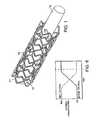
- FIG. 1is a perspective view of an embodiment of a stent.
- FIG. 2is a schematic, cross-sectional view of the stent of FIG. 1, taken along line 2 — 2 .
- FIG. 3is a schematic, cross-sectional view of a strut of an embodiment of a stent.
- FIG. 4is a schematic, partial cross-sectional view of a strut of an embodiment of a stent.
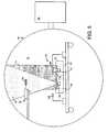
- FIG. 5is a schematic diagram of an embodiment of an ion beam assisted deposition system.
- FIG. 6is a plot of material concentration as a function of time.
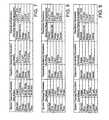
- FIG. 7is a table of parameters for an ion beam assisted deposition process.
- FIG. 8is a table of parameters for an ion beam assisted deposition process.
- FIG. 9is a table of parameters for an ion beam assisted deposition process.
- FIG. 1shows a support 12 carrying a stent 10 , which is in the form of a tubular member defined by struts 11 and openings 13 .
- support 12can be a balloon catheter or a catheter shaft.
- stent 10includes multiple cross-sectional portions.
- struts 11 of stent 10are formed of a relatively radiolucent core 14 surrounded by a relatively radiopaque portion 16 .
- Radiopaque portion 16includes a radiopaque layer 18 , e.g., made of gold, and a layer 20 , e.g., made of a gold-titanium alloy, that can enhance the biocompatibility of stent 10 .
- layer 20can be passivated to provide stent 10 with a relatively inert outer surface.
- stent 10can be formed by coating a relatively radiolucent stent with a radiopaque material, such as gold or platinum, to form layer 18 .
- a radiopaque materialsuch as gold or platinum
- Layer 20is then formed on the radiopaque material.
- Layer 20can be formed on the preformed radiopaque layer 18 and/or formed from a portion of the radiopaque layer.
- Layer 20is then passivated, e.g., by forming a layer of an oxide or nitride on layer 20 or by converting layer 20 to an oxide or a nitride.
- Core 14is generally formed of one or more core material selected to provide stent 10 with certain physical and mechanical properties.
- the core materialis selected to provide stent 10 with sufficient hoop strength and radial strength so the stent can maintain a body vessel open.
- Suitable core materialsinclude stainless steel (e.g., 316L stainless steel), Nitinol (e.g., for self-expandable stents), other titanium alloys, tantalum alloys, zirconium alloys, and/or niobium alloys.
- the mechanical mismatchcan cause, for example, inflammation and/or re-occlusion of the vessel.
- One method of reducing mechanical mismatchis to form the stent with less material (e.g., by forming smaller struts 11 ), thereby approximating the compliancy or resiliency of the vessel.
- reducing the amount of core material in stent 10can also reduce the radiopacity of the stent.
- the stentincludes radiopaque portion 16 disposed over core portion 14 .
- Portion 16includes radiopaque layer 18 , which is formed with a radiopaque material.
- the radiopaque materialcan be any material with a density and/or linear absorption coefficient sufficient to enhance the radiopacity of stent 10 .
- the radiopaque materialhas a density and/or linear absorption coefficient to attenuate an incident X-ray beam. In some cases, the radiopaque material has a density of equal to or greater than about 10 g/cc.
- Radiopaque materialsinclude gold, platinum, palladium, tantalum, iridium, cobalt, titanium, tungsten, stainless steel, Nitinol, and metal alloys containing a sufficient percentage of heavy elements.
- Radiopaque layer 18can be, for example, up to about 8 microns thick, e.g., about 6-8 microns, thick.
- Methods of forming radiopaque layer 18include, for example, electrodeposition, physical vapor deposition (e.g., sputtering), chemical vapor deposition, galvanizing, and/or dipping (e.g., in molten material).
- radiopaque portion 16includes a relatively inert layer 20 disposed over radiopaque layer 18 .
- Layer 20enhances the biocompatibility of stent 10 by providing the stent with a layer (as shown, an outer layer) that can be passivated, e.g., more easily than radiopaque layer 18 .
- layer 20is capable of reacting (e.g., oxidizing) and forming products, such as oxides, nitrides, and/or carbides, that are more inert, and therefore, more biocompatible, than the material(s) in radiopaque layer 18 .
- layer 20has a lower oxidation potential, i.e., can be more easily oxidized to form a biocompatible product.
- layer 20includes a mixture (here, an alloy) of the radiopaque material(s) in radiopaque layer 18 and one or more alloying material.
- the alloying materialcan be any material capable of forming a mixture with the radiopaque material(s), and forming a product that is more easily passivated than the radiopaque material(s).
- the alloying materialcan be, for example, tantalum, titanium, niobium, zirconium, chromium, silicon, rhodium, iridium, platinum, and/or palladium. Any of the alloying materials can be used with any of the radiopaque materials described above.
- the alloying materialcan be titanium.
- layer 20includes an alloy of gold-titanium, such as Au 0.30 Ti 0.70 , which can be more easily passivated than gold. That is, relative to gold, the gold-titanium alloy can more easily form or be converted to a product, e.g., an oxide, that is relatively inert and biocompatible.
- Au x Ti ygold-titanium
- xcan range from about 0-30%
- ycan range from about 70-100%.
- xcan be equal to or greater than about 0%, 5%, 10%, 15%, 20%, or 25%, and/or equal to or less than about 30%, 25%, 20%, 15%, 10%, or 5%.
- concentration of titanium, ycan be equal to or greater than about 70%, 75%, 80%, 85%, 90%, or 95%, and/or less than or equal to 100%, 95%, 90%, 85%, 80%, or 75%.
- Layer 20can be up to about 10 microns thick, e.g., about 0.1-10 microns thick. Ternary (e.g., Au—Ti—Cr) or higher mixtures or alloy systems can be formed.
- layer 20can be formed on a pre-formed radiopaque layer 18 .
- modified layer 20can be applied on the radiopaque layer by physical vapor deposition, including sputtering and ion beam assisted deposition, chemical vapor deposition, or electrodeposition.
- Layer 20can also be formed by forming layers, e.g., alternating layers, of the radiopaque material and the alloying material on layer 18 in a predetermined ratio, and heating the layers (e.g., at elevated, annealing temperatures) to form the alloy by diffusion.
- layer 20can be formed from a portion of a formed radiopaque layer 18 . That is, a portion of the radiopaque layer 18 can be converted to layer 20 .
- a gold-titanium layer 20can be formed by implanting titanium ions into a formed gold radiopaque layer 18 , and annealing the radiopaque layer. As a result, a certain thickness of the radiopaque layer (e.g., in the sub-micron range) is converted to an alloyed modified layer that can be passivated.
- a layer of alloy materiale.g., Ti
- radiopaque layer 18e.g., Au
- the layerscan be heated, e.g., annealed, to form an alloy, e.g., Au—Ti.
- FIG. 2shows radiopaque layer 18 and layer 20 as two discrete, well-defined layers
- the interface between the layersis not well defined.
- the endoprosthesiscan be formed with good adhesion and high durability (e.g., reduced risk of flaking). Corrosion from contact of dissimilar material can also be reduced.
- the interfacemay not be well defined, for example, when modified, layer 20 is formed from a formed radiopaque layer 18 .
- radiopaque portion 16does not include an interface between two layers.
- a strut 22 of a stentis formed of a relatively radiolucent core 24 surrounded by a relatively radiopaque layer 26 .
- Core 24is generally the same as core 14 described above.
- Radiopaque layer 26includes one or more radiopaque material and one or more alloying material, as described above.
- radiopaque layer 26is formed having a compositional gradient in which the concentration(s) of the alloying material(s) and/or the radiopaque material(s) varies along the thickness of layer 26 (arrows A and B).
- layer 26can be relatively gold-rich (or titanium-poor) at surface 28 adjacent to core 24 , and relatively gold-poor (or titanium-rich) at outer surface 30 .
- the concentration of the radiopaque materialcan be about 100%; and at outer surface 30 , the concentration of the alloying material can be about 100%.
- the concentration(s) of the radiopaque material(s) 1 and/or the alloying material(s)can vary linearly or non-linearly (e.g., exponentially) between surfaces 28 and 30 .
- the concentration(s), e.g., of the alloying materialcan increase or decrease from surface 28 to surface 30 .
- layer 26 having the compositional gradientcan be formed on a radiopaque layer, such as radiopaque layer 18 .
- compositionally-graded layer 26includes using physical vapor deposition while controlling the source of materials used for deposition.
- layer 26can be formed by forming alternating layers of a radiopaque material and an alloying material in a predetermined ratio, and annealing the layers.
- layers of titanium 27 a , 27 b , and 27 ccan be formed alternating with layers of gold 29 a , 29 b , and 29 c .
- Titanium layer 27 ais thicker than layer 27 b , which is thicker than layer 27 c .
- Gold layers 29 a - 29 care of equal thickness.
- stent 10can be passivated by exposing the stent to an appropriate environment.
- stent 10can be oxidized by heating the stent in an oxidizing atmosphere, such as one containing oxygen and/or water, to form an oxide layer on layer 20 or 26 .
- Nitridescan be formed by heating stent 10 in an atmosphere containing nitrogen, nitrogen-hydrogen, and/or ammonia.
- Carburizinge.g., increasing the surface concentration of carbon, can be performed by exposing stent 10 , at an elevated temperature, to an atmosphere rich in a hydrocarbon gas, such as methane.
- passivationcan be performed by electropolishing to produce an oxide-rich surface layer. In some cases, passivation can occur relatively spontaneously, e.g., upon exposure to air, when the oxidation potential is relatively low.
- Stent 10can then be finished, e.g., electropolished to a smooth finish, according to conventional methods. Stent 10 can be finished before passivation. Alternatively, stent 10 can be formed textured.
- Stent 10can then be used, e.g., delivered and expanded, according to conventional methods.
- stent 10can be self-expandable, balloon-expandable, or a combination of both.
- Examples of stent 10 and support 12are described in U.S. Pat. No. 5,725,570 (Heath) and U.S. Pat. No. 5,234,457 (Andersen), all hereby incorporated by reference.
- stent 10is a part of a stent-graft.
- the stent-graftcan be a stent attached to a biocompatible, non-porous or semi-porous polymer matrix made of polytetrafluoroethylene (PTFE), expanded PTFE, polyethylene, urethane, or polypropylene.
- Stent 10can include a releasable therapeutic agent or a pharmaceutically active compound, such as described in U.S. Pat. No. 5,674,242, and commonly-assigned U.S. Ser. No. 09/895,415, filed Jul. 2, 2001, all hereby incorporated by reference.
- the therapeutic agents or pharmaceutically active compoundscan include, for example, anti-thrombogenic agents, antioxidants, anti-inflammatory agents, anesthetic agents, anti-coagulants, and antibiotics.
- IBADion beam assisted deposition
- an IBAD system 50generally includes a fixture assembly 52 configured to support a stent 54 , and a deposition assembly 56 .
- System 50is used in a vacuum chamber 51 at pressures of about 1 ⁇ 10 ⁇ 4 ⁇ 3 ⁇ 10 ⁇ 4 Torr, provided in part by a diffusion pump 58 .
- Deposition assembly 56includes two crucibles 60 and 62 , their respective shutters 64 and 66 , two electron beam evaporators 68 and 70 , and an ion beam gun 72 .
- Crucibles 60 and 62e.g., made of graphite, contain materials to be deposited, such as gold and titanium.
- Electron beam evaporators 68 and 70are configured to generate a flow of electrons that can be focused (e.g., using magnetic fields) on the materials in crucibles 60 and 62 , respectively, to melt and to evaporate the materials to form thermally evaporated materials 76 .
- Evaporators 68 and 70can have water-cooled jackets that cool crucibles 60 and 62 , respectively.
- Ion beam gun 72is configured to receive a flow of argon (e.g., 2-4 sccm) and to ionize the argon to form a plasma 74 .
- Plasma 74is accelerated out of ion beam gun 72 to stent 54 using magnets (not shown).
- Shutters 64 and 66can be moved, e.g., swiveled, to allow or to block the flow of evaporated material 76 from crucibles 60 and 62 , respectively.
- Fixture assembly 52is generally configured to allow stent 54 to be uniformly coated with evaporated material 76 .
- the thermal evaporation processcan deposit a film of material 76 on a substrate that is in a line of sight of crucible 60 or 62 .
- the stentis rotated during deposition.
- stent 54is placed on a rotatable spindle. The friction between the stent and the spindle can hold the stent in place during rotation to provide a coated stent without contact points.
- stent 54can be clipped to a rotatable shaft.
- a quartz crystal 78is used to determine the thickness of the deposited material.
- Crystal 78is interfaced to a controller (not shown) and oscillated.
- the controlleris calibrated such that the thickness of material deposited on crystal 78 (and thus also stent 54 ) can be calculated by measuring the change in the oscillation frequency of the crystal.
- Stent 54e.g., a Nitinol or stainless steel stent, is thoroughly chemically cleaned.
- stent 54can be cleaned in a solvent (such as isopropyl alcohol or acetone) and a degreaser, and rinsed with deionized water.
- Heat and/or agitatione.g., using ultrasonic energy, can be used to clean stent 54 .
- Stent 54is then placed on fixture assembly 52 , which is then placed in vacuum chamber 51 , with the stent about two feet from crucibles 60 and 62 .
- Stent 54is then subjected to a sputter cleaning.
- Chamber 51is evacuated to a pressure of about 1 ⁇ 10 ⁇ 5 Torr, and ion beam gun 72 is activated.
- Ion beam gun 72ionizes argon gas to form plasma 74 , and the plasma is accelerated to stent 54 to sputter clean/etch the surface of the stent.
- the angle of incidence for plasma 74can be about 45-90°, e.g., about 70°.
- stent 54is sputter cleaned for about 20-30 minutes. An estimated 100-300 angstroms of material can be removed.
- a first materiale.g., gold in crucible 60
- a first materialis then deposited.
- electron beam evaporators 68 and 70are slowly ramped up.
- Shutters 64 and 66are over their respective crucibles 60 and 62 , so no material can deposit on stent 54 .
- shutter 64moves, e.g., swivels, to allow evaporated material to coat stent 54 .
- the surface of stent 54is simultaneously bombarded with plasma 74 .
- plasma 74transfers energy to the ions, freeing some ions from the surface of the stent and allowing some ions to migrate on the stent surface. As a result, it is believed that a composite including the first material is formed with enhanced density.
- a second materiale.g., titanium, tantalum, or platinum
- shutter 66is moved to allow the second material (in crucible 62 ) to co-deposit with the first material.
- concentrations of each materialcan be controlled by adjusting the power to evaporators 68 and 70 . For example, referring to FIG. 6, initially the concentration of the first material is relatively high, and the second material is then slowly introduced.
- shutter 64is moved to prevent the first material from depositing on stent 54 , and a pure layer of the second material is deposited over the alloy layer (i.e., the layer having the first and second materials). Then, stent 54 is allowed to cool, chamber 51 is returned to atmospheric pressure, and the stent is removed from the chamber.
- stent 54is then annealed.
- Annealingcan promote diffusion between the layers of materials and/or the layers and the stent substrate, and can strengthen bonding or adhesion between the layers.
- a Nitinol stentcan be annealed at about 300-400° C.
- a stainless steel stentcan be annealed at about 500-1000° C.
- Annealing timescan vary, e.g., from a few minutes to days, depending, for example, on the diffusion of the materials in stent 54 , which can be temperature-dependent.
- FIG. 7shows ranges for some process parameters.
- a stentwas coated with titanium using the procedures described above. The process parameters are shown in FIG. 8 .
- a stentwas coated with a platinum-gold using the procedures described above. The process parameters are shown in FIG. 9 .
- the platinum-gold gradientwas similar to that shown in FIG. 6 .
- one or more intermediate layerscan be formed between core 14 or 24 and radiopaque layer 18 or 26 , i.e., at least a portion of the core and the radiopaque layer do not contact.
- intermediate layer(s)can be selected to have intermediate lattice parameters to serve as buffer layer(s), thereby reducing (e.g., minimizing) stress between the core and the radiopaque layer.
- the intermediate layer(s)can be, for example, a mixture of the core material and the radiopaque material.
- Layer 20may not include the radiopaque material(s) in radiopaque layer 18 .
- a radiopaque layermay include gold, while layer 20 includes a material that can be passivated, such as a platinum-titanium alloy.
- Radiopaque layer 18 , layer 20 , and/or layer 26can cover all or only one or more selected portions of a stent.
- radiopaque layer 18 , layer 20 , and/or layer 26may be formed only on one or more end portions of the stent.
- a stentmay include a magnetopaque (i.e., visible by magnetic resonance imaging (MRI)) material on layer 20 or 26 .
- MRImagnetic resonance imaging
- Suitable magnetopaque materialsinclude, for example, non-ferrous metal-alloys containing paramagnetic elements (e.g., dysprosium or gadolinium) such as terbium-dysprosium, dysprosium, and gadolinium; non-ferrous metallic bands coated with an oxide or a carbide layer of dysprosium or gadolinium (e.g., Dy 2 O 3 or Gd 2 O 3 ); non-ferrous metals (e.g., copper, silver, platinum, or gold) coated with a layer of superparamagnetic material, such as nanocrystalline Fe 3 O 4 , CoFe 2 O 4 , MnFe 2 O 4 , or MgFe 2 O 4 ; and nanocrystalline particles of the transition metal oxides (e.g., oxides of Fe, Co, Ni).
- non-ferrous metal-alloys containing paramagnetic elementse.g., dysprosium or gadolinium
- radiopaque layer 18 , layer 20 , and/or layer 26may be formed on medical devices other than stents and stent-grafts, for example, those where radiopacity is desired such as orthopedic implants.
Landscapes
- Chemical & Material Sciences (AREA)
- Engineering & Computer Science (AREA)
- Chemical Kinetics & Catalysis (AREA)
- Materials Engineering (AREA)
- Metallurgy (AREA)
- Organic Chemistry (AREA)
- Mechanical Engineering (AREA)
- Health & Medical Sciences (AREA)
- Inorganic Chemistry (AREA)
- Public Health (AREA)
- Veterinary Medicine (AREA)
- Heart & Thoracic Surgery (AREA)
- Biomedical Technology (AREA)
- Vascular Medicine (AREA)
- Life Sciences & Earth Sciences (AREA)
- Animal Behavior & Ethology (AREA)
- General Health & Medical Sciences (AREA)
- Optics & Photonics (AREA)
- Physics & Mathematics (AREA)
- Epidemiology (AREA)
- Surgery (AREA)
- Cardiology (AREA)
- Oral & Maxillofacial Surgery (AREA)
- Transplantation (AREA)
- Electrochemistry (AREA)
- Materials For Medical Uses (AREA)
- Prostheses (AREA)
Abstract
Description
Claims (17)
Priority Applications (13)
| Application Number | Priority Date | Filing Date | Title |
|---|---|---|---|
| US10/263,212US6638301B1 (en) | 2002-10-02 | 2002-10-02 | Medical device with radiopacity |
| US10/629,934US7297157B2 (en) | 2002-10-02 | 2003-07-29 | Medical device with radiopacity |
| PCT/US2003/030682WO2004030578A2 (en) | 2002-10-02 | 2003-09-29 | Multilayer stent |
| CA 2500711CA2500711C (en) | 2002-10-02 | 2003-09-29 | Medical devices and methods of making the same |
| JP2004541837AJP2006501032A (en) | 2002-10-02 | 2003-09-29 | Multilayer stent |
| EP03754974AEP1549250B1 (en) | 2002-10-02 | 2003-09-29 | Medical devices and methods of making the same |
| AT03754974TATE392197T1 (en) | 2002-10-02 | 2003-09-29 | MEDICAL DEVICES AND PRODUCTION METHODS THEREOF |
| EP08154185AEP1938776A1 (en) | 2002-10-02 | 2003-09-29 | Medical devices and methods of making the same |
| AU2003272774AAU2003272774A1 (en) | 2002-10-02 | 2003-09-29 | Multilayer stent |
| DE2003620430DE60320430T2 (en) | 2002-10-02 | 2003-09-29 | MEDICAL DEVICES AND MANUFACTURING METHOD THEREFOR |
| US11/738,229US7682649B2 (en) | 2002-10-02 | 2007-04-20 | Medical devices and methods of making the same |
| US12/703,838US7967854B2 (en) | 2002-10-02 | 2010-02-11 | Medical devices and methods of making the same |
| US13/113,361US20110257730A1 (en) | 2002-10-02 | 2011-05-23 | Medical devices and methods of making the same |
Applications Claiming Priority (1)
| Application Number | Priority Date | Filing Date | Title |
|---|---|---|---|
| US10/263,212US6638301B1 (en) | 2002-10-02 | 2002-10-02 | Medical device with radiopacity |
Related Child Applications (1)
| Application Number | Title | Priority Date | Filing Date |
|---|---|---|---|
| US10/629,934ContinuationUS7297157B2 (en) | 2002-10-02 | 2003-07-29 | Medical device with radiopacity |
Publications (1)
| Publication Number | Publication Date |
|---|---|
| US6638301B1true US6638301B1 (en) | 2003-10-28 |
Family
ID=29250322
Family Applications (5)
| Application Number | Title | Priority Date | Filing Date |
|---|---|---|---|
| US10/263,212Expired - LifetimeUS6638301B1 (en) | 2002-10-02 | 2002-10-02 | Medical device with radiopacity |
| US10/629,934Expired - LifetimeUS7297157B2 (en) | 2002-10-02 | 2003-07-29 | Medical device with radiopacity |
| US11/738,229Expired - Fee RelatedUS7682649B2 (en) | 2002-10-02 | 2007-04-20 | Medical devices and methods of making the same |
| US12/703,838Expired - Fee RelatedUS7967854B2 (en) | 2002-10-02 | 2010-02-11 | Medical devices and methods of making the same |
| US13/113,361AbandonedUS20110257730A1 (en) | 2002-10-02 | 2011-05-23 | Medical devices and methods of making the same |
Family Applications After (4)
| Application Number | Title | Priority Date | Filing Date |
|---|---|---|---|
| US10/629,934Expired - LifetimeUS7297157B2 (en) | 2002-10-02 | 2003-07-29 | Medical device with radiopacity |
| US11/738,229Expired - Fee RelatedUS7682649B2 (en) | 2002-10-02 | 2007-04-20 | Medical devices and methods of making the same |
| US12/703,838Expired - Fee RelatedUS7967854B2 (en) | 2002-10-02 | 2010-02-11 | Medical devices and methods of making the same |
| US13/113,361AbandonedUS20110257730A1 (en) | 2002-10-02 | 2011-05-23 | Medical devices and methods of making the same |
Country Status (8)
| Country | Link |
|---|---|
| US (5) | US6638301B1 (en) |
| EP (2) | EP1549250B1 (en) |
| JP (1) | JP2006501032A (en) |
| AT (1) | ATE392197T1 (en) |
| AU (1) | AU2003272774A1 (en) |
| CA (1) | CA2500711C (en) |
| DE (1) | DE60320430T2 (en) |
| WO (1) | WO2004030578A2 (en) |
Cited By (59)
| Publication number | Priority date | Publication date | Assignee | Title |
|---|---|---|---|---|
| US20040049261A1 (en)* | 2002-09-09 | 2004-03-11 | Yixin Xu | Medical devices |
| US20040186377A1 (en)* | 2003-03-17 | 2004-09-23 | Sheng-Ping Zhong | Medical devices |
| US20050021129A1 (en)* | 2000-12-28 | 2005-01-27 | Pelton Brian Lee | Thermoelastic and superelastic Ni-Ti-W alloy |
| US20050075714A1 (en)* | 2003-09-24 | 2005-04-07 | Medtronic Vascular, Inc. | Gradient coated stent and method of fabrication |
| US20050165472A1 (en)* | 2004-01-22 | 2005-07-28 | Glocker David A. | Radiopaque coating for biomedical devices |
| US20050172471A1 (en)* | 2004-02-09 | 2005-08-11 | Vietmeier Kristopher H. | Process method for attaching radio opaque markers to shape memory stent |
| US20050187466A1 (en)* | 2004-01-22 | 2005-08-25 | Glocker David A. | Radiopaque coating for biomedical devices |
| WO2005084584A1 (en)* | 2004-03-02 | 2005-09-15 | Boston Scientific Scimed, Inc. | Medical devices including metallic films and methods for making same |
| US20050288773A1 (en)* | 2004-01-22 | 2005-12-29 | Glocker David A | Radiopaque coating for biomedical devices |
| US20060015026A1 (en)* | 2004-07-13 | 2006-01-19 | Glocker David A | Porous coatings on electrodes for biomedical implants |
| US20060129240A1 (en)* | 2004-12-10 | 2006-06-15 | Joe Lessar | Implants based on engineered composite materials having enhanced imaging and wear resistance |
| US20060178727A1 (en)* | 1998-12-03 | 2006-08-10 | Jacob Richter | Hybrid amorphous metal alloy stent |
| US20060200224A1 (en)* | 2005-03-03 | 2006-09-07 | Icon Interventional Systems, Inc. | Metal alloy for a stent |
| US20060198750A1 (en)* | 2005-03-03 | 2006-09-07 | Icon Medical Corp. | Process for forming an improved metal alloy stent |
| US20060235505A1 (en)* | 2005-03-14 | 2006-10-19 | Oepen Randolf V | Visible endoprosthesis |
| US20070077163A1 (en)* | 2005-03-03 | 2007-04-05 | Icon Medical Corp. | Process for forming an improved metal alloy stent |
| US20070106374A1 (en)* | 2004-01-22 | 2007-05-10 | Isoflux, Inc. | Radiopaque coating for biomedical devices |
| US20070213810A1 (en)* | 2005-03-14 | 2007-09-13 | Richard Newhauser | Segmented endoprosthesis |
| US20070250158A1 (en)* | 2006-04-25 | 2007-10-25 | Medtronic Vascular, Inc. | Laminated Implantable Medical Device Having a Metallic Coating |
| US20070255094A1 (en)* | 2005-03-14 | 2007-11-01 | Oepen Randolf V | Crack/fatigue resistant endoprosthesis |
| WO2005094486A3 (en)* | 2004-03-23 | 2007-11-29 | Isoflux Inc | Radiopaque coating for biomedical devices |
| US20080058919A1 (en)* | 2006-08-01 | 2008-03-06 | Kramer-Brown Pamela A | Composite polymeric and metallic stent with radiopacity |
| US20080177371A1 (en)* | 2006-08-28 | 2008-07-24 | Cornova, Inc. | Implantable devices and methods of forming the same |
| US20080195194A1 (en)* | 2007-02-13 | 2008-08-14 | Abbott Cardiovascular Systems Inc. | Mri compatible, radiopaque alloys for use in medical devices |
| US20080206441A1 (en)* | 2007-02-27 | 2008-08-28 | Medtronic Vascular, Inc. | Ion Beam Etching a Surface of an Implantable Medical Device |
| WO2008106307A1 (en)* | 2007-02-27 | 2008-09-04 | Medtronic Vascular Inc. | High temperature oxidation-reduction process to form porous structures on a medical implant |
| WO2008141336A1 (en)* | 2007-05-15 | 2008-11-20 | Abbott Laboratories | Radiopaque markers and medical devices comprising binary alloys of titanium |
| US20090099645A1 (en)* | 2007-05-15 | 2009-04-16 | Abbott Laboratories | Radiopaque markers and medical devices comprising binary alloys of titanium |
| US20090112306A1 (en)* | 2007-10-24 | 2009-04-30 | Craig Bonsignore | Stent segments axially connected by thin film |
| US20100010622A1 (en)* | 2006-03-13 | 2010-01-14 | Abbott Laboratories | Hybrid segmented endoprosthesis |
| EP2169092A2 (en)* | 2004-12-16 | 2010-03-31 | AGC Flat Glass Europe SA | Substrate with antimicrobial properties |
| US20100174360A1 (en)* | 2002-10-02 | 2010-07-08 | Boston Scientific Scimed, Inc. | Medical Devices and Methods of Making the Same |
| US20100305682A1 (en)* | 2006-09-21 | 2010-12-02 | Cleveny Technologies | Specially configured and surface modified medical device with certain design features that utilize the intrinsic properties of tungsten, zirconium, tantalum and/or niobium |
| US7854760B2 (en) | 2005-05-16 | 2010-12-21 | Boston Scientific Scimed, Inc. | Medical devices including metallic films |
| US7901447B2 (en) | 2004-12-29 | 2011-03-08 | Boston Scientific Scimed, Inc. | Medical devices including a metallic film and at least one filament |
| US20110214785A1 (en)* | 2010-03-04 | 2011-09-08 | Icon Medical Corp. | method for forming a tubular medical device |
| JP2011184803A (en)* | 2004-06-14 | 2011-09-22 | Isoflux Inc | Radiopaque coating for biomedical device |
| US20120209373A1 (en)* | 2009-04-18 | 2012-08-16 | Martina Schmitt | Coated Stint |
| WO2012125676A1 (en)* | 2011-03-15 | 2012-09-20 | Boston Scientific Scimed, Inc. | Implantable medical devices incorporating x-ray mirrors |
| US8591568B2 (en) | 2004-03-02 | 2013-11-26 | Boston Scientific Scimed, Inc. | Medical devices including metallic films and methods for making same |
| WO2014003847A1 (en)* | 2012-06-26 | 2014-01-03 | Abbott Cardiovascular Systems Inc. | Implantable prosthesis with hollow struts and passivating coating, and method of making same |
| US8632580B2 (en) | 2004-12-29 | 2014-01-21 | Boston Scientific Scimed, Inc. | Flexible medical devices including metallic films |
| WO2014169261A1 (en) | 2013-04-11 | 2014-10-16 | Blockade Medical, LLC | Radiopaque devices for cerebral aneurysm repair |
| EP2796112A1 (en)* | 2005-04-05 | 2014-10-29 | Elixir Medical Corporation | Degradable implantable medical devices |
| US8894824B2 (en) | 2004-06-28 | 2014-11-25 | Isoflux, Inc. | Porous coatings for biomedical implants |
| US8992592B2 (en)* | 2004-12-29 | 2015-03-31 | Boston Scientific Scimed, Inc. | Medical devices including metallic films |
| US8998973B2 (en) | 2004-03-02 | 2015-04-07 | Boston Scientific Scimed, Inc. | Medical devices including metallic films |
| US9039755B2 (en) | 2003-06-27 | 2015-05-26 | Medinol Ltd. | Helical hybrid stent |
| US9107899B2 (en) | 2005-03-03 | 2015-08-18 | Icon Medical Corporation | Metal alloys for medical devices |
| US9149375B2 (en) | 2012-06-26 | 2015-10-06 | Abbott Cardiovascular Systems Inc. | Radiopaque drug-filled prosthesis and method of making same |
| US9155639B2 (en) | 2009-04-22 | 2015-10-13 | Medinol Ltd. | Helical hybrid stent |
| US9155645B2 (en) | 2012-06-26 | 2015-10-13 | Abbott Cardiovascular Systems Inc. | Implantable prosthesis with radiopaque particles and method of making same |
| US20150305826A1 (en)* | 2014-04-29 | 2015-10-29 | Stryker Corporation | Method for producing radiopaque medical implants |
| US9456910B2 (en) | 2003-06-27 | 2016-10-04 | Medinol Ltd. | Helical hybrid stent |
| US9956320B2 (en) | 2003-06-27 | 2018-05-01 | Zuli Holdings Ltd. | Amorphous metal alloy medical devices |
| DE102018218130A1 (en) | 2018-10-23 | 2020-04-23 | Karlsruher Institut für Technologie | Stent for implantation in a cavity of a human or animal body and method for producing an X-ray-opaque layer structure on a stent |
| CN112370224A (en)* | 2015-02-11 | 2021-02-19 | 雅培心血管系统公司 | Stent structure with radiopaque markers |
| US11766506B2 (en) | 2016-03-04 | 2023-09-26 | Mirus Llc | Stent device for spinal fusion |
| US11779685B2 (en) | 2014-06-24 | 2023-10-10 | Mirus Llc | Metal alloys for medical devices |
Families Citing this family (25)
| Publication number | Priority date | Publication date | Assignee | Title |
|---|---|---|---|---|
| JP4612186B2 (en)* | 1998-02-24 | 2011-01-12 | ナビリスト メディカル, インコーポレイテッド | High flow dialysis catheter and related methods |
| US20050065437A1 (en)* | 2003-09-24 | 2005-03-24 | Scimed Life Systems, Inc. | Medical device with markers for magnetic resonance visibility |
| ES2693248T3 (en) | 2004-12-24 | 2018-12-10 | Hexacath | Mechanical part with improved deformability |
| US20070135751A1 (en)* | 2005-12-09 | 2007-06-14 | Dicarlo Paul D | Medical devices |
| US20070131317A1 (en)* | 2005-12-12 | 2007-06-14 | Accellent | Nickel-titanium alloy with a non-alloyed dispersion and methods of making same |
| US20070173925A1 (en)* | 2006-01-25 | 2007-07-26 | Cornova, Inc. | Flexible expandable stent |
| US20080051759A1 (en)* | 2006-08-24 | 2008-02-28 | Boston Scientific Scimed, Inc. | Polycarbonate polyurethane venous access devices |
| WO2008027871A2 (en)* | 2006-08-28 | 2008-03-06 | Cornova, Inc. | Implantable devices and methods of forming the same |
| WO2008089537A1 (en)* | 2007-01-22 | 2008-07-31 | Baylis Medical Company Inc. | Positioning tool for positioning an instrument at a treatment site |
| DE102007030751B4 (en)* | 2007-07-02 | 2009-06-10 | Acandis Gmbh & Co. Kg | Method of making a stent |
| WO2009052506A1 (en)* | 2007-10-19 | 2009-04-23 | Navilyst Medical, Inc. | Recirculation minimizing catheter |
| US20100256546A1 (en)* | 2009-04-03 | 2010-10-07 | Davis Scott A | Polycarbonate Polyurethane Venous Access Devices Having Enhanced Strength |
| US20110071500A1 (en)* | 2009-09-21 | 2011-03-24 | Navilyst Medical, Inc. | Branched catheter tip |
| US8512483B2 (en) | 2009-09-28 | 2013-08-20 | Biotronik Vi Patent Ag | Implant and method for manufacturing same |
| EP2338534A2 (en)* | 2009-12-21 | 2011-06-29 | Biotronik VI Patent AG | Medical implant, coating method and implantation method |
| US8328760B2 (en)* | 2010-01-11 | 2012-12-11 | Angiodynamics, Inc. | Occlusion resistant catheter |
| WO2011140394A1 (en) | 2010-05-05 | 2011-11-10 | Medical Components, Inc. | Method and apparatus for printing radiopaque indicia |
| US9144268B2 (en) | 2010-11-02 | 2015-09-29 | Nike, Inc. | Strand-wound bladder |
| US9999746B2 (en) | 2011-03-22 | 2018-06-19 | Angiodynamics, Inc. | High flow catheters |
| US9050435B2 (en) | 2011-03-22 | 2015-06-09 | Angiodynamics, Inc. | High flow catheters |
| US9707339B2 (en) | 2012-03-28 | 2017-07-18 | Angiodynamics, Inc. | High flow rate dual reservoir port system |
| US9713704B2 (en) | 2012-03-29 | 2017-07-25 | Bradley D. Chartrand | Port reservoir cleaning system and method |
| CN104207866B (en)* | 2013-05-30 | 2016-12-07 | 深圳市先健生物材料技术有限公司 | The medical apparatus and instruments of biological absorbable or the manufacture method of its absorbable parts |
| US10166321B2 (en) | 2014-01-09 | 2019-01-01 | Angiodynamics, Inc. | High-flow port and infusion needle systems |
| EP3295969A1 (en)* | 2016-09-20 | 2018-03-21 | Cook Medical Technologies LLC | Radiopaque composite wire for medical applications and method of making a radiopaque composite wire |
Citations (13)
| Publication number | Priority date | Publication date | Assignee | Title |
|---|---|---|---|---|
| US5234457A (en) | 1991-10-09 | 1993-08-10 | Boston Scientific Corporation | Impregnated stent |
| US5593438A (en)* | 1995-01-20 | 1997-01-14 | Akhavi; David S. | Intraocular lens with metallic coatings for preventing secondary cataracts |
| US5630840A (en) | 1993-01-19 | 1997-05-20 | Schneider (Usa) Inc | Clad composite stent |
| US5674242A (en) | 1995-06-06 | 1997-10-07 | Quanam Medical Corporation | Endoprosthetic device with therapeutic compound |
| US5725570A (en) | 1992-03-31 | 1998-03-10 | Boston Scientific Corporation | Tubular medical endoprostheses |
| US5858556A (en) | 1997-01-21 | 1999-01-12 | Uti Corporation | Multilayer composite tubular structure and method of making |
| US6099561A (en)* | 1996-10-21 | 2000-08-08 | Inflow Dynamics, Inc. | Vascular and endoluminal stents with improved coatings |
| US6174329B1 (en) | 1996-08-22 | 2001-01-16 | Advanced Cardiovascular Systems, Inc. | Protective coating for a stent with intermediate radiopaque coating |
| US6248190B1 (en) | 1998-06-15 | 2001-06-19 | Scimed Life Systems, Inc. | Process of making composite stents with gold alloy cores |
| US6315794B1 (en) | 1997-11-13 | 2001-11-13 | Medinol Ltd. | Multilayered metal stent |
| US6334871B1 (en) | 1996-03-13 | 2002-01-01 | Medtronic, Inc. | Radiopaque stent markers |
| US20020058989A1 (en) | 2000-09-22 | 2002-05-16 | Chao Chen | Stent with optimal strength and radiopacity characteristics |
| US6471721B1 (en)* | 1999-12-30 | 2002-10-29 | Advanced Cardiovascular Systems, Inc. | Vascular stent having increased radiopacity and method for making same |
Family Cites Families (36)
| Publication number | Priority date | Publication date | Assignee | Title |
|---|---|---|---|---|
| US5643740A (en)* | 1983-02-24 | 1997-07-01 | Ronald J. Billing | Monoclonal antibody specific for activated lymphocytes and monocytes |
| US5015183A (en)* | 1989-08-07 | 1991-05-14 | Fenick Thomas J | Locating device and method of placing a tooth implant |
| US5222971A (en)* | 1990-10-09 | 1993-06-29 | Scimed Life Systems, Inc. | Temporary stent and methods for use and manufacture |
| WO1993007924A1 (en)* | 1991-10-18 | 1993-04-29 | Spire Corporation | Bactericidal coatings for implants |
| US5522904A (en)* | 1993-10-13 | 1996-06-04 | Hercules Incorporated | Composite femoral implant having increased neck strength |
| US5728079A (en)* | 1994-09-19 | 1998-03-17 | Cordis Corporation | Catheter which is visible under MRI |
| CA2178541C (en) | 1995-06-07 | 2009-11-24 | Neal E. Fearnot | Implantable medical device |
| US6261320B1 (en)* | 1996-11-21 | 2001-07-17 | Radiance Medical Systems, Inc. | Radioactive vascular liner |
| US6287249B1 (en)* | 1998-02-19 | 2001-09-11 | Radiance Medical Systems, Inc. | Thin film radiation source |
| IL133212A (en)* | 1997-06-02 | 2005-12-18 | Janssen Pharmaceutica Nv | Use of (imidazol-5-yl) methyl-2-quinolinone derivatives to inhibit smooth muscle cell proliferation |
| US5919126A (en) | 1997-07-07 | 1999-07-06 | Implant Sciences Corporation | Coronary stent with a radioactive, radiopaque coating |
| US6309420B1 (en)* | 1997-10-14 | 2001-10-30 | Parallax Medical, Inc. | Enhanced visibility materials for implantation in hard tissue |
| US6503271B2 (en)* | 1998-01-09 | 2003-01-07 | Cordis Corporation | Intravascular device with improved radiopacity |
| US7713297B2 (en)* | 1998-04-11 | 2010-05-11 | Boston Scientific Scimed, Inc. | Drug-releasing stent with ceramic-containing layer |
| DE19916086B4 (en)* | 1998-04-11 | 2004-11-11 | Inflow Dynamics Inc. | Implantable prosthesis, especially vascular prosthesis (stent) |
| US6361759B1 (en)* | 1998-05-26 | 2002-03-26 | Wisconsin Alumni Research Foundation | MR signal-emitting coatings |
| US6299980B1 (en)* | 1998-09-29 | 2001-10-09 | Medtronic Ave, Inc. | One step lubricious coating |
| US6475644B1 (en)* | 1998-11-18 | 2002-11-05 | Radiovascular Systems, L.L.C. | Radioactive coating solutions methods, and substrates |
| US6342055B1 (en)* | 1999-04-29 | 2002-01-29 | Theken Surgical Llc | Bone fixation system |
| US6387123B1 (en)* | 1999-10-13 | 2002-05-14 | Advanced Cardiovascular Systems, Inc. | Stent with radiopaque core |
| US7335426B2 (en)* | 1999-11-19 | 2008-02-26 | Advanced Bio Prosthetic Surfaces, Ltd. | High strength vacuum deposited nitinol alloy films and method of making same |
| JP2004503334A (en) | 2000-07-14 | 2004-02-05 | アドバンスド、カーディオバスキュラー、システムズ、インコーポレーテッド | Radiopaque stent made of binary alloy |
| US7402173B2 (en)* | 2000-09-18 | 2008-07-22 | Boston Scientific Scimed, Inc. | Metal stent with surface layer of noble metal oxide and method of fabrication |
| US7077837B2 (en) | 2000-11-20 | 2006-07-18 | Implant Sciences Corporation | Multi-layered radiopaque coating on intravascular devices |
| US6569194B1 (en)* | 2000-12-28 | 2003-05-27 | Advanced Cardiovascular Systems, Inc. | Thermoelastic and superelastic Ni-Ti-W alloy |
| US6548013B2 (en)* | 2001-01-24 | 2003-04-15 | Scimed Life Systems, Inc. | Processing of particulate Ni-Ti alloy to achieve desired shape and properties |
| US20020138136A1 (en)* | 2001-03-23 | 2002-09-26 | Scimed Life Systems, Inc. | Medical device having radio-opacification and barrier layers |
| US6676987B2 (en) | 2001-07-02 | 2004-01-13 | Scimed Life Systems, Inc. | Coating a medical appliance with a bubble jet printing head |
| US6926733B2 (en)* | 2001-08-02 | 2005-08-09 | Boston Scientific Scimed, Inc. | Method for enhancing sheet or tubing metal stent radiopacity |
| US6908480B2 (en)* | 2001-08-29 | 2005-06-21 | Swaminathan Jayaraman | Structurally variable stents |
| US6866669B2 (en)* | 2001-10-12 | 2005-03-15 | Cordis Corporation | Locking handle deployment mechanism for medical device and method |
| US20040015229A1 (en)* | 2002-07-22 | 2004-01-22 | Syntheon, Llc | Vascular stent with radiopaque markers |
| US20040054399A1 (en)* | 2002-09-17 | 2004-03-18 | Roth Noah M. | Anti-galvanic stent coating |
| US6712852B1 (en)* | 2002-09-30 | 2004-03-30 | Depuy Spine, Inc. | Laminoplasty cage |
| US6638301B1 (en) | 2002-10-02 | 2003-10-28 | Scimed Life Systems, Inc. | Medical device with radiopacity |
| US7727273B2 (en)* | 2005-01-13 | 2010-06-01 | Boston Scientific Scimed, Inc. | Medical devices and methods of making the same |
- 2002
- 2002-10-02USUS10/263,212patent/US6638301B1/ennot_activeExpired - Lifetime
- 2003
- 2003-07-29USUS10/629,934patent/US7297157B2/ennot_activeExpired - Lifetime
- 2003-09-29JPJP2004541837Apatent/JP2006501032A/enactivePending
- 2003-09-29EPEP03754974Apatent/EP1549250B1/ennot_activeExpired - Lifetime
- 2003-09-29EPEP08154185Apatent/EP1938776A1/ennot_activeWithdrawn
- 2003-09-29CACA 2500711patent/CA2500711C/ennot_activeExpired - Fee Related
- 2003-09-29DEDE2003620430patent/DE60320430T2/ennot_activeExpired - Lifetime
- 2003-09-29WOPCT/US2003/030682patent/WO2004030578A2/enactiveApplication Filing
- 2003-09-29ATAT03754974Tpatent/ATE392197T1/ennot_activeIP Right Cessation
- 2003-09-29AUAU2003272774Apatent/AU2003272774A1/ennot_activeAbandoned
- 2007
- 2007-04-20USUS11/738,229patent/US7682649B2/ennot_activeExpired - Fee Related
- 2010
- 2010-02-11USUS12/703,838patent/US7967854B2/ennot_activeExpired - Fee Related
- 2011
- 2011-05-23USUS13/113,361patent/US20110257730A1/ennot_activeAbandoned
Patent Citations (13)
| Publication number | Priority date | Publication date | Assignee | Title |
|---|---|---|---|---|
| US5234457A (en) | 1991-10-09 | 1993-08-10 | Boston Scientific Corporation | Impregnated stent |
| US5725570A (en) | 1992-03-31 | 1998-03-10 | Boston Scientific Corporation | Tubular medical endoprostheses |
| US5630840A (en) | 1993-01-19 | 1997-05-20 | Schneider (Usa) Inc | Clad composite stent |
| US5593438A (en)* | 1995-01-20 | 1997-01-14 | Akhavi; David S. | Intraocular lens with metallic coatings for preventing secondary cataracts |
| US5674242A (en) | 1995-06-06 | 1997-10-07 | Quanam Medical Corporation | Endoprosthetic device with therapeutic compound |
| US6334871B1 (en) | 1996-03-13 | 2002-01-01 | Medtronic, Inc. | Radiopaque stent markers |
| US6174329B1 (en) | 1996-08-22 | 2001-01-16 | Advanced Cardiovascular Systems, Inc. | Protective coating for a stent with intermediate radiopaque coating |
| US6099561A (en)* | 1996-10-21 | 2000-08-08 | Inflow Dynamics, Inc. | Vascular and endoluminal stents with improved coatings |
| US5858556A (en) | 1997-01-21 | 1999-01-12 | Uti Corporation | Multilayer composite tubular structure and method of making |
| US6315794B1 (en) | 1997-11-13 | 2001-11-13 | Medinol Ltd. | Multilayered metal stent |
| US6248190B1 (en) | 1998-06-15 | 2001-06-19 | Scimed Life Systems, Inc. | Process of making composite stents with gold alloy cores |
| US6471721B1 (en)* | 1999-12-30 | 2002-10-29 | Advanced Cardiovascular Systems, Inc. | Vascular stent having increased radiopacity and method for making same |
| US20020058989A1 (en) | 2000-09-22 | 2002-05-16 | Chao Chen | Stent with optimal strength and radiopacity characteristics |
Non-Patent Citations (1)
| Title |
|---|
| Henderson et al., U.S.S.N. 09/898,103, "ePTFE Graft with Axial Elongation Properties", filed Jul. 3, 2001. |
Cited By (110)
| Publication number | Priority date | Publication date | Assignee | Title |
|---|---|---|---|---|
| US20060178727A1 (en)* | 1998-12-03 | 2006-08-10 | Jacob Richter | Hybrid amorphous metal alloy stent |
| US20050021129A1 (en)* | 2000-12-28 | 2005-01-27 | Pelton Brian Lee | Thermoelastic and superelastic Ni-Ti-W alloy |
| US8382819B2 (en) | 2000-12-28 | 2013-02-26 | Abbot Cardiovascular Systems Inc. | Thermoelastic and superelastic Ni-Ti-W alloy |
| US8702790B2 (en) | 2000-12-28 | 2014-04-22 | Abbott Cardiovascular Systems Inc. | Thermoelastic and superelastic Ni—Ti—W alloy |
| US7658760B2 (en) | 2000-12-28 | 2010-02-09 | Abbott Cardiovascular Systems Inc. | Thermoelastic and superelastic Ni-Ti-W alloy |
| US8974517B2 (en) | 2000-12-28 | 2015-03-10 | Abbott Cardiovascular Systems Inc. | Thermoelastic and superelastic NI-TI-W alloy |
| US20040049261A1 (en)* | 2002-09-09 | 2004-03-11 | Yixin Xu | Medical devices |
| US20100217376A1 (en)* | 2002-09-09 | 2010-08-26 | Yixin Xu | Medical devices |
| US20100174360A1 (en)* | 2002-10-02 | 2010-07-08 | Boston Scientific Scimed, Inc. | Medical Devices and Methods of Making the Same |
| US7967854B2 (en)* | 2002-10-02 | 2011-06-28 | Boston Scientific Scimed, Inc. | Medical devices and methods of making the same |
| US7792568B2 (en)* | 2003-03-17 | 2010-09-07 | Boston Scientific Scimed, Inc. | MRI-visible medical devices |
| US20040186377A1 (en)* | 2003-03-17 | 2004-09-23 | Sheng-Ping Zhong | Medical devices |
| US9603731B2 (en) | 2003-06-27 | 2017-03-28 | Medinol Ltd. | Helical hybrid stent |
| US9956320B2 (en) | 2003-06-27 | 2018-05-01 | Zuli Holdings Ltd. | Amorphous metal alloy medical devices |
| US9456910B2 (en) | 2003-06-27 | 2016-10-04 | Medinol Ltd. | Helical hybrid stent |
| US9039755B2 (en) | 2003-06-27 | 2015-05-26 | Medinol Ltd. | Helical hybrid stent |
| US10363152B2 (en) | 2003-06-27 | 2019-07-30 | Medinol Ltd. | Helical hybrid stent |
| US8801692B2 (en)* | 2003-09-24 | 2014-08-12 | Medtronic Vascular, Inc. | Gradient coated stent and method of fabrication |
| US20050075714A1 (en)* | 2003-09-24 | 2005-04-07 | Medtronic Vascular, Inc. | Gradient coated stent and method of fabrication |
| US20050288773A1 (en)* | 2004-01-22 | 2005-12-29 | Glocker David A | Radiopaque coating for biomedical devices |
| US20050187466A1 (en)* | 2004-01-22 | 2005-08-25 | Glocker David A. | Radiopaque coating for biomedical devices |
| US8002822B2 (en)* | 2004-01-22 | 2011-08-23 | Isoflux, Inc. | Radiopaque coating for biomedical devices |
| US20070106374A1 (en)* | 2004-01-22 | 2007-05-10 | Isoflux, Inc. | Radiopaque coating for biomedical devices |
| EP1706068A4 (en)* | 2004-01-22 | 2008-10-15 | Isoflux Inc | Radiopaque coating for biomedical devices |
| US20050165472A1 (en)* | 2004-01-22 | 2005-07-28 | Glocker David A. | Radiopaque coating for biomedical devices |
| US7243408B2 (en) | 2004-02-09 | 2007-07-17 | Boston Scientific Scimed, Inc. | Process method for attaching radio opaque markers to shape memory stent |
| US20050172471A1 (en)* | 2004-02-09 | 2005-08-11 | Vietmeier Kristopher H. | Process method for attaching radio opaque markers to shape memory stent |
| US8591568B2 (en) | 2004-03-02 | 2013-11-26 | Boston Scientific Scimed, Inc. | Medical devices including metallic films and methods for making same |
| US8998973B2 (en) | 2004-03-02 | 2015-04-07 | Boston Scientific Scimed, Inc. | Medical devices including metallic films |
| WO2005084584A1 (en)* | 2004-03-02 | 2005-09-15 | Boston Scientific Scimed, Inc. | Medical devices including metallic films and methods for making same |
| JP2008502373A (en)* | 2004-03-23 | 2008-01-31 | イソフラックス・インコーポレイテッド | Radiopaque coatings for biomedical devices |
| WO2005094486A3 (en)* | 2004-03-23 | 2007-11-29 | Isoflux Inc | Radiopaque coating for biomedical devices |
| JP2011184803A (en)* | 2004-06-14 | 2011-09-22 | Isoflux Inc | Radiopaque coating for biomedical device |
| EP1755490A4 (en)* | 2004-06-14 | 2011-08-17 | Isoflux Inc | Radiopaque coating for biomedical devices |
| US8894824B2 (en) | 2004-06-28 | 2014-11-25 | Isoflux, Inc. | Porous coatings for biomedical implants |
| US20060015026A1 (en)* | 2004-07-13 | 2006-01-19 | Glocker David A | Porous coatings on electrodes for biomedical implants |
| US20060129240A1 (en)* | 2004-12-10 | 2006-06-15 | Joe Lessar | Implants based on engineered composite materials having enhanced imaging and wear resistance |
| EP2169092A2 (en)* | 2004-12-16 | 2010-03-31 | AGC Flat Glass Europe SA | Substrate with antimicrobial properties |
| US8864815B2 (en) | 2004-12-29 | 2014-10-21 | Boston Scientific Scimed, Inc. | Medical devices including metallic film and at least one filament |
| US8632580B2 (en) | 2004-12-29 | 2014-01-21 | Boston Scientific Scimed, Inc. | Flexible medical devices including metallic films |
| US7901447B2 (en) | 2004-12-29 | 2011-03-08 | Boston Scientific Scimed, Inc. | Medical devices including a metallic film and at least one filament |
| US8992592B2 (en)* | 2004-12-29 | 2015-03-31 | Boston Scientific Scimed, Inc. | Medical devices including metallic films |
| US20060198750A1 (en)* | 2005-03-03 | 2006-09-07 | Icon Medical Corp. | Process for forming an improved metal alloy stent |
| US20090200177A1 (en)* | 2005-03-03 | 2009-08-13 | Icon Medical Corp. | Process for forming an improved metal alloy stent |
| US7540994B2 (en) | 2005-03-03 | 2009-06-02 | Icon Medical Corp. | Process for forming an improved metal alloy stent |
| US7648590B2 (en) | 2005-03-03 | 2010-01-19 | ICON International Systems, Inc. | Metal alloy for a stent |
| US7648591B2 (en) | 2005-03-03 | 2010-01-19 | Icon Medical Corp. | Metal alloys for medical devices |
| US7648592B2 (en) | 2005-03-03 | 2010-01-19 | Icon Medical Corp. | Metal alloy for a stent |
| US7540995B2 (en) | 2005-03-03 | 2009-06-02 | Icon Medical Corp. | Process for forming an improved metal alloy stent |
| US20090123327A1 (en)* | 2005-03-03 | 2009-05-14 | Furst Joseph G | Metal alloy for a stent |
| US20090076589A1 (en)* | 2005-03-03 | 2009-03-19 | Icon Interventional Systems, Inc. | Metal alloy for a stent |
| US7488444B2 (en) | 2005-03-03 | 2009-02-10 | Icon Medical Corp. | Metal alloys for medical devices |
| US7452502B2 (en) | 2005-03-03 | 2008-11-18 | Icon Medical Corp. | Metal alloy for a stent |
| US7452501B2 (en) | 2005-03-03 | 2008-11-18 | Icon Medical Corp. | Metal alloy for a stent |
| US8808618B2 (en) | 2005-03-03 | 2014-08-19 | Icon Medical Corp. | Process for forming an improved metal alloy stent |
| US9107899B2 (en) | 2005-03-03 | 2015-08-18 | Icon Medical Corporation | Metal alloys for medical devices |
| US20070077163A1 (en)* | 2005-03-03 | 2007-04-05 | Icon Medical Corp. | Process for forming an improved metal alloy stent |
| US20060200225A1 (en)* | 2005-03-03 | 2006-09-07 | Icon Interventional Systems, Inc. | Metal alloy for a stent |
| US20060200224A1 (en)* | 2005-03-03 | 2006-09-07 | Icon Interventional Systems, Inc. | Metal alloy for a stent |
| US20070213810A1 (en)* | 2005-03-14 | 2007-09-13 | Richard Newhauser | Segmented endoprosthesis |
| US20060235505A1 (en)* | 2005-03-14 | 2006-10-19 | Oepen Randolf V | Visible endoprosthesis |
| US7837726B2 (en)* | 2005-03-14 | 2010-11-23 | Abbott Laboratories | Visible endoprosthesis |
| US20070255094A1 (en)* | 2005-03-14 | 2007-11-01 | Oepen Randolf V | Crack/fatigue resistant endoprosthesis |
| EP2796112A1 (en)* | 2005-04-05 | 2014-10-29 | Elixir Medical Corporation | Degradable implantable medical devices |
| US10350093B2 (en) | 2005-04-05 | 2019-07-16 | Elixir Medical Corporation | Degradable implantable medical devices |
| US7854760B2 (en) | 2005-05-16 | 2010-12-21 | Boston Scientific Scimed, Inc. | Medical devices including metallic films |
| US8152841B2 (en) | 2005-05-16 | 2012-04-10 | Boston Scientific Scimed, Inc. | Medical devices including metallic films |
| US20100010622A1 (en)* | 2006-03-13 | 2010-01-14 | Abbott Laboratories | Hybrid segmented endoprosthesis |
| US7955383B2 (en)* | 2006-04-25 | 2011-06-07 | Medtronics Vascular, Inc. | Laminated implantable medical device having a metallic coating |
| US20070250158A1 (en)* | 2006-04-25 | 2007-10-25 | Medtronic Vascular, Inc. | Laminated Implantable Medical Device Having a Metallic Coating |
| US9265866B2 (en) | 2006-08-01 | 2016-02-23 | Abbott Cardiovascular Systems Inc. | Composite polymeric and metallic stent with radiopacity |
| US20080058919A1 (en)* | 2006-08-01 | 2008-03-06 | Kramer-Brown Pamela A | Composite polymeric and metallic stent with radiopacity |
| US20080177371A1 (en)* | 2006-08-28 | 2008-07-24 | Cornova, Inc. | Implantable devices and methods of forming the same |
| US20080215132A1 (en)* | 2006-08-28 | 2008-09-04 | Cornova, Inc. | Implantable devices having textured surfaces and methods of forming the same |
| US20100305682A1 (en)* | 2006-09-21 | 2010-12-02 | Cleveny Technologies | Specially configured and surface modified medical device with certain design features that utilize the intrinsic properties of tungsten, zirconium, tantalum and/or niobium |
| US8769794B2 (en)* | 2006-09-21 | 2014-07-08 | Mico Innovations, Llc | Specially configured and surface modified medical device with certain design features that utilize the intrinsic properties of tungsten, zirconium, tantalum and/or niobium |
| US20080195194A1 (en)* | 2007-02-13 | 2008-08-14 | Abbott Cardiovascular Systems Inc. | Mri compatible, radiopaque alloys for use in medical devices |
| WO2008100852A3 (en)* | 2007-02-13 | 2009-12-03 | Abbott Cardiovascular Systems Inc. | Mri compatible, radiopaque alloys for use in medical devices |
| US20080206441A1 (en)* | 2007-02-27 | 2008-08-28 | Medtronic Vascular, Inc. | Ion Beam Etching a Surface of an Implantable Medical Device |
| WO2008106307A1 (en)* | 2007-02-27 | 2008-09-04 | Medtronic Vascular Inc. | High temperature oxidation-reduction process to form porous structures on a medical implant |
| US20090099645A1 (en)* | 2007-05-15 | 2009-04-16 | Abbott Laboratories | Radiopaque markers and medical devices comprising binary alloys of titanium |
| US8500786B2 (en) | 2007-05-15 | 2013-08-06 | Abbott Laboratories | Radiopaque markers comprising binary alloys of titanium |
| US8500787B2 (en) | 2007-05-15 | 2013-08-06 | Abbott Laboratories | Radiopaque markers and medical devices comprising binary alloys of titanium |
| WO2008141336A1 (en)* | 2007-05-15 | 2008-11-20 | Abbott Laboratories | Radiopaque markers and medical devices comprising binary alloys of titanium |
| US20080288056A1 (en)* | 2007-05-15 | 2008-11-20 | Simpson John A | Radiopaque markers comprising binary alloys of titanium |
| US20090112306A1 (en)* | 2007-10-24 | 2009-04-30 | Craig Bonsignore | Stent segments axially connected by thin film |
| US8906085B2 (en) | 2007-10-24 | 2014-12-09 | Cordis Corporation | Stent segments axially connected by thin film |
| US8142490B2 (en) | 2007-10-24 | 2012-03-27 | Cordis Corporation | Stent segments axially connected by thin film |
| US20100043199A1 (en)* | 2007-10-24 | 2010-02-25 | Rice Carolyn | Stent segments axially connected by thin film |
| US8142491B2 (en)* | 2007-10-24 | 2012-03-27 | Cordis Corporation | Stent segments axially connected by thin film |
| US20120209373A1 (en)* | 2009-04-18 | 2012-08-16 | Martina Schmitt | Coated Stint |
| US9155639B2 (en) | 2009-04-22 | 2015-10-13 | Medinol Ltd. | Helical hybrid stent |
| US8398916B2 (en) | 2010-03-04 | 2013-03-19 | Icon Medical Corp. | Method for forming a tubular medical device |
| US20110214785A1 (en)* | 2010-03-04 | 2011-09-08 | Icon Medical Corp. | method for forming a tubular medical device |
| US9034245B2 (en) | 2010-03-04 | 2015-05-19 | Icon Medical Corp. | Method for forming a tubular medical device |
| WO2012125676A1 (en)* | 2011-03-15 | 2012-09-20 | Boston Scientific Scimed, Inc. | Implantable medical devices incorporating x-ray mirrors |
| US8864816B2 (en) | 2011-03-15 | 2014-10-21 | Boston Scientific Scimed, Inc. | Implantable medical devices incorporating x-ray mirrors |
| WO2014003847A1 (en)* | 2012-06-26 | 2014-01-03 | Abbott Cardiovascular Systems Inc. | Implantable prosthesis with hollow struts and passivating coating, and method of making same |
| US9155645B2 (en) | 2012-06-26 | 2015-10-13 | Abbott Cardiovascular Systems Inc. | Implantable prosthesis with radiopaque particles and method of making same |
| US9149375B2 (en) | 2012-06-26 | 2015-10-06 | Abbott Cardiovascular Systems Inc. | Radiopaque drug-filled prosthesis and method of making same |
| CN104411343A (en)* | 2012-06-26 | 2015-03-11 | 雅培心血管系统公司 | Implantable prosthesis with hollow struts and passivating coating, and method of making same |
| US9907682B2 (en) | 2012-06-26 | 2018-03-06 | Abbott Cardiovascular Systems Inc. | Implantable prosthesis with radiopaque particles and method of making same |
| WO2014169261A1 (en) | 2013-04-11 | 2014-10-16 | Blockade Medical, LLC | Radiopaque devices for cerebral aneurysm repair |
| US20150305826A1 (en)* | 2014-04-29 | 2015-10-29 | Stryker Corporation | Method for producing radiopaque medical implants |
| WO2015168016A1 (en)* | 2014-04-29 | 2015-11-05 | Stryker Corporation | Method for producing radiopaque medical implants |
| US11779685B2 (en) | 2014-06-24 | 2023-10-10 | Mirus Llc | Metal alloys for medical devices |
| CN112370224A (en)* | 2015-02-11 | 2021-02-19 | 雅培心血管系统公司 | Stent structure with radiopaque markers |
| US11766506B2 (en) | 2016-03-04 | 2023-09-26 | Mirus Llc | Stent device for spinal fusion |
| DE102018218130A1 (en) | 2018-10-23 | 2020-04-23 | Karlsruher Institut für Technologie | Stent for implantation in a cavity of a human or animal body and method for producing an X-ray-opaque layer structure on a stent |
| EP3643337A1 (en) | 2018-10-23 | 2020-04-29 | Karlsruher Institut für Technologie | Stent for implanting into a cavity of a human or animal body and method for producing an x-ray-opaque layer suspension on a stent |
Also Published As
| Publication number | Publication date |
|---|---|
| EP1549250A2 (en) | 2005-07-06 |
| US20110257730A1 (en) | 2011-10-20 |
| WO2004030578A2 (en) | 2004-04-15 |
| JP2006501032A (en) | 2006-01-12 |
| US7967854B2 (en) | 2011-06-28 |
| US7682649B2 (en) | 2010-03-23 |
| US20040068315A1 (en) | 2004-04-08 |
| ATE392197T1 (en) | 2008-05-15 |
| WO2004030578A3 (en) | 2004-06-17 |
| CA2500711C (en) | 2011-08-02 |
| AU2003272774A8 (en) | 2004-04-23 |
| DE60320430T2 (en) | 2009-05-28 |
| CA2500711A1 (en) | 2004-04-15 |
| US7297157B2 (en) | 2007-11-20 |
| US20100174360A1 (en) | 2010-07-08 |
| EP1938776A1 (en) | 2008-07-02 |
| EP1549250B1 (en) | 2008-04-16 |
| AU2003272774A1 (en) | 2004-04-23 |
| DE60320430D1 (en) | 2008-05-29 |
| US20070190231A1 (en) | 2007-08-16 |
Similar Documents
| Publication | Publication Date | Title |
|---|---|---|
| US6638301B1 (en) | Medical device with radiopacity | |
| US7402173B2 (en) | Metal stent with surface layer of noble metal oxide and method of fabrication | |
| US20200107946A1 (en) | Guidewires and thin film catheter-sheaths and method of making same | |
| JP4995420B2 (en) | High strength vacuum deposited Nitinol alloy film, medical thin film graft material, and method of making same. | |
| AU783336B2 (en) | Endoluminal device exhibiting improved endothelialization and method of manufacture thereof | |
| JP2008502425A (en) | Radiopaque coatings for biomedical devices | |
| WO2006042230A1 (en) | Medical devices and methods of making the same | |
| US8398702B2 (en) | Molybdenum endoprostheses | |
| US20080281410A1 (en) | Method for Production of a Coated Endovascular Device | |
| CA2606764A1 (en) | Medical devices and methods of making the same | |
| EP2550033A1 (en) | Bioerodible medical implants | |
| JP2011184803A (en) | Radiopaque coating for biomedical device |
Legal Events
| Date | Code | Title | Description |
|---|---|---|---|
| AS | Assignment | Owner name:BOSTON SCIENTIFIC CORPORATION, MASSACHUSETTS Free format text:ASSIGNMENT OF ASSIGNORS INTEREST;ASSIGNORS:CHANDRASEKARAN, VERIVADA;SCHMIDT, KARL MORRIS;MOLINA, CHRISTOPHER TORRES;REEL/FRAME:013374/0632 Effective date:20020825 | |
| AS | Assignment | Owner name:BOSTON SCIENTIFIC CORPORATION, MASSACHUSETTS Free format text:CORRECTIVE ASSIGNMENT TO CORRECT THE NAME'S OF THE INVENTORS. PREVIOUSLY RECORDED ON REEL 013374 FRAME 0632;ASSIGNORS:CHANDRASEKARAN, VERIVADA;SCHMIDT, KARL MORRIS;MOLINA, CHRISTOPHER TORRES;REEL/FRAME:013899/0558 Effective date:20020925 | |
| AS | Assignment | Owner name:SCIMED LIFE SYSTEMS, INC., MINNESOTA Free format text:CORRECTED COVERSHEET TO CORRECT THE NAME OF THE RECEIVING PARTY THAT WAS PREVIOUSLY RECORDED ON REEL 013374, FRAME 0632. (ASSIGNMENT);ASSIGNORS:CHANDRASEKARAN, VERIVADA;SCHMIDT, KARL MORRIS;MOLINA, CHRISTOPHER TORRES;REEL/FRAME:013811/0811 Effective date:20020825 | |
| STCF | Information on status: patent grant | Free format text:PATENTED CASE | |
| AS | Assignment | Owner name:SCIMED LIFE SYSTEMS, INC., MINNESOTA Free format text:CORRECTION OF EXECUTION DATE;ASSIGNORS:CHANDRASEKARAN, VERIVADA;SCHMIDT, KARL MORRIS;MOLINA, CHRISTOPHER TORRES;REEL/FRAME:017286/0981 Effective date:20020925 | |
| AS | Assignment | Owner name:BOSTON SCIENTIFIC SCIMED, INC., MINNESOTA Free format text:CHANGE OF NAME;ASSIGNOR:SCIMED LIFE SYSTEMS, INC.;REEL/FRAME:018505/0868 Effective date:20050101 Owner name:BOSTON SCIENTIFIC SCIMED, INC.,MINNESOTA Free format text:CHANGE OF NAME;ASSIGNOR:SCIMED LIFE SYSTEMS, INC.;REEL/FRAME:018505/0868 Effective date:20050101 | |
| FEPP | Fee payment procedure | Free format text:PAYOR NUMBER ASSIGNED (ORIGINAL EVENT CODE: ASPN); ENTITY STATUS OF PATENT OWNER: LARGE ENTITY | |
| FPAY | Fee payment | Year of fee payment:4 | |
| FPAY | Fee payment | Year of fee payment:8 | |
| FPAY | Fee payment | Year of fee payment:12 |