US6638276B2 - Intervertebral disc device employing prebent sheath - Google Patents
Intervertebral disc device employing prebent sheathDownload PDFInfo
- Publication number
- US6638276B2 US6638276B2US09/876,827US87682701AUS6638276B2US 6638276 B2US6638276 B2US 6638276B2US 87682701 AUS87682701 AUS 87682701AUS 6638276 B2US6638276 B2US 6638276B2
- Authority
- US
- United States
- Prior art keywords
- probe
- intervertebral disc
- distal
- introducer
- sheath
- Prior art date
- Legal status (The legal status is an assumption and is not a legal conclusion. Google has not performed a legal analysis and makes no representation as to the accuracy of the status listed.)
- Expired - Lifetime
Links
- 239000000523sampleSubstances0.000claimsabstractdescription334
- 238000000034methodMethods0.000claimsdescription35
- 230000007246mechanismEffects0.000claimsdescription33
- 238000005452bendingMethods0.000claimsdescription31
- 210000003739neckAnatomy0.000description62
- 210000001519tissueAnatomy0.000description42
- 239000000463materialSubstances0.000description24
- 238000010438heat treatmentMethods0.000description15
- 238000013461designMethods0.000description13
- 238000013459approachMethods0.000description11
- 230000006870functionEffects0.000description11
- 230000033001locomotionEffects0.000description11
- 208000002193PainDiseases0.000description8
- 230000004927fusionEffects0.000description8
- 230000008569processEffects0.000description8
- 238000011282treatmentMethods0.000description8
- 102000008186CollagenHuman genes0.000description5
- 108010035532CollagenProteins0.000description5
- 229920001436collagenPolymers0.000description5
- 230000001276controlling effectEffects0.000description5
- 238000001802infusionMethods0.000description5
- 238000003780insertionMethods0.000description5
- 230000037431insertionEffects0.000description5
- 210000001032spinal nerveAnatomy0.000description5
- 208000003618Intervertebral Disc DisplacementDiseases0.000description4
- 206010061246Intervertebral disc degenerationDiseases0.000description4
- 238000001125extrusionMethods0.000description4
- 210000005036nerveAnatomy0.000description4
- 206010063560Excessive granulation tissueDiseases0.000description3
- 210000003484anatomyAnatomy0.000description3
- 239000003795chemical substances by applicationSubstances0.000description3
- 230000003412degenerative effectEffects0.000description3
- 239000002657fibrous materialSubstances0.000description3
- 239000012530fluidSubstances0.000description3
- 239000000499gelSubstances0.000description3
- 210000001126granulation tissueAnatomy0.000description3
- 208000014674injuryDiseases0.000description3
- 210000004446longitudinal ligamentAnatomy0.000description3
- 206010018852HaematomaDiseases0.000description2
- VLHUSFYMPUDOEL-WZTVWXICSA-NIothalamate meglumineChemical compoundCNC[C@H](O)[C@@H](O)[C@H](O)[C@H](O)CO.CNC(=O)C1=C(I)C(NC(C)=O)=C(I)C(C(O)=O)=C1IVLHUSFYMPUDOEL-WZTVWXICSA-N0.000description2
- 206010061310Nerve root injuryDiseases0.000description2
- 239000004952PolyamideSubstances0.000description2
- 230000005856abnormalityEffects0.000description2
- 230000009471actionEffects0.000description2
- 230000032683agingEffects0.000description2
- 210000001367arteryAnatomy0.000description2
- TZCXTZWJZNENPQ-UHFFFAOYSA-Lbarium sulfateChemical compound[Ba+2].[O-]S([O-])(=O)=OTZCXTZWJZNENPQ-UHFFFAOYSA-L0.000description2
- 230000015572biosynthetic processEffects0.000description2
- 210000000988bone and boneAnatomy0.000description2
- 239000004568cementSubstances0.000description2
- 230000008859changeEffects0.000description2
- 230000001427coherent effectEffects0.000description2
- 239000002872contrast mediaSubstances0.000description2
- 229940039231contrast mediaDrugs0.000description2
- 230000007423decreaseEffects0.000description2
- 230000005786degenerative changesEffects0.000description2
- 208000018180degenerative disc diseaseDiseases0.000description2
- 239000000645desinfectantSubstances0.000description2
- 208000037265diseases, disorders, signs and symptomsDiseases0.000description2
- 239000008151electrolyte solutionSubstances0.000description2
- PCHJSUWPFVWCPO-UHFFFAOYSA-NgoldChemical compound[Au]PCHJSUWPFVWCPO-UHFFFAOYSA-N0.000description2
- 239000010931goldSubstances0.000description2
- 229910052737goldInorganic materials0.000description2
- 238000003384imaging methodMethods0.000description2
- 230000006872improvementEffects0.000description2
- 208000015181infectious diseaseDiseases0.000description2
- 238000002347injectionMethods0.000description2
- 239000007924injectionSubstances0.000description2
- 208000021600intervertebral disc degenerative diseaseDiseases0.000description2
- 230000002262irrigationEffects0.000description2
- 238000003973irrigationMethods0.000description2
- 239000007788liquidSubstances0.000description2
- 210000004705lumbosacral regionAnatomy0.000description2
- 238000005259measurementMethods0.000description2
- 229910052751metalInorganic materials0.000description2
- 239000002184metalSubstances0.000description2
- 238000012986modificationMethods0.000description2
- 230000004048modificationEffects0.000description2
- 239000008177pharmaceutical agentSubstances0.000description2
- BASFCYQUMIYNBI-UHFFFAOYSA-NplatinumChemical compound[Pt]BASFCYQUMIYNBI-UHFFFAOYSA-N0.000description2
- 229920002647polyamidePolymers0.000description2
- 229920002635polyurethanePolymers0.000description2
- 239000004814polyurethaneSubstances0.000description2
- 230000000717retained effectEffects0.000description2
- 238000004513sizingMethods0.000description2
- 239000007787solidSubstances0.000description2
- 238000001356surgical procedureMethods0.000description2
- 210000000115thoracic cavityAnatomy0.000description2
- 230000007704transitionEffects0.000description2
- 230000008733traumaEffects0.000description2
- 238000002604ultrasonographyMethods0.000description2
- 210000003462veinAnatomy0.000description2
- XLYOFNOQVPJJNP-UHFFFAOYSA-NwaterSubstancesOXLYOFNOQVPJJNP-UHFFFAOYSA-N0.000description2
- 208000008035Back PainDiseases0.000description1
- 0C1[C@]2*1CCC2Chemical compoundC1[C@]2*1CCC20.000description1
- 208000031264Nerve root compressionDiseases0.000description1
- 208000008558OsteophyteDiseases0.000description1
- 206010033372Pain and discomfortDiseases0.000description1
- 239000004698PolyethyleneSubstances0.000description1
- 206010037779RadiculopathyDiseases0.000description1
- 229920000297RayonPolymers0.000description1
- FAPWRFPIFSIZLT-UHFFFAOYSA-MSodium chlorideChemical compound[Na+].[Cl-]FAPWRFPIFSIZLT-UHFFFAOYSA-M0.000description1
- 206010041591Spinal osteoarthritisDiseases0.000description1
- 206010072005Spinal painDiseases0.000description1
- 229910000831SteelInorganic materials0.000description1
- 208000027418Wounds and injuryDiseases0.000description1
- 238000004873anchoringMethods0.000description1
- 230000003466anti-cipated effectEffects0.000description1
- 230000006399behaviorEffects0.000description1
- 230000015556catabolic processEffects0.000description1
- 230000001684chronic effectEffects0.000description1
- 230000001010compromised effectEffects0.000description1
- 210000002808connective tissueAnatomy0.000description1
- 239000012809cooling fluidSubstances0.000description1
- 230000006378damageEffects0.000description1
- 230000006837decompressionEffects0.000description1
- 230000006735deficitEffects0.000description1
- 238000006731degradation reactionMethods0.000description1
- 238000000151depositionMethods0.000description1
- 230000001066destructive effectEffects0.000description1
- 238000003745diagnosisMethods0.000description1
- 239000000032diagnostic agentSubstances0.000description1
- 229940039227diagnostic agentDrugs0.000description1
- 201000010099diseaseDiseases0.000description1
- 208000035475disorderDiseases0.000description1
- 238000006073displacement reactionMethods0.000description1
- 239000003814drugSubstances0.000description1
- 230000000694effectsEffects0.000description1
- 230000006355external stressEffects0.000description1
- 239000000835fiberSubstances0.000description1
- 239000000945fillerSubstances0.000description1
- 238000002594fluoroscopyMethods0.000description1
- 239000012634fragmentSubstances0.000description1
- 230000002706hydrostatic effectEffects0.000description1
- 238000011221initial treatmentMethods0.000description1
- 239000012212insulatorSubstances0.000description1
- 230000003902lesionEffects0.000description1
- 208000030159metabolic diseaseDiseases0.000description1
- 230000004660morphological changeEffects0.000description1
- 229940035363muscle relaxantsDrugs0.000description1
- 239000003158myorelaxant agentSubstances0.000description1
- 230000001537neural effectEffects0.000description1
- 208000015122neurodegenerative diseaseDiseases0.000description1
- 229910001000nickel titaniumInorganic materials0.000description1
- 239000000615nonconductorSubstances0.000description1
- 230000003287optical effectEffects0.000description1
- 229940124583pain medicationDrugs0.000description1
- 230000035515penetrationEffects0.000description1
- 230000007903penetration abilityEffects0.000description1
- 238000000554physical therapyMethods0.000description1
- 239000004033plasticSubstances0.000description1
- 229920003023plasticPolymers0.000description1
- 229910052697platinumInorganic materials0.000description1
- 229920000728polyesterPolymers0.000description1
- -1polyethylenePolymers0.000description1
- 229920000573polyethylenePolymers0.000description1
- 229920001296polysiloxanePolymers0.000description1
- 230000005180public healthEffects0.000description1
- 239000002964rayonSubstances0.000description1
- 230000009467reductionEffects0.000description1
- 230000001105regulatory effectEffects0.000description1
- 238000009877renderingMethods0.000description1
- 230000003252repetitive effectEffects0.000description1
- 230000004044responseEffects0.000description1
- 229910001285shape-memory alloyInorganic materials0.000description1
- 206010041232sneezingDiseases0.000description1
- 210000000278spinal cordAnatomy0.000description1
- 239000010935stainless steelSubstances0.000description1
- 229910001220stainless steelInorganic materials0.000description1
- 239000010959steelSubstances0.000description1
- 150000003431steroidsChemical class0.000description1
- 230000035882stressEffects0.000description1
- 230000007853structural degenerationEffects0.000description1
- 238000011477surgical interventionMethods0.000description1
- 208000011580syndromic diseaseDiseases0.000description1
- 229910052715tantalumInorganic materials0.000description1
- GUVRBAGPIYLISA-UHFFFAOYSA-Ntantalum atomChemical compound[Ta]GUVRBAGPIYLISA-UHFFFAOYSA-N0.000description1
- 229940124597therapeutic agentDrugs0.000description1
- 230000001225therapeutic effectEffects0.000description1
- 238000002560therapeutic procedureMethods0.000description1
- 238000012546transferMethods0.000description1
- 238000009834vaporizationMethods0.000description1
- 230000008016vaporizationEffects0.000description1
- 238000012800visualizationMethods0.000description1
Images


Classifications
- A—HUMAN NECESSITIES
- A61—MEDICAL OR VETERINARY SCIENCE; HYGIENE
- A61B—DIAGNOSIS; SURGERY; IDENTIFICATION
- A61B17/00—Surgical instruments, devices or methods
- A61B17/34—Trocars; Puncturing needles
- A61B17/3417—Details of tips or shafts, e.g. grooves, expandable, bendable; Multiple coaxial sliding cannulas, e.g. for dilating
- A61B17/3421—Cannulas
- A—HUMAN NECESSITIES
- A61—MEDICAL OR VETERINARY SCIENCE; HYGIENE
- A61B—DIAGNOSIS; SURGERY; IDENTIFICATION
- A61B18/00—Surgical instruments, devices or methods for transferring non-mechanical forms of energy to or from the body
- A61B18/04—Surgical instruments, devices or methods for transferring non-mechanical forms of energy to or from the body by heating
- A61B18/12—Surgical instruments, devices or methods for transferring non-mechanical forms of energy to or from the body by heating by passing a current through the tissue to be heated, e.g. high-frequency current
- A61B18/14—Probes or electrodes therefor
- A61B18/148—Probes or electrodes therefor having a short, rigid shaft for accessing the inner body transcutaneously, e.g. for neurosurgery or arthroscopy
- A—HUMAN NECESSITIES
- A61—MEDICAL OR VETERINARY SCIENCE; HYGIENE
- A61B—DIAGNOSIS; SURGERY; IDENTIFICATION
- A61B18/00—Surgical instruments, devices or methods for transferring non-mechanical forms of energy to or from the body
- A61B18/04—Surgical instruments, devices or methods for transferring non-mechanical forms of energy to or from the body by heating
- A61B18/12—Surgical instruments, devices or methods for transferring non-mechanical forms of energy to or from the body by heating by passing a current through the tissue to be heated, e.g. high-frequency current
- A61B18/14—Probes or electrodes therefor
- A61B18/1482—Probes or electrodes therefor having a long rigid shaft for accessing the inner body transcutaneously in minimal invasive surgery, e.g. laparoscopy
- A—HUMAN NECESSITIES
- A61—MEDICAL OR VETERINARY SCIENCE; HYGIENE
- A61B—DIAGNOSIS; SURGERY; IDENTIFICATION
- A61B17/00—Surgical instruments, devices or methods
- A61B17/34—Trocars; Puncturing needles
- A61B17/3415—Trocars; Puncturing needles for introducing tubes or catheters, e.g. gastrostomy tubes, drain catheters
- A—HUMAN NECESSITIES
- A61—MEDICAL OR VETERINARY SCIENCE; HYGIENE
- A61B—DIAGNOSIS; SURGERY; IDENTIFICATION
- A61B17/00—Surgical instruments, devices or methods
- A61B17/00234—Surgical instruments, devices or methods for minimally invasive surgery
- A61B2017/00238—Type of minimally invasive operation
- A61B2017/00261—Discectomy
- A—HUMAN NECESSITIES
- A61—MEDICAL OR VETERINARY SCIENCE; HYGIENE
- A61B—DIAGNOSIS; SURGERY; IDENTIFICATION
- A61B17/00—Surgical instruments, devices or methods
- A61B2017/00831—Material properties
- A61B2017/00867—Material properties shape memory effect
- A—HUMAN NECESSITIES
- A61—MEDICAL OR VETERINARY SCIENCE; HYGIENE
- A61B—DIAGNOSIS; SURGERY; IDENTIFICATION
- A61B17/00—Surgical instruments, devices or methods
- A61B17/22—Implements for squeezing-off ulcers or the like on inner organs of the body; Implements for scraping-out cavities of body organs, e.g. bones; for invasive removal or destruction of calculus using mechanical vibrations; for removing obstructions in blood vessels, not otherwise provided for
- A61B2017/22038—Implements for squeezing-off ulcers or the like on inner organs of the body; Implements for scraping-out cavities of body organs, e.g. bones; for invasive removal or destruction of calculus using mechanical vibrations; for removing obstructions in blood vessels, not otherwise provided for with a guide wire
- A—HUMAN NECESSITIES
- A61—MEDICAL OR VETERINARY SCIENCE; HYGIENE
- A61B—DIAGNOSIS; SURGERY; IDENTIFICATION
- A61B18/00—Surgical instruments, devices or methods for transferring non-mechanical forms of energy to or from the body
- A61B2018/00315—Surgical instruments, devices or methods for transferring non-mechanical forms of energy to or from the body for treatment of particular body parts
- A61B2018/00434—Neural system
- A61B2018/0044—Spinal cord
- A—HUMAN NECESSITIES
- A61—MEDICAL OR VETERINARY SCIENCE; HYGIENE
- A61B—DIAGNOSIS; SURGERY; IDENTIFICATION
- A61B18/00—Surgical instruments, devices or methods for transferring non-mechanical forms of energy to or from the body
- A61B18/04—Surgical instruments, devices or methods for transferring non-mechanical forms of energy to or from the body by heating
- A61B18/12—Surgical instruments, devices or methods for transferring non-mechanical forms of energy to or from the body by heating by passing a current through the tissue to be heated, e.g. high-frequency current
- A61B18/14—Probes or electrodes therefor
- A61B2018/1405—Electrodes having a specific shape
- A61B2018/1407—Loop
- A—HUMAN NECESSITIES
- A61—MEDICAL OR VETERINARY SCIENCE; HYGIENE
- A61B—DIAGNOSIS; SURGERY; IDENTIFICATION
- A61B18/00—Surgical instruments, devices or methods for transferring non-mechanical forms of energy to or from the body
- A61B18/04—Surgical instruments, devices or methods for transferring non-mechanical forms of energy to or from the body by heating
- A61B18/12—Surgical instruments, devices or methods for transferring non-mechanical forms of energy to or from the body by heating by passing a current through the tissue to be heated, e.g. high-frequency current
- A61B18/14—Probes or electrodes therefor
- A61B2018/1475—Electrodes retractable in or deployable from a housing
Definitions
- This inventionrelates to methods and apparatuses for accessing and modifying intervertebral disc tissue and more particularly to accessing and modifying intervertebral disc tissue using percutaneous techniques that avoid major surgical intervention.
- Intervertebral disc abnormalitieshave a high incidence in the population and may result in pain and discomfort if they impinge on or irritate nerves.
- Disc abnormalitiesmay be the result of trauma, repetitive use, metabolic disorders and the aging process and include such disorders but are not limited to degenerative discs (i) localized tears or fissures in the annulus fibrosus, (ii) localized disc herniations with contained or escaped extrusions, and (iii) chronic, circumferential bulging disc.
- Disc fissuresoccur rather easily after structural degeneration (a part of the aging process that may be accelerated by trauma) of fibrous components of the annulus fibrosus. Sneezing, bending or just attrition can tear these degenerated annulus fibers, creating a fissure.
- the fissuremay or may not be accompanied by extrusion of nucleus pulposus material into or beyond the annulus fibrosus.
- the fissureitself may be the sole morphological change, above and beyond generalized degenerative changes in the connective tissue of the disc. Even if there is no visible extrusion, biochernicals within the disc may still irritate surrounding structures.
- Disc fissurescan be debilitatingly painful. Initial treatment is symptomatic, including bed rest, pain killers and muscle relaxants. More recently, spinal fusion with cages have been performed when conservative treatment did not relieve the pain. The fissure may also be associated with a herniation of that portion of the annulus.
- Another disc problemoccurs when the disc bulges outward circumferentially in all directions and not just in one location. Over time, the disc weakens and takes on a “roll” shape or circumferential bulge. Mechanical stiffness of the joint is reduced and the joint may become unstable. One vertebra may settle on top of another. This problem continues as the body ages and accounts for shortened stature in old age. With the increasing life expectancy of the population, such degenerative disc disease and impairment of nerve function are becoming major public health problems. As the disc “roll” extends beyond the normal circumference, the disc height may be compromised, foramina with nerve roots are compressed. In addition, osteophytes may form on the outer surface of the disc roll and further encroach on the spinal canal and foramina through which nerves pass. The condition is called lumbar spondylosis.
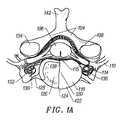
- FIGS. 1A and 1Billustrate a cross-sectional anatomical view of a vertebra and associated disc and a lateral view of a portion of a lumbar and thoracic spine, respectively. Structures of a typical cervical vertebra (superior aspect) are shown in FIG.
- 104lamina
- 106spinal cord
- 108distal root of spinal nerve
- 114ventral root of spinal nerve
- 115posterior longitudinal ligament
- 118intervertebral disc
- 120nocleus pulposus
- 122annulus fibrosus
- 124anterior longitudinal ligament
- 126verebral body
- 128pedicle
- 130verebral artery
- 132verebral veins
- 134superior articular facet
- 136posterior lateral portion of the annulus
- 138posterior medial portion of the annulus
- 142spinous process.
- one side of the intervertebral disc 118is not shown so that the anterior vertebral body 126 can be seen.
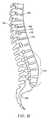
- FIG. 1Bis a lateral aspect of the lower portion of a typical spinal column showing the entire lumbar region and part of the thoracic region and displaying the following structures: 162 —intervertebral disc; 142 —spinous process; 168 —inferior articular process; 170 —inferior vertebral notch; 174 —superior articular process; 176 —lumbar curvature; and 180 —sacrum.
- FIG. 1Cprovides a posterior-lateral anatomical view of two lumbar vertebrae and illustration of the triangular working zone.
- the inferior articular process 168along with the pedicle 128 and the lumbar spinal nerve 110 , form a small “triangular” window through which introduction of an instrument can be achieved from the posterior lateral approach.
- FIG. 1Dillustrates an instrument (an introducer 169 ) introduced into an intervertebral disc by the posterior lateral approach.
- FIG. 1Eillustrates the anatomy of an intervertebral disc in greater detail and shows an introducer 169 inserted into the disc. Structures of the disc are identified and described by these anatomical designations: the posterior lateral inner annulus 136 , posterior medial inner annulus 138 , annulus fibrosus 122 /nucleus pulposus 120 interface, the annulus/dural interface 146 , annulus/posterior longitudinal ligament interface 148 , anterior lateral inner annulus 150 , and the anterior medial inner annulus 152 .
- the annulus fibrosus 122is comprised primarily of tough fibrous material, while the nucleus pulposus 120 is comprised primarily of an amorphous colloidal gel. There is a transition zone between the annulus fibrosus 122 and the nucleus pulposus 120 made of both fibrous-like material and amorphous colloidal gel. The border between the annulus fibrosus 122 and the nucleus pulposus 120 becomes more difficult to distinguish as a patient ages, due to degenerative changes. This process may begin as early as 30 years of age.
- the inner wall of the annulus fibrosuscan include the young wall comprised primarily of fibrous material as well as the transition zone which includes both fibrous material and amorphous colloidal gels (hereafter collectively referred to as the “inner wall of the annulus fibrosus”).
- the location at which there is an increase in resistance to probe penetration and which is sufficient to cause bending of the distal portion of the probe into a radius less than that of the internal wall 22 of the annulus fibrosusis considered to be the “inner wall of the annulus fibrosus”.
- stages 1-5degenerative disc disease
- Adams et al.“The Stages of Disc Degeneration as Revealed by Discograms,” J. Bone and Joint Surgery, 68, 36-41 (1986).
- the methods of instrument navigation described hereinwould probably not be able to distinguish between the nucleus and the annulus in degenerative disease of grade 5.
- most treatmentis expected to be performed in discs in stages 3 and 4, as stages 1 and 2 are asymptomatic in most patients, and stage 5 may require disc removal and fusion.
- the present inventionprovides devices and methods which are designed to more efficiently access and treat the interior of intervertebral discs by the posterior lateral approach.
- the present inventionrelates to various embodiments of intervertebral disc devices and their methods of use.
- the intervertebral disc devicecomprises a distal probe sized to be extended from a distal end of an introducer that is percutaneously delivered into an interior of an intervertebral disc, a distal section of the probe comprising a flexible neck which tapers in a proximal to distal direction, and a distal tip which is larger in cross sectional diameter than the flexible neck adjacent the distal tip, the flexible neck and distal tip serving to prevent the probe distal end from piercing an internal wall of the intervertebral disc; and a proximal handle for externally guiding the probe within an intervertebral disc.
- the flexible neckmay optionally be designed such that it is not predisposed to bending in any direction relative to a longitudinal axis of the probe.
- the flexible neckmay be designed to be predisposed to bending along a single plane relative to a longitudinal axis of the probe.
- the flexible neckmay be designed to be predisposed to bending in opposing directions along a single plane relative to a longitudinal axis of the probe.
- the flexible neckmay be designed to be predisposed to bending in at least two different directions along at least two different planes relative to a longitudinal axis of the probe.
- the flexible neckmay optionally have a round cross section.
- the flexible neckmay optionally have at least one flat surface extending along a longitudinal axis of the neck.
- the flexible neckhas two flat surfaces extending along a longitudinal axis of the neck on opposing sides of the neck.
- the neckmay optionally be formed of a flexible coil.
- the distal tipmay optionally have a larger cross sectional diameter than a largest cross sectional diameter of the flexible neck.
- the distal tipmay be symmetrical or asymmetrical.
- the distal tipis dome shaped or has a flat surface perpendicular to a longitudinal axis of the probe.
- the distal tipmay be attached to the neck of the probe by a variety of mechanisms including, for example, a spring or a pivot mechanism such as a ball and socket mechanism.
- the flexibility of the neck of the probeis designed such that it causes the probe to bend and the distal tip to trail behind a portion of the probe as the probe is advanced through tissue within an intervertebral disc.
- the shape of the distal tipmay also contribute to the distal tip trailing behind a portion of the probe.
- an intervertebral disc devicecomprising: a distal probe sized to be extended from a distal end of an introducer that is percutaneously delivered into an interior of an intervertebral disc, a distal section of the probe comprising an active electrode and a return electrode which are each spirally wrapped around the probe such that there are multiple alternating bands of the same active and return electrodes positioned longitudinally along the length of the distal section of the probe, the active and return electrodes being adapted to deliver bipolar electromagnetic energy to tissue within the intervertebral disc; and a proximal handle for externally guiding the probe within an intervertebral disc.
- the distal section of the probemay be predisposed to forming a loop.
- an intervertebral disc devicecomprising: a distal probe sized to be extended from a distal end of an introducer that is percutaneously delivered into an interior of an intervertebral disc, a distal section of the probe being predisposed to forming a loop when extended from the distal end of the introducer, the looping portion of the probe comprising an active electrode and a return electrode which are positioned on the probe such that the active and return electrodes are on opposing sides of the probe loop; and a proximal handle for externally guiding the probe within an intervertebral disc.
- an intervertebral disc devicecomprising: a distal probe sized to be extended from a distal end of an introducer that is percutaneously delivered into an interior of an intervertebral disc, a distal section of the probe comprising separate active and return electrode elements which are predisposed to bending away from each other when extended from the distal end of the introducer; and a proximal handle for externally guiding the probe within an intervertebral disc.
- an intervertebral disc devicecomprising: a distal sheath sized to be extended from a distal end of an introducer that is percutaneously delivered into an interior of an intervertebral disc, a distal section of the sheath being predisposed to adopting a bent configuration when extended from the introducer; a probe adapted to be extended from a distal end of the sheath, the bent section of the sheath causing the probe to adopt a same bent configuration; and a proximal handle for externally guiding the probe within an intervertebral disc.
- an intervertebral disc devicecomprising: a distal sheath sized to be extended from a distal end of an introducer that is percutaneously delivered into an interior of an intervertebral disc, a distal section of the sheath being predisposed to adopting a bent configuration when extended from the introducer; a guide wire adapted to be extended from a distal end of the sheath, the bent section of the sheath causing the guide wire to adopt a same bent configuration; a probe adapted to be extended from a distal end of the sheath over the guide wire, the bent section of the sheath causing the probe to adopt a same bent configuration; and a proximal handle for externally guiding the probe within an intervertebral disc.
- a distal section of the probecomprises an active electrode and a return electrode which are each spirally wrapped around the probe such that there are multiple alternating bands of the same active and return electrodes positioned longitudinally along the length of the distal section of the probe, the active and return electrodes being adapted to deliver bipolar electromagnetic energy to tissue within the intervertebral disc.
- the distal section of the probemay be predisposed to forming a loop.
- the looping portion of the probemay comprise an active electrode and a return electrode which are positioned on the probe such that the active and return electrodes are on opposing sides of the probe loop.
- a distal section of the probecomprises separate active and return electrode elements which are predisposed to bending away from each other when extended from the distal end of the introducer.
- an intervertebral disc devicecomprising: a probe capable of being extended from a distal end of an introducer that is percutaneously delivered into an interior of an intervertebral disc, the probe forming a loop when extended from the distal end of the introducer, the loop having first and second proximal ends external to the introducer which are brought together adjacent the introducer distal end to form the loop by the proximal ends being either attached to or entering the distal end of the introducer; and a proximal handle for externally causing the probe to be extended from the distal end of the introducer and externally guiding the probe within an intervertebral disc.
- the devicemay optionally further include an introducer, the first proximal end of the probe being attached to the introducer adjacent a distal end of the introducer, the second proximal end of the probe being extendable from the introducer distal end to form the loop.
- the first proximal end of the probemay optionally be attached to the introducer adjacent the distal end of the introducer by a guide wire lead.
- the first and second proximal ends of the probemay each be separately extendable from the introducer distal end to form the loop.
- the first and second proximal ends of the probemay have different cross sectional geometries.
- the different cross sectional geometries of the first and second proximal endsmay be selected such that the cross sectional geometry of the first proximal end is a compliment of the cross sectional geometry of the second proximal end.
- an intervertebral disc devicecomprising: a guide wire capable of being extended from a distal end of an introducer that is percutaneously delivered into an interior of an intervertebral disc, the guide wire forming a loop when extended from the distal end of the introducer, the loop having first and second proximal ends external to the introducer which are brought together adjacent the introducer distal end to form the loop by the proximal ends being either attached to or entering the distal end of the introducer; a probe capable of being extended over the guide wire from the distal end of the introducer; and a proximal handle for externally causing the guide wire and probe to be extended from the distal end of the introducer and externally guiding the guide wire and probe within an intervertebral disc.
- the devicefurther includes an introducer, the first proximal end of the guide wire being attached to the introducer adjacent a distal end of the introducer, the second proximal end of the guide wire being extendable from the introducer distal end to form the loop.
- the first and second proximal ends of the guide wireare each separately extendable from the introducer distal end to form the loop.
- an intervertebral disc devicecomprising: guide wire capable of being extended from a distal end of an introducer that is percutaneously delivered into an interior of an intervertebral disc, a distal section of the guide wire being predisposed to forming a loop when extended from the distal end of the introducer, the looped distal section of the guide wire serving to localize the looped distal section within the intervertebral disc; a probe capable of being extended over the guide wire from the distal end of the introducer, the probe and guide wire being extendable in combination such that position of the looped distal section of the guide wire is not changed; and a proximal handle for externally causing the guide wire and probe to be extended from the distal end of the introducer and externally guiding the guide wire and probe within an intervertebral disc.
- the devicemay further include flexible tubing operably interconnecting the proximal handle with the distal probe.
- the probe and/or guide wiremay optionally extend within the flexible tubing to the handle.
- the devicemay further include a connector system which enables an introducer to be removeably attached to the connector system, the probe being positionable within the introducer for delivery within the intervertebral disc with the assistance of the introducer.
- the devicemay further include a probe or guide wire with a mechanism for securing the probe or guide wire within the selected section of the intervertebral disc.
- the mechanismmay be a curved portion adjacent the distal end capable of anchoring the probe or guide wire into tissue.
- the curved distal portionpreferably forms a distal end of the probe or guide wire.
- the curved distal portionis optionally retractable and optionally divides into multiple separate curved portions, such as to form a treble hook.
- the probemay further include a functional element which performs a function.
- a functional elementwhich performs a function.
- functionsmay be performed by the functional element including, but not limited to, transmitting energy to tissue within an intervertebral disc, delivering material to within an intervertebral disc, and removing material within an intervertebral disc.
- the probemay further include an electromagnetic energy device capable of supplying energy within the intervertebral disc.
- the electromagnetic energy devicemay be capable of delivering energy selected from group consisting of coherent and incoherent light and radiofrequency (RF), microwave, and ultrasound waves.
- RFradiofrequency
- the electromagnetic energy devicecomprises electrodes adapted to deliver RF energy.
- the RF electrodesmay adopt a monopolar or bipolar configuration.
- the electromagnetic energy devicemay also comprise a resistive heating mechanism.
- the handlemay further comprise a probe control element for controlling the movement of the probe adjacent a distal end of the device.
- the devicemay also comprise a guide wire control element for controlling the movement of the guide wire adjacent a distal end of the device.
- Methodsare also provided for employing the various devices of the present invention to treat an interior of an intervertebral disc.
- the methodcomprises inserting an introducer through a skin of a person such that the distal end of the introducer travels within the person via a posterior lateral approach to an intervertebral disc such that a distal end of the introducer is positioned in or adjacent an intervertebral disc; extending a probe from a distal end of the introducer such that the probe is positioned within the intervertebral disc; and treating tissue within the interior of the intervertebral disc using the probe.
- the probe that is extended from the introducermay have any of the various probe designs described herein.
- the methodcomprises inserting an introducer through a skin of a person such that the distal end of the introducer travels within the person via a posterior lateral approach to an intervertebral disc such that a distal end of the introducer is positioned in or adjacent an intervertebral disc; extending a guide wire from a distal end of the introducer such that the guide wire is positioned within the intervertebral disc; extending a probe over the guide wire, and treating tissue within the interior of the intervertebral disc using the probe.
- the guide wire and probe that are extended from the introducermay have any of the various guide wire and probe designs described herein.
- a method for delivering a probecomprises extending a guide wire into an intervertebral disc such that the guide wire is positioned within the intervertebral disc adjacent an inner wall of the disc; attaching a distal portion of the guide wire to the inner wall; and extending a probe over the guide wire.
- the guide wire and probe that are extendedmay have any of the various guide wire and probe designs described herein.
- the step of attaching the distal portion of the guide wiremay be accomplished by inserting a portion of the guide wire into the tissue of the inner wall of an intervertebral disc such that the distal portion is held in place and retained by the tissue of the inner wall of the disc.
- a variety of attachment mechanismsmay be employed.
- the step of attaching the distal portion of the guide wiremay be by hooking the attachment mechanism into the tissue of the inner wall such that the distal portion is held in place and retained by the tissue of the inner wall of the disc.
- the attachment mechanismmay be a curved distal portion of the guide wire.
- All of the above embodiments involving attaching the guide wire to the inner wall of an intervertebral discmay be adapted where the probe instead of the guide wire comprises an attachment mechanism for attaching the probe to the inner wall.
- FIG. 1Aprovides a superior cross-sectional anatomical view of a cervical disc and vertebra.
- FIG. 1Bprovides a lateral anatomical view of a portion of a lumbar spine.
- FIG. 1Cprovides a posterior-lateral anatomical view of two lumbar vertebrae and illustration of the triangular working zone.
- FIG. 1Dprovides a superior cross-sectional view of the required posterior lateral approach.
- FIG. 1Eillustrates the anatomy of an intervertebral disc in greater detail and shows an introducer inserted into the disc.
- FIG. 2illustrates an embodiment of an intervertebral disc device system.
- FIG. 3Aillustrates a distal section of a probe with a flexible neck and a blunt distal tip.
- FIG. 3Billustrates a sequence demonstrating the flexing of the flexible neck of the probe.
- FIG. 3Cillustrates a distal section of a probe with a rounded neck.
- FIG. 3Dillustrates a neck which has been flattened on one side.
- FIG. 3Eillustrates a neck which has been flattened on two opposing sides.
- FIG. 3Fillustrates a neck where the neck is formed of a coil.
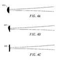
- FIGS. 4A-4Cillustrate a series of different distal tips which may be attached to the distal sections of the probes employed in the devices of the present invention.
- FIG. 4Aillustrates a dome shaped distal tip where the distal tip is symmetrical about the longitudinal axis of the distal section of the probe.
- FIG. 4Billustrates an offset dome shaped distal tip where the distal tip is asymmetrical about the longitudinal axis of the distal section of the probe.
- FIG. 4Cillustrates an flat distal tip.
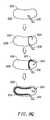
- FIGS. 5A-5Cillustrate a series of different distal tip attachment mechanisms which may be used to attach a distal tip to a distal section of a probe employed in the devices of the present invention.
- FIG. 5Aillustrates an embodiment where the distal tip and the neck of the distal section is one unit made of the same material.
- FIG. 5Billustrates an embodiment where the distal tip and the neck of the distal section are attached to each other by a pivot mechanism.
- FIG. 5Cillustrates an embodiment where the distal tip and the neck of the distal section are attached to each other by a spring.
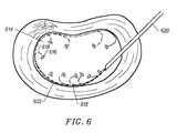
- FIG. 6illustrates movement with bending of a distal section within nucleous pulposus as the distal section of the device is advanced within the intervertebral disc.
- FIGS. 7A-7Cillustrate a sequence which shows how tissue force resisting the forward advancement of the probe within the intervertebral disc causes the distal section of the probe to bend.
- FIG. 7Ashows a probe with an asymmetrical distal tip.
- FIG. 7Billustrates that the asymmetrical resistance causes the distal section of the probe to bend.
- FIG. 7Cillustrates that further bending of the probe causes tissue force to be applied to the back of the distal tip as the distal section is advanced further.
- FIGS. 8A-8Qillustrate a series of different embodiments for deploying the distal section of the probe from the introducer so that the probe approaches the internal wall of the annulus fibrosus.
- FIG. 8Aillustrates an embodiment where the distal end of the probe is attached to the distal end of the introducer.
- FIG. 8Billustrates that the probe shown in FIG. 8A may be extended out of the distal end of the introducer to cause the probe to form a loop.
- FIG. 8Cillustrates another embodiment where the distal end of the probe is attached to the distal end of the introducer via a guide wire lead.
- FIG. 8Dillustrates that the probe shown in FIG. 8C may be extended out of the distal end of the introducer to cause the probe to form a loop.
- FIG. 8Eillustrates another embodiment where the distal end of the probe forms a loop within the introducer where both sides of the probe are separately extendable and retractable relative to the distal end of the introducer.
- FIG. 8Fillustrates that the probe shown in FIG. 8E may be extended out of the distal end of the introducer to cause the probe to form a loop.
- FIG. 8Gillustrates another embodiment where a guide wire is attached to the distal end of the introducer.
- FIG. 8Hillustrates the extension of a guide wire.
- FIG. 8Iillustrates that the probe shown in FIG. 8G may be extended along the guide wire out of the distal end of the introducer.
- FIG. 8Jillustrates another embodiment where a guide wire forms a loop within the introducer where both sides of the guide wire loop are separately extendable and retractable relative to the distal end of the introducer.
- FIG. 8Killustrates that extension of the guide wire shown in FIG. 8J out of the distal end of the introducer causes the guide wire to form a loop.
- FIG. 8Lillustrates that a probe may be extended along the guide wire shown in FIG. 8K out of the distal end of the introducer.
- FIGS. 8M-8Oillustrate another embodiment of the embodiment shown in FIG. 8J where the guide wire is capable of being folded upon itself.
- FIG. 8Millustrates the guide wire unfolded where section I includes a guide wire with a thin, concave shape, section II includes a tapered section that provides an area where the guide wire is folded upon itself, and section III includes a rounded section such that the rounded section fits within the concave shape of section I.
- FIG. 8Nshows the cross sections of guide wire sections I-III illustrated in FIG. 8 M.
- FIG. 8Oillustrates that the guide wire may be folded upon itself where the crease is at section II, and section I and section III come together.
- FIG. 8Pprovides a sequence illustrating the deployment of the guide wire from an introducer within a disc such that the guide wire encircles the internal wall of the disc.
- FIG. 8Qillustrates yet another embodiment where a guide wire and probe are used in combination to deploy the probe adjacent an internal wall of a disc.
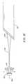
- FIGS. 9A-9Cillustrate one embodiment where a sheath having a predefined curvature adjacent its distal end introduces curvature to a guide wire or probe extended from the sheath.
- FIG. 9Aillustrates the distal end of an introducer with a sheath and a probe extending from the introducer.
- FIG. 9Billustrates the sheath being extend from the distal end of the introducer.
- FIG. 9Cillustrates the probe being extended beyond the sheath.
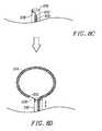
- FIGS. 10A-10Cillustrate a series of preferred designs for thermal energy delivery devices which may be used in combination with the devices of the present invention.
- FIG. 10Aillustrates an embodiment where the thermal energy delivery device is a bipolar electrode comprising an active electrode and a return electrode where the active and return electrodes are each spirally wrapped around a portion of the distal section of the probe.
- FIG. 10Billustrates another embodiment of a thermal energy delivery device where the active and return electrodes are positioned on opposing sides of the loop.
- FIG. 10Cillustrates another embodiment of a thermal energy delivery device.
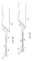
- FIGS. 11A and 11Billustrate yet another embodiment for a thermal energy delivery device which may be used in combination with the devices of the present invention.
- FIG. 11Aillustrates an embodiment where a pair of probes which form a return electrode and an active electrode extend from an introducer or sheath and are spaced apart from each other.
- FIG. 11Billustrates a variation on the embodiment shown in FIG. 11A where the pair of probes which form an active electrode and return electrode diverge from each other adjacent their distal ends.
- FIG. 12shows an embodiment of the guide wire with an attachment mechanism at the distal tip for attaching the guide wire to the inner wall of the intervertebral disc.
- the present inventionprovides methods and devices for accessing and treating intervertebral discs.
- the devices according to the present inventionare externally guidable percutaneous intervertebral disc devices. As such, these devices are used to traverse the patent's skin and access an intervertebral disc through the tissue positioned between the patient's skin and the intervertebral disc. Entry into the intervertebral disc is achieved by a posterior lateral approach.
- FIG. 2illustrates an embodiment of an overall system for treating intervertebral discs which incorporates devices of the present invention. It is noted that many of the subcomponents of the devices of the present invention, as well as their operation are described in further detail in U.S. Pat. Nos. 6,135,999; 6,126,682; 6,122,549; 6,099,514; 6,095,149; 6,073,051; 6,007,570; 5,980,504, which are each incorporated herein by reference.
- FIG. 2depicts but one embodiment of the overall system.
- systems incorporating the devices of the inventioncan be prepared in a number of different forms and can consist (for example) of a single instrument with multiple internal parts or a series of instruments that can be replaceably and sequentially inserted into a hollow fixed instrument (such as a needle) that guides the operational instruments to a selected location within the intervertebral disc.
- a hollow fixed instrumentsuch as a needle
- the proximal end 210 of the systemcomprises a handle 212 which includes a guide wire control element 214 for controlling the movement of a guide wire adjacent a distal end 218 of the device and a probe body control element 216 for controlling the movement of a probe (not shown) adjacent the distal end 218 of the device.
- the handle 212further includes one or more mechanisms 224 (not shown in detail) for attaching different external tools (e.g., energy sources, material delivery and removal mechanisms (e.g., a pump), visualization tools, etc.) to the device.
- different external toolse.g., energy sources, material delivery and removal mechanisms (e.g., a pump), visualization tools, etc.
- Flexible tubing 226attaches the handle 212 to a connector system 228 which remains external to the body.
- the connector system 228may allow different external tools to be attached to the device.
- a fluid injection tool 232is depicted.
- a probe and a guide wiremay optionally extend from a distal portion of the device through the flexible tubing to the handle. Alternatively, only mechanisms for controlling the probe and guide wire may extend from the distal portion of the device through the flexible tubing to the handle.
- Insertion of flexible tubing between the handle 212 and the connector system 228serves to physically isolate movements of the handle 212 from the portion of the device which is inserted into the patient. As a result, the patient is less prone to perceive a manipulation of the device within the patient as a result of movement of the handle.
- the distal portion of the devices of the present inventionmay be delivered through the skin of a patient and into an intervertebral disc using techniques typical of percutaneous interventions.
- the connector system 228allows an introducer 230 to be removably coupled to the device to facilitate delivery of the distal portion of the device through a patient's skin to within an intervertebral disc.
- a luer fitting 234may be used as the attachment mechanism for the introducer.
- introduceris used herein to indicate that the device of the invention can be used with any insertional apparatus that provides proximity to the disc, including many such insertional apparatuses known in the art.
- An introducerhas an internal introducer lumen with a distal opening 238 at a terminus of the introducer to allow insertion (and manipulation) of the operational parts of the device into (and in) the interior of a disc.
- the introducerin its simplest form, can consist of a hollow needle-like device (optionally fitted with an internal removable obturator or trocar to prevent clogging during initial insertion) or a combination of a simple exterior cannula that fits around a trocar.
- the resultis essentially the same: placement of a hollow tube (the needle or exterior cannula after removal of the obturator or trocar, respectively) through skin and tissue to provide access into the annulus fibrosus.
- the hollow introduceracts as a guide for introducing instrumentation. More complex variations exist in percutaneous instruments designed for other parts of the body and can be applied to design of instruments intended for disc operations. Examples of such obturators are well known in the art.
- a particularly preferred introduceris a 17- or 18-gauge, thin-wall needle with a matched obturator, which after insertion is replaced with a probe of the present invention.
- the devices of the present inventionfurther include a probe 236 which may be extended and retracted relative to the distal opening 238 of the introducer 230 .
- a distal section of the probe 236is shown to be retracted into the introducer in FIG. 2 (above) as well as extended from the distal end of the introducer (below).
- the probe 236is intended to be located inside the disc.
- the introducer 169pierces the annulus fibrosus 122 and is advanced through the wall of the annulus fibrosus into the nucleus pulposus 120 .
- the introducer 169is extended a desired distance into nucleus pulposus 120 .
- the distal section of the probe 236is advanced through a distal end of introducer 169 into nucleus pulposus 120 .
- probe devicesaccess a section of tissue in the patient's body by being delivered within the lumen of a body vessel such as a vein or artery.
- a body vesselsuch as a vein or artery.
- the devices of the present inventiondo not rely upon accessing a section of tissue in the patient's body by being delivered within the lumen of a body vessel. Rather, “probe” is used herein to describe the distal portion of the device which is extended into the intervertebral disc from the introducer.
- the probemay optionally include functional elements which perform different functions, such as transmitting energy and/or material from a location external to the body to a location internal to the disc being accessed upon. Alternatively, material can be transported in the other direction to remove material from the disc, such as removing material by aspiration.
- the deviceallows the functional elements to be controllably positioned and manipulated within the guided by manipulation of the handle.
- the probeis adapted to slidably advance through the introducer lumen, the probe having a distal section which is extendible through the distal opening at the terminus of the introducer into the disc.
- a typical distance of extensionis at least one-half the diameter of the nucleus pulposus, preferably in the range of one-half to one and one-half times the circumference of the nucleus.
- the distal section of the probeis manufactured with sufficient rigidity to avoid collapsing upon itself while being advanced through the nucleus pulposus.
- the distal sectionhas insufficient rigidity to puncture the annulus fibrosus under the same force used to advance the probe through the nucleus pulposus and around the inner wall of the annulus fibrosus.
- Absolute penetration abilitywill vary with sharpness and stiffness of the distal tip of the distal section, but in all cases, a probe of the present invention will advance more readily through the nucleus pulposus than through the annulus fibrosus.
- the inability of the distal section of the probe to pierce the annuluscan be the result of either the shape of the distal tip of the probe and/or the flexibility of distal portion.
- the distal tipis considered sufficiently blunt when it does not penetrate the annulus fibrosus but is deflected back into the nucleus pulposus or to the side around the inner wall of the annulus when the distal tip is advanced.
- the devices according to the present inventioncomprise multiple novel features including, but not being limited to (a) flexible necks adjacent the distal ends of the devices, (b) distal tips which facilitate navigation of the device within an intervertebral disc, (c) attachment mechanisms for the distal tips to the necks, (d) energy delivery mechanisms used with the devices for treating intervertebral discs, and (e) mechanisms for deploying the probe distal end within an intervertebral disc.
- One feature of the probe employed in the device of the present inventionis the inability of the distal section of the probe to pierce the annulus. This may be achieved either by the design of the neck of the probe, (i.e., the section of the distal section proximal to the distal tip) or by the design of the distal tip of the probe. The design of the neck and distal tip of the probe can also be utilized to facilitate navigation of the device within the intervertebral disc.
- FIG. 3Ashows a distal section 310 of a probe with a flexible neck 312 which tapers from a proximal portion 314 of the distal section.
- a blunt distal tip 316is positioned on a distal end of the distal section 310 .
- the distal end of an introducer 318 from which the probe distal section extendsis also illustrated. It is noted that the probe distal section is preferably retractable and extendable 320 relative to the distal end of the introducer.
- FIG. 3Billustrates a sequence which shows how the forward advancement of the distal section 310 of a probe from an introducer 318 against tissue causes the probe to bend at the neck 312 relative to the longitudinal axis 324 of the distal section 310 .
- further extension 320 of the probe against the tissuecauses the distal section 310 of the probe to bend further relative to the longitudinal axis 324 of the distal section 310 .
- FIG. 3Cillustrates an embodiment where the neck 312 is rounded.
- the distal sectionexhibits no predisposition with regard to the direction in which the neck bends, as indicated by the arrows.
- a rounded as tapered endbending in any direction relative to the longitudinal axis of the distal section can be achieved.
- FIG. 3Dillustrates a neck 312 which has been flattened on one side 322 .
- Flattening the neck on one sidecauses the distal section to be predisposed to bending in the plane perpendicular to the flattened surface toward the side of the flattened surface.
- the neckis predisposed to bend in a particular direction relative to the longitudinal axis of the distal section.
- FIG. 3Eillustrates a neck 312 which has been flattened on two opposing sides 324 , 326 .
- Flattening the neck on the two opposing sidescauses the distal section to be predisposed to bending in planes perpendicular to the two flattened surfaces. If both flattened surfaces are parallel to each other, the neck will preferentially bend in the same plane (as illustrated). If the two flattened surfaces are not parallel to each other, the neck will preferentially bend in the plane perpendicular to the first flattened surface or the plane perpendicular to the second flattened surface.
- FIG. 3Fillustrates a neck 312 where the neck is formed of a coil.
- the coil necklike the rounded neck, allows the distal section to bend with no predisposition with regard to which direction the neck bends. Hence, by using a coiled neck, bending in any direction relative to the longitudinal axis of the distal section can be achieved.
- FIGS. 4 A— 4 Cillustrate a series of different distal tips which may be attached to the distal sections of the probes employed in the devices of the present invention.
- FIG. 4Aillustrates a dome shaped distal tip 412 where the dome is symmetrical about the longitudinal axis of the distal section of the probe.
- the tipBy having the tip be dome shaped, the tip has less resistance when being pushed through the nucleous pulposus. Meanwhile, by causing the distal tip to be symmetrical, the distal tip does not introduce a predisposition for the distal section to bend in any particular direction.
- FIG. 4Billustrates an offset dome shaped distal tip 414 where the dome is asymmetrical about the longitudinal axis of the distal section of the probe.
- FIG. 4Cillustrates a flat distal tip 416 .
- the resistance felt by the distal tip when pushed through the nucleous pulposusis enhanced.
- a predisposition for the distal section to bend in a particular directioncan be imparted by designing the distal tip to be asymmetrical relative to the longitudinal axis of the distal section.
- FIGS. 5A-5Cillustrate a series of different distal tip attachment mechanisms which may be used to attach a distal tip to a distal section of a probe employed in the devices of the present invention.
- Each of these different distal tip attachment mechanismscauses the distal tip and the distal section of the probe to move through the dense colloidal material of the nucleous pulposus.
- FIG. 5Aillustrates an embodiment where the distal tip 512 and the neck 514 of the distal section is one unit made of the same material.
- the distal tipis rigid relative to the neck 514 of the distal section.
- FIG. 5Billustrates an embodiment where the distal tip 512 and the neck 514 of the distal section are attached by a pivot mechanism 516 , such as a ball and socket mechanism, which allows the orientation of the distal tip to rotate relative to the neck 514 .
- a pivot mechanism 516such as a ball and socket mechanism
- FIG. 5Cillustrates an embodiment where the distal tip 512 and the neck 514 of the distal section are attached by a spring 518 .
- a spring mechanism 518not only allows the distal tip 512 to rotate relative to the neck 514 , the spring mechanism also allows the distal tip to be distended away from the neck 514 .
- FIG. 6illustrates movement with bending of a distal section 612 within nucleous pulposus 614 as the probe distal section is advanced within the intervertebral disc.
- the introducer 620remains stationary as the probe is advanced.
- the distal tip 616 and neck 618are bent away from the intervertebral wall 622 . This may be accomplished either by predisposing the tip and/or neck to bending in a particular direction. It may also be accomplished by the wall itself having a certain curvature.
- the distal sectionbends until the tension created by the bending exceeds the force that is being applied to the distal section by the tissue to cause the bending.
- the rigidity of the flexible distal sectionlimits the amount that the distal section ultimately bends.
- FIGS. 7A-7Cillustrate a sequence which shows how tissue force resisting the forward advancement of the probe within the intervertebral disc causes the distal section of the probe to bend.
- FIG. 7Ashows a probe 710 with an asymmetrical distal tip 712 . As illustrated, the asymmetry of the tip causes more resistance to be applied to the larger side of the asymmetrical distal tip 712 . As illustrated in FIG. 7B, the asymmetrical resistance causes the distal section of the probe to bend. As the distal section is advanced further, force begins to be applied to the back of the distal tip, causing the distal section to bend further. As the distal section is advanced further, more force is applied to the distal tip 712 , as shown by the arrows in FIG. 7C against the distal tip 712 .
- FIGS. 8A-8Qillustrate a series of different embodiments for deploying the distal section of the probe from the introducer so that the probe approaches the internal wall of the annulus fibrosus.
- FIG. 8Aillustrates an embodiment where the distal end 812 of the probe 814 is attached to the distal end of the introducer 816 .
- extension of the distal end 812 of the probe 814 out of the distal end of the introducer 816 in this embodimentcauses the probe to form a loop. Broadening of the loop by further extension of the probe causes the probe to encircle the internal wall 22 of the annulus fibrosus.
- FIG. 8Cillustrates another embodiment where the distal end 812 of the probe 814 is attached to the distal end of the introducer 816 via a guide wire lead 818 .
- the guide wire lead 818is thinner than the probe 814 and thus can adopt a smaller radius of curvature than the probe 814 .
- Thisallows a smaller bore introducer 816 to be utilized or a larger probe 814 to be utilized since both the distal end of the probe and the guide wire lead can be more readily accommodated within the introducer.
- extension of the distal end 812 of the probe 814 out of the distal end of the introducer 816 in this embodimentcauses the probe to form a loop. Broadening of the loop by further extension of the probe causes the probe to encircle the internal wall of the annulus fibrosus.
- FIG. 8Eillustrates another embodiment where the distal end of the probe 814 forms a loop within the introducer where both sides of the probe 814 are separately extendable and retractable relative to the distal end of the introducer 816 .
- extension of the probe 814 out of the distal end of the introducer 816 in this embodimentcauses the probe to form a loop.
- Shown as boxes on the probeare a series of electrodes 820 for delivering energy to tissue within the disc. It is noted that other functional elements can also be positioned on the probe. Broadening of the loop by further extension of the probe causes the probe to encircle the internal wall of the annulus fibrosus. Extending or retracting one side of the loop shaped probe causes the electrodes to move relative to the inner wall.
- FIG. 8Gillustrates another embodiment where a guide wire 824 is attached to the distal end of the introducer 816 .
- the guide wire 824is thinner than the probe 814 and thus can adopt a smaller radius of curvature than the probe 814 . This allows a smaller bore introducer 816 to be utilized or a larger probe 814 to be utilized since both the distal end of the probe and the guide wire lead can be more readily accommodated within the introducer.
- extension of the guide wire 824 out of the distal end of the introducer 816 in this embodimentcauses the guide wire 824 to form a loop.
- a probe 814may be extended along the guide wire 824 out of the distal end of the introducer.
- the probe 814may include different functional elements for treating tissue within the disc.
- FIG. 8Jillustrates another embodiment where a guide wire 824 forms a loop within the introducer where both sides of the guide wire loop 824 are separately extendable and retractable relative to the distal end of the introducer 816 .
- the guide wire 824is thinner than the probe 814 and thus can adopt a smaller radius of curvature than the probe 814 . This allows a smaller bore introducer 816 to be utilized or a larger probe 814 to be utilized since both the distal end of the probe and the guide wire lead can be more readily accommodated within the introducer.
- extension of the guide wire 824 out of the distal end of the introducer 816 in this embodimentcauses the guide wire 824 to form a loop.
- a probe 814may be extended along the guide wire 824 out of the distal end of the introducer.
- the probe 814may include different functional elements for treating tissue within the disc.
- FIGS. 8M-8Oillustrate another embodiment of the embodiment shown in FIG. 8J where the guide wire 824 is capable of being folded upon itself.
- FIG. 8Millustrates the guide wire unfolded where section I includes a guide wire with a thin, concave shape, section II includes a tapered section that provides an area where the guide wire is folded upon itself, and section III includes a rounded section such that the rounded section fits within the concave shape of section I.
- FIG. 8Nshows the cross sections of guide wire sections I-III illustrated in FIG. 8 M.
- the guide wiremay be folded upon itself where the crease is at section II, and section I and section III come together. By having sections I and III fit together, the folded guide wire can more readily be accommodated within an introducer.
- FIG. 8Pprovides a sequence illustrating the deployment of the guide wire 824 from an introducer 816 within a disc such that the guide wire 824 encircles the internal wall 828 of the disc 830 .
- the creaseallows the guide wire loop to be more tightly folded together.
- a side of the guide wirecan be expanded.
- the other side of the guide wire loopmay be expanded.
- sections I and III fit togetherallow for the different sides of the loop to be separately moved relative to each other and extended and retracted from the introducer.
- FIG. 8M-8Pare described with regard to guide wires, that the probe may also be designed with a crease so that it may be deployed in a similar manner as shown in FIGS. 8E, 8 F and then in FIG. 8 P.
- FIG. 8Qillustrates yet another embodiment where a guide wire 824 and probe 814 are used in combination to deploy the probe 814 adjacent an internal wall 828 of a disc 830 .
- an introducer 816is introduced into the disc.
- a guide wire 824is then extended from the introducer 816 .
- the guide wireis predisposed to forming a loop when extended from the introducer 816 and thus moves toward one side of the disc.
- a probe 814is then extended in combination with the guide wire from the introducer 816 .
- the looped distal end of the guide wire 824serves to immobilize the distal end of the guide wire. This then allows the probe 814 to be expanded, thereby causing the probe to move along the wall of the disc.
- the distal portion of the probe and/or the guide wiremay be pre-bent, if desired.
- Pre-bent or “biased”means that a portion of the probe, guide wire, or other structural element under discussion, is made of a spring-like material that is bent in the absence of external stress but which, under selected stress conditions (for example, while the probe is inside the introducer), is linear.
- the un-stressed wire loop diameterpreferably has a diameter between about 0.025-1 inch, more preferably between about 0.05-0.75 inch, or most preferably between about 0.1-0.5 inch.
- the diameter of the guide wirepreferably has a diameter between about 0.005-0.05 inch, more preferably between about 0.007-0.035 inch, or most preferably between about 0.009-0.025 inch.
- a biased distal portioncan be manufactured from either spring metal or super elastic memory material (such as Tinel.RTM. nickel-titanium alloy, Raychem Corp., Menlo Park Calif.).
- the introducer(at least in the case of a spring-like material for forming the probe) is sufficiently strong to resist the bending action of the bent distal end and maintain the biased distal portion in alignment as it passes through the introducer.
- a probe or guide wire with a biased distal portionencourages advancement of the probe or guide wire substantially in the direction of the bend relative to other lateral directions. Biasing the probe or guide wire distal end also further decreases likelihood that the distal end of the probe or guide wire will be forced through the annulus fibrosus under the pressure used to advance the probe.
- the distal section of the probe or guide wirecan be provided with a mechanical mechanism for deflecting the distal section, such as a wire that deflects the distal section in the desired direction upon application of force to the proximal end of the deflection wire.
- a mechanical mechanism for deflecting the distal sectionsuch as a wire that deflects the distal section in the desired direction upon application of force to the proximal end of the deflection wire.
- Any device in which bending of the distal end of a probe or guide wire is controlled by the physicianis “actively settable.”
- other methods of providing a bending force at the distal sectioncan be used, such as hydraulic pressure and electromagnetic force (such as heating a shaped memory alloy to cause it to contract). Any of a number of techniques can be used to provide selective bending of the probe in one lateral direction.
- a sheathmay be employed in combination with the probe (or guide wire) to facilitate directing movement of the probe within a disc.
- the sheathcan be made of a variety of different materials including but not limited to polyester, rayon, polyamide, polyurethane, polyethylene, polyamide and silicone.
- FIGS. 9A-9Cillustrate one embodiment where a sheath having a predefined curvature adjacent its distal end introduces curvature to a guide wire or probe extended from the sheath.
- FIG. 9Aillustrates the distal end of an introducer 912 with a sheath 914 and a probe 916 extending from the introducer 912 . It is noted that a guide wire could be used in place of the probe 916 , the probe being later drawn over the extended guide wire.
- FIG. 9Billustrates the sheath 914 being extended from the distal end of the introducer 912 .
- the sheath 914has a predefined curvature 918 adjacent its distal end. This curvature causes the probe 916 (or guide wire) to likewise be curved.
- the sheath 914is only extended a limited distance. Meanwhile, the probe is further extendible relative to the sheath 914 . This allows a degree of curvature to be maintained by the sheath at a known, preselected distance that is distal relative to the introducer. Meanwhile, the probe 916 can be extended further out of the sheath.
- the probeitself may optionally have its own preselected degrees of curvature.
- one or more functional elementsmay be provided in or on the distal section of the probe to carry out that purpose.
- Non-limiting examples of functional elementsinclude any element capable of aiding diagnosis, delivering energy, or delivering or removing a material from a location adjacent the element's location in or on the probe, such as an opening in the probe for delivery of a fluid (e.g., dissolved collagen to seal the fissure) or for suction, a thermal energy delivery device (heat source), a mechanical grasping tool for removing or depositing a solid, a cutting tool (which includes all similar operations, such as puncturing), a sensor for measurement of a function (such as electrical resistance, temperature, or mechanical strength), or a functional element having a combination of these functions.
- a fluide.g., dissolved collagen to seal the fissure
- a thermal energy delivery deviceheat source
- a mechanical grasping toolfor removing or depositing a solid
- a cutting toolwhich includes all similar operations, such as puncturing
- a sensor for measurement of a functionsuch as electrical resistance, temperature, or mechanical strength
- the functional elementcan be at varied locations on the distal section of the probe, depending on its intended use. Multiple functional elements can be present, such as multiple functional elements of different types (e.g., a heat source and a temperature sensor) or multiple functional elements of the same type (e.g., multiple heat sources spaced along the intradiscal portion).
- multiple functional elements of different typese.g., a heat source and a temperature sensor
- multiple functional elements of the same typee.g., multiple heat sources spaced along the intradiscal portion.
- thermal energy delivery deviceOne of the possible functional elements present on the distal section of the probe is a thermal energy delivery device.
- thermal energycan be delivered including but not limited to resistive heat, radiofrequency (RF), coherent and incoherent light, microwave, ultrasound and liquid thermal jet energies.
- the electrode array lengthis preferably 0.2-5 inches long, more preferably 0.4-4 inches long, and most preferably 0.5-3 inches long.
- Infusion lumenis configured to transport a variety of different media including but not limited to electrolytic solutions (such as normal saline), contrast media (such as Conray meglumine iothalamate), pharmaceutical agents, disinfectants, filling or binding materials such as collagens or cements, chemonucleolytic agents and the like, from a reservoir exterior to the patient to a desired location within the interior of a disc (i.e., the fissure).
- electrolytic solutionssuch as normal saline
- contrast mediasuch as Conray meglumine iothalamate
- pharmaceutical agentssuch as an aspiration lumen to remove nucleus material or excess liquid or gas (naturally present, present as the result of a liquefying operation, or present because of prior introduction) from the interior of a disc.
- irrigation lumenWhen used to transport a fluid for irrigation of the location within the disc, the infusion lumen is sometimes referred to as an irrigation lumen.
- Infusion lumencan be coupled to medium reservoir through the probe.
- one or more sensor lumensmay be included.
- An example of a sensor lumenis a wire connecting a thermal sensor at a distal portion of the probe to control elements attached to a connector in the proximal handle of the probe.
- Energy directing devicesmay also optionally be included, such as thermal reflectors, optical reflectors, thermal insulators, and electrical insulators.
- An energy directing devicemay be used to limit thermal and/or electromagnetic energy delivery to a selected site of the disc and to leave other sections of the disc substantially unaffected.
- An energy directing devicecan be positioned on an exterior surface of the distal section of the probe, as well as in an internal portion of the probe. For example, energy can be directed to the walls of a fissure to cauterize granulation tissue and to shrink the collagen component of the annulus, while the nucleus is shielded from excess heat.
- Therapeutic and/or diagnostic agentsmay be delivered within the disc via the probe.
- agents that may be deliveredinclude, but are not limited to, electromagnetic energy, electrolytic solutions, contrast media, pharmaceutical agents, disinfectants, collagens, cements, chemonucleolytic agents and thermal energy.
- the deviceincludes markings which indicate to the physician how far the probe has been advanced into the nucleus.
- markingscan be positioned on the handle or on the flexible tubing. Preferred are visible markings every centimeter to aid the physician in estimating the probe tip advancement.
- visible markingscan also be used to show twisting motions of the probe to indicate the orientation of the bending plane of the distal portion of the probe. It is preferred, however, to indicate the distal bending plane by the shape and feel of the proximal end of the probe assembly.
- the probecan be attached to or shaped into a handle that fits the hand of the physician and also indicates the orientation of the distal bending plane. Both the markings and the handle shape thus act as control elements to provide control over the orientation of the bending plane; other control elements, such as plungers or buttons that act on mechanical, hydrostatic, electrical, or other types of controls, can be present in more complex embodiments of the invention.
- a radiographically opaque marking devicecan be included in the distal portion of the probe (such as in the tip or at spaced locations throughout the intradiscal portion) so that advancement and positioning of the intradiscal section can be directly observed by radiographic imaging.
- radiographically opaque markingsare preferred when the intradiscal section is not clearly visible by radiographic imaging, such as when the majority of the probe is made of plastic instead of metal.
- a radiographically opaque markingcan be any of the known (or newly discovered) materials or devices with significant opacity.
- Examplesinclude but are not limited to a steel mandrel sufficiently thick to be visible on fluoroscopy, a tantalum/polyurethane tip, a gold-plated tip, bands of platinum, stainless steel or gold, soldered spots of gold and polymeric materials with radiographically opaque filler such as barium sulfate.
- a resistive heating element or an RF electrode(s)may provide sufficient radio-opacity in some embodiments to serve as a marking device.
- FIGS. 10A-10Cillustrate a series of preferred designs for bipolar thermal energy delivery devices which may be used in combination with the devices of the present invention. It is noted that radio frequency energy or resistive heating may be performed using these designs.
- FIG. 10Aillustrates an embodiment where the thermal energy delivery device is a bipolar electrode comprising an active electrode 1012 and a return electrode 1014 where the active electrode 1012 and return electrode 1014 are each spirally wrapped around a portion of the distal section of the probe 1016 .
- the probeis shown to be extending from an introducer 1018 .
- a potentialis introduced between the active electrode 1012 and return electrode 1014 , current flows through the tissue adjacent the two electrodes. Since the two electrodes are wrapped in a spiral about the active electrode, energy transfer is distributed along the length of the probe, thereby more evenly heating the adjacent tissue.
- the distal section of the probe 1016 shown in FIG. 10Ais predisposed to form a loop.
- the loopBy sizing the loop to approximate the inner diameter of an intervertebral disc, it is possible to cause the loop shaped probe to abut the internal wall of the disc. Then, by applying a potential between the electrodes, energy can be somewhat uniformly delivered to tissue adjacent the internal wall of the disc. It is noted that over time, tissue interior to the loop may also be uniformly treated by the loop shaped electrode.
- FIG. 10Billustrates another embodiment of a thermal energy delivery device.
- the distal section of the probe 1016is predisposed to form a loop.
- an active electrode 1012 and a return electrode 1014are positioned on opposing sides of the loop.
- FIG. 10Cillustrates another embodiment of a thermal energy delivery device.
- the distal section of the probe 1016is predisposed to form a loop.
- a series of alternating active 1012 and return 1014 electrodesare positioned along the distal section of the probe. By applying a potential between the series of active and return electrodes, energy can be delivered to tissue along the length of the probe.
- FIGS. 11A and 11Billustrate yet another embodiment for a thermal energy delivery device which may be used in combination with the devices of the present invention. It is noted that radio frequency energy or resistive heating may be performed using these designs.
- FIG. 11Aillustrates an embodiment where a pair of probes which form an active electrode 1112 and a return electrode 1114 extend from an introducer or sheath 1116 and are spaced apart from each other. By applying a potential between the active and return electrodes, energy can be delivered to tissue along the length of the probes.
- FIG. 11Billustrates a variation on the embodiment shown in FIG. 11A where the pair of probes which form an active electrode 1112 and a return electrode 1114 diverge from each other adjacent their distal ends.
- energycan be delivered to tissue along the length of the probes.
- a larger area of tissuemay be treated.
- thermocouple 1118for sensing temperature
- feedback loop 1120for regulating the potential between the electrodes in response to measurements by the thermocouple.
- the amount of thermal energy delivered to the tissueis a function of (i) the amount of current passing through heating element, (ii) the length, shape, and/or size of heating element, (iii) the resistive properties of heating element, (iv) the gauge of heating element, and (v) the use of cooling fluid to control temperature. All of these factors can be varied individually or in combination to provide the desired level of heat. Power supply associated with heating element may be battery based.
- the probecan be sterilized and may be disposable.
- thermal energyis delivered to a selected section of the disc in an amount that does not create a destructive lesion to the disc, other than at most a change in the water content of the nucleus pulposus.
- Sufficient thermal energyis delivered to the disc to change its biochemical and/or biomechanical properties without structural degradation of tissue.
- Thermal energymay be used to cauterize granulation tissue which is pain sensitive and forms in a long-standing tear or fissure. Additionally or alternatively, thermal energy is used to seal at least a part of the fissure. To do that, the disc material adjacent to the fissure is typically heated to a temperature in the range of 45-70 degree C. which is sufficient to shrink and weld collagen. In one method, tissue is heated to a temperature of at least 50 degree C. for times of approximately one, two, three minutes, or longer, as needed to shrink the tissue back into place.
- Global heating of the discalso can be used to cauterize the granulation tissue and seal the fissure.
- the heating elementis positioned away from the annulus but energy radiates to the annulus to raise the temperature of the tissue around the fissure. This global heating method can help seal a large area or multiple fissures simultaneously.
- FIG. 12shows an embodiment of the guide wire 1224 with a mechanism 1235 at the end of the distal portion 1212 of the guide wire for attaching the guide wire to the inner wall of the intervertebral disc.
- the guide wire 1224is extended into the intervertebral disc and navigated to a desired portion along the inner wall of the disc.
- the attachment mechanismis inserted and held in place such that the distal portion 1212 is attached to the inner wall tissue.
- extension of the probe 1214 over the guide wire into the nucleus 120 of the intervertebral disccauses the probe to move along the path of the guide wire.
- the attachment of the guide wire to the inner wallassists in keeping the guide wire in place despite force on the guide wire by the probe.
- the distal portion 1231 of the probe 1214is positioned at an annular fissure 44 for performing a function as described herein.
Landscapes
- Health & Medical Sciences (AREA)
- Surgery (AREA)
- Life Sciences & Earth Sciences (AREA)
- Engineering & Computer Science (AREA)
- Veterinary Medicine (AREA)
- General Health & Medical Sciences (AREA)
- Nuclear Medicine, Radiotherapy & Molecular Imaging (AREA)
- Public Health (AREA)
- Biomedical Technology (AREA)
- Heart & Thoracic Surgery (AREA)
- Medical Informatics (AREA)
- Molecular Biology (AREA)
- Animal Behavior & Ethology (AREA)
- Otolaryngology (AREA)
- Plasma & Fusion (AREA)
- Physics & Mathematics (AREA)
- Neurology (AREA)
- Neurosurgery (AREA)
- Pathology (AREA)
- Surgical Instruments (AREA)
- Prostheses (AREA)
Abstract
Description
Claims (29)
Priority Applications (5)
| Application Number | Priority Date | Filing Date | Title |
|---|---|---|---|
| US09/876,827US6638276B2 (en) | 2001-06-06 | 2001-06-06 | Intervertebral disc device employing prebent sheath |
| EP02737352AEP1395191A1 (en) | 2001-06-06 | 2002-06-04 | Intervertebral disc device employing prebent sheath |
| PCT/US2002/017543WO2002098314A1 (en) | 2001-06-06 | 2002-06-04 | Intervertebral disc device employing prebent sheath |
| JP2003501360AJP2004529721A (en) | 2001-06-06 | 2002-06-04 | Intervertebral disc device using a curved sheath |
| CA002449456ACA2449456A1 (en) | 2001-06-06 | 2002-06-04 | Intervertebral disc device employing prebent sheath |
Applications Claiming Priority (1)
| Application Number | Priority Date | Filing Date | Title |
|---|---|---|---|
| US09/876,827US6638276B2 (en) | 2001-06-06 | 2001-06-06 | Intervertebral disc device employing prebent sheath |
Publications (2)
| Publication Number | Publication Date |
|---|---|
| US20020188290A1 US20020188290A1 (en) | 2002-12-12 |
| US6638276B2true US6638276B2 (en) | 2003-10-28 |
Family
ID=25368655
Family Applications (1)
| Application Number | Title | Priority Date | Filing Date |
|---|---|---|---|
| US09/876,827Expired - LifetimeUS6638276B2 (en) | 2001-06-06 | 2001-06-06 | Intervertebral disc device employing prebent sheath |
Country Status (5)
| Country | Link |
|---|---|
| US (1) | US6638276B2 (en) |
| EP (1) | EP1395191A1 (en) |
| JP (1) | JP2004529721A (en) |
| CA (1) | CA2449456A1 (en) |
| WO (1) | WO2002098314A1 (en) |
Cited By (67)
| Publication number | Priority date | Publication date | Assignee | Title |
|---|---|---|---|---|
| US6767347B2 (en) | 1996-10-23 | 2004-07-27 | Oratec Interventions, Inc. | Catheter for delivery of energy to a surgical site |
| US20050004563A1 (en)* | 2003-07-01 | 2005-01-06 | Racz N. Sandor | Apparatus and methods for sensing and cooling during application of thermal energy for treating degenerative spinal discs |
| US6878155B2 (en) | 2000-02-25 | 2005-04-12 | Oratec Interventions, Inc. | Method of treating intervertebral disc tissue employing attachment mechanism |
| US20050152961A1 (en)* | 2000-06-22 | 2005-07-14 | Spinal Restoration, Inc. | Biological bioadhesive compositions and methods of preparation and use |
| US20050182317A1 (en)* | 2004-01-29 | 2005-08-18 | Haddad Souheil F. | Method and apparatus for locating medical devices in tissue |
| US20050240171A1 (en)* | 2004-04-23 | 2005-10-27 | Forrest Leonard E | Device and method for treatment of intervertebral disc disruption |
| US20060004369A1 (en)* | 2004-06-17 | 2006-01-05 | Scimed Life Systems, Inc. | Slidable sheaths for tissue removal devices |
| US6997941B2 (en) | 1996-08-13 | 2006-02-14 | Oratec Interventions, Inc. | Method and apparatus for treating annular fissures in intervertebral discs |
| US20060064145A1 (en)* | 2004-09-21 | 2006-03-23 | Podhajsky Ronald J | Method for treatment of an intervertebral disc |
| US20060095075A1 (en)* | 2004-10-29 | 2006-05-04 | Burkinshaw Brian D | Injection of fibrin sealant using reconstituted components in spinal applications |
| US20060095016A1 (en)* | 2004-10-29 | 2006-05-04 | Kevin Pauza | Injection of fibrin sealant including an anesthetic in spinal applications |
| US20060106364A1 (en)* | 2004-10-29 | 2006-05-18 | Whitlock Steven I | Injection of fibrin sealant in the absence of corticosteroids in spinal applications |
| US20060195094A1 (en)* | 2005-02-15 | 2006-08-31 | Mcgraw J K | Percutaneous spinal stabilization device and method |
| US20060224219A1 (en)* | 2005-03-31 | 2006-10-05 | Sherwood Services Ag | Method of using neural stimulation during nucleoplasty procedures |
| US20070016273A1 (en)* | 2005-05-26 | 2007-01-18 | Smith & Nephew, Inc. | Electrothermal intervertebral disc treatment |
| US20070185367A1 (en)* | 2006-02-02 | 2007-08-09 | Abdou M S | Treatment of Pain, Neurological Dysfunction and Neoplasms Using Radiation Delivery Catheters |
| US20070191781A1 (en)* | 2004-10-29 | 2007-08-16 | Mark Richards | Apparatus and method for injection of fibrin sealant in spinal applications |
| US20080133016A1 (en)* | 2006-11-30 | 2008-06-05 | Warsaw Orthopedic, Inc. | Spinal arthroplasty device compatible with neural integrity monitoring |
| US20080140153A1 (en)* | 2006-12-06 | 2008-06-12 | Spinal Modulation, Inc. | Expandable stimulation leads and methods of use |
| US20080140169A1 (en)* | 2006-12-06 | 2008-06-12 | Spinal Modulation, Inc. | Delivery devices, systems and methods for stimulating nerve tissue on multiple spinal levels |
| US20080183257A1 (en)* | 2007-01-29 | 2008-07-31 | Spinal Modulation, Inc. | Sutureless lead retention features |
| US20080206298A1 (en)* | 2004-07-16 | 2008-08-28 | Burkinshaw Brian D | Enhanced biological autologous tissue adhesive composition and methods of preparation and use |
| US20080228135A1 (en)* | 2007-03-05 | 2008-09-18 | Elizabeth Ann Snoderly | Apparatus for treating a damaged spinal disc |
| US7449019B2 (en) | 1999-01-25 | 2008-11-11 | Smith & Nephew, Inc. | Intervertebral decompression |
| US7452351B2 (en) | 2004-04-16 | 2008-11-18 | Kyphon Sarl | Spinal diagnostic methods and apparatus |
| US20080306481A1 (en)* | 2006-11-03 | 2008-12-11 | Innovative Spine | System and method for providing surgical access to a spine |
| US7481807B2 (en) | 2002-02-12 | 2009-01-27 | Oratec Interventions, Inc. | Radiofrequency arthroscopic ablation device |
| US7547326B2 (en) | 2005-04-29 | 2009-06-16 | Jmea Corporation | Disc annulus repair system |
| US7608108B2 (en) | 2005-04-29 | 2009-10-27 | Jmea Corporation | Tissue repair system |
| US7662177B2 (en) | 2006-04-12 | 2010-02-16 | Bacoustics, Llc | Apparatus and methods for pain relief using ultrasound waves in combination with cryogenic energy |
| US20100145424A1 (en)* | 2004-09-21 | 2010-06-10 | Covidien Ag | Method for Treatment of an Intervertebral Disc |
| US20100179562A1 (en)* | 2009-01-14 | 2010-07-15 | Linker Fred I | Stimulation leads, delivery systems and methods of use |
| US7803142B2 (en) | 2005-02-02 | 2010-09-28 | Summit Access Llc | Microtaper needle and method of use |
| US7824390B2 (en) | 2004-04-16 | 2010-11-02 | Kyphon SÀRL | Spinal diagnostic methods and apparatus |
| US20100292726A1 (en)* | 2009-05-18 | 2010-11-18 | William Cook Europe Aps | Thrombus retrieval device |
| US20100292769A1 (en)* | 2009-05-15 | 2010-11-18 | Brounstein Daniel M | Methods, systems and devices for neuromodulating spinal anatomy |
| US20110071639A1 (en)* | 2004-04-23 | 2011-03-24 | Leonard Edward Forrest | Method and device for treatment of the spine |
| US7951142B2 (en) | 2003-01-31 | 2011-05-31 | Smith & Nephew, Inc. | Cartilage treatment probe |
| US20110166603A1 (en)* | 2004-04-23 | 2011-07-07 | Leonard Edward Forrest | Method and device for placing materials in the spine |
| US8050773B2 (en) | 2008-09-28 | 2011-11-01 | Jie Zhu | Expandable neuromodular stimulation lead |
| US8066700B2 (en) | 2003-01-31 | 2011-11-29 | Smith & Nephew, Inc. | Cartilage treatment probe |
| US8083741B2 (en) | 2004-06-07 | 2011-12-27 | Synthes Usa, Llc | Orthopaedic implant with sensors |
| US20120143179A1 (en)* | 2010-12-07 | 2012-06-07 | Boaz Avitall | Catheter Systems for Cardiac Arrhythmia Ablation |
| US8211126B2 (en) | 2009-09-22 | 2012-07-03 | Jmea Corporation | Tissue repair system |
| US8229565B2 (en) | 2004-09-08 | 2012-07-24 | Spinal Modulation, Inc. | Methods for stimulating a dorsal root ganglion |
| US8380318B2 (en) | 2009-03-24 | 2013-02-19 | Spinal Modulation, Inc. | Pain management with stimulation subthreshold to paresthesia |
| US8518092B2 (en) | 2006-12-06 | 2013-08-27 | Spinal Modulation, Inc. | Hard tissue anchors and delivery devices |
| US8702718B2 (en) | 2005-04-29 | 2014-04-22 | Jmea Corporation | Implantation system for tissue repair |
| US8840621B2 (en) | 2006-11-03 | 2014-09-23 | Innovative Spine, Inc. | Spinal access systems and methods |
| US9056197B2 (en) | 2008-10-27 | 2015-06-16 | Spinal Modulation, Inc. | Selective stimulation systems and signal parameters for medical conditions |
| US9113950B2 (en) | 2009-11-04 | 2015-08-25 | Regenerative Sciences, Llc | Therapeutic delivery device |
| US9133438B2 (en) | 2011-06-29 | 2015-09-15 | Biorestorative Therapies, Inc. | Brown fat cell compositions and methods |
| US9205261B2 (en) | 2004-09-08 | 2015-12-08 | The Board Of Trustees Of The Leland Stanford Junior University | Neurostimulation methods and systems |
| US9314618B2 (en) | 2006-12-06 | 2016-04-19 | Spinal Modulation, Inc. | Implantable flexible circuit leads and methods of use |
| US9327110B2 (en) | 2009-10-27 | 2016-05-03 | St. Jude Medical Luxembourg Holdings SMI S.A.R.L. (“SJM LUX SMI”) | Devices, systems and methods for the targeted treatment of movement disorders |
| US9486633B2 (en) | 2004-09-08 | 2016-11-08 | The Board Of Trustees Of The Leland Stanford Junior University | Selective stimulation to modulate the sympathetic nervous system |
| US10543107B2 (en) | 2009-12-07 | 2020-01-28 | Samy Abdou | Devices and methods for minimally invasive spinal stabilization and instrumentation |
| US10548740B1 (en) | 2016-10-25 | 2020-02-04 | Samy Abdou | Devices and methods for vertebral bone realignment |
| US10575961B1 (en) | 2011-09-23 | 2020-03-03 | Samy Abdou | Spinal fixation devices and methods of use |
| US10695105B2 (en) | 2012-08-28 | 2020-06-30 | Samy Abdou | Spinal fixation devices and methods of use |
| US10857003B1 (en) | 2015-10-14 | 2020-12-08 | Samy Abdou | Devices and methods for vertebral stabilization |
| US10918498B2 (en) | 2004-11-24 | 2021-02-16 | Samy Abdou | Devices and methods for inter-vertebral orthopedic device placement |
| US10973648B1 (en) | 2016-10-25 | 2021-04-13 | Samy Abdou | Devices and methods for vertebral bone realignment |
| US11006982B2 (en) | 2012-02-22 | 2021-05-18 | Samy Abdou | Spinous process fixation devices and methods of use |
| US11173040B2 (en) | 2012-10-22 | 2021-11-16 | Cogent Spine, LLC | Devices and methods for spinal stabilization and instrumentation |
| US11179248B2 (en) | 2018-10-02 | 2021-11-23 | Samy Abdou | Devices and methods for spinal implantation |
| US11413451B2 (en) | 2010-05-10 | 2022-08-16 | St. Jude Medical Luxembourg Holdings SMI S.A.R.L. (“SJM LUX SMI”) | Methods, systems and devices for reducing migration |
Families Citing this family (27)
| Publication number | Priority date | Publication date | Assignee | Title |
|---|---|---|---|---|
| US8518036B2 (en) | 2002-03-05 | 2013-08-27 | Kimberly-Clark Inc. | Electrosurgical tissue treatment method |
| US7294127B2 (en) | 2002-03-05 | 2007-11-13 | Baylis Medical Company Inc. | Electrosurgical tissue treatment method |
| US8043287B2 (en) | 2002-03-05 | 2011-10-25 | Kimberly-Clark Inc. | Method of treating biological tissue |
| US6896675B2 (en) | 2002-03-05 | 2005-05-24 | Baylis Medical Company Inc. | Intradiscal lesioning device |
| US8882755B2 (en) | 2002-03-05 | 2014-11-11 | Kimberly-Clark Inc. | Electrosurgical device for treatment of tissue |
| US7258690B2 (en) | 2003-03-28 | 2007-08-21 | Relievant Medsystems, Inc. | Windowed thermal ablation probe |
| US8613744B2 (en) | 2002-09-30 | 2013-12-24 | Relievant Medsystems, Inc. | Systems and methods for navigating an instrument through bone |
| US8361067B2 (en) | 2002-09-30 | 2013-01-29 | Relievant Medsystems, Inc. | Methods of therapeutically heating a vertebral body to treat back pain |
| US6907884B2 (en) | 2002-09-30 | 2005-06-21 | Depay Acromed, Inc. | Method of straddling an intraosseous nerve |
| US8808284B2 (en)* | 2008-09-26 | 2014-08-19 | Relievant Medsystems, Inc. | Systems for navigating an instrument through bone |
| US7147635B2 (en)* | 2004-01-29 | 2006-12-12 | Ethicon, Inc. | Bipolar electrosurgical snare |
| US8715281B2 (en)* | 2006-03-09 | 2014-05-06 | Olympus Medical Systems Corp. | Treatment device for endoscope |
| EP2339985A4 (en)* | 2008-09-12 | 2013-07-03 | Articulinx Inc | Tether-based orthopedic joint device delivery methods |
| US10028753B2 (en) | 2008-09-26 | 2018-07-24 | Relievant Medsystems, Inc. | Spine treatment kits |
| CA2737374C (en)* | 2008-09-26 | 2017-03-28 | Relievant Medsystems, Inc. | Systems and methods for navigating an instrument through bone |
| JP2012529335A (en)* | 2009-06-09 | 2012-11-22 | ユー アンド アイ コーポレーション | Directionally adjustable electrode body and guide tube for selective removal of body tissue |
| AU2012362524B2 (en) | 2011-12-30 | 2018-12-13 | Relievant Medsystems, Inc. | Systems and methods for treating back pain |
| KR101352799B1 (en)* | 2012-05-10 | 2014-02-17 | 광주과학기술원 | Diagnostic probe and inspection apparatus having the same |
| US10588691B2 (en) | 2012-09-12 | 2020-03-17 | Relievant Medsystems, Inc. | Radiofrequency ablation of tissue within a vertebral body |
| WO2014071161A1 (en) | 2012-11-05 | 2014-05-08 | Relievant Medsystems, Inc. | System and methods for creating curved paths through bone and modulating nerves within the bone |
| US9724151B2 (en) | 2013-08-08 | 2017-08-08 | Relievant Medsystems, Inc. | Modulating nerves within bone using bone fasteners |
| KR101835678B1 (en) | 2015-09-04 | 2018-03-08 | 재단법인 아산사회복지재단 | retractable flexible cautery device |
| GB2565113B (en)* | 2017-08-02 | 2022-06-15 | Gyrus Medical Ltd | Electrosurgical instrument |
| AU2020346827A1 (en) | 2019-09-12 | 2022-03-31 | Relievant Medsystems, Inc. | Systems and methods for tissue modulation |
| US12082876B1 (en) | 2020-09-28 | 2024-09-10 | Relievant Medsystems, Inc. | Introducer drill |
| EP4268150A4 (en) | 2020-12-22 | 2024-12-18 | Relievant Medsystems, Inc. | PREDICTION OF CANDIDATES FOR SPINAL NEUROMODULATION |
| US12433668B1 (en) | 2021-11-08 | 2025-10-07 | Relievant Medsystems, Inc. | Impedance stoppage mitigation during radiofrequency tissue ablation procedures |
Citations (190)
| Publication number | Priority date | Publication date | Assignee | Title |
|---|---|---|---|---|
| US2090923A (en) | 1937-08-24 | Electrodic endoscopic instrtjment | ||
| FR1122634A (en) | 1955-02-25 | 1956-09-11 | Improvements to joint prostheses | |
| US3178728A (en) | 1962-10-22 | 1965-04-20 | Robert W Christensen | Surgical prosthesis for the temporomandibular joint |
| US3579643A (en) | 1968-12-12 | 1971-05-25 | Douglas H Morgan | Artificial articular eminence for the mandibular joint |
| DE2164473A1 (en) | 1970-12-29 | 1972-07-27 | Sumitomo Chemical Co | Process for the production of polyesters |
| US3776230A (en) | 1973-04-18 | 1973-12-04 | C Neefe | Method of rapidly reshaping the cornea to eliminate refractive errors |
| GB1340451A (en) | 1971-12-30 | 1973-12-12 | Ts Nii Travmatologii I Ortoped | Endoprosthesis of shoulder joint |
| US3856015A (en) | 1972-01-21 | 1974-12-24 | J Iglesias | Stabilized cutting loop for resectoscope |
| US3867728A (en) | 1971-12-30 | 1975-02-25 | Cutter Lab | Prosthesis for spinal repair |
| US3879767A (en) | 1972-01-26 | 1975-04-29 | Cutter Lab | Prosthesis for articulating body structures |
| US3886600A (en) | 1971-07-15 | 1975-06-03 | Cutter Lab | Joint prosthesis |
| US3938198A (en) | 1970-08-04 | 1976-02-17 | Cutter Laboratories, Inc. | Hip joint prosthesis |
| US3945375A (en) | 1972-04-04 | 1976-03-23 | Surgical Design Corporation | Rotatable surgical instrument |
| US3987499A (en) | 1973-08-10 | 1976-10-26 | Sybron Corporation | Surgical implant and method for its production |
| US3992725A (en) | 1973-11-16 | 1976-11-23 | Homsy Charles A | Implantable material and appliances and method of stabilizing body implants |
| US4043342A (en) | 1974-08-28 | 1977-08-23 | Valleylab, Inc. | Electrosurgical devices having sesquipolar electrode structures incorporated therein |
| US4074718A (en) | 1976-03-17 | 1978-02-21 | Valleylab, Inc. | Electrosurgical instrument |
| US4085466A (en) | 1974-11-18 | 1978-04-25 | National Research Development Corporation | Prosthetic joint device |
| US4129470A (en) | 1974-10-17 | 1978-12-12 | Homsy Charles A | Method of preparing a porous implantable material from polytetrafluoroethylene and carbon fibers |
| SU637118A1 (en) | 1977-02-07 | 1978-12-15 | Предприятие П/Я В-2481 | Endoprosthesis of bones of the wrist |
| US4134406A (en) | 1976-10-19 | 1979-01-16 | Iglesias Jose J | Cutting loop for suction resectoscopes |
| US4224696A (en) | 1978-09-08 | 1980-09-30 | Hexcel Corporation | Prosthetic knee |
| US4224697A (en) | 1978-09-08 | 1980-09-30 | Hexcel Corporation | Constrained prosthetic knee |
| US4326529A (en) | 1978-05-26 | 1982-04-27 | The United States Of America As Represented By The United States Department Of Energy | Corneal-shaping electrode |
| US4344193A (en) | 1980-11-28 | 1982-08-17 | Kenny Charles H | Meniscus prosthesis |
| US4362160A (en) | 1979-07-24 | 1982-12-07 | Richard Wolf Gmbh | Endoscopes |
| US4375220A (en) | 1980-05-09 | 1983-03-01 | Matvias Fredrick M | Microwave applicator with cooling mechanism for intracavitary treatment of cancer |
| US4381007A (en) | 1981-04-30 | 1983-04-26 | The United States Of America As Represented By The United States Department Of Energy | Multipolar corneal-shaping electrode with flexible removable skirt |
| US4397314A (en) | 1981-08-03 | 1983-08-09 | Clini-Therm Corporation | Method and apparatus for controlling and optimizing the heating pattern for a hyperthermia system |
| US4476862A (en) | 1980-12-08 | 1984-10-16 | Pao David S C | Method of scleral marking |
| US4483338A (en) | 1981-06-12 | 1984-11-20 | Raychem Corporation | Bi-Polar electrocautery needle |
| US4517975A (en) | 1983-06-06 | 1985-05-21 | Garito Jon C | Electrosurgical electrode for matrisectomy |
| US4517965A (en) | 1983-06-27 | 1985-05-21 | Ellison Arthur E | Tissue retractor |
| US4590934A (en) | 1983-05-18 | 1986-05-27 | Jerry L. Malis | Bipolar cutter/coagulator |
| US4593691A (en) | 1983-07-13 | 1986-06-10 | Concept, Inc. | Electrosurgery electrode |
| US4597379A (en) | 1979-05-16 | 1986-07-01 | Cabot Medical Corporation | Method of coagulating muscle tissue |
| US4601705A (en) | 1983-10-31 | 1986-07-22 | Mccoy William C | Steerable and aimable catheter |
| US4651734A (en) | 1985-02-08 | 1987-03-24 | The United States Of America As Represented By The United States Department Of Energy | Electrosurgical device for both mechanical cutting and coagulation of bleeding |
| DE3511107C2 (en) | 1985-03-27 | 1988-03-17 | Fischer Met Gmbh, 7800 Freiburg, De | |
| DE3632197A1 (en) | 1986-09-23 | 1988-03-31 | Rainer Dr Hofmann | Punching or cutting biopsy cannula |
| US4811733A (en) | 1985-03-14 | 1989-03-14 | Baxter Travenol Laboratories, Inc. | Electrosurgical device |
| US4815462A (en) | 1987-04-06 | 1989-03-28 | Clark Vickie J | Lipectomy device |
| US4838859A (en) | 1987-05-19 | 1989-06-13 | Steve Strassmann | Steerable catheter |
| US4846175A (en) | 1986-12-18 | 1989-07-11 | Erintrud Frimberger | Probe for introduction into the human or animal body, in particular a papillotome |
| US4873976A (en) | 1984-02-28 | 1989-10-17 | Schreiber Saul N | Surgical fasteners and method |
| US4894063A (en) | 1983-05-24 | 1990-01-16 | Baxter International Inc. | Barrier layer for implantable tendons and ligaments |
| US4895148A (en) | 1986-05-20 | 1990-01-23 | Concept, Inc. | Method of joining torn parts of bodily tissue in vivo with a biodegradable tack member |
| US4907589A (en) | 1988-04-29 | 1990-03-13 | Cosman Eric R | Automatic over-temperature control apparatus for a therapeutic heating device |
| US4907585A (en) | 1987-12-03 | 1990-03-13 | Schachar Ronald A | Method for improving farsightedness |
| US4924865A (en) | 1986-05-20 | 1990-05-15 | Concept, Inc. | Repair tack for bodily tissue |
| US4944727A (en) | 1986-06-05 | 1990-07-31 | Catheter Research, Inc. | Variable shape guide apparatus |
| US4950267A (en) | 1987-11-27 | 1990-08-21 | Olympus Optical Co., Ltd. | Laser beam treatment device for an endoscope |
| US4950234A (en) | 1987-05-26 | 1990-08-21 | Sumitomo Pharmaceuticals Company, Limited | Device for administering solid preparations |
| US4955882A (en) | 1988-03-30 | 1990-09-11 | Hakky Said I | Laser resectoscope with mechanical and laser cutting means |
| FR2645008A1 (en) | 1989-03-28 | 1990-10-05 | Technomed Int Sa | Apparatus for resection of soft or hard tissues, which can be used in particular for the resection of the prostate, having a rotating loop, and resection means |
| US4966597A (en) | 1988-11-04 | 1990-10-30 | Cosman Eric R | Thermometric cardiac tissue ablation electrode with ultra-sensitive temperature detection |
| US4976709A (en) | 1988-12-15 | 1990-12-11 | Sand Bruce J | Method for collagen treatment |
| US4998933A (en) | 1988-06-10 | 1991-03-12 | Advanced Angioplasty Products, Inc. | Thermal angioplasty catheter and method |
| US5007908A (en) | 1989-09-29 | 1991-04-16 | Everest Medical Corporation | Electrosurgical instrument having needle cutting electrode and spot-coag electrode |
| US5009656A (en) | 1989-08-17 | 1991-04-23 | Mentor O&O Inc. | Bipolar electrosurgical instrument |
| EP0439263A1 (en) | 1990-01-12 | 1991-07-31 | Laserscope | Instrumentation clamp |
| US5084043A (en) | 1990-01-12 | 1992-01-28 | Laserscope | Method for performing a percutaneous diskectomy using a laser |
| US5085657A (en) | 1983-03-14 | 1992-02-04 | Ben Simhon Haim | Electrosurgical instrument |
| US5085659A (en) | 1990-11-21 | 1992-02-04 | Everest Medical Corporation | Biopsy device with bipolar coagulation capability |
| US5098430A (en) | 1990-03-16 | 1992-03-24 | Beacon Laboratories, Inc. | Dual mode electrosurgical pencil |
| US5100402A (en) | 1990-10-05 | 1992-03-31 | Megadyne Medical Products, Inc. | Electrosurgical laparoscopic cauterization electrode |
| US5103804A (en) | 1990-07-03 | 1992-04-14 | Boston Scientific Corporation | Expandable tip hemostatic probes and the like |
| US5114402A (en) | 1983-10-31 | 1992-05-19 | Catheter Research, Inc. | Spring-biased tip assembly |
| US5152748A (en) | 1991-03-04 | 1992-10-06 | Philippe Chastagner | Medical catheters thermally manipulated by fiber optic bundles |
| US5178620A (en) | 1988-06-10 | 1993-01-12 | Advanced Angioplasty Products, Inc. | Thermal dilatation catheter and method |
| US5186181A (en) | 1990-07-27 | 1993-02-16 | Cafiero Franconi | Radio frequency thermotherapy |
| US5191883A (en) | 1988-10-28 | 1993-03-09 | Prutech Research And Development Partnership Ii | Device for heating tissue in a patient's body |
| US5192267A (en) | 1989-01-23 | 1993-03-09 | Nadiv Shapira | Vortex smoke remover for electrosurgical devices |
| EP0257116B1 (en) | 1985-04-11 | 1993-03-31 | Telectronics N.V. | Apparatus and method for adjusting heart/pacer rate relative to ejection time to obtain a required cardiac output |
| US5201729A (en) | 1990-01-12 | 1993-04-13 | Laserscope | Method for performing percutaneous diskectomy using a laser |
| US5201731A (en) | 1988-03-30 | 1993-04-13 | Hakky Said I | Laser resectoscope with ultransonic imaging means |
| US5201730A (en) | 1989-10-24 | 1993-04-13 | Surgical Technologies, Inc. | Tissue manipulator for use in vitreous surgery combining a fiber optic endoilluminator with an infusion/aspiration system |
| EP0542412A1 (en) | 1991-11-12 | 1993-05-19 | Everest Medical Corporation | Bipolar electrosurgical handpiece with one sliding electrode |
| US5213097A (en) | 1989-10-24 | 1993-05-25 | Zewa Ag | Apparatus for the treatment of diseases of the walls of opening or cavities of the body |
| US5230334A (en) | 1992-01-22 | 1993-07-27 | Summit Technology, Inc. | Method and apparatus for generating localized hyperthermia |
| US5242441A (en) | 1992-02-24 | 1993-09-07 | Boaz Avitall | Deflectable catheter with rotatable tip electrode |
| US5242439A (en) | 1990-01-12 | 1993-09-07 | Laserscope | Means for inserting instrumentation for a percutaneous diskectomy using a laser |
| US5261906A (en) | 1991-12-09 | 1993-11-16 | Ralph Pennino | Electro-surgical dissecting and cauterizing instrument |
| EP0572131A1 (en) | 1992-05-21 | 1993-12-01 | Everest Medical Corporation | Surgical scissors with bipolar coagulation feature |
| US5267994A (en) | 1992-02-10 | 1993-12-07 | Conmed Corporation | Electrosurgical probe |
| US5275151A (en) | 1991-12-11 | 1994-01-04 | Clarus Medical Systems, Inc. | Handle for deflectable catheter |
| US5279559A (en) | 1992-03-06 | 1994-01-18 | Aai Corporation | Remote steering system for medical catheter |
| US5284479A (en) | 1989-08-30 | 1994-02-08 | N.V. Nederlandsche Apparatenfabriek Nedap | Implanter |
| US5304169A (en) | 1985-09-27 | 1994-04-19 | Laser Biotech, Inc. | Method for collagen shrinkage |
| US5308311A (en) | 1992-05-01 | 1994-05-03 | Robert F. Shaw | Electrically heated surgical blade and methods of making |
| US5311858A (en) | 1992-06-15 | 1994-05-17 | Adair Edwin Lloyd | Imaging tissue or stone removal basket |
| US5320115A (en) | 1991-01-16 | 1994-06-14 | Applied Biological Concepts | Method and apparatus for arthroscopic knee surgery |
| US5323778A (en) | 1991-11-05 | 1994-06-28 | Brigham & Women's Hospital | Method and apparatus for magnetic resonance imaging and heating tissues |
| US5334193A (en) | 1992-11-13 | 1994-08-02 | American Cardiac Ablation Co., Inc. | Fluid cooled ablation catheter |
| US5342357A (en) | 1992-11-13 | 1994-08-30 | American Cardiac Ablation Co., Inc. | Fluid cooled electrosurgical cauterization system |
| US5348554A (en) | 1992-12-01 | 1994-09-20 | Cardiac Pathways Corporation | Catheter for RF ablation with cooled electrode |
| US5352868A (en) | 1992-05-01 | 1994-10-04 | Hemostatic Surgery Corporation | Resistance feedback controlled power supply |
| US5354331A (en) | 1992-07-15 | 1994-10-11 | Schachar Ronald A | Treatment of presbyopia and other eye disorders |
| US5364395A (en) | 1993-05-14 | 1994-11-15 | West Jr Hugh S | Arthroscopic surgical instrument with cauterizing capability |
| US5366490A (en) | 1992-08-12 | 1994-11-22 | Vidamed, Inc. | Medical probe device and method |
| US5366443A (en) | 1992-01-07 | 1994-11-22 | Thapliyal And Eggers Partners | Method and apparatus for advancing catheters through occluded body lumens |
| US5382247A (en) | 1994-01-21 | 1995-01-17 | Valleylab Inc. | Technique for electrosurgical tips and method of manufacture and use |
| US5397304A (en) | 1992-04-10 | 1995-03-14 | Medtronic Cardiorhythm | Shapable handle for steerable electrode catheter |
| US5401272A (en) | 1992-09-25 | 1995-03-28 | Envision Surgical Systems, Inc. | Multimodality probe with extendable bipolar electrodes |
| US5415633A (en) | 1993-07-28 | 1995-05-16 | Active Control Experts, Inc. | Remotely steered catheterization device |
| US5423806A (en) | 1993-10-01 | 1995-06-13 | Medtronic, Inc. | Laser extractor for an implanted object |
| US5433739A (en) | 1993-11-02 | 1995-07-18 | Sluijter; Menno E. | Method and apparatus for heating an intervertebral disc for relief of back pain |
| US5437661A (en) | 1994-03-23 | 1995-08-01 | Rieser; Bernhard | Method for removal of prolapsed nucleus pulposus material on an intervertebral disc using a laser |
| US5451223A (en) | 1983-03-14 | 1995-09-19 | Ben-Simhon; Haim | Electrosurgical instrument |
| US5458596A (en) | 1994-05-06 | 1995-10-17 | Dorsal Orthopedic Corporation | Method and apparatus for controlled contraction of soft tissue |
| US5464023A (en) | 1994-01-31 | 1995-11-07 | Cordis Corporation | Magnetic exchange device for catheters |
| US5465737A (en) | 1992-07-15 | 1995-11-14 | Schachar; Ronald A. | Treatment of presbyopia and other eye disorders |
| EP0682910A1 (en) | 1994-05-19 | 1995-11-22 | Friedrich Tieber | Instrument for the percutaneous treatment of organic tissue |
| US5472426A (en) | 1991-09-12 | 1995-12-05 | B.E.I. Medical | Cervical discectomy instruments |
| US5484432A (en) | 1985-09-27 | 1996-01-16 | Laser Biotech, Inc. | Collagen treatment apparatus |
| US5484435A (en) | 1992-01-15 | 1996-01-16 | Conmed Corporation | Bipolar electrosurgical instrument for use in minimally invasive internal surgical procedures |
| US5484403A (en) | 1994-04-05 | 1996-01-16 | Avid Marketing, Inc. | Hypodermic syringe for implanting solid objects |
| US5487757A (en) | 1993-07-20 | 1996-01-30 | Medtronic Cardiorhythm | Multicurve deflectable catheter |
| US5498258A (en) | 1994-09-13 | 1996-03-12 | Hakky; Said I. | Laser resectoscope with laser induced mechanical cutting means |
| US5500012A (en) | 1992-07-15 | 1996-03-19 | Angeion Corporation | Ablation catheter system |
| US5507812A (en) | 1992-12-28 | 1996-04-16 | Moore; David E. | Modular prosthetic ligament |
| US5514130A (en) | 1994-10-11 | 1996-05-07 | Dorsal Med International | RF apparatus for controlled depth ablation of soft tissue |
| US5520645A (en) | 1994-10-28 | 1996-05-28 | Intelliwire, Inc. | Low profile angioplasty catheter and/or guide wire and method |
| US5524338A (en) | 1991-10-22 | 1996-06-11 | Pi Medical Corporation | Method of making implantable microelectrode |
| US5527331A (en) | 1993-10-13 | 1996-06-18 | Femrx | Method for prostatic tissue resection |
| US5542920A (en) | 1994-09-12 | 1996-08-06 | Delab | Needle-less parenteral introduction device |
| EP0729730A1 (en) | 1995-03-01 | 1996-09-04 | Gilbert M. Dr. Aust | Surgical instrument |
| EP0737487A3 (en) | 1992-04-10 | 1996-10-23 | Cardiorhythm | Steerable electrode catheter |
| US5582609A (en) | 1993-10-14 | 1996-12-10 | Ep Technologies, Inc. | Systems and methods for forming large lesions in body tissue using curvilinear electrode elements |
| US5599346A (en) | 1993-11-08 | 1997-02-04 | Zomed International, Inc. | RF treatment system |
| EP0566450B1 (en) | 1992-04-08 | 1997-02-19 | Institut National De La Sante Et De La Recherche Medicale (Inserm) | Micro-waves device inducing hyperthermia in a body |
| EP0558297B1 (en) | 1992-02-25 | 1997-04-16 | Japan Crescent Inc. | Heated balloon catheter |
| US5630839A (en) | 1991-10-22 | 1997-05-20 | Pi Medical Corporation | Multi-electrode cochlear implant and method of manufacturing the same |
| US5673707A (en) | 1994-09-23 | 1997-10-07 | Boston Scientific Corporation | Enhanced performance guidewire |
| US5681282A (en) | 1992-01-07 | 1997-10-28 | Arthrocare Corporation | Methods and apparatus for ablation of luminal tissues |
| US5683366A (en) | 1992-01-07 | 1997-11-04 | Arthrocare Corporation | System and method for electrosurgical tissue canalization |
| US5688270A (en) | 1993-07-22 | 1997-11-18 | Ethicon Endo-Surgery,Inc. | Electrosurgical hemostatic device with recessed and/or offset electrodes |
| US5697281A (en) | 1991-10-09 | 1997-12-16 | Arthrocare Corporation | System and method for electrosurgical cutting and ablation |
| US5697882A (en) | 1992-01-07 | 1997-12-16 | Arthrocare Corporation | System and method for electrosurgical cutting and ablation |
| US5697909A (en) | 1992-01-07 | 1997-12-16 | Arthrocare Corporation | Methods and apparatus for surgical cutting |
| US5718702A (en) | 1992-08-12 | 1998-02-17 | Somnus Medical Technologies, Inc. | Uvula, tonsil, adenoid and sinus tissue treatment device and method |
| US5785705A (en) | 1994-10-11 | 1998-07-28 | Oratec Interventions, Inc. | RF method for controlled depth ablation of soft tissue |
| US5807306A (en) | 1992-11-09 | 1998-09-15 | Cortrak Medical, Inc. | Polymer matrix drug delivery apparatus |
| US5810809A (en) | 1997-01-13 | 1998-09-22 | Enhanced Orthopaedic Technologies, Inc. | Arthroscopic shaver incorporating electrocautery |
| US5810802A (en) | 1994-08-08 | 1998-09-22 | E.P. Technologies, Inc. | Systems and methods for controlling tissue ablation using multiple temperature sensing elements |
| US5836892A (en) | 1995-10-30 | 1998-11-17 | Cordis Corporation | Guidewire with radiopaque markers |
| US5836947A (en) | 1994-10-07 | 1998-11-17 | Ep Technologies, Inc. | Flexible structures having movable splines for supporting electrode elements |
| US5871501A (en) | 1994-01-18 | 1999-02-16 | Datascope Investment Corp. | Guide wire with releasable barb anchor |
| US5882346A (en) | 1996-07-15 | 1999-03-16 | Cardiac Pathways Corporation | Shapable catheter using exchangeable core and method of use |
| US5885278A (en) | 1994-10-07 | 1999-03-23 | E.P. Technologies, Inc. | Structures for deploying movable electrode elements |
| US5885217A (en) | 1995-01-20 | 1999-03-23 | Tyco Group S.A.R.L. | Catheter introducer |
| EP0521595B1 (en) | 1991-02-15 | 1999-05-12 | Ingemar H. Lundquist | Torquable catheter |
| US5910129A (en) | 1996-12-19 | 1999-06-08 | Ep Technologies, Inc. | Catheter distal assembly with pull wires |
| US5916166A (en) | 1996-11-19 | 1999-06-29 | Interventional Technologies, Inc. | Medical guidewire with fully hardened core |
| US5980471A (en) | 1997-10-10 | 1999-11-09 | Advanced Cardiovascular System, Inc. | Guidewire with tubular connector |
| US5980504A (en) | 1996-08-13 | 1999-11-09 | Oratec Interventions, Inc. | Method for manipulating tissue of an intervertebral disc |
| US5993424A (en) | 1996-08-05 | 1999-11-30 | Cordis Corporation | Guidewire having a distal tip that can change its shape within a vessel |
| US6004319A (en) | 1995-06-23 | 1999-12-21 | Gyrus Medical Limited | Electrosurgical instrument |
| US6007570A (en) | 1996-08-13 | 1999-12-28 | Oratec Interventions, Inc. | Apparatus with functional element for performing function upon intervertebral discs |
| US6010493A (en) | 1992-07-06 | 2000-01-04 | Catheter Imaging Systems | Method of epidural surgery |
| US6014579A (en) | 1997-07-21 | 2000-01-11 | Cardiac Pathways Corp. | Endocardial mapping catheter with movable electrode |
| US6023638A (en) | 1995-07-28 | 2000-02-08 | Scimed Life Systems, Inc. | System and method for conducting electrophysiological testing using high-voltage energy pulses to stun tissue |
| US6033397A (en) | 1996-03-05 | 2000-03-07 | Vnus Medical Technologies, Inc. | Method and apparatus for treating esophageal varices |
| US6048329A (en) | 1996-12-19 | 2000-04-11 | Ep Technologies, Inc. | Catheter distal assembly with pull wires |
| US6056744A (en) | 1994-06-24 | 2000-05-02 | Conway Stuart Medical, Inc. | Sphincter treatment apparatus |
| EP0783903B1 (en) | 1996-01-12 | 2000-06-07 | Bruker Sa | Probe, particularly urethral probe, heating tissues by means of microwaves and radiometric temperature measuring |
| US6099514A (en)* | 1996-08-13 | 2000-08-08 | Oratec Interventions, Inc. | Method and apparatus for delivering or removing material from the interior of an intervertebral disc |
| US6106522A (en) | 1993-10-14 | 2000-08-22 | Ep Technologies, Inc. | Systems and methods for forming elongated lesion patterns in body tissue using straight or curvilinear electrode elements |
| US6135999A (en) | 1997-02-12 | 2000-10-24 | Oratec Internationals, Inc. | Concave probe for arthroscopic surgery |
| US6165139A (en) | 1993-03-01 | 2000-12-26 | Fonar Corporation | Remotely steerable guide wire with external control wires |
| US6203525B1 (en) | 1996-12-19 | 2001-03-20 | Ep Technologies, Inc. | Catheterdistal assembly with pull wires |
| US6217528B1 (en) | 1999-02-11 | 2001-04-17 | Scimed Life Systems, Inc. | Loop structure having improved tissue contact capability |
| US6241754B1 (en) | 1993-10-15 | 2001-06-05 | Ep Technologies, Inc. | Composite structures and methods for ablating tissue to form complex lesion patterns in the treatment of cardiac conditions and the like |
| US6245061B1 (en) | 1995-06-07 | 2001-06-12 | Ep Technologies, Inc. | Tissue heating and ablation systems and methods using self-heated electrodes |
| US6258086B1 (en)* | 1996-10-23 | 2001-07-10 | Oratec Interventions, Inc. | Catheter for delivery of energy to a surgical site |
| US6264650B1 (en) | 1995-06-07 | 2001-07-24 | Arthrocare Corporation | Methods for electrosurgical treatment of intervertebral discs |
| US6270476B1 (en) | 1999-04-23 | 2001-08-07 | Cryocath Technologies, Inc. | Catheter |
| US6273886B1 (en) | 1998-02-19 | 2001-08-14 | Curon Medical, Inc. | Integrated tissue heating and cooling apparatus |
| US6283960B1 (en) | 1995-10-24 | 2001-09-04 | Oratec Interventions, Inc. | Apparatus for delivery of energy to a surgical site |
| US6304785B1 (en)* | 1998-10-27 | 2001-10-16 | Huntington Medical Research Institute | Electrode insertion tool |
| US6308091B1 (en) | 1993-12-03 | 2001-10-23 | Boaz Avitall | Mapping and ablation catheter system |
| US6332880B1 (en) | 1996-12-19 | 2001-12-25 | Ep Technologies, Inc. | Loop structures for supporting multiple electrode elements |
| US20010056278A1 (en) | 2000-06-12 | 2001-12-27 | Nield Scott A. | Method of treating intervertebral discs by inserting a diffuser directly into the annulus |
| US20020022830A1 (en) | 2000-02-25 | 2002-02-21 | Sharkey Hugh R. | Apparatus and method for accessing and performing a function within an intervertebral disc |
| US6355032B1 (en) | 1995-06-07 | 2002-03-12 | Arthrocare Corporation | Systems and methods for selective electrosurgical treatment of body structures |
| US20020065541A1 (en) | 2000-09-07 | 2002-05-30 | Raymond Fredricks | Apparatus and method for treatment of an intervertebral disc |
| US6428512B1 (en) | 2000-10-10 | 2002-08-06 | Advanced Cardiovascular Systems, Inc. | Guidewire with improved lesion measurement |
| US6440129B1 (en) | 1998-05-05 | 2002-08-27 | Cardiac Pacemakers, Inc. | Electrode having non-joined thermocouple for providing multiple temperature-sensitive junctions |
| US6440127B2 (en) | 1998-02-11 | 2002-08-27 | Cosman Company, Inc. | Method for performing intraurethral radio-frequency urethral enlargement |
| US20020120259A1 (en) | 1995-06-07 | 2002-08-29 | Lettice John J. | Methods for targeted electrosurgery on contained herniated discs |
- 2001
- 2001-06-06USUS09/876,827patent/US6638276B2/ennot_activeExpired - Lifetime
- 2002
- 2002-06-04JPJP2003501360Apatent/JP2004529721A/enactivePending
- 2002-06-04WOPCT/US2002/017543patent/WO2002098314A1/ennot_activeApplication Discontinuation
- 2002-06-04CACA002449456Apatent/CA2449456A1/ennot_activeAbandoned
- 2002-06-04EPEP02737352Apatent/EP1395191A1/ennot_activeWithdrawn
Patent Citations (209)
| Publication number | Priority date | Publication date | Assignee | Title |
|---|---|---|---|---|
| US2090923A (en) | 1937-08-24 | Electrodic endoscopic instrtjment | ||
| FR1122634A (en) | 1955-02-25 | 1956-09-11 | Improvements to joint prostheses | |
| US3178728A (en) | 1962-10-22 | 1965-04-20 | Robert W Christensen | Surgical prosthesis for the temporomandibular joint |
| US3579643A (en) | 1968-12-12 | 1971-05-25 | Douglas H Morgan | Artificial articular eminence for the mandibular joint |
| US3938198A (en) | 1970-08-04 | 1976-02-17 | Cutter Laboratories, Inc. | Hip joint prosthesis |
| DE2164473A1 (en) | 1970-12-29 | 1972-07-27 | Sumitomo Chemical Co | Process for the production of polyesters |
| US3886600A (en) | 1971-07-15 | 1975-06-03 | Cutter Lab | Joint prosthesis |
| GB1340451A (en) | 1971-12-30 | 1973-12-12 | Ts Nii Travmatologii I Ortoped | Endoprosthesis of shoulder joint |
| US3867728A (en) | 1971-12-30 | 1975-02-25 | Cutter Lab | Prosthesis for spinal repair |
| US3856015A (en) | 1972-01-21 | 1974-12-24 | J Iglesias | Stabilized cutting loop for resectoscope |
| US3879767A (en) | 1972-01-26 | 1975-04-29 | Cutter Lab | Prosthesis for articulating body structures |
| US3945375A (en) | 1972-04-04 | 1976-03-23 | Surgical Design Corporation | Rotatable surgical instrument |
| US3776230A (en) | 1973-04-18 | 1973-12-04 | C Neefe | Method of rapidly reshaping the cornea to eliminate refractive errors |
| US3987499A (en) | 1973-08-10 | 1976-10-26 | Sybron Corporation | Surgical implant and method for its production |
| US3992725A (en) | 1973-11-16 | 1976-11-23 | Homsy Charles A | Implantable material and appliances and method of stabilizing body implants |
| US4043342A (en) | 1974-08-28 | 1977-08-23 | Valleylab, Inc. | Electrosurgical devices having sesquipolar electrode structures incorporated therein |
| US4129470A (en) | 1974-10-17 | 1978-12-12 | Homsy Charles A | Method of preparing a porous implantable material from polytetrafluoroethylene and carbon fibers |
| US4085466A (en) | 1974-11-18 | 1978-04-25 | National Research Development Corporation | Prosthetic joint device |
| US4074718A (en) | 1976-03-17 | 1978-02-21 | Valleylab, Inc. | Electrosurgical instrument |
| US4134406A (en) | 1976-10-19 | 1979-01-16 | Iglesias Jose J | Cutting loop for suction resectoscopes |
| SU637118A1 (en) | 1977-02-07 | 1978-12-15 | Предприятие П/Я В-2481 | Endoprosthesis of bones of the wrist |
| US4326529A (en) | 1978-05-26 | 1982-04-27 | The United States Of America As Represented By The United States Department Of Energy | Corneal-shaping electrode |
| US4224697A (en) | 1978-09-08 | 1980-09-30 | Hexcel Corporation | Constrained prosthetic knee |
| US4224696A (en) | 1978-09-08 | 1980-09-30 | Hexcel Corporation | Prosthetic knee |
| US4597379A (en) | 1979-05-16 | 1986-07-01 | Cabot Medical Corporation | Method of coagulating muscle tissue |
| US4362160A (en) | 1979-07-24 | 1982-12-07 | Richard Wolf Gmbh | Endoscopes |
| US4375220A (en) | 1980-05-09 | 1983-03-01 | Matvias Fredrick M | Microwave applicator with cooling mechanism for intracavitary treatment of cancer |
| US4344193A (en) | 1980-11-28 | 1982-08-17 | Kenny Charles H | Meniscus prosthesis |
| US4476862A (en) | 1980-12-08 | 1984-10-16 | Pao David S C | Method of scleral marking |
| US4381007A (en) | 1981-04-30 | 1983-04-26 | The United States Of America As Represented By The United States Department Of Energy | Multipolar corneal-shaping electrode with flexible removable skirt |
| US4483338A (en) | 1981-06-12 | 1984-11-20 | Raychem Corporation | Bi-Polar electrocautery needle |
| US4397314A (en) | 1981-08-03 | 1983-08-09 | Clini-Therm Corporation | Method and apparatus for controlling and optimizing the heating pattern for a hyperthermia system |
| US5451223A (en) | 1983-03-14 | 1995-09-19 | Ben-Simhon; Haim | Electrosurgical instrument |
| US5085657A (en) | 1983-03-14 | 1992-02-04 | Ben Simhon Haim | Electrosurgical instrument |
| US5451223B1 (en) | 1983-03-14 | 1998-11-03 | Ben Simhon Haim | Electrosurgical instrument |
| US4590934A (en) | 1983-05-18 | 1986-05-27 | Jerry L. Malis | Bipolar cutter/coagulator |
| US4894063A (en) | 1983-05-24 | 1990-01-16 | Baxter International Inc. | Barrier layer for implantable tendons and ligaments |
| US4517975A (en) | 1983-06-06 | 1985-05-21 | Garito Jon C | Electrosurgical electrode for matrisectomy |
| US4517965A (en) | 1983-06-27 | 1985-05-21 | Ellison Arthur E | Tissue retractor |
| US4593691A (en) | 1983-07-13 | 1986-06-10 | Concept, Inc. | Electrosurgery electrode |
| US4601705A (en) | 1983-10-31 | 1986-07-22 | Mccoy William C | Steerable and aimable catheter |
| US5114402A (en) | 1983-10-31 | 1992-05-19 | Catheter Research, Inc. | Spring-biased tip assembly |
| US4873976A (en) | 1984-02-28 | 1989-10-17 | Schreiber Saul N | Surgical fasteners and method |
| US4651734A (en) | 1985-02-08 | 1987-03-24 | The United States Of America As Represented By The United States Department Of Energy | Electrosurgical device for both mechanical cutting and coagulation of bleeding |
| US4811733A (en) | 1985-03-14 | 1989-03-14 | Baxter Travenol Laboratories, Inc. | Electrosurgical device |
| DE3511107C2 (en) | 1985-03-27 | 1988-03-17 | Fischer Met Gmbh, 7800 Freiburg, De | |
| EP0257116B1 (en) | 1985-04-11 | 1993-03-31 | Telectronics N.V. | Apparatus and method for adjusting heart/pacer rate relative to ejection time to obtain a required cardiac output |
| US5484432A (en) | 1985-09-27 | 1996-01-16 | Laser Biotech, Inc. | Collagen treatment apparatus |
| US5304169A (en) | 1985-09-27 | 1994-04-19 | Laser Biotech, Inc. | Method for collagen shrinkage |
| US4895148A (en) | 1986-05-20 | 1990-01-23 | Concept, Inc. | Method of joining torn parts of bodily tissue in vivo with a biodegradable tack member |
| US4976715A (en) | 1986-05-20 | 1990-12-11 | Concept, Inc. | Repair tack for bodily tissue |
| US4924865A (en) | 1986-05-20 | 1990-05-15 | Concept, Inc. | Repair tack for bodily tissue |
| US4944727A (en) | 1986-06-05 | 1990-07-31 | Catheter Research, Inc. | Variable shape guide apparatus |
| DE3632197A1 (en) | 1986-09-23 | 1988-03-31 | Rainer Dr Hofmann | Punching or cutting biopsy cannula |
| EP0274705B1 (en) | 1986-12-18 | 1992-03-04 | Frimberger, Erintrud | Probe for introduction into the human or animal body, in particular papillotome |
| US4846175A (en) | 1986-12-18 | 1989-07-11 | Erintrud Frimberger | Probe for introduction into the human or animal body, in particular a papillotome |
| US4815462A (en) | 1987-04-06 | 1989-03-28 | Clark Vickie J | Lipectomy device |
| US4838859A (en) | 1987-05-19 | 1989-06-13 | Steve Strassmann | Steerable catheter |
| US4950234A (en) | 1987-05-26 | 1990-08-21 | Sumitomo Pharmaceuticals Company, Limited | Device for administering solid preparations |
| US4950267A (en) | 1987-11-27 | 1990-08-21 | Olympus Optical Co., Ltd. | Laser beam treatment device for an endoscope |
| US4907585A (en) | 1987-12-03 | 1990-03-13 | Schachar Ronald A | Method for improving farsightedness |
| US4955882A (en) | 1988-03-30 | 1990-09-11 | Hakky Said I | Laser resectoscope with mechanical and laser cutting means |
| US5201731A (en) | 1988-03-30 | 1993-04-13 | Hakky Said I | Laser resectoscope with ultransonic imaging means |
| US4907589A (en) | 1988-04-29 | 1990-03-13 | Cosman Eric R | Automatic over-temperature control apparatus for a therapeutic heating device |
| US4998933A (en) | 1988-06-10 | 1991-03-12 | Advanced Angioplasty Products, Inc. | Thermal angioplasty catheter and method |
| US5178620A (en) | 1988-06-10 | 1993-01-12 | Advanced Angioplasty Products, Inc. | Thermal dilatation catheter and method |
| US5191883A (en) | 1988-10-28 | 1993-03-09 | Prutech Research And Development Partnership Ii | Device for heating tissue in a patient's body |
| US4966597A (en) | 1988-11-04 | 1990-10-30 | Cosman Eric R | Thermometric cardiac tissue ablation electrode with ultra-sensitive temperature detection |
| US4976709A (en) | 1988-12-15 | 1990-12-11 | Sand Bruce J | Method for collagen treatment |
| US5192267A (en) | 1989-01-23 | 1993-03-09 | Nadiv Shapira | Vortex smoke remover for electrosurgical devices |
| FR2645008A1 (en) | 1989-03-28 | 1990-10-05 | Technomed Int Sa | Apparatus for resection of soft or hard tissues, which can be used in particular for the resection of the prostate, having a rotating loop, and resection means |
| US5009656A (en) | 1989-08-17 | 1991-04-23 | Mentor O&O Inc. | Bipolar electrosurgical instrument |
| US5284479A (en) | 1989-08-30 | 1994-02-08 | N.V. Nederlandsche Apparatenfabriek Nedap | Implanter |
| US5007908A (en) | 1989-09-29 | 1991-04-16 | Everest Medical Corporation | Electrosurgical instrument having needle cutting electrode and spot-coag electrode |
| US5213097A (en) | 1989-10-24 | 1993-05-25 | Zewa Ag | Apparatus for the treatment of diseases of the walls of opening or cavities of the body |
| US5201730A (en) | 1989-10-24 | 1993-04-13 | Surgical Technologies, Inc. | Tissue manipulator for use in vitreous surgery combining a fiber optic endoilluminator with an infusion/aspiration system |
| EP0439263A1 (en) | 1990-01-12 | 1991-07-31 | Laserscope | Instrumentation clamp |
| US5084043A (en) | 1990-01-12 | 1992-01-28 | Laserscope | Method for performing a percutaneous diskectomy using a laser |
| US5242439A (en) | 1990-01-12 | 1993-09-07 | Laserscope | Means for inserting instrumentation for a percutaneous diskectomy using a laser |
| US5201729A (en) | 1990-01-12 | 1993-04-13 | Laserscope | Method for performing percutaneous diskectomy using a laser |
| US5098430A (en) | 1990-03-16 | 1992-03-24 | Beacon Laboratories, Inc. | Dual mode electrosurgical pencil |
| US5103804A (en) | 1990-07-03 | 1992-04-14 | Boston Scientific Corporation | Expandable tip hemostatic probes and the like |
| US5186181A (en) | 1990-07-27 | 1993-02-16 | Cafiero Franconi | Radio frequency thermotherapy |
| EP0479482B1 (en) | 1990-10-05 | 1996-05-01 | Megadyne Medical Products, Inc. | Electrosurgical laparoscopic cauterisation electrode |
| US5100402A (en) | 1990-10-05 | 1992-03-31 | Megadyne Medical Products, Inc. | Electrosurgical laparoscopic cauterization electrode |
| US5085659A (en) | 1990-11-21 | 1992-02-04 | Everest Medical Corporation | Biopsy device with bipolar coagulation capability |
| US5320115A (en) | 1991-01-16 | 1994-06-14 | Applied Biological Concepts | Method and apparatus for arthroscopic knee surgery |
| EP0521595B1 (en) | 1991-02-15 | 1999-05-12 | Ingemar H. Lundquist | Torquable catheter |
| US5152748A (en) | 1991-03-04 | 1992-10-06 | Philippe Chastagner | Medical catheters thermally manipulated by fiber optic bundles |
| US5472426A (en) | 1991-09-12 | 1995-12-05 | B.E.I. Medical | Cervical discectomy instruments |
| US5697281A (en) | 1991-10-09 | 1997-12-16 | Arthrocare Corporation | System and method for electrosurgical cutting and ablation |
| US5524338A (en) | 1991-10-22 | 1996-06-11 | Pi Medical Corporation | Method of making implantable microelectrode |
| US5630839A (en) | 1991-10-22 | 1997-05-20 | Pi Medical Corporation | Multi-electrode cochlear implant and method of manufacturing the same |
| US5323778A (en) | 1991-11-05 | 1994-06-28 | Brigham & Women's Hospital | Method and apparatus for magnetic resonance imaging and heating tissues |
| EP0542412A1 (en) | 1991-11-12 | 1993-05-19 | Everest Medical Corporation | Bipolar electrosurgical handpiece with one sliding electrode |
| US5261906A (en) | 1991-12-09 | 1993-11-16 | Ralph Pennino | Electro-surgical dissecting and cauterizing instrument |
| US5275151A (en) | 1991-12-11 | 1994-01-04 | Clarus Medical Systems, Inc. | Handle for deflectable catheter |
| US5871469A (en) | 1992-01-07 | 1999-02-16 | Arthro Care Corporation | System and method for electrosurgical cutting and ablation |
| US6224592B1 (en) | 1992-01-07 | 2001-05-01 | Arthrocare Corporation | Systems and methods for electrosurgical tissue treatment in conductive fluid |
| US5681282A (en) | 1992-01-07 | 1997-10-28 | Arthrocare Corporation | Methods and apparatus for ablation of luminal tissues |
| US5366443A (en) | 1992-01-07 | 1994-11-22 | Thapliyal And Eggers Partners | Method and apparatus for advancing catheters through occluded body lumens |
| US5683366A (en) | 1992-01-07 | 1997-11-04 | Arthrocare Corporation | System and method for electrosurgical tissue canalization |
| US5697909A (en) | 1992-01-07 | 1997-12-16 | Arthrocare Corporation | Methods and apparatus for surgical cutting |
| US5697882A (en) | 1992-01-07 | 1997-12-16 | Arthrocare Corporation | System and method for electrosurgical cutting and ablation |
| US5697536A (en) | 1992-01-07 | 1997-12-16 | Arthrocare Corporation | System and method for electrosurgical cutting and ablation |
| US5484435A (en) | 1992-01-15 | 1996-01-16 | Conmed Corporation | Bipolar electrosurgical instrument for use in minimally invasive internal surgical procedures |
| US5230334A (en) | 1992-01-22 | 1993-07-27 | Summit Technology, Inc. | Method and apparatus for generating localized hyperthermia |
| US5267994A (en) | 1992-02-10 | 1993-12-07 | Conmed Corporation | Electrosurgical probe |
| US5242441A (en) | 1992-02-24 | 1993-09-07 | Boaz Avitall | Deflectable catheter with rotatable tip electrode |
| EP0558297B1 (en) | 1992-02-25 | 1997-04-16 | Japan Crescent Inc. | Heated balloon catheter |
| US5279559A (en) | 1992-03-06 | 1994-01-18 | Aai Corporation | Remote steering system for medical catheter |
| EP0566450B1 (en) | 1992-04-08 | 1997-02-19 | Institut National De La Sante Et De La Recherche Medicale (Inserm) | Micro-waves device inducing hyperthermia in a body |
| US5397304A (en) | 1992-04-10 | 1995-03-14 | Medtronic Cardiorhythm | Shapable handle for steerable electrode catheter |
| EP0737487A3 (en) | 1992-04-10 | 1996-10-23 | Cardiorhythm | Steerable electrode catheter |
| US5352868A (en) | 1992-05-01 | 1994-10-04 | Hemostatic Surgery Corporation | Resistance feedback controlled power supply |
| US5308311A (en) | 1992-05-01 | 1994-05-03 | Robert F. Shaw | Electrically heated surgical blade and methods of making |
| EP0572131A1 (en) | 1992-05-21 | 1993-12-01 | Everest Medical Corporation | Surgical scissors with bipolar coagulation feature |
| US5311858A (en) | 1992-06-15 | 1994-05-17 | Adair Edwin Lloyd | Imaging tissue or stone removal basket |
| US6010493A (en) | 1992-07-06 | 2000-01-04 | Catheter Imaging Systems | Method of epidural surgery |
| US5354331A (en) | 1992-07-15 | 1994-10-11 | Schachar Ronald A | Treatment of presbyopia and other eye disorders |
| US5465737A (en) | 1992-07-15 | 1995-11-14 | Schachar; Ronald A. | Treatment of presbyopia and other eye disorders |
| US5500012A (en) | 1992-07-15 | 1996-03-19 | Angeion Corporation | Ablation catheter system |
| US5718702A (en) | 1992-08-12 | 1998-02-17 | Somnus Medical Technologies, Inc. | Uvula, tonsil, adenoid and sinus tissue treatment device and method |
| US5366490A (en) | 1992-08-12 | 1994-11-22 | Vidamed, Inc. | Medical probe device and method |
| US5401272A (en) | 1992-09-25 | 1995-03-28 | Envision Surgical Systems, Inc. | Multimodality probe with extendable bipolar electrodes |
| US5807306A (en) | 1992-11-09 | 1998-09-15 | Cortrak Medical, Inc. | Polymer matrix drug delivery apparatus |
| US5334193A (en) | 1992-11-13 | 1994-08-02 | American Cardiac Ablation Co., Inc. | Fluid cooled ablation catheter |
| US5342357A (en) | 1992-11-13 | 1994-08-30 | American Cardiac Ablation Co., Inc. | Fluid cooled electrosurgical cauterization system |
| US5437662A (en) | 1992-11-13 | 1995-08-01 | American Cardiac Ablation Co., Inc. | Fluid cooled electrosurgical cauterization system |
| US5348554A (en) | 1992-12-01 | 1994-09-20 | Cardiac Pathways Corporation | Catheter for RF ablation with cooled electrode |
| US5507812A (en) | 1992-12-28 | 1996-04-16 | Moore; David E. | Modular prosthetic ligament |
| US6165139A (en) | 1993-03-01 | 2000-12-26 | Fonar Corporation | Remotely steerable guide wire with external control wires |
| US6416508B1 (en) | 1993-05-10 | 2002-07-09 | Arthrocare Corporation | Methods for electrosurgical tissue treatment in conductive fluid |
| US5364395A (en) | 1993-05-14 | 1994-11-15 | West Jr Hugh S | Arthroscopic surgical instrument with cauterizing capability |
| US5487757A (en) | 1993-07-20 | 1996-01-30 | Medtronic Cardiorhythm | Multicurve deflectable catheter |
| US5688270A (en) | 1993-07-22 | 1997-11-18 | Ethicon Endo-Surgery,Inc. | Electrosurgical hemostatic device with recessed and/or offset electrodes |
| US5415633A (en) | 1993-07-28 | 1995-05-16 | Active Control Experts, Inc. | Remotely steered catheterization device |
| US5423806A (en) | 1993-10-01 | 1995-06-13 | Medtronic, Inc. | Laser extractor for an implanted object |
| US5527331A (en) | 1993-10-13 | 1996-06-18 | Femrx | Method for prostatic tissue resection |
| US6106522A (en) | 1993-10-14 | 2000-08-22 | Ep Technologies, Inc. | Systems and methods for forming elongated lesion patterns in body tissue using straight or curvilinear electrode elements |
| US5582609A (en) | 1993-10-14 | 1996-12-10 | Ep Technologies, Inc. | Systems and methods for forming large lesions in body tissue using curvilinear electrode elements |
| US6241754B1 (en) | 1993-10-15 | 2001-06-05 | Ep Technologies, Inc. | Composite structures and methods for ablating tissue to form complex lesion patterns in the treatment of cardiac conditions and the like |
| US5433739A (en) | 1993-11-02 | 1995-07-18 | Sluijter; Menno E. | Method and apparatus for heating an intervertebral disc for relief of back pain |
| US5599346A (en) | 1993-11-08 | 1997-02-04 | Zomed International, Inc. | RF treatment system |
| US5935123A (en) | 1993-11-08 | 1999-08-10 | Rita Medical Systems, Inc. | RF treatment apparatus |
| US6308091B1 (en) | 1993-12-03 | 2001-10-23 | Boaz Avitall | Mapping and ablation catheter system |
| US5871501A (en) | 1994-01-18 | 1999-02-16 | Datascope Investment Corp. | Guide wire with releasable barb anchor |
| US5382247A (en) | 1994-01-21 | 1995-01-17 | Valleylab Inc. | Technique for electrosurgical tips and method of manufacture and use |
| US5464023A (en) | 1994-01-31 | 1995-11-07 | Cordis Corporation | Magnetic exchange device for catheters |
| US5437661A (en) | 1994-03-23 | 1995-08-01 | Rieser; Bernhard | Method for removal of prolapsed nucleus pulposus material on an intervertebral disc using a laser |
| US5484403A (en) | 1994-04-05 | 1996-01-16 | Avid Marketing, Inc. | Hypodermic syringe for implanting solid objects |
| US5458596A (en) | 1994-05-06 | 1995-10-17 | Dorsal Orthopedic Corporation | Method and apparatus for controlled contraction of soft tissue |
| CA2188668C (en) | 1994-05-06 | 1999-01-19 | Ronald G. Lax | Method and apparatus for controlled contraction of soft tissue |
| US5569242A (en) | 1994-05-06 | 1996-10-29 | Lax; Ronald G. | Method and apparatus for controlled contraction of soft tissue |
| EP0682910A1 (en) | 1994-05-19 | 1995-11-22 | Friedrich Tieber | Instrument for the percutaneous treatment of organic tissue |
| US6056744A (en) | 1994-06-24 | 2000-05-02 | Conway Stuart Medical, Inc. | Sphincter treatment apparatus |
| US5810802A (en) | 1994-08-08 | 1998-09-22 | E.P. Technologies, Inc. | Systems and methods for controlling tissue ablation using multiple temperature sensing elements |
| US5542920A (en) | 1994-09-12 | 1996-08-06 | Delab | Needle-less parenteral introduction device |
| US5498258A (en) | 1994-09-13 | 1996-03-12 | Hakky; Said I. | Laser resectoscope with laser induced mechanical cutting means |
| US5673707A (en) | 1994-09-23 | 1997-10-07 | Boston Scientific Corporation | Enhanced performance guidewire |
| US5885278A (en) | 1994-10-07 | 1999-03-23 | E.P. Technologies, Inc. | Structures for deploying movable electrode elements |
| US5836947A (en) | 1994-10-07 | 1998-11-17 | Ep Technologies, Inc. | Flexible structures having movable splines for supporting electrode elements |
| US5514130A (en) | 1994-10-11 | 1996-05-07 | Dorsal Med International | RF apparatus for controlled depth ablation of soft tissue |
| US5785705A (en) | 1994-10-11 | 1998-07-28 | Oratec Interventions, Inc. | RF method for controlled depth ablation of soft tissue |
| US5520645A (en) | 1994-10-28 | 1996-05-28 | Intelliwire, Inc. | Low profile angioplasty catheter and/or guide wire and method |
| US5885217A (en) | 1995-01-20 | 1999-03-23 | Tyco Group S.A.R.L. | Catheter introducer |
| EP0729730A1 (en) | 1995-03-01 | 1996-09-04 | Gilbert M. Dr. Aust | Surgical instrument |
| US6245061B1 (en) | 1995-06-07 | 2001-06-12 | Ep Technologies, Inc. | Tissue heating and ablation systems and methods using self-heated electrodes |
| US6264650B1 (en) | 1995-06-07 | 2001-07-24 | Arthrocare Corporation | Methods for electrosurgical treatment of intervertebral discs |
| US20020120259A1 (en) | 1995-06-07 | 2002-08-29 | Lettice John J. | Methods for targeted electrosurgery on contained herniated discs |
| US6355032B1 (en) | 1995-06-07 | 2002-03-12 | Arthrocare Corporation | Systems and methods for selective electrosurgical treatment of body structures |
| US6004319A (en) | 1995-06-23 | 1999-12-21 | Gyrus Medical Limited | Electrosurgical instrument |
| US6023638A (en) | 1995-07-28 | 2000-02-08 | Scimed Life Systems, Inc. | System and method for conducting electrophysiological testing using high-voltage energy pulses to stun tissue |
| US6283960B1 (en) | 1995-10-24 | 2001-09-04 | Oratec Interventions, Inc. | Apparatus for delivery of energy to a surgical site |
| US5836892A (en) | 1995-10-30 | 1998-11-17 | Cordis Corporation | Guidewire with radiopaque markers |
| EP0783903B1 (en) | 1996-01-12 | 2000-06-07 | Bruker Sa | Probe, particularly urethral probe, heating tissues by means of microwaves and radiometric temperature measuring |
| US6033397A (en) | 1996-03-05 | 2000-03-07 | Vnus Medical Technologies, Inc. | Method and apparatus for treating esophageal varices |
| US5882346A (en) | 1996-07-15 | 1999-03-16 | Cardiac Pathways Corporation | Shapable catheter using exchangeable core and method of use |
| US5993424A (en) | 1996-08-05 | 1999-11-30 | Cordis Corporation | Guidewire having a distal tip that can change its shape within a vessel |
| US6290715B1 (en) | 1996-08-13 | 2001-09-18 | Oratec Interventions, Inc. | Method for delivering energy adjacent the inner wall of an intervertebral disc |
| US6122549A (en)* | 1996-08-13 | 2000-09-19 | Oratec Interventions, Inc. | Apparatus for treating intervertebral discs with resistive energy |
| US6126682A (en) | 1996-08-13 | 2000-10-03 | Oratec Interventions, Inc. | Method for treating annular fissures in intervertebral discs |
| US5980504A (en) | 1996-08-13 | 1999-11-09 | Oratec Interventions, Inc. | Method for manipulating tissue of an intervertebral disc |
| US6095149A (en) | 1996-08-13 | 2000-08-01 | Oratec Interventions, Inc. | Method for treating intervertebral disc degeneration |
| US6099514A (en)* | 1996-08-13 | 2000-08-08 | Oratec Interventions, Inc. | Method and apparatus for delivering or removing material from the interior of an intervertebral disc |
| US6073051A (en)* | 1996-08-13 | 2000-06-06 | Oratec Interventions, Inc. | Apparatus for treating intervertebal discs with electromagnetic energy |
| US6007570A (en) | 1996-08-13 | 1999-12-28 | Oratec Interventions, Inc. | Apparatus with functional element for performing function upon intervertebral discs |
| US6261311B1 (en) | 1996-08-13 | 2001-07-17 | Oratec Interventions, Inc. | Method and apparatus for treating intervertebral discs |
| US20010031963A1 (en) | 1996-10-23 | 2001-10-18 | Sharkey Hugh R. | Catheter for delivery of energy to a surgical site |
| US6258086B1 (en)* | 1996-10-23 | 2001-07-10 | Oratec Interventions, Inc. | Catheter for delivery of energy to a surgical site |
| US5916166A (en) | 1996-11-19 | 1999-06-29 | Interventional Technologies, Inc. | Medical guidewire with fully hardened core |
| US6203525B1 (en) | 1996-12-19 | 2001-03-20 | Ep Technologies, Inc. | Catheterdistal assembly with pull wires |
| US5910129A (en) | 1996-12-19 | 1999-06-08 | Ep Technologies, Inc. | Catheter distal assembly with pull wires |
| US6332880B1 (en) | 1996-12-19 | 2001-12-25 | Ep Technologies, Inc. | Loop structures for supporting multiple electrode elements |
| US6048329A (en) | 1996-12-19 | 2000-04-11 | Ep Technologies, Inc. | Catheter distal assembly with pull wires |
| US5810809A (en) | 1997-01-13 | 1998-09-22 | Enhanced Orthopaedic Technologies, Inc. | Arthroscopic shaver incorporating electrocautery |
| US6135999A (en) | 1997-02-12 | 2000-10-24 | Oratec Internationals, Inc. | Concave probe for arthroscopic surgery |
| US6014579A (en) | 1997-07-21 | 2000-01-11 | Cardiac Pathways Corp. | Endocardial mapping catheter with movable electrode |
| US5980471A (en) | 1997-10-10 | 1999-11-09 | Advanced Cardiovascular System, Inc. | Guidewire with tubular connector |
| US6440127B2 (en) | 1998-02-11 | 2002-08-27 | Cosman Company, Inc. | Method for performing intraurethral radio-frequency urethral enlargement |
| US6273886B1 (en) | 1998-02-19 | 2001-08-14 | Curon Medical, Inc. | Integrated tissue heating and cooling apparatus |
| US6440129B1 (en) | 1998-05-05 | 2002-08-27 | Cardiac Pacemakers, Inc. | Electrode having non-joined thermocouple for providing multiple temperature-sensitive junctions |
| US6304785B1 (en)* | 1998-10-27 | 2001-10-16 | Huntington Medical Research Institute | Electrode insertion tool |
| US6217528B1 (en) | 1999-02-11 | 2001-04-17 | Scimed Life Systems, Inc. | Loop structure having improved tissue contact capability |
| US6270476B1 (en) | 1999-04-23 | 2001-08-07 | Cryocath Technologies, Inc. | Catheter |
| US20020022830A1 (en) | 2000-02-25 | 2002-02-21 | Sharkey Hugh R. | Apparatus and method for accessing and performing a function within an intervertebral disc |
| US20010056278A1 (en) | 2000-06-12 | 2001-12-27 | Nield Scott A. | Method of treating intervertebral discs by inserting a diffuser directly into the annulus |
| US20020065541A1 (en) | 2000-09-07 | 2002-05-30 | Raymond Fredricks | Apparatus and method for treatment of an intervertebral disc |
| US6428512B1 (en) | 2000-10-10 | 2002-08-06 | Advanced Cardiovascular Systems, Inc. | Guidewire with improved lesion measurement |
Non-Patent Citations (46)
| Title |
|---|
| "The Less-Invasive Laser Advantage," Product Brochure, Trimedyne (no date). |
| "Two Physicians Perform First Outpatient Cervical Disc Procedure Using Laser Technology," Laser Centers of America Press Release dated Dec. 12, 1994, 3 pages. |
| "What New in Office Electrosurgery? Radiosurgery!," ellman International Manufacturing, Inc., pp. 1-15, (no date). |
| Andy Uchida et al., "Electromagnetic Energy Delivery Intervertebral Disc Treatment Devices," filed Jun. 6, 2001, as U.S. patent application Ser. No. 09/876,831. |
| Attachment I: Competitive Literature on Generators with Bipolar Capabilities, brochures from Valleylab, Concept, and Zimmer (no date). |
| Attachment II:Competitive Literature on Generators with Bipolar Forceps and Footswitch Controls, brochures from Week Electrosurgery, Bard Electro Medical Systems and Valleylab (no date). |
| Bosacco, S. J., et al., "Functional Results of Percutaneous Laser Discectomy," The American Journal of Orthopedics, Dec. 1996, pp. 825-828. |
| Bromm, B., and Treede, R.-D., "Nerve Fibre Discharges, Cerebral Potentials and Sensations Induced by CO2 Laser Stimulation," Human Neurobiology, vol. 3, No. 1, 1984, pp. 33-40. |
| Buchelt, M., et al., "Erb: YAG and Hol: YAG Laser Ablation of Meniscus and Intervertebral Discs," Lasers in Surgery and Medicine, vol. 12, No. 4, 1992, pp. 375-381. |
| Choy, D.S.J., et al., "Percutaneous Laser Disc Decompression: A New Therapeutic Modality," Spine, vol. 17, No. 8, 1992, pp. 949-956. |
| Christian, C.A., and Indelicato, P.A., "Allograft Anterior Cruciate Ligament Reconstruction with Patellar Tendon: An Endoscopic Technique," Operative Techniques in Sports Medicine, vol. 1, No. 1, Jan. 1993, pp. 50-57. |
| Cosman, E. R., and Cosman, B. J., "Methods of Making Nervous System Lesions," Neurosurgery, R. H. Wilkins and S. S. Rengachary, eds., Chapter 337, pp. 2490-2499 (no date). |
| Cosman, E. R., et al., "Theoretical Aspects of Radiofrequency Lesions in the Dorsal Root Entry Zone," Neurosurgery, vol. 15, No. 6, 1984, pp. 945-950. |
| Cosset, J. M., "Resistive Radiofrequency (Low Frequency) Interstitial heating (RF Technique)," Interstitial Hypothermia, Dec. 6, 1993, pp. 3-5 and 37-41. |
| Davis, J. K., "Early Experience with Laser Disc Decompression A Percutaneous Method," Journal of the Florida Medical Association, Inc., vol. 79, No. 1, Jan. 1992, pp. 37-39. |
| Gehring, W. J., "Exploring the Homeobox," Gene, vol. 135, 1993, pp. 215-221. |
| Gerber, B. E., et al., "Offene Laserchirurgie am Bewegungsapparat," Orthopäde (1996) 25, pp. 56-63. |
| Gottlob, C., et al., "Holmium: YAG Laser Ablationof Human Intervertebral Disc: Preliminary Evaluation," Lasers in Surgery and Medicine, vol. 12, 1992, pp. 86-91. |
| Houpt, J. C., et al., "Experimental Study of Temperature Distributions and Thermal Transport During Radiofrequency Current Therapy of the Intervertebral Disc," Spine, vol. 21, No. 15, pp. 1808-1813, (no date). |
| Hugh Sharkey et al., "Intervertebral Disc Device Employing Flexible Probe," filed Jun. 6, 2001, as U.S. patent application Ser. No. 09/876,832. |
| Kelly, L. E., "Purification and Properties of a 23 kDa Ca<2+>-binding Protein from Drosophila Melanogaster," Biochem. J., vol. 271, 1990, pp. 661-666. |
| Kelly, L. E., "Purification and Properties of a 23 kDa Ca2+-binding Protein from Drosophila Melanogaster," Biochem. J., vol. 271, 1990, pp. 661-666. |
| Kevin To et al., "Intervertebral Disc Device Employing looped Probe," filed Jun. 6, 2001, as U.S. patent application Ser. No. 09/876,833. |
| Kola{haeck over (r)}ik, J., et al, "Photonucleolysis of Intervertebral Disc and Its Herniation," Zentralblatt für Neurochirurgie, vol. 51, No. 2, 1990, pp. 69-71. |
| Kolarik, J., et al, "Photonucleolysis of Intervertebral Disc and Its Herniation," Zentralblatt für Neurochirurgie, vol. 51, No. 2, 1990, pp. 69-71. |
| Lee Beadling, "Bi-Polar electrosurgical devices: Sculpting the future of arthroscopy,", Orthopedics today, vol. 7, No. 1, Jan. 1997. |
| Leu, H. and Schreiber, A., "Endoskopie der Wirbelsäule: Minimal-Invasive Therapie," Orthopäde, vol. 21, No. 4, Aug. 1992, pp. 267-272. |
| Martin H. Savitz, "Same-day microsurgical arthroscopic lateral-approach laser-assisted (SMALL) fluoroscopic discectomy," J. Neurosurg 80: 1039-1045, 1994. |
| Mayer, H. M., et al., "Lasers in Percutaneous Disc Surgery," Acta Orthopaedica Scandinavica Supplementum 251, vol. 64, 1993, pp. 38-44. |
| McCulloch, J. A., and Organ, L. W., "Percutaneous Radiofrequency Lumbar Rhizolysis (Rhizotomy)," Canadian Medical Association Journal, vol. 116, No. 1, Jan. 8, 1977, pp. 30-33. |
| Mehta, M. and Sluijter, M. E., "The Treatment of Chronic Back Pain," Anaesthesia, vol. 34, No. 8, Sep. 1979, pp. 768-775. |
| Patil, A. A., et al., "Percutaneous Discectomy Using the Electromagnetic Field Focusin Probe. A Feasibility Study," International Surgery, Vol. 76, 1991, pp. 30-32. |
| Phillips, J. J., et al., "MR Imaging of Ho: YAG Laser Diskectomy with Histologic Correlation," Journal of Magnetic Resonance Imaging, vol. 3, No. 3, May/Jun. 1993, pp. 515-520. |
| Quigley, M. R., et al., "Laser Discectomy Comparision of Systems," Spine, vol. 19, No. 3, Feb. 1, 1994, pp. 319-322. |
| Schatz, S.W., and Talalla, A., "Preliminary Experience with Precutaneous Laser Disc Decomposition in the Treatment of Sciatica," CJS.JCC, vol. 38, No. 5, Oct. 1995, pp. 432-436. |
| Schatz, S.W., and Talalla, A., "Preliminary Experience with Precutaneous Laser Disc Decomposition in the Treatment of Sciatica," CJS•JCC, vol. 38, No. 5, Oct. 1995, pp. 432-436. |
| Sluijter, M. E., "The Use of Radiofrequency Lesions for Pain Relief in Failed Back Patients," Int Disabil Studies, vol. 10, Sep. 4, 1996, pp. 37-43. |
| Sluijter, M. E., and Mehta, M., "Treatment of Chronic Back and Neck Pain by Percutaneous Thermal Lesions," Persistant Pain: Modern Methods of Treatment, vol. 3, Chapter 8, pp. 141-178, S. Lipton and J. Miles, eds., 1981. |
| Sluyter, M. E., "Radiofrequency Lesions in the Treatment of Cervical Pain Syndromes," , Radionics, pp. 1-24, 1980. |
| Sminia, P., et al., "Effects of 434 MHz Microwave Hypothermia Applied to the Rat in the Region of the Cervical Spinal Cord," Int. J. Hyperthermia, Vo. 3, No. 5, 1987, pp. 441-452. |
| Troussier B., et al., "Percutaneous Intradiscal Radio-Frequency Thermocoagulation: A Cadaveric Study," Spine, Vo. 20, No. 15, Aug. 1, 1995, pp. 1713-1718. |
| U.S. patent application Ser. No. 09/792,628, filed Feb. 22, 2001, by Hugh R. Sharkey et al., entitled "APPARATUS AND METHOD FOR ACCESSING AND PERFORMING A FUNCTION WITHIN AN INTERVERTEBRAL DISC". |
| U.S. patent application Ser. No. 09/884,859, filed Jun. 18, 2001, by Hugh R. Sharkey et al., entitled "METHOD OF TREATING INTERVERTEBRAL DISC TISSUE EMPLOYING ATTACHMENT MECHANISM". |
| Vorwerk, V. D., et al., "Laserablation des Nucleus Pulposus: Optische Eigenshaften von Dengeriertem Bandscheibengewebe im Wellenlängenberich von 200 bis 2200 nm," RÖFÖ, vol. 151, No. 6, Dec. 1989, pp. 647-790. |
| Wolgin, M., et al., "Excimer Ablation of Human Intervertebral Disc at 308 Nanometers," Lasers in Surgery and Medicine, vol. 9, No. 2, 1989, pp. 124-131. |
| Yonezawa T., et al., "The System and Procedures of Percutaneous Intradiscal Laser Nucleotomy," Spine (Japanese Edition), vol. 15, No. 11, 1990, pp. 1175-1185. |
Cited By (156)
| Publication number | Priority date | Publication date | Assignee | Title |
|---|---|---|---|---|
| US8226697B2 (en) | 1996-08-13 | 2012-07-24 | Neurotherm, Inc. | Method for treating intervertebral disc |
| US7282061B2 (en) | 1996-08-13 | 2007-10-16 | Oratec Interventions, Inc. | Method of treating intervertebral disc |
| US7267683B2 (en) | 1996-08-13 | 2007-09-11 | Oratec Interventions, Inc. | Method for treating intervertebral discs |
| US7400930B2 (en) | 1996-08-13 | 2008-07-15 | Oratec Interventions, Inc. | Method for treating intervertebral discs |
| US7647123B2 (en) | 1996-08-13 | 2010-01-12 | Oratec Interventions, Inc. | Method for treating intervertebral discs |
| US8187312B2 (en) | 1996-08-13 | 2012-05-29 | Neurotherm, Inc. | Method for treating intervertebral disc |
| US6997941B2 (en) | 1996-08-13 | 2006-02-14 | Oratec Interventions, Inc. | Method and apparatus for treating annular fissures in intervertebral discs |
| US6767347B2 (en) | 1996-10-23 | 2004-07-27 | Oratec Interventions, Inc. | Catheter for delivery of energy to a surgical site |
| US7309336B2 (en) | 1996-10-23 | 2007-12-18 | Oratec Interventions, Inc. | Catheter for delivery of energy to a surgical site |
| US7449019B2 (en) | 1999-01-25 | 2008-11-11 | Smith & Nephew, Inc. | Intervertebral decompression |
| US6878155B2 (en) | 2000-02-25 | 2005-04-12 | Oratec Interventions, Inc. | Method of treating intervertebral disc tissue employing attachment mechanism |
| US7229633B2 (en) | 2000-06-22 | 2007-06-12 | Spinal Restoration, Inc. | Biological bioadhesive compositions and methods of preparation and use |
| US6921532B1 (en) | 2000-06-22 | 2005-07-26 | Spinal Restoration, Inc. | Biological Bioadhesive composition and methods of preparation and use |
| US20050152961A1 (en)* | 2000-06-22 | 2005-07-14 | Spinal Restoration, Inc. | Biological bioadhesive compositions and methods of preparation and use |
| US20050152889A1 (en)* | 2000-06-22 | 2005-07-14 | Spinal Restoration, Inc. | Biological boadhesive compositions and methods of preparation and use |
| US7235255B2 (en) | 2000-06-22 | 2007-06-26 | Spinal Restoration, Inc. | Biological bioadhesive compositions and methods of preparation and use |
| US7481807B2 (en) | 2002-02-12 | 2009-01-27 | Oratec Interventions, Inc. | Radiofrequency arthroscopic ablation device |
| US8500734B2 (en) | 2003-01-31 | 2013-08-06 | Smith & Nephew, Inc. | Cartilage treatment probe |
| US7951142B2 (en) | 2003-01-31 | 2011-05-31 | Smith & Nephew, Inc. | Cartilage treatment probe |
| US8377058B2 (en) | 2003-01-31 | 2013-02-19 | Smith & Nephew, Inc. | Cartilage treatment probe |
| US8066700B2 (en) | 2003-01-31 | 2011-11-29 | Smith & Nephew, Inc. | Cartilage treatment probe |
| US20050004563A1 (en)* | 2003-07-01 | 2005-01-06 | Racz N. Sandor | Apparatus and methods for sensing and cooling during application of thermal energy for treating degenerative spinal discs |
| US20050182317A1 (en)* | 2004-01-29 | 2005-08-18 | Haddad Souheil F. | Method and apparatus for locating medical devices in tissue |
| US7824390B2 (en) | 2004-04-16 | 2010-11-02 | Kyphon SÀRL | Spinal diagnostic methods and apparatus |
| US7905874B2 (en) | 2004-04-16 | 2011-03-15 | Kyphon Sarl | Spinal diagnostic methods and apparatus |
| US7955312B2 (en) | 2004-04-16 | 2011-06-07 | Kyphon Sarl | Spinal diagnostic methods and apparatus |
| US8157786B2 (en) | 2004-04-16 | 2012-04-17 | Kyphon Sarl | Spinal diagnostic methods and apparatus |
| US7452351B2 (en) | 2004-04-16 | 2008-11-18 | Kyphon Sarl | Spinal diagnostic methods and apparatus |
| US20110224741A1 (en)* | 2004-04-23 | 2011-09-15 | Leonard Edward Forrest | Device and Method for Treatment or Evacuation of Intervertebral Disc or Vertebral Body |
| US7905863B1 (en) | 2004-04-23 | 2011-03-15 | Leonard Edward Forrest | Device and method for treatment or evacuation of intervertebral disc |
| US8523820B2 (en) | 2004-04-23 | 2013-09-03 | Leonard Edward Forrest | Method for treatment or evacuation of intervertebral disc |
| US20110190753A1 (en)* | 2004-04-23 | 2011-08-04 | Leonard Edward Forrest | Device and method treatment or evacuation of intervertebral disc |
| US20110166603A1 (en)* | 2004-04-23 | 2011-07-07 | Leonard Edward Forrest | Method and device for placing materials in the spine |
| US20110071639A1 (en)* | 2004-04-23 | 2011-03-24 | Leonard Edward Forrest | Method and device for treatment of the spine |
| US8308690B2 (en) | 2004-04-23 | 2012-11-13 | Leonard Edward Forrest | Device and method treatment or evacuation of intervertebral disc |
| US8500742B2 (en) | 2004-04-23 | 2013-08-06 | Leonard Edward Forrest | Device and method for treatment or evacuation of intervertebral disc or vertebral body |
| US7322962B2 (en) | 2004-04-23 | 2008-01-29 | Leonard Edward Forrest | Device and method for treatment of intervertebral disc disruption |
| US8992479B2 (en) | 2004-04-23 | 2015-03-31 | Leonard Edward Forrest | Method for treatment or evacuation of intervertebral disc |
| US8292931B2 (en) | 2004-04-23 | 2012-10-23 | Leonard Edward Forrest | Method and device for placing materials in the spine |
| US8257311B2 (en) | 2004-04-23 | 2012-09-04 | Leonard Edward Forrest | Method and device for treatment of the spine |
| US20050240171A1 (en)* | 2004-04-23 | 2005-10-27 | Forrest Leonard E | Device and method for treatment of intervertebral disc disruption |
| US8083741B2 (en) | 2004-06-07 | 2011-12-27 | Synthes Usa, Llc | Orthopaedic implant with sensors |
| USRE46582E1 (en) | 2004-06-07 | 2017-10-24 | DePuy Synthes Products, Inc. | Orthopaedic implant with sensors |
| US8328810B2 (en) | 2004-06-17 | 2012-12-11 | Boston Scientific Scimed, Inc. | Slidable sheaths for tissue removal devices |
| US20060004369A1 (en)* | 2004-06-17 | 2006-01-05 | Scimed Life Systems, Inc. | Slidable sheaths for tissue removal devices |
| US9717507B2 (en) | 2004-06-17 | 2017-08-01 | Boston Scientific Scimed, Inc. | Slidable sheaths for tissue removal devices |
| US8124075B2 (en) | 2004-07-16 | 2012-02-28 | Spinal Restoration, Inc. | Enhanced biological autologous tissue adhesive composition and methods of preparation and use |
| US20080206298A1 (en)* | 2004-07-16 | 2008-08-28 | Burkinshaw Brian D | Enhanced biological autologous tissue adhesive composition and methods of preparation and use |
| US10159838B2 (en) | 2004-09-08 | 2018-12-25 | The Board Of Trustees Of The Leland Stanford Junior University | Methods for stimulating a dorsal root ganglion |
| US9205261B2 (en) | 2004-09-08 | 2015-12-08 | The Board Of Trustees Of The Leland Stanford Junior University | Neurostimulation methods and systems |
| US9486633B2 (en) | 2004-09-08 | 2016-11-08 | The Board Of Trustees Of The Leland Stanford Junior University | Selective stimulation to modulate the sympathetic nervous system |
| US10232180B2 (en) | 2004-09-08 | 2019-03-19 | The Board Of Trustees Of The Leland Stanford Junior University | Selective stimulation to modulate the sympathetic nervous system |
| US8712546B2 (en) | 2004-09-08 | 2014-04-29 | Spinal Modulation, Inc. | Neurostimulation system |
| US8229565B2 (en) | 2004-09-08 | 2012-07-24 | Spinal Modulation, Inc. | Methods for stimulating a dorsal root ganglion |
| US9205259B2 (en) | 2004-09-08 | 2015-12-08 | The Board Of Trustees Of The Leland Stanford Junior University | Neurostimulation system |
| US9205260B2 (en) | 2004-09-08 | 2015-12-08 | The Board Of Trustees Of The Leland Stanford Junior University | Methods for stimulating a dorsal root ganglion |
| US8100896B2 (en) | 2004-09-21 | 2012-01-24 | Covidien Ag | Method for treatment of an intervertebral disc |
| US20060064145A1 (en)* | 2004-09-21 | 2006-03-23 | Podhajsky Ronald J | Method for treatment of an intervertebral disc |
| US20100145424A1 (en)* | 2004-09-21 | 2010-06-10 | Covidien Ag | Method for Treatment of an Intervertebral Disc |
| US8403895B2 (en) | 2004-10-29 | 2013-03-26 | Spinal Restoration, Inc. | Injection of fibrin sealant including an anesthetic in spinal applications |
| US8394072B2 (en) | 2004-10-29 | 2013-03-12 | Spinal Restoration, Inc. | Injection of fibrin sealant including an anesthetic in spinal applications |
| US8419722B2 (en) | 2004-10-29 | 2013-04-16 | Spinal Restoration, Inc. | Apparatus and method for injection of fibrin sealant in spinal applications |
| US20060106364A1 (en)* | 2004-10-29 | 2006-05-18 | Whitlock Steven I | Injection of fibrin sealant in the absence of corticosteroids in spinal applications |
| US20060095016A1 (en)* | 2004-10-29 | 2006-05-04 | Kevin Pauza | Injection of fibrin sealant including an anesthetic in spinal applications |
| US7597687B2 (en) | 2004-10-29 | 2009-10-06 | Spinal Restoration, Inc. | Injection of fibrin sealant including an anesthetic in spinal applications |
| US20070191781A1 (en)* | 2004-10-29 | 2007-08-16 | Mark Richards | Apparatus and method for injection of fibrin sealant in spinal applications |
| US20060095075A1 (en)* | 2004-10-29 | 2006-05-04 | Burkinshaw Brian D | Injection of fibrin sealant using reconstituted components in spinal applications |
| US8403923B2 (en) | 2004-10-29 | 2013-03-26 | Spinal Restoration, Inc. | Injection of fibrin sealant in the absence of corticosteroids in spinal applications |
| US8986304B2 (en) | 2004-10-29 | 2015-03-24 | Bsnc Holding, Llc | Injection of fibrin sealant using reconstituted components in spinal applications |
| US8206448B2 (en) | 2004-10-29 | 2012-06-26 | Spinal Restoration, Inc. | Injection of fibrin sealant using reconstituted components in spinal applications |
| US11096799B2 (en) | 2004-11-24 | 2021-08-24 | Samy Abdou | Devices and methods for inter-vertebral orthopedic device placement |
| US11992423B2 (en) | 2004-11-24 | 2024-05-28 | Samy Abdou | Devices and methods for inter-vertebral orthopedic device placement |
| US10918498B2 (en) | 2004-11-24 | 2021-02-16 | Samy Abdou | Devices and methods for inter-vertebral orthopedic device placement |
| US7803142B2 (en) | 2005-02-02 | 2010-09-28 | Summit Access Llc | Microtaper needle and method of use |
| US8357197B2 (en) | 2005-02-15 | 2013-01-22 | Hatch Medical, L.L.C. | Percutaneous spinal stabilization device and method |
| US20060195091A1 (en)* | 2005-02-15 | 2006-08-31 | Mcgraw J K | Percutaneous spinal stabilization device and method |
| US20060195094A1 (en)* | 2005-02-15 | 2006-08-31 | Mcgraw J K | Percutaneous spinal stabilization device and method |
| US8357198B2 (en) | 2005-02-15 | 2013-01-22 | Hatch Medical, L.L.C. | Percutaneous spinal stabilization device and method |
| US20060224219A1 (en)* | 2005-03-31 | 2006-10-05 | Sherwood Services Ag | Method of using neural stimulation during nucleoplasty procedures |
| US7608108B2 (en) | 2005-04-29 | 2009-10-27 | Jmea Corporation | Tissue repair system |
| US7632313B2 (en) | 2005-04-29 | 2009-12-15 | Jmea Corporation | Disc repair system |
| US8961530B2 (en) | 2005-04-29 | 2015-02-24 | Jmea Corporation | Implantation system for tissue repair |
| US8177847B2 (en) | 2005-04-29 | 2012-05-15 | Jmea Corporation | Disc repair system |
| US8317868B2 (en) | 2005-04-29 | 2012-11-27 | Jmea Corporation | Disc repair system |
| US8070818B2 (en) | 2005-04-29 | 2011-12-06 | Jmea Corporation | Disc annulus repair system |
| US8702718B2 (en) | 2005-04-29 | 2014-04-22 | Jmea Corporation | Implantation system for tissue repair |
| US7547326B2 (en) | 2005-04-29 | 2009-06-16 | Jmea Corporation | Disc annulus repair system |
| US20070016273A1 (en)* | 2005-05-26 | 2007-01-18 | Smith & Nephew, Inc. | Electrothermal intervertebral disc treatment |
| US8273005B2 (en) | 2006-02-02 | 2012-09-25 | Samy Abdou | Treatment of pain, neurological dysfunction and neoplasms using radiation delivery catheters |
| US20070185367A1 (en)* | 2006-02-02 | 2007-08-09 | Abdou M S | Treatment of Pain, Neurological Dysfunction and Neoplasms Using Radiation Delivery Catheters |
| US7662177B2 (en) | 2006-04-12 | 2010-02-16 | Bacoustics, Llc | Apparatus and methods for pain relief using ultrasound waves in combination with cryogenic energy |
| US8597299B2 (en) | 2006-11-03 | 2013-12-03 | Innovative Spine, Llc | Instrumentation and method for providing surgical access to a spine |
| US8840621B2 (en) | 2006-11-03 | 2014-09-23 | Innovative Spine, Inc. | Spinal access systems and methods |
| US8025664B2 (en) | 2006-11-03 | 2011-09-27 | Innovative Spine, Llc | System and method for providing surgical access to a spine |
| US8632550B2 (en) | 2006-11-03 | 2014-01-21 | Innovative Spine LLC. | System and method for providing surgical access to a spine |
| US20080306481A1 (en)* | 2006-11-03 | 2008-12-11 | Innovative Spine | System and method for providing surgical access to a spine |
| US8057481B2 (en) | 2006-11-03 | 2011-11-15 | Innovative Spine, Llc | System and method for providing surgical access to a spine |
| US20080133016A1 (en)* | 2006-11-30 | 2008-06-05 | Warsaw Orthopedic, Inc. | Spinal arthroplasty device compatible with neural integrity monitoring |
| US9623233B2 (en) | 2006-12-06 | 2017-04-18 | St. Jude Medical Luxembourg Holdings SMI S.A.R.L. (“SJM LUX SMI”) | Delivery devices, systems and methods for stimulating nerve tissue on multiple spinal levels |
| US8518092B2 (en) | 2006-12-06 | 2013-08-27 | Spinal Modulation, Inc. | Hard tissue anchors and delivery devices |
| US8983624B2 (en) | 2006-12-06 | 2015-03-17 | Spinal Modulation, Inc. | Delivery devices, systems and methods for stimulating nerve tissue on multiple spinal levels |
| US20080140153A1 (en)* | 2006-12-06 | 2008-06-12 | Spinal Modulation, Inc. | Expandable stimulation leads and methods of use |
| US20080140169A1 (en)* | 2006-12-06 | 2008-06-12 | Spinal Modulation, Inc. | Delivery devices, systems and methods for stimulating nerve tissue on multiple spinal levels |
| US9427570B2 (en) | 2006-12-06 | 2016-08-30 | St. Jude Medical Luxembourg Holdings SMI S.A.R.L. (“SJM LUX SMI”) | Expandable stimulation leads and methods of use |
| US9314618B2 (en) | 2006-12-06 | 2016-04-19 | Spinal Modulation, Inc. | Implantable flexible circuit leads and methods of use |
| US20080183257A1 (en)* | 2007-01-29 | 2008-07-31 | Spinal Modulation, Inc. | Sutureless lead retention features |
| US9044592B2 (en) | 2007-01-29 | 2015-06-02 | Spinal Modulation, Inc. | Sutureless lead retention features |
| US20080228135A1 (en)* | 2007-03-05 | 2008-09-18 | Elizabeth Ann Snoderly | Apparatus for treating a damaged spinal disc |
| US8050773B2 (en) | 2008-09-28 | 2011-11-01 | Jie Zhu | Expandable neuromodular stimulation lead |
| US9409021B2 (en) | 2008-10-27 | 2016-08-09 | St. Jude Medical Luxembourg Holdings SMI S.A.R.L. | Selective stimulation systems and signal parameters for medical conditions |
| US9056197B2 (en) | 2008-10-27 | 2015-06-16 | Spinal Modulation, Inc. | Selective stimulation systems and signal parameters for medical conditions |
| US11890472B2 (en) | 2008-10-27 | 2024-02-06 | Tc1 Llc | Selective stimulation systems and signal parameters for medical conditions |
| CN102387834A (en)* | 2009-01-14 | 2012-03-21 | 脊髓调制公司 | Stimulation leads, delivery systems, and methods of use thereof |
| AU2010204703B2 (en)* | 2009-01-14 | 2015-09-24 | Spinal Modulation, Inc. | Stimulation leads, delivery systems and methods of use |
| US20100179562A1 (en)* | 2009-01-14 | 2010-07-15 | Linker Fred I | Stimulation leads, delivery systems and methods of use |
| US8380318B2 (en) | 2009-03-24 | 2013-02-19 | Spinal Modulation, Inc. | Pain management with stimulation subthreshold to paresthesia |
| US9468762B2 (en) | 2009-03-24 | 2016-10-18 | St. Jude Medical Luxembourg Holdings SMI S.A.R.L. (“SJM LUX SMI”) | Pain management with stimulation subthreshold to paresthesia |
| US9259569B2 (en) | 2009-05-15 | 2016-02-16 | Daniel M. Brounstein | Methods, systems and devices for neuromodulating spinal anatomy |
| US20100292769A1 (en)* | 2009-05-15 | 2010-11-18 | Brounstein Daniel M | Methods, systems and devices for neuromodulating spinal anatomy |
| US20100292726A1 (en)* | 2009-05-18 | 2010-11-18 | William Cook Europe Aps | Thrombus retrieval device |
| US8702724B2 (en)* | 2009-05-18 | 2014-04-22 | Cook Medical Technologies Llc | Thrombus retrieval device |
| US8211126B2 (en) | 2009-09-22 | 2012-07-03 | Jmea Corporation | Tissue repair system |
| US8603118B2 (en) | 2009-09-22 | 2013-12-10 | Jmea Corporation | Tissue repair system |
| US9327110B2 (en) | 2009-10-27 | 2016-05-03 | St. Jude Medical Luxembourg Holdings SMI S.A.R.L. (“SJM LUX SMI”) | Devices, systems and methods for the targeted treatment of movement disorders |
| US9113950B2 (en) | 2009-11-04 | 2015-08-25 | Regenerative Sciences, Llc | Therapeutic delivery device |
| US11918486B2 (en) | 2009-12-07 | 2024-03-05 | Samy Abdou | Devices and methods for minimally invasive spinal stabilization and instrumentation |
| US10543107B2 (en) | 2009-12-07 | 2020-01-28 | Samy Abdou | Devices and methods for minimally invasive spinal stabilization and instrumentation |
| US10610380B2 (en) | 2009-12-07 | 2020-04-07 | Samy Abdou | Devices and methods for minimally invasive spinal stabilization and instrumentation |
| US10857004B2 (en) | 2009-12-07 | 2020-12-08 | Samy Abdou | Devices and methods for minimally invasive spinal stabilization and instrumentation |
| US10945861B2 (en) | 2009-12-07 | 2021-03-16 | Samy Abdou | Devices and methods for minimally invasive spinal stabilization and instrumentation |
| US11413451B2 (en) | 2010-05-10 | 2022-08-16 | St. Jude Medical Luxembourg Holdings SMI S.A.R.L. (“SJM LUX SMI”) | Methods, systems and devices for reducing migration |
| US8998893B2 (en)* | 2010-12-07 | 2015-04-07 | Boaz Avitall | Catheter systems for cardiac arrhythmia ablation |
| US20120143179A1 (en)* | 2010-12-07 | 2012-06-07 | Boaz Avitall | Catheter Systems for Cardiac Arrhythmia Ablation |
| US10597638B2 (en) | 2011-06-29 | 2020-03-24 | Biorestorative Therapies, Inc. | Brown fat cell compositions and methods |
| US9133438B2 (en) | 2011-06-29 | 2015-09-15 | Biorestorative Therapies, Inc. | Brown fat cell compositions and methods |
| US11066646B2 (en) | 2011-06-29 | 2021-07-20 | Biorestorative Therapies, Inc. | Brown fat cell compositions and methods |
| US11851682B2 (en) | 2011-06-29 | 2023-12-26 | Biorestorative Therapies, Inc. | Brown fat cell compositions and methods |
| US11324608B2 (en) | 2011-09-23 | 2022-05-10 | Samy Abdou | Spinal fixation devices and methods of use |
| US12167973B2 (en) | 2011-09-23 | 2024-12-17 | Samy Abdou | Spinal fixation devices and methods of use |
| US10575961B1 (en) | 2011-09-23 | 2020-03-03 | Samy Abdou | Spinal fixation devices and methods of use |
| US11517449B2 (en) | 2011-09-23 | 2022-12-06 | Samy Abdou | Spinal fixation devices and methods of use |
| US11839413B2 (en) | 2012-02-22 | 2023-12-12 | Samy Abdou | Spinous process fixation devices and methods of use |
| US11006982B2 (en) | 2012-02-22 | 2021-05-18 | Samy Abdou | Spinous process fixation devices and methods of use |
| US10695105B2 (en) | 2012-08-28 | 2020-06-30 | Samy Abdou | Spinal fixation devices and methods of use |
| US11559336B2 (en) | 2012-08-28 | 2023-01-24 | Samy Abdou | Spinal fixation devices and methods of use |
| US11918483B2 (en) | 2012-10-22 | 2024-03-05 | Cogent Spine Llc | Devices and methods for spinal stabilization and instrumentation |
| US11173040B2 (en) | 2012-10-22 | 2021-11-16 | Cogent Spine, LLC | Devices and methods for spinal stabilization and instrumentation |
| US10857003B1 (en) | 2015-10-14 | 2020-12-08 | Samy Abdou | Devices and methods for vertebral stabilization |
| US11246718B2 (en) | 2015-10-14 | 2022-02-15 | Samy Abdou | Devices and methods for vertebral stabilization |
| US11752008B1 (en) | 2016-10-25 | 2023-09-12 | Samy Abdou | Devices and methods for vertebral bone realignment |
| US10744000B1 (en) | 2016-10-25 | 2020-08-18 | Samy Abdou | Devices and methods for vertebral bone realignment |
| US11058548B1 (en) | 2016-10-25 | 2021-07-13 | Samy Abdou | Devices and methods for vertebral bone realignment |
| US10548740B1 (en) | 2016-10-25 | 2020-02-04 | Samy Abdou | Devices and methods for vertebral bone realignment |
| US11259935B1 (en) | 2016-10-25 | 2022-03-01 | Samy Abdou | Devices and methods for vertebral bone realignment |
| US10973648B1 (en) | 2016-10-25 | 2021-04-13 | Samy Abdou | Devices and methods for vertebral bone realignment |
| US11179248B2 (en) | 2018-10-02 | 2021-11-23 | Samy Abdou | Devices and methods for spinal implantation |
Also Published As
| Publication number | Publication date |
|---|---|
| CA2449456A1 (en) | 2002-12-12 |
| US20020188290A1 (en) | 2002-12-12 |
| WO2002098314A1 (en) | 2002-12-12 |
| JP2004529721A (en) | 2004-09-30 |
| EP1395191A1 (en) | 2004-03-10 |
Similar Documents
| Publication | Publication Date | Title |
|---|---|---|
| US6638276B2 (en) | Intervertebral disc device employing prebent sheath | |
| US6726685B2 (en) | Intervertebral disc device employing looped probe | |
| US6733496B2 (en) | Intervertebral disc device employing flexible probe | |
| US6832997B2 (en) | Electromagnetic energy delivery intervertebral disc treatment devices | |
| US7309336B2 (en) | Catheter for delivery of energy to a surgical site | |
| US6095149A (en) | Method for treating intervertebral disc degeneration | |
| US6261311B1 (en) | Method and apparatus for treating intervertebral discs | |
| US6007570A (en) | Apparatus with functional element for performing function upon intervertebral discs | |
| AU2002305800A1 (en) | Intervertebral disc device employing looped probe | |
| AU2002310284A1 (en) | Intervertebral disc device employing prebent sheth | |
| AU2002303958A1 (en) | Electromagnetic energy delivery intervertebral disc treatment devices | |
| AU2002312263A1 (en) | Intervertebral disc device employing flexible probe |
Legal Events
| Date | Code | Title | Description |
|---|---|---|---|
| AS | Assignment | Owner name:ORATEC INTERVENTIONS, INC., CALIFORNIA Free format text:ASSIGNMENT OF ASSIGNORS INTEREST;ASSIGNORS:SHARKEY, HUGH;UCHIDA, ANDY;PHAN, HUY;AND OTHERS;REEL/FRAME:012241/0608;SIGNING DATES FROM 20010823 TO 20010902 | |
| STCF | Information on status: patent grant | Free format text:PATENTED CASE | |
| CC | Certificate of correction | ||
| FPAY | Fee payment | Year of fee payment:4 | |
| AS | Assignment | Owner name:NEUROTHERM, INC.,MASSACHUSETTS Free format text:ASSIGNMENT OF ASSIGNORS INTEREST;ASSIGNOR:ORATEC INTERVENTIONS, INC.;REEL/FRAME:024358/0917 Effective date:20100407 Owner name:NEUROTHERM, INC., MASSACHUSETTS Free format text:ASSIGNMENT OF ASSIGNORS INTEREST;ASSIGNOR:ORATEC INTERVENTIONS, INC.;REEL/FRAME:024358/0917 Effective date:20100407 | |
| AS | Assignment | Owner name:NEUROTHERM, INC.,MASSACHUSETTS Free format text:ASSIGNMENT OF ASSIGNORS INTEREST;ASSIGNOR:ORATEC INTERVENTIONS, INC.;REEL/FRAME:024369/0471 Effective date:20100407 Owner name:NEUROTHERM, INC., MASSACHUSETTS Free format text:ASSIGNMENT OF ASSIGNORS INTEREST;ASSIGNOR:ORATEC INTERVENTIONS, INC.;REEL/FRAME:024369/0471 Effective date:20100407 | |
| AS | Assignment | Owner name:RBS CITIZENS, N.A., MASSACHUSETTS Free format text:SECURITY INTEREST;ASSIGNOR:NEUROTHERM, INC.;REEL/FRAME:025749/0177 Effective date:20100514 | |
| AS | Assignment | Owner name:MADISON CAPITAL FUNDING LLC, AS AGENT, ILLINOIS Free format text:SECURITY AGREEMENT;ASSIGNOR:NEUROTHERM, INC.;REEL/FRAME:025736/0482 Effective date:20110202 | |
| FPAY | Fee payment | Year of fee payment:8 | |
| AS | Assignment | Owner name:NEUROTHERM, INC., MASSACHUSETTS Free format text:RELEASE OF SECURITY INTEREST;ASSIGNOR:MADISON CAPITAL FUNDING LLC, AS ADMINISTRATIVE AGENT;REEL/FRAME:033483/0265 Effective date:20140806 | |
| FPAY | Fee payment | Year of fee payment:12 |