US6637893B2 - Presentation imaging system - Google Patents
Presentation imaging systemDownload PDFInfo
- Publication number
- US6637893B2 US6637893B2US10/104,750US10475002AUS6637893B2US 6637893 B2US6637893 B2US 6637893B2US 10475002 AUS10475002 AUS 10475002AUS 6637893 B2US6637893 B2US 6637893B2
- Authority
- US
- United States
- Prior art keywords
- imaging
- processor
- presentation
- imaging system
- sensor
- Prior art date
- Legal status (The legal status is an assumption and is not a legal conclusion. Google has not performed a legal analysis and makes no representation as to the accuracy of the status listed.)
- Expired - Lifetime
Links
Images


Classifications
- G—PHYSICS
- G06—COMPUTING OR CALCULATING; COUNTING
- G06K—GRAPHICAL DATA READING; PRESENTATION OF DATA; RECORD CARRIERS; HANDLING RECORD CARRIERS
- G06K7/00—Methods or arrangements for sensing record carriers, e.g. for reading patterns
- G06K7/10—Methods or arrangements for sensing record carriers, e.g. for reading patterns by electromagnetic radiation, e.g. optical sensing; by corpuscular radiation
- G06K7/10544—Methods or arrangements for sensing record carriers, e.g. for reading patterns by electromagnetic radiation, e.g. optical sensing; by corpuscular radiation by scanning of the records by radiation in the optical part of the electromagnetic spectrum
- G06K7/10554—Moving beam scanning
- G06K7/10564—Light sources
- G06K7/10584—Source control
- G—PHYSICS
- G06—COMPUTING OR CALCULATING; COUNTING
- G06K—GRAPHICAL DATA READING; PRESENTATION OF DATA; RECORD CARRIERS; HANDLING RECORD CARRIERS
- G06K7/00—Methods or arrangements for sensing record carriers, e.g. for reading patterns
- G06K7/10—Methods or arrangements for sensing record carriers, e.g. for reading patterns by electromagnetic radiation, e.g. optical sensing; by corpuscular radiation
- G06K7/10544—Methods or arrangements for sensing record carriers, e.g. for reading patterns by electromagnetic radiation, e.g. optical sensing; by corpuscular radiation by scanning of the records by radiation in the optical part of the electromagnetic spectrum
- G06K7/10712—Fixed beam scanning
- G06K7/10722—Photodetector array or CCD scanning
- G06K7/10732—Light sources
- G—PHYSICS
- G06—COMPUTING OR CALCULATING; COUNTING
- G06K—GRAPHICAL DATA READING; PRESENTATION OF DATA; RECORD CARRIERS; HANDLING RECORD CARRIERS
- G06K2207/00—Other aspects
- G06K2207/1011—Aiming
- G—PHYSICS
- G06—COMPUTING OR CALCULATING; COUNTING
- G06K—GRAPHICAL DATA READING; PRESENTATION OF DATA; RECORD CARRIERS; HANDLING RECORD CARRIERS
- G06K2207/00—Other aspects
- G06K2207/1012—Special detection of object
Definitions
- the present applicationrelates generally to an optical imaging system. More particularly, the invention provides a presentation imaging system for imaging and processing machine readable information on an object which is carried thereunder and which provides a visual indicator to an operator as to the imaging area and provides feedback to the operator when the machine readable information has been imaged and successfully processed.
- Package monitoring capabilityis a vital task of modem inventory control. In many warehousing and trunk loading facilities, packages are scanned as they are loaded onto or received from trucks or other shipping means. To aid in this task, scanners have been developed. Typically, two types of scanners are used, hand-held mobile scanners and nonmobile linear scanners. Often, however, these two types of scanners have inherent limitations which affect their overall efficiency and usefulness.
- Hand-held mobile scannersare used by operators to record information contained on bar code labels. These scanners come in various forms including wand, CCD, CMOS and portable laser scanners. The sensitivity of these scanners requires them to be in close proximity to the bar code to successfully read it. This direct contact/close proximity reading requires slow package movement along the material transit path to allow handlers to scan the package without errors, ultimately increasing package handling costs. An additional problem with these scanners is that they are limited in their usefulness. These scanners can only read bar code information and will not image an object based upon other characteristics.
- Non-mobile linear scanning systemsrequire precise alignment between a bar code and the scanning system.
- an operatormust locate a bar code on a package and then manipulate the package so that the bar code is in one of the required alignments for reading.
- These scannershave a greater scanning depth capability relative to hand-held scanners.
- these scannersdo not allow imaging of whole surfaces of packages at one time, rather they scan one or more discrete lines while the package moves through a scanning area.
- the current inventionprovides a presentation imaging system used for reading and processing machine readable information on an object.
- the presentation imaging systemcomprises a sensor coupled to a processor, with the sensor being adapted to detect the presence of an object within a field of view.
- An imaging deviceis coupled to the processor for imaging a surface of the object.
- a light sourceprojects a structured beam at a first intensity to define an imaging area generally co-extensive with the field of view.
- the processorsignals the light source to project the beam at a second, higher intensity for imaging.
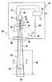
- FIG. 1is schematic view of a presentation imaging system in accordance with the preferred embodiment of the invention
- FIG. 2is a view taken along line 2 — 2 in FIG. 1 which illustrates the positioning of the sensor and observation axes of the imaging area.
- the current inventionprovides a presentation imaging system 10 used to identify objects, such as packages.
- the system 10is used to read machine readable information, such as bar codes, located on the surface of an object.
- the system 10is comprised of a processor 12 connected to a sensor 14 and an imaging device 16 .
- the imaging device 16receives images of objects located along an observation axis 54 .
- the imaging device 16is preferably an area scan camera, including an area array sensor, or another similar device.
- the sensor 14is preferably a proximity sensor or other similar device that can detect the presence and/or the distance of an object.
- the processor 12is coupled to the sensor 14 through a sensor connection 34 .
- the imaging device 16preferably has an attached lens 18 .
- the attached lens 18may be either a fixed focus or auto focus type which is driven by commands from the processor 12 , based on distance or position data received from the sensor 14 .
- the automatic focus lensmay be controlled by any combination of the sensor 14 , the imaging device 16 , and/or the processor 12 .
- the sensor 14is used only to detect the presence of the object.
- the imaging device 16is coupled to the processor 12 through a video connection 36 .
- the processor 12captures the images obtained from the imaging device 16 . Once the processor 12 captures the image, it processes the image looking for coded symbologies or other preprogrammed machine readable images or information.
- the processor 12may be capable of reading different bar code information. This bar code information may include, but not be limited to, UPC, EAN, Codabar, I205, Code 39, Code 128 and/or Code 93.
- the imaging device 16 and the processor 12may be capable of performing low, medium, or high density imaging as required by the information on the objects to be scanned.
- the imaging device 16 and the processor 12may be used for optical character recognition (OCR) or recognition of 2 d symbologies.
- OCRoptical character recognition
- the system 10has the capability of successfully imaging objects placed at a distance in excess of 5 feet from the housing opening 28 .
- a light source 20is connected to the processor 12 through a light source connection 46 .
- the light source 20is preferably a high intensity unit capable of providing a structured light beam 56 of sufficient lumens to an object placed at a distance from the imaging device 16 .
- Such light sourcesinclude, but are not limited to, halogen, xenon metal halide, or other lamp units.
- the light source 20has at least two modes of operation controlled by the processor 12 .
- the first modeprovides a low intensity illumination to clearly define an imaging area which can be easily recognized by material handlers, without a continuous high brightness that can obscure an operator's vision due to reflection from the package surface. This also allows for lower power consumption for the majority of the operating time for the system 10 .
- the light source 20brightly illuminates the object 44 placed in an imaging area 40 , which is generally co-extensive with the structured light 56 as shown in FIG. 2, allowing the camera 16 to image any machine readable information on the object 44 .
- the imagepasses through the lens 18 to the camera 16 , where it is converted to an image signal that is transmitted via cable 36 to the processor 12 , where it is processed looking for any preprogrammed machine readable information.
- a third modeis provided that gives a visual acknowledgment to the operator that the machine readable information on the object has been processed. This can be through having the light source 20 turn off or blink before returning to the first mode. Alternatively, other types of operator acknowledgment can be provided, such as an audio signal Additionally, different colors of lights may be used between settings to more clearly highlight the intensity settings used. Those skilled in the art will recognize that the number and intensity of the settings may be varied.
- a reflector 22is preferably used to allow light generated by the light source 20 to be reflected along the observational axis 54 , as shown in FIG. 1 .
- the reflector 22reflects light generated by the light source 20 through a preferred angle of 45° relative to the observation axis 54 in order to make the light from the light source 20 co-axial with the observation axis 54 .
- the positioning of the light source 20 and the reflector 22may be altered to provide differing configurations.
- the light source 20may be a point source or any other type of source, and the reflector 22 could be shaped to focus the light source to produce the structured beam 56 .
- the reflector 22is preferably a mirror, however, other embodiments may include other similar devices.
- the reflector 22has two openings 24 , 26 .
- a sensor opening 26is created to allow the sensor 14 to send and receive signals down a sensor sight line 52 .
- an imaging device opening 24is provided to allow the imaging device 16 to obtain images through the reflector 22 .
- the cut-outs 24 and 26may be of any size and geometry.
- a housing 30is provided to allow the components described above to be securely housed.
- the presentation imaging system 10is attached to a structural member in an overhead position allowing an unimpeded package imaging view.
- a housing window or opening 28allows the sensor sight line 52 , the imaging device field of view along the observation axis 54 , as well as the structured light beam 56 to exit the housing 30 .
- the presentation imaging system 10is shown imaging an object 44 .
- the object 44is moved into a position within the imaging area 40 which can be easily recognized by the user based on the structured beam 56 from the light source 20 illuminating the object 44 .
- the sensor 14detects the distance to the surface of the object 44 along the sensor sight line 52 , preferably using a signal reflected back from the surface of the object 44 when the object moves into the sight line 52 .
- the sight line 52 and the observation axis 54are in close proximity or nearly co-incident within the scan range 38 .
- other configurationsare possible including providing additional sensors to cover additional sections of the imaging area.
- the imaging area 40 of the imaging system 10may be altered based upon the needs of the user and the configuration of the imaging device, but is preferably coaxial and generally co-extensive with the structured light beam 56 , as shown in FIG. 2 .
- the sensor 14transmits distance data to the processor 12 .
- the processor 12processes the data, provides focus information to the lens 18 of the camera 16 , and intensifies the light source 20 to allow sufficient illumination of the object 44 for imaging.
- a feed back loopcan also be programmed for distance data from the sensor 14 and the camera focusing to ensure that focusing is completed prior to imaging.
- the imaging device 16is then activated by the processor 12 . Reflected light from the surface of the object 44 is gathered by the imaging device 16 focused through the lens 18 .
- the imaging device 16then transmits the image data to the processor 12 .
- the processor 12processes the transmitted image and analyzes the data against preprogrammed processing requirements.
- the processor 12will provide the data to a predetermined destination, such as a host computer system, and will provide notification that a successful scan has been accomplished.
- a predetermined destinationsuch as a host computer system
- this notificationmay include, but not be limited to, an audible alarm, winking the light source 20 off and on, changing the color of the light source 20 or other means.
Landscapes
- Physics & Mathematics (AREA)
- Electromagnetism (AREA)
- Engineering & Computer Science (AREA)
- Health & Medical Sciences (AREA)
- General Health & Medical Sciences (AREA)
- Toxicology (AREA)
- Artificial Intelligence (AREA)
- Computer Vision & Pattern Recognition (AREA)
- General Physics & Mathematics (AREA)
- Theoretical Computer Science (AREA)
- Image Input (AREA)
Abstract
Description
Claims (12)
Priority Applications (2)
| Application Number | Priority Date | Filing Date | Title |
|---|---|---|---|
| US10/104,750US6637893B2 (en) | 2002-03-22 | 2002-03-22 | Presentation imaging system |
| US10/695,175US6805449B2 (en) | 2002-03-22 | 2003-10-28 | Presentation imaging system |
Applications Claiming Priority (1)
| Application Number | Priority Date | Filing Date | Title |
|---|---|---|---|
| US10/104,750US6637893B2 (en) | 2002-03-22 | 2002-03-22 | Presentation imaging system |
Related Child Applications (1)
| Application Number | Title | Priority Date | Filing Date |
|---|---|---|---|
| US10/695,175Continuation-In-PartUS6805449B2 (en) | 2002-03-22 | 2003-10-28 | Presentation imaging system |
Publications (2)
| Publication Number | Publication Date |
|---|---|
| US20030179350A1 US20030179350A1 (en) | 2003-09-25 |
| US6637893B2true US6637893B2 (en) | 2003-10-28 |
Family
ID=28040684
Family Applications (1)
| Application Number | Title | Priority Date | Filing Date |
|---|---|---|---|
| US10/104,750Expired - LifetimeUS6637893B2 (en) | 2002-03-22 | 2002-03-22 | Presentation imaging system |
Country Status (1)
| Country | Link |
|---|---|
| US (1) | US6637893B2 (en) |
Cited By (9)
| Publication number | Priority date | Publication date | Assignee | Title |
|---|---|---|---|---|
| US20040004125A1 (en)* | 1998-07-10 | 2004-01-08 | Welch Allyn Data Collection, Inc. | Method and apparatus for extending operating range of bar code scanner |
| US20040085521A1 (en)* | 2002-03-22 | 2004-05-06 | Accu-Sort Systems, Inc. | Presentation imaging system |
| US20050110958A1 (en)* | 2003-11-21 | 2005-05-26 | Howell Schwartz | System and method for managing projector bulb life |
| US20060092383A1 (en)* | 2004-11-01 | 2006-05-04 | Gregory Vinson | System and method for projector external hazard proximity protection |
| US20080023556A1 (en)* | 2006-07-31 | 2008-01-31 | Igor Vinogradov | Imaging reader with target proximity sensor |
| US8281621B2 (en) | 2010-09-27 | 2012-10-09 | Whirlpool Corporation | Apparatus and method for determining a characteristic of a consumable |
| US8393548B2 (en) | 2010-09-27 | 2013-03-12 | Whirlpool Corporation | Removable component for a consumable with identifying graphic |
| US8400638B2 (en) | 2010-09-27 | 2013-03-19 | Whirlpool Corporation | Apparatus and method for determining a characteristic of a consumable |
| US9035785B2 (en) | 2010-09-27 | 2015-05-19 | Whirlpool Corporation | Graphic for use in determining a characteristic of a consumable |
Families Citing this family (6)
| Publication number | Priority date | Publication date | Assignee | Title |
|---|---|---|---|---|
| TW472169B (en)* | 2001-02-06 | 2002-01-11 | Avermedia Tech Inc | Object projection device capable of demarcating the projecting position |
| GB201309869D0 (en) | 2013-06-03 | 2013-07-17 | Ocado Ltd | Head-mounted code scanner |
| JP6637331B2 (en)* | 2016-02-22 | 2020-01-29 | 株式会社キーエンス | Safety scanner and optical safety system |
| JP2017150857A (en)* | 2016-02-22 | 2017-08-31 | 株式会社キーエンス | Safety scanner |
| JP6851137B2 (en)* | 2016-02-22 | 2021-03-31 | 株式会社キーエンス | Safety scanner |
| JP6736307B2 (en)* | 2016-02-22 | 2020-08-05 | 株式会社キーエンス | Safety scanner, optical safety system and configuration support device for safety scanner |
Citations (11)
| Publication number | Priority date | Publication date | Assignee | Title |
|---|---|---|---|---|
| US3774014A (en)* | 1972-03-20 | 1973-11-20 | Pitney Bowes Alpex | Printed code scanning system |
| US5028771A (en)* | 1989-02-28 | 1991-07-02 | Goldstar Co., Ltd. | Bar code reader |
| US5380992A (en)* | 1989-07-10 | 1995-01-10 | Koninklijke Ptt Nederland B.V. | Bar code detection using background-correlated bar criterion for ascertaining the presence of a bar |
| US5679941A (en)* | 1994-05-30 | 1997-10-21 | Kabushiki Kaisha Tec | Checkout device |
| US5900611A (en)* | 1997-06-30 | 1999-05-04 | Accu-Sort Systems, Inc. | Laser scanner with integral distance measurement system |
| US5984186A (en) | 1997-10-29 | 1999-11-16 | Psc Inc. | CCD-base bar code scanner |
| US6010070A (en)* | 1997-06-16 | 2000-01-04 | Nippon Electric Industry Co., Ltd. | Code reading device and method with variable light signal storage time |
| US6065839A (en)* | 1997-10-16 | 2000-05-23 | Elmo Co., Ltd. | Material exhibiting apparatus |
| US6065678A (en) | 1996-01-25 | 2000-05-23 | Symbol Technologies, Inc. | Bar code scanner having a focusing system |
| US6344874B1 (en)* | 1996-12-24 | 2002-02-05 | International Business Machines Corporation | Imaging system using a data transmitting light source for subject illumination |
| US20020067422A1 (en)* | 2000-10-11 | 2002-06-06 | Tsuyoshi Miura | Image monitor apparatus controlling camera and illumination in order to optimize luminance of picked-up image |
- 2002
- 2002-03-22USUS10/104,750patent/US6637893B2/ennot_activeExpired - Lifetime
Patent Citations (11)
| Publication number | Priority date | Publication date | Assignee | Title |
|---|---|---|---|---|
| US3774014A (en)* | 1972-03-20 | 1973-11-20 | Pitney Bowes Alpex | Printed code scanning system |
| US5028771A (en)* | 1989-02-28 | 1991-07-02 | Goldstar Co., Ltd. | Bar code reader |
| US5380992A (en)* | 1989-07-10 | 1995-01-10 | Koninklijke Ptt Nederland B.V. | Bar code detection using background-correlated bar criterion for ascertaining the presence of a bar |
| US5679941A (en)* | 1994-05-30 | 1997-10-21 | Kabushiki Kaisha Tec | Checkout device |
| US6065678A (en) | 1996-01-25 | 2000-05-23 | Symbol Technologies, Inc. | Bar code scanner having a focusing system |
| US6344874B1 (en)* | 1996-12-24 | 2002-02-05 | International Business Machines Corporation | Imaging system using a data transmitting light source for subject illumination |
| US6010070A (en)* | 1997-06-16 | 2000-01-04 | Nippon Electric Industry Co., Ltd. | Code reading device and method with variable light signal storage time |
| US5900611A (en)* | 1997-06-30 | 1999-05-04 | Accu-Sort Systems, Inc. | Laser scanner with integral distance measurement system |
| US6065839A (en)* | 1997-10-16 | 2000-05-23 | Elmo Co., Ltd. | Material exhibiting apparatus |
| US5984186A (en) | 1997-10-29 | 1999-11-16 | Psc Inc. | CCD-base bar code scanner |
| US20020067422A1 (en)* | 2000-10-11 | 2002-06-06 | Tsuyoshi Miura | Image monitor apparatus controlling camera and illumination in order to optimize luminance of picked-up image |
Cited By (20)
| Publication number | Priority date | Publication date | Assignee | Title |
|---|---|---|---|---|
| US20040004125A1 (en)* | 1998-07-10 | 2004-01-08 | Welch Allyn Data Collection, Inc. | Method and apparatus for extending operating range of bar code scanner |
| US6969003B2 (en) | 1998-07-10 | 2005-11-29 | Welch Allyn Data Collection, Inc. | Method and apparatus for extending operating range of bar code scanner |
| US20040085521A1 (en)* | 2002-03-22 | 2004-05-06 | Accu-Sort Systems, Inc. | Presentation imaging system |
| US6805449B2 (en)* | 2002-03-22 | 2004-10-19 | Accu-Sort Systems, Inc. | Presentation imaging system |
| US20050110958A1 (en)* | 2003-11-21 | 2005-05-26 | Howell Schwartz | System and method for managing projector bulb life |
| US7055962B2 (en)* | 2003-11-21 | 2006-06-06 | Dell Products L.P. | System and method for managing projector bulb life |
| US20060170882A1 (en)* | 2003-11-21 | 2006-08-03 | Howell Schwartz | System and method for managing projector bulb life |
| US7156525B2 (en)* | 2003-11-21 | 2007-01-02 | Dell Products L.P. | System and method for managing projector bulb life |
| US20060092383A1 (en)* | 2004-11-01 | 2006-05-04 | Gregory Vinson | System and method for projector external hazard proximity protection |
| US7210791B2 (en)* | 2004-11-01 | 2007-05-01 | Dell Products L.P. | System and method for projector external hazard proximity protection |
| US20080023556A1 (en)* | 2006-07-31 | 2008-01-31 | Igor Vinogradov | Imaging reader with target proximity sensor |
| US7597263B2 (en)* | 2006-07-31 | 2009-10-06 | Symbol Technologies, Inc. | Imaging reader with target proximity sensor |
| US8281621B2 (en) | 2010-09-27 | 2012-10-09 | Whirlpool Corporation | Apparatus and method for determining a characteristic of a consumable |
| US8393548B2 (en) | 2010-09-27 | 2013-03-12 | Whirlpool Corporation | Removable component for a consumable with identifying graphic |
| US8400638B2 (en) | 2010-09-27 | 2013-03-19 | Whirlpool Corporation | Apparatus and method for determining a characteristic of a consumable |
| US8628024B2 (en) | 2010-09-27 | 2014-01-14 | Whirlpool Corporation | Removable component for a consumable with identifying graphic |
| US8780353B2 (en) | 2010-09-27 | 2014-07-15 | Whirlpool Corporation | Apparatus and method for determining a characteristic of a consumable |
| US8800084B2 (en) | 2010-09-27 | 2014-08-12 | Whirlpool Corporation | Method for determining a characteristic of a consumable |
| US8967489B2 (en) | 2010-09-27 | 2015-03-03 | Whirlpool Corporation | Removable component for a consumable with identifying graphic |
| US9035785B2 (en) | 2010-09-27 | 2015-05-19 | Whirlpool Corporation | Graphic for use in determining a characteristic of a consumable |
Also Published As
| Publication number | Publication date |
|---|---|
| US20030179350A1 (en) | 2003-09-25 |
Similar Documents
| Publication | Publication Date | Title |
|---|---|---|
| US9569652B2 (en) | Code symbol reading system | |
| US6637893B2 (en) | Presentation imaging system | |
| CN101551848B (en) | Handheld Imaging-Based Barcode Symbol Reader Supporting Narrow-Area and Wide-Area Mode Illumination and Image Capture | |
| EP1281271B1 (en) | Coplanar camera scanning system | |
| US8004604B2 (en) | Coplanar camera scanning system | |
| US8910872B2 (en) | Imaging reader and method with dual function illumination light assembly | |
| US20100096460A1 (en) | Hybrid laser scanning and imaging reader | |
| US7543754B2 (en) | Methods and apparatus for information capture illumination | |
| US20100320272A1 (en) | Hybrid laser scanning and imaging reader | |
| US9135477B2 (en) | Radio frequency identification reader with illuminated field of view | |
| US8618468B2 (en) | Imaging module with folded illuminating and imaging paths | |
| EP2401698B1 (en) | Compact imaging engine for imaging reader | |
| US8840027B2 (en) | Electro-optical reader with enhanced laser light pattern visibility | |
| JPH02183879A (en) | barcode reader | |
| US20090140049A1 (en) | Stray light reduction in imaging reader | |
| EP1844423A2 (en) | Asymmetrical scanner | |
| US8950676B2 (en) | Image capture based on working distance range restriction in imaging reader | |
| US20070164112A1 (en) | Method and system for facilitating aiming of a machine-readable symbol reader, such as barcode reader | |
| US20030201327A1 (en) | Variable focal length imaging device | |
| US6805449B2 (en) | Presentation imaging system | |
| US20240211710A1 (en) | Methods and systems for operating object detection-based indicia scanner | |
| JP3810154B2 (en) | Optical symbol reader |
Legal Events
| Date | Code | Title | Description |
|---|---|---|---|
| AS | Assignment | Owner name:ACCU-SORT SYSTEMS, INC., PENNSYLVANIA Free format text:ASSIGNMENT OF ASSIGNORS INTEREST;ASSIGNOR:HECHT, KURT;REEL/FRAME:012726/0655 Effective date:20020322 | |
| AS | Assignment | Owner name:UNION NATIONAL BANK AND TRUST COMPANY OF SOUDERTON Free format text:SECURITY INTEREST;ASSIGNOR:ACCU-SORT SYSTEMS, INC.;REEL/FRAME:013333/0727 Effective date:20020627 | |
| STCF | Information on status: patent grant | Free format text:PATENTED CASE | |
| FPAY | Fee payment | Year of fee payment:4 | |
| FPAY | Fee payment | Year of fee payment:8 | |
| AS | Assignment | Owner name:ACCU-SORT SYSTEMS, INC., PENNSYLVANIA Free format text:RELEASE BY SECURED PARTY;ASSIGNOR:UNIVEST NATIONAL BANK AND TRUST COMPANY (FKA UNION NATIONAL BANK AND TRUST COMPANY OF SOUDERTON);REEL/FRAME:027206/0742 Effective date:20111005 | |
| FPAY | Fee payment | Year of fee payment:12 | |
| AS | Assignment | Owner name:DATALOGIC AUTOMATION, INC., PENNSYLVANIA Free format text:MERGER AND CHANGE OF NAME;ASSIGNORS:DATALOGIC AUTOMATION, INC.;ACCU-SORT SYSTEMS, INC.;REEL/FRAME:036327/0443 Effective date:20120701 | |
| AS | Assignment | Owner name:DATALOGIC USA, INC., OREGON Free format text:MERGER;ASSIGNORS:DATALOGIC ADC, INC.;DATALOGIC AUTOMATION, INC.;REEL/FRAME:067878/0571 Effective date:20161213 |