US6637882B1 - Eye viewing device for retinal viewing through undilated pupil - Google Patents
Eye viewing device for retinal viewing through undilated pupilDownload PDFInfo
- Publication number
- US6637882B1 US6637882B1US09/783,481US78348101AUS6637882B1US 6637882 B1US6637882 B1US 6637882B1US 78348101 AUS78348101 AUS 78348101AUS 6637882 B1US6637882 B1US 6637882B1
- Authority
- US
- United States
- Prior art keywords
- light
- air
- viewing
- lens
- eye
- Prior art date
- Legal status (The legal status is an assumption and is not a legal conclusion. Google has not performed a legal analysis and makes no representation as to the accuracy of the status listed.)
- Expired - Lifetime, expires
Links
- 210000001747pupilAnatomy0.000titleclaimsabstractdescription53
- 230000002207retinal effectEffects0.000titleclaimsabstractdescription26
- 238000005286illuminationMethods0.000claimsabstractdescription81
- 230000004313glareEffects0.000claimsabstractdescription35
- 238000003384imaging methodMethods0.000claimsdescription77
- 230000003287optical effectEffects0.000claimsdescription27
- 210000001525retinaAnatomy0.000claimsdescription27
- 210000004087corneaAnatomy0.000claimsdescription14
- 239000000463materialSubstances0.000claimsdescription14
- NIXOWILDQLNWCW-UHFFFAOYSA-Nacrylic acid groupChemical groupC(C=C)(=O)ONIXOWILDQLNWCW-UHFFFAOYSA-N0.000claimsdescription12
- PPBRXRYQALVLMV-UHFFFAOYSA-NStyreneChemical compoundC=CC1=CC=CC=C1PPBRXRYQALVLMV-UHFFFAOYSA-N0.000claimsdescription6
- 239000011521glassSubstances0.000claimsdescription6
- 230000004256retinal imageEffects0.000abstractdescription29
- 210000001508eyeAnatomy0.000description103
- 238000010586diagramMethods0.000description18
- 238000004891communicationMethods0.000description15
- 210000000554irisAnatomy0.000description6
- 210000003786scleraAnatomy0.000description6
- 230000013011matingEffects0.000description4
- 238000004513sizingMethods0.000description4
- 230000010344pupil dilationEffects0.000description3
- 206010027646MiosisDiseases0.000description2
- 230000005540biological transmissionEffects0.000description2
- 230000003902lesionEffects0.000description2
- 239000002184metalSubstances0.000description2
- 238000000034methodMethods0.000description2
- 230000008569processEffects0.000description2
- 238000007493shaping processMethods0.000description2
- 208000002177CataractDiseases0.000description1
- 208000028006Corneal injuryDiseases0.000description1
- 208000006550MydriasisDiseases0.000description1
- 206010028980NeoplasmDiseases0.000description1
- 210000001367arteryAnatomy0.000description1
- 230000004323axial lengthEffects0.000description1
- 230000009286beneficial effectEffects0.000description1
- 230000015572biosynthetic processEffects0.000description1
- 230000000903blocking effectEffects0.000description1
- 230000008859changeEffects0.000description1
- 238000000701chemical imagingMethods0.000description1
- 239000011248coating agentSubstances0.000description1
- 238000000576coating methodMethods0.000description1
- 230000000295complement effectEffects0.000description1
- 238000003745diagnosisMethods0.000description1
- 230000002497edematous effectEffects0.000description1
- 230000000694effectsEffects0.000description1
- 238000005516engineering processMethods0.000description1
- 230000002708enhancing effectEffects0.000description1
- 239000000835fiberSubstances0.000description1
- 238000001914filtrationMethods0.000description1
- 239000005357flat glassSubstances0.000description1
- 238000004519manufacturing processMethods0.000description1
- 230000007246mechanismEffects0.000description1
- 239000000203mixtureSubstances0.000description1
- 239000002991molded plasticSubstances0.000description1
- 210000004126nerve fiberAnatomy0.000description1
- 238000005457optimizationMethods0.000description1
- 238000004806packaging method and processMethods0.000description1
- 230000002093peripheral effectEffects0.000description1
- 230000009467reductionEffects0.000description1
- 230000011514reflexEffects0.000description1
- 239000007787solidSubstances0.000description1
- 230000003595spectral effectEffects0.000description1
- 238000001228spectrumMethods0.000description1
- 239000000758substrateSubstances0.000description1
- 210000003462veinAnatomy0.000description1
Images


Classifications
- A—HUMAN NECESSITIES
- A61—MEDICAL OR VETERINARY SCIENCE; HYGIENE
- A61B—DIAGNOSIS; SURGERY; IDENTIFICATION
- A61B3/00—Apparatus for testing the eyes; Instruments for examining the eyes
- A61B3/10—Objective types, i.e. instruments for examining the eyes independent of the patients' perceptions or reactions
- A61B3/14—Arrangements specially adapted for eye photography
- A61B3/15—Arrangements specially adapted for eye photography with means for aligning, spacing or blocking spurious reflection ; with means for relaxing
- A61B3/156—Arrangements specially adapted for eye photography with means for aligning, spacing or blocking spurious reflection ; with means for relaxing for blocking
- A61B3/158—Arrangements specially adapted for eye photography with means for aligning, spacing or blocking spurious reflection ; with means for relaxing for blocking of corneal reflection
- A—HUMAN NECESSITIES
- A61—MEDICAL OR VETERINARY SCIENCE; HYGIENE
- A61B—DIAGNOSIS; SURGERY; IDENTIFICATION
- A61B3/00—Apparatus for testing the eyes; Instruments for examining the eyes
- A61B3/10—Objective types, i.e. instruments for examining the eyes independent of the patients' perceptions or reactions
- A61B3/14—Arrangements specially adapted for eye photography
- A61B3/15—Arrangements specially adapted for eye photography with means for aligning, spacing or blocking spurious reflection ; with means for relaxing
- A61B3/156—Arrangements specially adapted for eye photography with means for aligning, spacing or blocking spurious reflection ; with means for relaxing for blocking
Definitions
- This inventionrelates generally to medical diagnostic instruments, and specifically to an eye viewing device for use in retinal viewing.
- a beam splitteris provided in the optical viewing path which directs illumination light rays into an eye, and simultaneously allows receive imaging light rays to pass therethrough.
- the substantial light losses inherent with this designrequire that a large, high powered light source be incorporated in the device for the device to satisfactorily illuminate a retina.
- High powered light sourcesin general, are difficult to package, consume excessive amounts of electrical input power, and produce large amounts of heat and unwanted light such as glare.
- High powered light sourcesalso have large filaments, typically larger than the diameter of an undilated pupil. This makes indirect ophthalmoscopes especially susceptible to glare problems attributable to incident light rays being reflected from outer eye structures such as the iris, cornea and sclera.
- retinal viewing camerasfor use in retinal viewing, such as fundus cameras, provide high quality imaging.
- retinal viewing camerasin general, are expensive, typically require pupil dilation for retinal viewing, and typically require operation by a highly skilled and trained camera operator.
- the present inventionis a low input power, low cost eye viewing device for use in viewing a retina.
- the deviceprovides wide field retinal viewing without pupil dilation.
- an eye viewing deviceincludes a converging light illumination system adapted to generate light rays which, when the device is in an operative position, converge at about a pupil of a patient and diverge inside an eye to illuminate a wide retinal field.
- the converging light illumination systemprovides illumination of a wide retinal field through a small pupil which may be in an undilated state.
- the converging light illumination systemalso reduces electrical input power consumption and reduces glare, as substantially all light delivered by the illumination system enters an eye through a patient's pupil without being reflected from an eye structure outside of a pupil opening such as the iris and sclera.
- an eye viewing device of the inventionincludes a viewing system having an aperture stop positioned substantially conjugate to a patient's pupil and substantially coaxial with an imaging axis of the viewing system.
- An aperture stop positioned substantially conjugate to a patient's pupil and substantially coaxial with an imaging axisoperates to admit light that forms a retinal image and to block light that does not form the retinal image.
- the aperture stopoperates to block unwanted light both when the device is positioned forward of an operative position and when the device is in an operative position.
- the aperture stopthereby reduces glare and improves image quality both during entry of the device into an eye (when the device is being maneuvered into an operative position) and during retinal viewing (when the device is in an operative position).
- the eye viewing deviceis made especially well suited for retinal viewing through an undilated eye by sizing the aperture of the aperture stop in accordance with the diameter of a pupil of an undilated eye.
- the aperture stopoperates to block substantially all light reflected from eye structures outside the diameter of a pupil (such as the iris and sclera).
- FIG. 1Ais a functional schematic diagram of an eye viewing device of the invention showing illumination light rays for illustrating operation of an illumination system according to the invention
- FIG. 1Bis a functional schematic diagram of an eye viewing device of the invention showing receive optical light rays which illustrate operation of the device's imaging system;
- FIG. 1Cis a functional schematic diagram of an eye viewing device of the invention showing incident illumination light rays when the device is at a distance away from an operative position;
- FIG. 1Dis a functional schematic diagram of the eye viewing device of FIG. 1C showing receive optical light rays when the device is at a distance away from an operative position;
- FIG. 1Eis a functional diagram of an eye viewing device of the invention showing incident light rays reflected from an objective lens
- FIG. 2Ais a functional schematic diagram showing incident light rays of an illumination system which may be incorporated in the invention
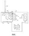
- FIG. 2Bis a schematic diagram illustrating a specific embodiment of the invention.
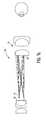
- FIG. 2Cis an exploded view of a section of the specific embodiment shown in FIG. 2 A.
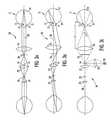
- FIG. 3Ais a functional schematic diagram of an embodiment of the invention showing light rays from an on-axis object illustrating operation of an embodiment of an imaging system according to the invention having a defocused mirror;
- FIG. 3Bis a functional schematic diagram of an embodiment of the invention showing light rays from an off-axis object illustrating operation of an imaging system according to the invention having a defocused mirror;
- FIG. 3Cis a functional schematic diagram of an embodiment of the invention showing illumination light rays which illustrate operation of an illumination system having an on-axis light source;
- FIG. 4is a functional schematic diagram of another embodiment of the invention having a defocused light source
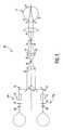
- FIG. 5is functional schematic diagram of the invention configured for binocular viewing
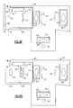
- FIGS. 6A-6Kare physical schematic diagrams illustrating various features which may be incorporated in certain specific embodiments of the invention.
- Eye viewing device 10includes an illumination system, the operation of which is described mainly with reference to FIG. 1A, and an imaging system, the operation of which is described mainly with reference to FIG. 1 B.
- the device of FIGS. 1A-1Eis especially well suited for use in viewing a retina through an undilated pupil.
- Small diameter undilated pupilspresent numerous challenges to viewing retinal images. Small diameter undilated pupils tend to inhibit the transmission of both incident light directed toward a retina and reflected light corresponding to a retinal image. Furthermore, light that is directed into a pupil and that is blocked from entry into a pupil by highly reflective surfaces of outer eye structures such as the iris and sclera tends to be reflected into a viewing system as glare.
- the device of FIGS. 1A-1Eincludes features which operate in combination to overcome the numerous challenges to viewing a retinal image through an undilated pupil. In one aspect, the device of FIGS.
- 1A-1Eincludes the combination of a converging light source illumination system and an aperture stop.
- the converging light source illumination systemoperates to direct a substantial amount of light through a small diameter opening while the aperture stop operates to block glare attributable to light rays being reflected from outer eye structures.
- the illumination systemoperates to generate illumination light rays which converge at an apex 34 and diverge thereafter.
- An eye viewing device having a converging light ray illumination systemis positioned in an operative position relative to a patient when substantially a maximum amount of incident light enters eye 11 through pupil 12 .
- an operative positionis achieved when apex 34 of the cone of light generated by the illumination system is positioned at about a pupil 12 of a patient.
- a converging light ray illumination systemcan be provided by the combination of a light source 14 and objective lens 16 positioned forward of the light source 14 for converging light rays emanating from source 14 .
- a converging light source illumination systemWith a converging light source illumination system, a much higher percentage of incident light rays enter pupil 12 to illuminate retina 19 than are reflected off outer eye structures 17 and 21 . Because there is little wasted incident light, a converging light ray illumination system reduces the electrical input power consumption of the illumination system. Because a relatively smaller amount of incident light reflects off outer eye structures such as iris 17 and sclera 21 , there is less unwanted light received by the imaging system.
- Light source 14can be a light generating light source, such as a filament-based lamp, an arc lamp, a fiber optic light source or a solid state light source.
- a preferred light source for the eye viewing deviceis the light source described with reference to FIG. 2 A.
- light source 14is provided by a reflective element such as a mirror, which operates in association with a light-generating light source 18 , such as a lamp, and a condenser lens 20 which converges light from light source 18 onto mirror 14 .
- the imaging system of the deviceincludes objective lens 16 , imaging lens 22 , and an eyepiece lens 24 .
- a retinal image focal plane 26is produced intermediate objective lens 16 and imaging lens 22
- an eyepiece focal plane 28is produced intermediate imaging lens 22 and eyepiece lens 24 .
- the imaging systemfurther includes an imaging axis 30 on which lenses 16 , 22 , and 24 are substantially centered.
- the term “lens”can refer to a single optical element or a plurality of optical elements functioning together, while an operative position has been defined herein as the position at which substantially a maximum amount of incident light rays enter eye 11 through pupil 12 .
- An operative positioncan also be defined as the position at which a patient's pupil is conjugate to aperture stop 32 .
- the retinal image light rays crossing retinal focal plane 26consist of light rays that enter eye 11 through pupil 12 and which are reflected from retina 19 through pupil 12 . Since small undilated pupils tend to inhibit the transmission of both incident light into an eye and reflected retinal image light out of the eye, retinal images viewed through undilated pupils are readily obscured by glare (which is especially prevalent when retinas are viewed through undilated pupils since incident light is more likely to be reflected from highly reflective outer eye structures).
- retinal imagescan be obscured by glare attributable to other sources such as light that is reflected from a patient's cornea (corneal glare) and light that is reflected from a component of the eye viewing device such as a lens of the device (internal glare).
- device 10preferably includes features which operate to reduce such glare, and in so doing reduce the percentage of received light rays not corresponding to a retinal image relative to the percentage of received light rays corresponding to a retinal image.
- One feature which operates to reduce the percentage of light rays not corresponding to the retinal imageis the feature of converging light illumination, described above.
- a converging light illumination systema relatively high percentage of light enters eye 11 through pupil 12 , and a relatively low percentage of light is reflected from outer eye structures 17 and 21 as seen in FIG. 1 A.
- Other features which may be incorporated to increase the percentage of retinal image forming received light relative to unwanted lightare described hereinbelow.
- an aperture stop 32is positioned forward of imaging lens 22 to block unwanted light.
- Aperture stop 32should be positioned substantially coaxially with imaging axis 30 and substantially conjugate to a patient's pupil 12 when in an operative position in relation to device 10 .
- Positioning of aperture stop 32 substantially coaxial with imaging axis 30encourages substantially a maximum amount of useful receive imaging light to be admitted through imaging lens 22 without also admitting glare light that originates radially outside the patient's pupil 12 .
- aperture stop 32By positioning aperture stop 32 so that it is substantially conjugate to a pupil, aperture stop 32 operates to block light reflected from outer eye structures 17 and 21 .
- the preferred position of aperture stop 32 in a device made in accordance with FIGS. 1A-1Ecan be described as one that is substantially conjugate to the apex of the cone of light generated by the illumination system.
- aperture 33 of aperture stop 32should be sized in accordance with the diameter of the pupil through which a retina is viewed.
- the diameter of an undilated pupilis about 2 mm.
- aperture 33should be sized to correspond to a patient pupil diameter of about 2 mm.
- the resulting diameter of aperture 33is determined by multiplying the pupil diameter by the magnification of the pupil in the plane of the aperture stop 32 . This same principle can be applied to optimize the instrument design for other pupil sizes, larger and smaller.
- FIGS. 1C and 1Dillustrate illumination light rays exiting the device and reflecting off the eye as they are received in a viewing system of device 10 during entry of the device into an eye (during the process of moving the device into an operative position).
- FIG. 1Cillustrates incident light rays generated by device 10 when the device is at a distance away from an operative position
- FIG. 1Dillustrates received reflected light rays of a device positioned at the same distance away from an operative position as is shown in FIG. 1 C.
- light source 14may be positioned just forward of aperture stop 32 outside of the boundary between received and blocked light and off-axis with respect to imaging axis 30 of device 10 . Positioning light source forward of aperture stop 32 , outside of the boundary between received and blocked light defined by aperture 33 , assures that light source 14 has no obscuring effect on the viewed image and assures maximum image brightness in the user's eye. Positioning light source 14 off-axis also reduces both internal and corneal glare. By positioning light source off-axis, incident light that is reflected off of lens 16 or off of cornea 15 is directed at an angle with respect to axis 30 and, therefore, away from the optical receive path.
- Glaremay be further reduced by shaping the first surface 23 of objective lens 16 so that first surface 23 is curved and substantially concentric with the center of aperture 33 as seen by the embodiment of FIG. 1 E. This assures that light that is reflected from surface 23 is reflected to a point equal to and opposite light source 14 with respect to imaging axis 30 . If light source 14 is positioned outside of the boundary dividing blocked and received light defined by aperture 33 , the concentric curved first surface 23 assures that internal glare resulting from light being reflected from surface 23 is blocked by aperture stop 32 .
- glarecan be reduced by disposing linear polarizers in the imaging and illumination paths in a crossed configuration.
- FIG. 2 BA specific embodiment of an eye viewing device described generally with reference to FIGS. 1A-2A is described with reference to the physical layout diagram of FIG. 2 B. This embodiment is advantageous compared to that in FIG. 2A because fewer number of lenses are used and because the non-eyepiece lenses are made from inexpensive molded plastic.
- the surfaces of the various elements of the illumination system of the eye viewing device of FIG. 2Bare numbered surfaces 100 through 113 . The elements containing these surfaces are briefly described hereinbelow.
- lamp filament 102provides the source of illumination for the illumination system.
- light source 102preferably comprises a filament having a length of about 0.025 to 0.030 inches, a diameter of between about 0.0123 and 0.0136 inches, a number of turns of between 6.5 to 7.5, and a power rating of between approximately 3.25 and 3.33 watts.
- Lamp filament 102is preferably oriented horizontally and rotated about 90° from the viewing axis.
- Device 10may have an aperture window 104 that lies in plane X.
- the aperture windowshould be formed at a position that is conjugate to a patient's retina.
- a smaller apertureprovides easier view of a patient's retina through small pupils and cataracts.
- a larger aperturemay be used for dilated pupils and for general examination of the central and peripheral retina.
- Device 10further includes an aperture wheel 106 comprising a plurality of optical elements which may be rotated into a position forward of filament 102 in the illumination optical path.
- Aperture wheel 106may carry an apertured glass 108 .
- Apertured glass 108may comprise plate glass having a lithography-formed slit or a machined slit in a metal substrate. The slit is helpful in determining various levels of retinal lesions, particularly tumors and edematous optic discs.
- Apertured glass 108may further comprise light filtering material.
- apertured glass 108filters red light and blue light.
- the red-free filterexcludes red retinal rays for easy identification of veins, arteries, and nerve fibers.
- the blue filteris used in conjunction with fourescein drops applied to the eye to detect corneal abrasions and other anterior and posterior segment lesions. Spacing apertured glass 108 a distance away from plane X minimizes the imaging of surface imperfections onto a retina.
- the illumination system shown in FIG. 2Bfurther includes wide band hot mirror 110 which limits infrared and UV energy from entering a patient's eye.
- the illumination systemincludes con denser lens 20 , which as described previously collects light from filament 102 and operates in combination with objective lens 16 to project an image of filament 102 onto or near a patient's cornea.
- the illumination system shown in FIG. 2Bfurther includes linear polarizer 112 .
- linear polarizer 112operates in combination with linear polarizer 202 of the imaging system to reduce corneal glare and glare that originates from the objective lens.
- light source 14is reflected by mirror 114 .
- the magnification of filament 102 onto mirror 114is about 1.5 in the embodiment shown.
- Mirror 114is mounted at an angle, ⁇ , of 3.8 degrees from imaging axis 30 relative to objective lens 16 .
- the orientation of the filamentmatches the geometric shape of the mirror, thus minimizing the mirror size.
- Objective lens 16operates in combination with condenser lens 20 to project an image of filament 102 onto a patient's cornea 15 .
- Objective lens 16 and cornea 15also form part of the imaging system.
- retinal image light rayspass through cornea 15 in a collimated formation.
- Objective lens 16focuses the parallel light from the patient's eye to a retinal image focal plane 26 between the objective lens and aperture stop 32 , FIG. 2 C.
- Aperture stop 32operates to block light that originates outside a 2 mm diameter circle located about 25 mm from the objective lens. This is the location of a patient's pupil when the instrument is in its nominal operating position.
- Linear polarizer 202operates in combination with linear polarizer 112 of the illumination system to reduce internal and external glare, especially internal glare from the objective lens and external glare attributable to corneal reflections.
- Linear polarizer 112 of the illumination system and linear polarizer 202 of the imaging systemare disposed in a cross-polarized configuration.
- Imaging lens 22 in the embodiment of FIG. 2Bincludes two lens elements, a first lens element 22 A and second lens element 22 B.
- the lens elements forming the imaging lensare separated by an air gap.
- Imaging lens 22images the retinal image focal plane 26 of the objective lens 16 to the eyepiece focal plane 28 .
- a field stop(not shown) sized to correspond to the field of view may be disposed at eye piece plane 28 .
- Retinal image focal plane 26 and eyepiece focal plane 28are conjugate to the patient's and viewer's retinas. Two internal image planes are required for proper orientation of the user's view of the patient's retina eyepiece lens 24 not labeled in FIG. 2 b.
- Eyepiece lens 24comprises two lens elements 24 A and 24 B.
- the eyepiece assembly in the embodiment of FIG. 2Bhas an approximately +/ ⁇ 18 diopter focusing range.
- An apparatus for use in moving eyepiece lens elements 24 A and 24 Bis described in commonly assigned application Ser. No. 09/774,726 (now issued as U.S. Pat. No. 6,390,625) entitled “Focusing Mechanism” filed concurrently herewith and incorporated herein by reference.
- All of the lenses of the illumination system and imaging system described herein aboveshould be coated with an anti-reflection coating.
- Table 1shows the value of the radius of curvature R (in mm), the on-axis surface spacing D (in mm), the aperture radius, AR, as well as the material associated with each optical surfaces of the specifically designed illumination system shown in FIG. 2 B.
- the six-digit numbers in the “materials” column of Table 1 and Table 3refer to military code material identifications.
- Table 2shows the coefficients characterizing the rotationally symmetric aspheric surfaces S 5 , S 6 , and S 12 of the specific illumination system shown in FIG. 2 B.
- Yis the radial distance from the optical axis
- Table 3shows the values of the radius of curvature R (in mm), the on-axis surface spacing d (in mm), the aperture radius, Ar, as well as the material composition associated with each optical surface of the specifically designed imaging system shown in FIG. 2 B.
- Table 4shows the coefficients characterizing the rotationally symmetric aspheric surfaces S 2 , S 7 , S 8 , and s 9 of the specific imaging system of FIG. 2A as defined by equation 1.
- Tables 1-4can be scaled up or down. Furthermore, while the dimensions designated in Tables 1-4 pertain to one preferred embodiment of the invention, it will be understood that the components of the eye viewing device may bear relationships to one another that deviate from those listed in Tables 1 to 4. In developing guidelines for the manufacture of alternative embodiments of the eye viewing device having the general configuration shown in FIGS. 1A-2B, the inventors have found that it is advantageous to maintain certain dimensions of the system and relationships between certain components of the system within certain ranges. Specifically, with respect to the embodiment shown in FIGS. 2B and 2C, relationships described hereinbelow apply.
- the inventorshave found it advantageous to maintain the focal length of the condenser lens 20 between about 8 mm and 15 mm, and to maintain the magnification of the filament onto mirror between about 1 and 2.
- internal glareis reduced by shaping the concave surface of objective lens 16 so that the concave surface is substantially centered about the center of aperture stop 32 .
- the inventorshave found the glare-reducing benefits of such a configuration are substantially yielded if the radius of the concave surface and the distance from the center of the aperture stop to the concave lens surface differ by approximately less than 10 percent.
- the inventorshave found that the focal length of the objective lens 16 should be maintained between about 15 mm and 25 mm and that the focal length of imaging lens 22 should be maintained between about 10 mm and 20 mm.
- imaging lens 22preferably operates in a reduction mode with a magnification of between about 0.5 and about 0.9.
- optical elements described with-reference to FIG. 2B hereinmay be housed in a housing such as a housing shown in one of the commonly assigned Design patent application Ser. Nos. 29/137,182, 29/137,172, and 29/137,181 all entitled “Eye Viewing Device” and are filed concurrently herewith and incorporated herein by reference.
- light source 14is disposed directly in the field of view in a highly defocused position in relation to focal planes 26 and 28 .
- light source 14By disposing light source 14 on imaging axis 30 , light source 14 provides for maximally efficient illumination of a retina 19 .
- Positioning the light source off-axis as is shown by light source 14 ′results in less-than-maximally efficient retinal illumination, but also reduces glare for reasons that have been discussed herein.
- Light source 14 in the embodiment of FIGS. 3A-3Cshould be positioned in a highly defocused position in relation to any image plane of the eye viewing device conjugate to a patient's retina 19 in an operative position in relation to device 10 .
- a highly defocused position for source 14 in relation to an image focal plane conjugate to a retinais provided by disposing source 14 intermediate retinal focal plane 26 and imaging lens 22 .
- source 14becomes less in focus at any plane conjugate to and including eyepiece focal plane 28 as the source is moved toward imaging lens 22 and away from retinal focal plane 26 .
- source 14is positioned as close as is physically possible to lens 22 .
- Corneal glarecan be reduced in the embodiment of FIGS. 3A-3C if source 14 is disposed in device 10 in a position that is conjugate to the surface of a cornea when the device is in an operative position in relation to a patient. If light source 14 is positioned conjugate to cornea 15 , many light rays which do happen to be reflected from cornea 15 are imaged directly onto light source 14 . If light source 14 is provided by a reflective element as shown, these light rays correspond to a cornea image and are blocked before reaching eyepiece focal plane 28 , thereby reducing corneal glare.
- the objective lens 16may be provided by a lens system having a focal length of about 25 mm, and a back focal length of about one-half the focal length.
- the eye viewing devicemay be configured so that the lens surface closest to the patient in the objective lens system is positioned about 25 mm from a patient's cornea when in an operative position.
- the objective lens systemaccepts parallel or nearly parallel light from a patient's eye and focuses the light to an internal image located at or near the back focal plane 26 of the objective.
- the objective lens systemmay have a diameter of about 25 mm.
- Imaging lens 22may be provided by a lens system having a focal length of about 25 mm, a back focal length of about 18 mm and a clear aperture of about 20 mm.
- the imaging lensmay project an internal image from the objective focal plane 26 to eyepiece focal plane 28 at a magnification of about 0.6 ⁇ .
- Eyepiece focal plane 28may have an aperture of about 8 mm in diameter, corresponding to the focal plane diameter of a typical 20 ⁇ eyepiece.
- the axial length from objective lens 16 to eyepiece focal plane 28may be about 90 to 100 mm.
- condenser lens 20may be provided by a condenser system having a numerical aperture of about 0.2 to 0.4, working at a magnification of about 1 ⁇ to 2 ⁇ , with a focal length of about 9 mm.
- aperture stop 32may be positioned substantially normal to axis 30 and approximately halfway between the most rearward point of light source 14 and the most forward point of imaging lens 22 .
- Aperture stop 32may have an aperture diameter of about 4.6 mm.
- FIG. 4An alternative optical configuration for the eye viewing device of FIGS. 3A-3C having a defocused light source is described with reference to FIG. 4 .
- light source 14is disposed forward of objective lens 16 and imaging lens 22 is deleted.
- Light source 14is disposed in a highly defocused position in relation to retinal focal plane 26 by disposing light source 14 in proximity with objective lens 16 .
- objective lens 16does not form part of the optical illumination system. Instead, illumination light rays which converge at a cornea 15 and diverge toward a retina 19 are formed by disposing condenser lens 20 in relationship with light source mirror 14 such that light rays reflected from the mirror converge after being reflected. Further with reference to the embodiment of FIG.
- eyepiece lens 24may optionally be removed and replaced with image sensor 52 , such as a CCD image sensor, which is positioned on retinal focal plane 26 .
- image sensor 52such as a CCD image sensor
- a processor systemin communication with sensor 52 , can be configured to capture image signals generated by sensor 52 , process such signals, and if desirable, electronically reverse or magnify any captured images to accomplish the function provided optically by imaging lens 22 of the eye viewing device of FIGS. 1A-3C.
- optical elementssuch as diffractive lenses, binary gratings, phase filters, holographic optical elements (HOE), gradient-index lenses, and hybrid optical elements.
- a binocular eye viewing devicetypically includes a collimating optical element 70 for collimating light rays of the imaging path, and separating optics 72 for splitting light rays transmitted by collimating optics 70 into two separate imaging paths 74 A and 74 B.
- Separating optics 72typically include a combination of such optical elements as prisms and/or mirrors.
- binocular eye viewing device 10 ′′may further include orientation optics 76 disposed in each binocular imaging path 74 A, 74 B for setting the orientation of images transmitted by separating optics as is necessary.
- Orientation optics 76may include such optical elements as prism and/or mirror optical elements.
- Binocular eye viewing device 10 ′′may further include decollimation optics 78 and eyepiece optics 80 disposed in each imaging path 74 A and 74 B.
- Each eyepiece optics 80collimates light so that images can be perceived by a viewer.
- the eye tubes (not shown) of eyepiece optics 80may be arranged in an orientation slightly diverging toward a viewer's eyes to approximate the direct viewing condition of a target by a pair of eyes.
- housing 44 of eye viewing device 10includes lens holders 60 , 61 , 62 and 66 and replaceable lens modules 40 , 41 , 42 and 46 replaceably received in their respective holders.
- replacing a certain lens module or a grouping of lens moduleschanges functional aspects of the eye viewing device enabling the ophthalmoscope to be optimized for a specific intended use. For example, with reference to FIGS.
- the area of retina 19 that is illuminated by the illumination systemdepends on the diameter and optical power of objective lens 16 and on the magnification selected for the lens at the operative position of the eye viewing device. This area corresponds to the angle a as shown in FIGS. 1A and 3C.
- the field of view of the imaging systemmeanwhile, also depends on the diameter and optical power of objective lens 16 and on the magnification of the lens at the operative position of the eye viewing device.
- eye viewing device 10images a wide field of view. While a wide field of view and illumination angle, ⁇ , are highly desirable for an accurate and efficient diagnosis of various problems, a smaller field of view and illumination angle are desirable for ease of use. As the angle of illumination, a, becomes less steep, illumination light rays are more easily directed into an eye through a pupil, so that entry into an eye is easier. This is because as the illumination angle, ⁇ , becomes less steep, light rays from source 14 can be directed through pupil 12 over a greater range of cornea-to-lens distances. Accordingly, in view of the above, it would be beneficial to provide an eye viewing device which could be configured either for optimized field of view or optimized ease of use.
- the imaging system of device 10images a field that contains the area of a retina that is illuminated by the illumination system. Most preferably the area of the retina that is imaged by the imaging system is about 15 percent to 30 percent larger than the area that is illuminated. This feature provides improved orientation of a viewed field and reduces alignment considerations between illumination and viewing.
- FIG. 6 AA possible embodiment of reconfigurable eye viewing device according to the invention is described with reference to the physical schematic diagram of FIG. 6 A.
- This particular physical layout diagramincludes first and second lens modules 40 and 41 .
- First lens module 40includes objective lens 16
- second lens module 41includes imaging lens 22 . While the field of view and illumination angle depend mainly on the sizing, optical power, and magnification selected for objective lens 16 , imaging lens 22 will normally be replaced along with lens 16 , since the sizing and optical power of lens 16 are coordinated with those of lens 22 .
- the housing 44 and lens modules 40 , 41are complementarily designed so that the modular lens modules can be manually removed and replaced from housing 44 while maintaining a common eyepiece focal plane 28 .
- a first set of lens modulescan be provided to configure the eye viewing device for imaging a wide field of view, while a second set of modules can provide a reduced field of view (but with increased magnification), making the instrument easier to maneuver into an operative position.
- a second set of modulescan provide a reduced field of view (but with increased magnification), making the instrument easier to maneuver into an operative position.
- Such a devicecan be made easier to use simply by replacing the first set of lens modules with the second set of lens modules.
- the illumination condenser systemmay also be changed in a modular fashion to optimize the illumination characteristics to suit the user's needs.
- the ability to collect the light from a light generating light sourceis balanced with the angle at which the light can be transmitted and the magnification at which the image of the light generating light source is projected.
- the lenses inside the illumination lens module 42can be selected such that the illumination system matches the illumination numerical aperture of the given objective module 40 .
- the inventioncan be adapted to capture electronic images representing an imaged retina.
- FIG. 6Aan eye viewing device 10 is shown that can be reconfigured for electronic image capture.
- FIG. 6Ashows an eye viewing device adapted so that eyepiece module 46 can be replaced with a video module 50 .
- eye viewing device 10normally includes an eyepiece module 46 having an eyepiece lens 24 which collimates imaging light rays so that a retinal image can be viewed by a user.
- Eyepiece 46can be replaced with video module 50 which includes certain components that configure the eye viewing device for video capture.
- a video module 50may contain an image sensor 52 , such as a CCD image sensor, which is in an operative position in relation to the imaging system when the video module is installed in holder 66 .
- the image sensor 52is in electrical communication with a processor system 54 which may be programmed to control image sensor 52 and to capture and, possibly to store image data generated by and received from image sensor 52 .
- processor system 54is shown as being disposed in video module 50 , it is understood that processor system 54 could be disposed external to video module 50 .
- the video module 50may further be in communication with an external display screen and/or an external processing system via cable 56 , for example, so that video images captured by image sensor can be displayed or otherwise output, and possibly archived.
- Video module 50can be designed so that image sensor 52 lies on eyepiece focal plane 28 when module 50 is in an operative position in holder 66 . It is seen that an eye viewing device of the invention can be configured for video capture by replacing eyepiece module 46 with a video module 50 without adding or replacing additional lenses of the imaging system. Alternative sized imagers may also be used, with the addition of image resizing lenses. Such a configuration shifts the location of focal plane 28 .
- FIGS. 6B-6IEye viewing devices having a viewing module holder for receiving various alternative types of viewing modules are shown in FIGS. 6B-6I.
- Viewing module 46 of FIG. 6Bis an alternative version of eyepiece viewing module 46 shown in FIG. 6 A.
- Viewing module 50 of FIG. 6Cis an alternative version of video viewing module 50 shown in FIG. 6 A.
- FIG. 6Dshows a viewing module 70 adapted to provide both optical viewing and video capture.
- Viewing module 70includes a beam splitter 80 for splitting the retinal image and generating a pair of retinal image focal planes, a first, eyepiece focal plane 28 , and a second retinal image focal plane 29 at which image sensor 52 is disposed.
- Viewing module 70like viewing module 50 , includes processor system 54 in communication with image sensor 52 via lead 53 for controlling image sensor 52 and capturing and possibly storing image data corresponding to image signals generated by image sensor 52 .
- Processor system 54may be programmed to electronically generate a mirror image of the image formed at image sensor 52 .
- Video module 70further includes lead 56 for providing communication of video images and data with external displays and/or external processing systems.
- processor system 54could in the alternative be positioned inside the major body of eye viewing device 10 as is indicated by processor system 54 ′ of FIG. 2C or at a location external to eye viewing device 10 . If the processor system associated with any one of the viewing modules described herein having an image sensor 52 is located inside of the major body of eye viewing device 10 , then the processor system 54 ′ and image sensor 52 should be arranged so that an electrical connection is made between the processor system 54 ′ and image sensor 52 when the viewing module having the image sensor is fitted into the eye piece holder 66 of the eye viewing device 10 . Such an electrical connection can be provided by positioning complementarily mounted mating connectors in the viewing module and device housing 44 , respectively, such as mating connectors 85 shown in FIG. 6 I.
- FIG. 6 EAn embodiment of a viewing module similar to the viewing module 70 of FIG. 6D is shown in FIG. 6 E.
- the viewing module of FIG. 6Eincludes all of the elements of viewing module 70 of FIG. 6D except that viewing module 72 includes a two-position mirror 82 in place of beam splitter 80 FIG. 6 D.
- Two-position mirror 82is moveable between two positions. In a first position, indicated by solid line 83 mirror is in a position such that a retinal image is formed at eyepiece focal plane 28 . In a second position, indicated by dashed line 84 , mirror 82 is in a position such that a retinal image is formed at image sensor 52 .
- Mirror 82may be hingely mounted within viewing module 72 as is indicated by pivot point 85 . Mirror 82 may be adapted to be manually moveable between the first and second positions or else mirror 82 may be adapted to be movable by means of motor motion.
- a viewing module received in a viewing module holdercontains a built-in display 58 .
- image sensor 52is positioned at the position of eyepiece focal plane 28 when the module is properly received in holder 66 .
- Image sensor 52is in communication with processor system 54 programmed to control and capture image data corresponding to image signals generated by image sensor 52 .
- processor system 54is in communication via lead 55 with a display 58 which is built directly into module 74 .
- Display 58may be provided, for example, by a light weight LCD display as is well known. Display 58 is conveniently located at the front portion of viewing module 74 as is indicated by FIG. 6 F.
- Viewing module 74may include, in addition, a lead 56 for providing external communication of video images and/or other data with an external display or processing system.
- the viewing module 75 of FIG. 6Gis similar to the viewing module of FIG. 6F except that externally mounted display 58 is replaced with an interior mounted display 59 .
- Display 59is preferably a miniature LCD display.
- Viewing module 75may include an eyepiece lens 24 for collimating light rays generated by display 59 .
- viewing module 76includes a display 58 mounted to a top surface of an externally extending portion of module 76 .
- a display 58is fixedly mounted to a top surface of viewing device housing 44 .
- Display 58could in the alternative be detachably mounted to housing 44 or pivotally attached to the housing.
- viewing moduleincludes lead 55 A that matingly connects to lead 55 B in communication with display 58 when module 77 is received in holder 66 .
- the mating connection between leads 55 A and 55 Bmay be provided by complementarily mounted mating connectors 85 .
- the viewing modules 46 , 50 , 70 , 72 , 74 , 75 , 76 and 77preferably have similarly sized outer housings so that each may be fitted into a single viewing module holder which is adapted to receive one viewing module at a time.
- One or more of the above viewing modulesmay be sold or made available in a system wherein viewing modules can be interchanged for optimization of an eye viewing device for a particular application.
- a viewing module according to the inventionis adapted to be held in place in a complementarily formed viewing module holder by friction forces or other known retaining means.
- the elements incorporated in the above-described removably installable viewing modules 46 , 50 , 70 , 72 , 74 , 75 , 76 and 77can be permanently mounted in an eye viewing device that does not contain a viewing module holder.
- viewing modules having processor system 54 for processing imagesmay include a lead 56 for providing communication between the processor system and an external display device or processor system.
- One type of external displaywhich may be in electrical communication with viewing module having a video processor system is a head mounted display assembly 57 as shown in FIGS. 6J and 6K. Head mounted displays are useful in enhancing the mobility of a viewer.
- an eye viewing device 10is in communication with a system having a head mounted display assembly 59 , voice activated control, and an audio feedback means.
- the image sensor referred to in any one of the above viewing modules having an image sensormay be any commercially available image sensor.
- the image sensormay be a visible light image sensor or an image sensor that is selectively responsive to light in a specific band, such as an infrared or ultraviolet image sensor.
- the image sensormay also be a spectral imaging type image sensor which makes available spectral profile data characterizing the spectrum of light incident at each pixel of the image sensor.
- any one of the electrically conductive lines described herein, e.g. lines 53 , 55 , 55 a , 55 b and 56could be replaced with a wireless data communication link such as an IR link or an RF link including an RF line utilizing the “Blue Tooth” communication protocol.
Landscapes
- Life Sciences & Earth Sciences (AREA)
- Health & Medical Sciences (AREA)
- Medical Informatics (AREA)
- Biophysics (AREA)
- Ophthalmology & Optometry (AREA)
- Engineering & Computer Science (AREA)
- Biomedical Technology (AREA)
- Heart & Thoracic Surgery (AREA)
- Physics & Mathematics (AREA)
- Molecular Biology (AREA)
- Surgery (AREA)
- Animal Behavior & Ethology (AREA)
- General Health & Medical Sciences (AREA)
- Public Health (AREA)
- Veterinary Medicine (AREA)
- Eye Examination Apparatus (AREA)
- Endoscopes (AREA)
- Telescopes (AREA)
- Lenses (AREA)
Abstract
Description
| TABLE 1 | |||
| Radius | Thickness | Aperture Radius | Material |
| R1= ∞ | AR1= 0.381000 | ||
| D1= 4.656 | Air | ||
| R2= ∞ | AR2= 1.105 | ||
| D2= 1.000000 | 523586 | ||
| R3= ∞ | AR3= 1.105 | ||
| D3= 6.120 | Air | ||
| R4= ∞ | AR4= 3.250 | ||
| D4= 1.000000 | 523586 | ||
| R5= ∞ | AR5= 3.250 | ||
| D5= 4.800 | Air | ||
| R6= 10.213177 | AR6= 5.500 | ||
| D6= 6.000000 | Acrylic | ||
| R7= −11.362687 | AR7= 5.500 | ||
| D7= 24.630 | Air | ||
| R8= ∞ | AR8= 2.000 | ||
| D8= 0.280000 | Polarizer | ||
| R9= ∞ | AR9= 2.000 | ||
| D9= 12.620 | Air | ||
| R10= ∞ | AR10= 1.350000 | ||
| D10= 46.600000 | Air | ||
| R11= −46.500000 | 00 | AR11= 10.300000 | |
| D11= 9.5000 | Acrylic | ||
| R12= −8.509000 | AR12= 10.300000 | ||
| D12= 26.500 | Air | ||
| R13= ∞ | AR13= 1.000 | ||

| TABLE 2 | |||||
| sur- | |||||
| face | cc | ad | ae | af | ag |
| S6 | −3.224406 | 0 | 0 | 0 | 0 |
| S7 | −2.037497 | 0 | 0 | 0 | 0 |
| S12 | −2.427960 | −0.000246 | 5.3906e-07 | 5.1989e-09 | −2.8038e-11 |
| TABLE 3 | |||
| Radius | Thickness | Aperture Radius | Material |
| r1= ∞ | Ar1= 1.0000 | ||
| d1= 26.5 | Air | ||
| r2= 8.509485 | Ar2= 10.300000 | ||
| d2= 9.500000 | Acrylic | ||
| r3= 46.500000 | Ar3= 10.300000 | ||
| d3= 49.040000 | Air | ||
| r4= ∞ | Ar4= 1.6000 | ||
| d4= 0.130000 | Metal | ||
| Aperture | |||
| Stop | |||
| r5= ∞ | Ar5= 3.5000 | ||
| d5= 0.280000 | Polarizer | ||
| r6= ∞ | Ar6= 9.526 | ||
| d6= 0.550000 | Air | ||
| r7= 8.754023 | Ar7= 3.500000 | ||
| d7= 6.350000 | Acrylic | ||
| r8= −3.91996 | Ar8= 3.500000 | ||
| d8= 0.450000 | Air | ||
| r9= −4.389902 | Ar9= 3.000000 | ||
| d9= 3.000000 | Styrene | ||
| r10= −69.717470 | Ar10= 3.500000 | ||
| d10= 20.879000 | Air | ||
| r11= 6.6400 | Ar11= 4.085 | ||
| d11= 6.6400 | Air | ||
| r12= −90.422 | Ar12= 6.000000 | ||
| d12= 5.000000 | 699301 | ||
| r13= −16.490875 | Ar13= 6.000000 | ||
| d13= 2.00000 | Air | ||
| r14= 19.000000 | Ar14= 6.000000 | ||
| d14= 5.000000 | 517642 | ||
| r15= −19.000000 | Ar15= 6.000000 | ||
| d15= 12.500000 | Air | ||
| r16= | Ar162.763278 | ||
| TABLE 4 | |||||
| Sur- | |||||
| face | cc | ad | ae | af | ag |
| S2 | −2.427960 | 0.000246 | −5.3906e-07 | −5.1989e-09 | 2.8038e-11 |
| S7 | −2.799230 | 1.9656e- | 4.5561e-06 | −3.9069e-06 | −1.7903e-08 |
| 05 | |||||
| S8 | −1.816998 | 5.9368e- | −3.6825e-05 | −5.7481e-06 | 7.1492e-07 |
| 06 | |||||
| S9 | −2.113129 | −0.000142 | −3.3190e-05 | −9.9715e-06 | 2.8898e-06 |
Claims (10)
Priority Applications (13)
| Application Number | Priority Date | Filing Date | Title |
|---|---|---|---|
| US09/783,481US6637882B1 (en) | 1998-11-24 | 2001-02-14 | Eye viewing device for retinal viewing through undilated pupil |
| AT01937653TATE453358T1 (en) | 2000-05-23 | 2001-05-22 | EYE DEVICE CONTAINING EYE DEVICE AND IMAGE RECORDING OPTICS |
| EP01937653AEP1289407B1 (en) | 2000-05-23 | 2001-05-22 | Eye viewing device comprising eyepiece and video capture optics |
| CA002409596ACA2409596A1 (en) | 2000-05-23 | 2001-05-22 | Eye viewing device comprising eyepiece and video capture optics |
| US09/862,636US7311401B2 (en) | 1998-11-24 | 2001-05-22 | Eye viewing device comprising eyepiece and video capture optics |
| PCT/US2001/016557WO2001089374A2 (en) | 2000-05-23 | 2001-05-22 | Eye viewing device comprising eyepiece and video capture optics |
| DE60140938TDE60140938D1 (en) | 2000-05-23 | 2001-05-22 | OKULAR AND PICTURE OPTICS CONTAINING EYE DEVICE |
| ES01937653TES2337444T3 (en) | 2000-05-23 | 2001-05-22 | OCULAR VISION DEVICE THAT INCLUDES AN EYE AND VIDEO CAPTURE OPTICS. |
| AU2001263366AAU2001263366B2 (en) | 2000-05-23 | 2001-05-22 | Eye viewing device comprising eyepiece and video capture optics |
| AU6336601AAU6336601A (en) | 2000-05-23 | 2001-05-23 | Eye viewing device comprising eyepiece and video capture optics |
| US10/671,645US20040119941A1 (en) | 1998-11-24 | 2003-09-25 | Eye viewing device comprising eyepiece and video capture optics |
| US11/804,717US7784940B2 (en) | 1998-11-24 | 2007-05-18 | Eye viewing device comprising video capture optics |
| US12/730,694US8337017B2 (en) | 1998-11-24 | 2010-03-24 | Eye viewing device comprising video capture optics |
Applications Claiming Priority (5)
| Application Number | Priority Date | Filing Date | Title |
|---|---|---|---|
| US09/198,545US6065837A (en) | 1998-11-24 | 1998-11-24 | Ophthalmoscope comprising defocused light source |
| US09/444,161US6409341B1 (en) | 1998-11-24 | 1999-11-22 | Eye viewing device for retinal viewing through undilated pupil |
| US20635600P | 2000-05-23 | 2000-05-23 | |
| US09/783,481US6637882B1 (en) | 1998-11-24 | 2001-02-14 | Eye viewing device for retinal viewing through undilated pupil |
| US09/862,636US7311401B2 (en) | 1998-11-24 | 2001-05-22 | Eye viewing device comprising eyepiece and video capture optics |
Related Parent Applications (1)
| Application Number | Title | Priority Date | Filing Date |
|---|---|---|---|
| US09/444,161Continuation-In-PartUS6409341B1 (en) | 1998-11-24 | 1999-11-22 | Eye viewing device for retinal viewing through undilated pupil |
Related Child Applications (3)
| Application Number | Title | Priority Date | Filing Date |
|---|---|---|---|
| US09/862,636Continuation-In-PartUS7311401B2 (en) | 1998-11-24 | 2001-05-22 | Eye viewing device comprising eyepiece and video capture optics |
| US10/671,645Continuation-In-PartUS20040119941A1 (en) | 1998-11-24 | 2003-09-25 | Eye viewing device comprising eyepiece and video capture optics |
| US11/804,717Continuation-In-PartUS7784940B2 (en) | 1998-11-24 | 2007-05-18 | Eye viewing device comprising video capture optics |
Publications (1)
| Publication Number | Publication Date |
|---|---|
| US6637882B1true US6637882B1 (en) | 2003-10-28 |
Family
ID=27394923
Family Applications (5)
| Application Number | Title | Priority Date | Filing Date |
|---|---|---|---|
| US09/783,481Expired - LifetimeUS6637882B1 (en) | 1998-11-24 | 2001-02-14 | Eye viewing device for retinal viewing through undilated pupil |
| US09/862,636Expired - Fee RelatedUS7311401B2 (en) | 1998-11-24 | 2001-05-22 | Eye viewing device comprising eyepiece and video capture optics |
| US10/671,645AbandonedUS20040119941A1 (en) | 1998-11-24 | 2003-09-25 | Eye viewing device comprising eyepiece and video capture optics |
| US11/804,717Expired - Fee RelatedUS7784940B2 (en) | 1998-11-24 | 2007-05-18 | Eye viewing device comprising video capture optics |
| US12/730,694Expired - Fee RelatedUS8337017B2 (en) | 1998-11-24 | 2010-03-24 | Eye viewing device comprising video capture optics |
Family Applications After (4)
| Application Number | Title | Priority Date | Filing Date |
|---|---|---|---|
| US09/862,636Expired - Fee RelatedUS7311401B2 (en) | 1998-11-24 | 2001-05-22 | Eye viewing device comprising eyepiece and video capture optics |
| US10/671,645AbandonedUS20040119941A1 (en) | 1998-11-24 | 2003-09-25 | Eye viewing device comprising eyepiece and video capture optics |
| US11/804,717Expired - Fee RelatedUS7784940B2 (en) | 1998-11-24 | 2007-05-18 | Eye viewing device comprising video capture optics |
| US12/730,694Expired - Fee RelatedUS8337017B2 (en) | 1998-11-24 | 2010-03-24 | Eye viewing device comprising video capture optics |
Country Status (8)
| Country | Link |
|---|---|
| US (5) | US6637882B1 (en) |
| EP (1) | EP1289407B1 (en) |
| AT (1) | ATE453358T1 (en) |
| AU (2) | AU2001263366B2 (en) |
| CA (1) | CA2409596A1 (en) |
| DE (1) | DE60140938D1 (en) |
| ES (1) | ES2337444T3 (en) |
| WO (1) | WO2001089374A2 (en) |
Cited By (12)
| Publication number | Priority date | Publication date | Assignee | Title |
|---|---|---|---|---|
| US20020097379A1 (en)* | 1998-11-24 | 2002-07-25 | Welch Allyn, Inc. | Eye viewing device comprising eyepiece and video capture optics |
| US20040017017A1 (en)* | 2002-07-24 | 2004-01-29 | Van Lengerich Bernhard H. | Encapsulation of sensitive components using pre-emulsification |
| US6939006B2 (en) | 1998-11-24 | 2005-09-06 | Welch Allyn, Inc. | Eye viewing device for large field viewing |
| WO2005122874A1 (en)* | 2004-06-18 | 2005-12-29 | Lions Eye Institute Limited | Opthalmic camera and opthalmic camera adaptor |
| US20060177205A1 (en)* | 2005-02-07 | 2006-08-10 | Steinkamp Peter N | System and method for reflex-free coaxial illumination |
| US7364297B2 (en) | 2003-10-28 | 2008-04-29 | Welch Allyn, Inc. | Digital documenting ophthalmoscope |
| USD613402S1 (en)* | 2001-02-14 | 2010-04-06 | Welch Allyn, Inc. | Eye viewing device |
| US8459844B2 (en) | 2010-07-01 | 2013-06-11 | Welch Allyn, Inc. | Replacement light assembly |
| USRE44806E1 (en) | 2003-03-20 | 2014-03-18 | Welch Allyn, Inc. | Electrical adapter for medical diagnostic instruments using LEDs as illumination sources |
| US8786210B2 (en) | 2010-06-30 | 2014-07-22 | Welch Allyn, Inc. | Drive circuit for light emitting diode |
| WO2020092089A1 (en)* | 2018-10-31 | 2020-05-07 | Verily Life Sciences Llc | Dynamic eye fixation for retinal imaging |
| US12429701B2 (en) | 2021-12-13 | 2025-09-30 | Samsung Electronics Co., Ltd. | Augmented reality device based on curved waveguide, method therefor, augmented reality glasses based on said device |
Families Citing this family (48)
| Publication number | Priority date | Publication date | Assignee | Title |
|---|---|---|---|---|
| JP4047217B2 (en)* | 2003-05-01 | 2008-02-13 | キヤノン株式会社 | Ophthalmic equipment |
| DE10347732B4 (en)* | 2003-10-14 | 2019-10-17 | Carl Zeiss Meditec Ag | Lighting device and surgical microscope and their use |
| US7575321B2 (en) | 2003-10-30 | 2009-08-18 | Welch Allyn, Inc. | Apparatus and method of diagnosis of optically identifiable ophthalmic conditions |
| US7708403B2 (en)* | 2003-10-30 | 2010-05-04 | Welch Allyn, Inc. | Apparatus and method for diagnosis of optically identifiable ophthalmic conditions |
| US20090270717A1 (en)* | 2008-04-25 | 2009-10-29 | Welch Allyn, Inc. | Apparatus and method for diagnosis of optically identifiable ophthalmic conditions |
| WO2005081914A2 (en)* | 2004-02-22 | 2005-09-09 | Doheny Eye Institute | Methods and systems for enhanced medical procedure visualization |
| US7467870B2 (en)* | 2006-04-27 | 2008-12-23 | Zeavision Llc | Reflectometry instrument and method for measuring macular pigment |
| US7654716B1 (en)* | 2006-11-10 | 2010-02-02 | Doheny Eye Institute | Enhanced visualization illumination system |
| JP2010520589A (en) | 2007-02-28 | 2010-06-10 | ドヘニー アイ インスティテュート | Portable handheld lighting system |
| US8157378B2 (en) | 2007-08-23 | 2012-04-17 | Bausch & Lomb Incorporated | Eye illumination apparatus and method |
| US8210680B2 (en)* | 2008-04-26 | 2012-07-03 | University Of Southern California | Ocular imaging system |
| GB2474083B (en)* | 2009-10-05 | 2015-12-23 | Keeler Ltd | Improvements in and relating to ophthalmic instruments |
| GB2474082B (en)* | 2009-10-05 | 2015-11-11 | Keeler Ltd | Improvements in and relating to ophthalmic instruments |
| GB2474079B (en)* | 2009-10-05 | 2016-03-16 | Keeler Ltd | Improvements in and relating to ophthaimic instruments |
| EP2568937B1 (en) | 2010-05-13 | 2018-04-11 | Doheny Eye Institute | Self contained illuminated infusion cannula system |
| US20110299036A1 (en)* | 2010-06-02 | 2011-12-08 | Goldenholz Daniel M | Portable digital direct ophthalmoscope |
| US8740382B1 (en) | 2010-09-30 | 2014-06-03 | Cognex Corporation | System and method for automatically tracking a contact lens in a wearer's eye |
| DE102011075799A1 (en) | 2011-05-13 | 2012-11-15 | Carl Zeiss Meditec Ag | Optical system for a laser therapy device |
| US9655517B2 (en) | 2012-02-02 | 2017-05-23 | Visunex Medical Systems Co. Ltd. | Portable eye imaging apparatus |
| US20150021228A1 (en) | 2012-02-02 | 2015-01-22 | Visunex Medical Systems Co., Ltd. | Eye imaging apparatus and systems |
| US9179840B2 (en)* | 2012-03-17 | 2015-11-10 | Visunex Medical Systems Co. Ltd. | Imaging and lighting optics of a contact eye camera |
| US9351639B2 (en) | 2012-03-17 | 2016-05-31 | Visunex Medical Systems Co. Ltd. | Eye imaging apparatus with a wide field of view and related methods |
| JP5986491B2 (en)* | 2012-11-26 | 2016-09-06 | 株式会社クリュートメディカルシステムズ | Visual function measuring device |
| US9215977B2 (en) | 2013-03-25 | 2015-12-22 | David KOHN BITRAN | Portable device for indirect ophthalmology |
| US10078226B2 (en)* | 2013-10-14 | 2018-09-18 | Welch Allyn, Inc. | Portable eye viewing device enabled for enhanced field of view |
| US9211064B2 (en) | 2014-02-11 | 2015-12-15 | Welch Allyn, Inc. | Fundus imaging system |
| US9237847B2 (en) | 2014-02-11 | 2016-01-19 | Welch Allyn, Inc. | Ophthalmoscope device |
| US10092175B2 (en) | 2014-02-12 | 2018-10-09 | Welch Allyn, Inc. | Eye viewing device enabled for performing ear examinations and adapter |
| US9986908B2 (en) | 2014-06-23 | 2018-06-05 | Visunex Medical Systems Co. Ltd. | Mechanical features of an eye imaging apparatus |
| US9724239B2 (en)* | 2014-07-14 | 2017-08-08 | Novartis Ag | Movable wide-angle ophthalmic surgical system |
| CN107708524A (en) | 2015-01-26 | 2018-02-16 | 威盛纳斯医疗系统公司 | Disposable separation sleeve for eye imaging devices and associated method |
| US11045088B2 (en) | 2015-02-27 | 2021-06-29 | Welch Allyn, Inc. | Through focus retinal image capturing |
| US10799115B2 (en) | 2015-02-27 | 2020-10-13 | Welch Allyn, Inc. | Through focus retinal image capturing |
| WO2016193984A1 (en)* | 2015-06-05 | 2016-12-08 | Fresh Pond Ventures Llc | Medical optical examination instrument |
| US10241350B1 (en)* | 2015-07-06 | 2019-03-26 | Peter Davis Poulsen | Mapping a central visual field onto a peripheral visual sensor |
| US10136804B2 (en) | 2015-07-24 | 2018-11-27 | Welch Allyn, Inc. | Automatic fundus image capture system |
| US10506165B2 (en) | 2015-10-29 | 2019-12-10 | Welch Allyn, Inc. | Concussion screening system |
| US10772495B2 (en) | 2015-11-02 | 2020-09-15 | Welch Allyn, Inc. | Retinal image capturing |
| WO2017120217A1 (en) | 2016-01-07 | 2017-07-13 | Welch Allyn, Inc. | Infrared fundus imaging system |
| US10602926B2 (en) | 2016-09-29 | 2020-03-31 | Welch Allyn, Inc. | Through focus retinal image capturing |
| US10285589B2 (en) | 2016-09-30 | 2019-05-14 | Welch Allyn, Inc. | Fundus image capture system |
| US10506925B2 (en) | 2017-02-27 | 2019-12-17 | Zeavision, Llc | Reflectometry instrument and method for measuring macular pigment |
| CN107319570A (en)* | 2017-07-21 | 2017-11-07 | 贵州省贝真食业有限公司 | A kind of plain meat molding die |
| US11096574B2 (en) | 2018-05-24 | 2021-08-24 | Welch Allyn, Inc. | Retinal image capturing |
| WO2020112757A1 (en)* | 2018-11-26 | 2020-06-04 | Eyenuk, Inc. | Systems, methods, and apparatuses for eye imaging, screening, monitoring, and diagnosis |
| EP4146076B1 (en) | 2020-06-18 | 2024-01-24 | ZeaVision, LLC | Handheld device for measuring macular pigment |
| USD1023313S1 (en) | 2021-06-17 | 2024-04-16 | Zeavision Llc | Instrument for measuring eye-health characteristics |
| CN118403406B (en)* | 2024-07-02 | 2024-08-27 | 国网山西省电力公司太原供电公司 | Electric network engineering waste slurry dehydration system capable of generating blocky mud cakes and application method thereof |
Citations (13)
| Publication number | Priority date | Publication date | Assignee | Title |
|---|---|---|---|---|
| US3586424A (en) | 1968-09-13 | 1971-06-22 | American Optical Corp | Monocular indirect ophthalmoscope |
| US4252420A (en) | 1977-04-12 | 1981-02-24 | Canon Kabushiki Kaisha | Ophthalmoscopical apparatus provided with adjustment system |
| US4422736A (en)* | 1980-03-21 | 1983-12-27 | Tokyo Kogaku Kikai Kabushiki Kaisha | Eye fundus camera having ring slit mask in illuminating system |
| US4439024A (en)* | 1978-04-25 | 1984-03-27 | Canon Kabushiki Kaisha | Eye examining instrument with variable intensity of illumination light |
| US4679919A (en) | 1983-03-22 | 1987-07-14 | Canon Kabushiki Kaisha | Ophthalmic photographic apparatus |
| US4682866A (en) | 1984-11-08 | 1987-07-28 | David Volk | Head-borne binocular indirect ophthalmoscope with integrated telescope |
| US4721378A (en) | 1985-09-24 | 1988-01-26 | David Volk | Condensing-image forming optical system for indirect ophthalmoscopy |
| US4856872A (en) | 1986-03-14 | 1989-08-15 | Oculus Optikgeraete Gmbh | Attachment for microscopes |
| US5255025A (en)* | 1991-10-15 | 1993-10-19 | Volk Donald A | Measurement apparatus for indirect ophthalmoscopy |
| US5424789A (en)* | 1990-10-29 | 1995-06-13 | Volk; Donald A. | Optical device for use with a slit lamp biomicroscope |
| US5579063A (en)* | 1994-10-11 | 1996-11-26 | Magnante; Peter C. | Methods and devices for the measurement of the degradation of image quality on the retina of the human eye due to cataract |
| US5713047A (en)* | 1992-06-08 | 1998-01-27 | Canon Kabushiki Kaisha | Eye fundus photographing apparatus |
| US5751395A (en)* | 1997-01-10 | 1998-05-12 | Thall; Edmond H. | Retinal diagnostic device |
Family Cites Families (236)
| Publication number | Priority date | Publication date | Assignee | Title |
|---|---|---|---|---|
| US3638641A (en) | 1969-11-19 | 1972-02-01 | Arcoa Inc | Multiphasic medical examinations screening laboratory construction |
| US3614214A (en) | 1970-09-09 | 1971-10-19 | Stanford Research Inst | Method and system for taking photographs of an eye fundus |
| US3698099A (en) | 1971-01-29 | 1972-10-17 | American Optical Corp | Ophthalmoscopes |
| JPS5225252B2 (en) | 1972-09-16 | 1977-07-06 | ||
| US4265519A (en) | 1972-09-25 | 1981-05-05 | Retina Foundation | Wide-angle ophthalmoscope |
| US3944341A (en) | 1972-09-25 | 1976-03-16 | Retina Foundation | Wide-angle ophthalmoscope and fundus camera |
| JPS49136227U (en) | 1973-03-22 | 1974-11-22 | ||
| JPS5713294B2 (en) | 1973-03-31 | 1982-03-16 | ||
| US3893447A (en) | 1973-06-04 | 1975-07-08 | Univ Johns Hopkins | Simultaneous angiography of the separate retinal and choroidal circulations |
| JPS5225494B2 (en) | 1974-01-29 | 1977-07-08 | ||
| US4023189A (en) | 1974-03-29 | 1977-05-10 | Varian Associates | Wide angle fundus illumination and photography apparatus |
| US3944342A (en) | 1974-04-30 | 1976-03-16 | Codman & Shurtleff, Inc. | Photographic apparatus for slit lamp |
| JPS5343277B2 (en) | 1974-06-19 | 1978-11-17 | ||
| JPS5545216Y2 (en) | 1974-07-06 | 1980-10-23 | ||
| US3915564A (en)* | 1974-09-12 | 1975-10-28 | Zeiss Stiftung | Retinal image-display system |
| JPS5149024Y1 (en) | 1974-09-26 | 1976-11-26 | ||
| US4135791A (en) | 1974-12-02 | 1979-01-23 | Varian Associates, Inc. | Reduced glare scanner |
| US4026638A (en) | 1974-12-02 | 1977-05-31 | Varian Associates | Reduced glare scanner |
| JPS546393Y2 (en) | 1975-03-18 | 1979-03-24 | ||
| DE2517229A1 (en) | 1975-04-18 | 1976-10-28 | Boehringer Mannheim Gmbh | PHENYLALKYLCARBONIC ACID DERIVATIVES AND PROCESS FOR THEIR PRODUCTION |
| US4068932A (en) | 1975-05-23 | 1978-01-17 | Canon Kabushiki Kaisha | Optical instrument for examining the eye fundus |
| JPS5246813A (en)* | 1975-10-09 | 1977-04-14 | Canon Inc | Photographic optical system for observation for ophthalmofunduscopic c amera |
| US4102563A (en) | 1975-12-01 | 1978-07-25 | Canon Kabushiki Kaisha | Eye fundus camera free from undesired reflected and diffused light beams |
| JPS6057853B2 (en) | 1975-12-08 | 1985-12-17 | キヤノン株式会社 | fundus camera |
| JPS5282246A (en) | 1975-12-27 | 1977-07-09 | Olympus Optical Co Ltd | Light source device |
| JPS52108123A (en) | 1976-03-09 | 1977-09-10 | Canon Inc | Ophthalmofundus camera |
| US4198144A (en) | 1976-04-01 | 1980-04-15 | Canon Kabushiki Kaisha | Eye fundus camera |
| US4201456A (en) | 1976-04-22 | 1980-05-06 | Wolbarsht Myron L | Method and apparatus for detecting the focusing condition of an optical system |
| JPS52141094A (en) | 1976-05-19 | 1977-11-25 | Canon Kk | Dental wide angle objective lens |
| JPS52150645A (en) | 1976-06-09 | 1977-12-14 | Canon Inc | Objective lens for opthalmology |
| US4095379A (en) | 1976-07-19 | 1978-06-20 | Joel Weintraub | Multi-examining space arrangement for a rotatable ophthalmic table or the like |
| US4196979A (en) | 1976-10-16 | 1980-04-08 | Canon Kabushiki Kaisha | Method and device for detecting distance between eye-examining instrument and eye |
| US4187014A (en) | 1977-01-29 | 1980-02-05 | Tokyo Kogaku Kikai Kabushiki Kaisha | Eye fundus camera |
| JPS53126792U (en) | 1977-03-17 | 1978-10-07 | ||
| US4253743A (en) | 1977-05-17 | 1981-03-03 | Canon Kabushiki Kaisha | Eye testing instrument |
| JPS53144192A (en) | 1977-05-19 | 1978-12-15 | Canon Kk | Ophthalmolgic decice |
| JPS53144193A (en) | 1977-05-20 | 1978-12-15 | Canon Kk | Ophthalmologic machine having operating distance detector |
| JPS5412194A (en) | 1977-06-29 | 1979-01-29 | Canon Kk | Ophthalmologic instrument |
| US4265518A (en) | 1977-06-30 | 1981-05-05 | Canon Kabushiki Kaisha | Variable magnification apparatus having illumination compensating ability |
| JPS5418190A (en) | 1977-07-11 | 1979-02-09 | Canon Kk | Eyeeground observing camera |
| JPS5430695A (en) | 1977-08-09 | 1979-03-07 | Canon Kk | Variable angular ophthalmologic device |
| DE2741992C3 (en) | 1977-09-17 | 1980-10-30 | Fa. Carl Zeiss, 7920 Heidenheim | Ophthalmological device for examination and photographic fundus |
| DE2843287A1 (en) | 1977-10-05 | 1979-04-19 | Canon Kk | EYE EXAMINATION INSTRUMENT |
| DE2744707C3 (en) | 1977-10-05 | 1980-07-24 | Fa. Carl Zeiss, 7920 Heidenheim | Ophthalmological device for stereoscopic examination and photographic fundus |
| JPS6054053B2 (en) | 1977-11-15 | 1985-11-28 | ミノルタ株式会社 | Fundus camera for easy pupil alignment |
| JPS5491997A (en) | 1977-12-28 | 1979-07-20 | Nippon Chemical Ind | Optical system for correcting visual power with internal focus |
| US4184752A (en) | 1978-04-07 | 1980-01-22 | American Optical Corporation | Instrument illuminator |
| DE2915639C2 (en) | 1978-04-19 | 1988-06-16 | Canon K.K., Tokio/Tokyo | Eye examination device for examining the fundus |
| US4235540A (en) | 1978-05-10 | 1980-11-25 | Tokyo Kogaku Kikai Kabushiki Kaisha | Eye fundus camera having variable power photographing optical system |
| JPS54147690A (en) | 1978-05-12 | 1979-11-19 | Minolta Camera Kk | Eyeground photometry optical system |
| JPS6051094B2 (en) | 1978-08-15 | 1985-11-12 | キヤノン株式会社 | Optical system with movable focusing lens group |
| US4238142A (en) | 1978-12-18 | 1980-12-09 | American Optical Corporation | Method and apparatus for examining and photographing the ocular fundus |
| US4257691A (en) | 1979-01-05 | 1981-03-24 | Brooks Philip A | Line of sight display apparatus |
| JPS55101241A (en) | 1979-01-30 | 1980-08-01 | Tokyo Optical | Eyeground camera equipped with operation distance detector |
| JPS55106137A (en) | 1979-02-09 | 1980-08-14 | Tokyo Optical | Counter photographing apparatus in fluorescence photograph eyeground camera |
| JPS55133239A (en) | 1979-04-05 | 1980-10-16 | Olympus Optical Co | Microscope for blood vessel |
| US4249825A (en) | 1979-05-14 | 1981-02-10 | The Trustees Of Boston University | Method and apparatus suitable for ocular blood flow analysis |
| JPS565637A (en) | 1979-06-28 | 1981-01-21 | Tokyo Optical | Operation distance detector in ophthalmology machine |
| JPS5631732A (en) | 1979-08-24 | 1981-03-31 | Canon Kk | Automatic focus adjusting camera |
| GB2061546B (en) | 1979-09-13 | 1983-06-29 | Konan Camera Res Inst | Adaptor for use with ophthalmological microscope |
| JPS5691729A (en) | 1979-12-25 | 1981-07-24 | Nippon Chemical Ind | Optical system for examinating and photographing eyeground |
| JPS56148337A (en) | 1980-04-22 | 1981-11-17 | Olympus Optical Co | Eye bottom camera |
| JPS56151929A (en) | 1980-04-25 | 1981-11-25 | Canon Inc | Fundus camera |
| JPS56166832A (en) | 1980-05-08 | 1981-12-22 | Olympus Optical Co | Optical system of ophthalmic machine |
| JPS573622A (en) | 1980-06-10 | 1982-01-09 | Tokyo Optical | Apparatus for detecting operation distance in ophthalmology |
| US4712894A (en) | 1980-09-24 | 1987-12-15 | Tokyo Kogaku Kikai Kabushiki Kaisha | Ophthalmoscopic instrument having working position detecting means |
| JPS5772625A (en) | 1980-09-24 | 1982-05-07 | Tokyo Optical | Ophthalmology machine equipped with apparatus for automatically detecting correct position of eye to be inspected |
| JPS5784036A (en) | 1980-11-14 | 1982-05-26 | Tokyo Optical | Apparatus for detecting correct position in ophthalmic machine |
| JPS5789846A (en)* | 1980-11-26 | 1982-06-04 | Olympus Optical Co | Eye bottom camera |
| JPS57125732A (en) | 1981-01-29 | 1982-08-05 | Tokyo Optical | Apparatus for detecting focus position in ophthalmic machine |
| US4799783A (en) | 1981-03-09 | 1989-01-24 | Canon Kabushiki Kaisha | Eye fundus camera |
| JPS57148929U (en) | 1981-03-11 | 1982-09-18 | ||
| JPS57160430A (en) | 1981-03-27 | 1982-10-02 | Nippon Kogaku Kk | Apparatus for observing eye bottom |
| US4469416A (en) | 1981-04-24 | 1984-09-04 | Tokyo Kogaku Kikai Kabushiki Kaisha | Automatic focusing means for an ophthalmoscopic instrument |
| JPS57200126A (en) | 1981-06-04 | 1982-12-08 | Nippon Kogaku Kk | Self-knowledge eye refractive force measuring apparatus |
| US4453808A (en) | 1981-06-25 | 1984-06-12 | Tokyo Kogaku Kikai Kabushiki Kaisha | Apparatus for detecting the position of a patient's eye in ophthalmologic instruments |
| US4572627A (en) | 1981-11-21 | 1986-02-25 | Canon Kabushiki Kaisha | Eye fundus camera |
| JPS58152535A (en) | 1982-03-05 | 1983-09-10 | キヤノン株式会社 | Optical apparatus having focusing function |
| US4485820A (en) | 1982-05-10 | 1984-12-04 | The Johns Hopkins University | Method and apparatus for the continuous monitoring of hemoglobin saturation in the blood of premature infants |
| US4464608A (en) | 1982-09-13 | 1984-08-07 | Warner Lambert Technologies, Inc. | Circuit for controlling optical apparatus such as an ophthalmoscope |
| JPS5949738A (en) | 1982-09-16 | 1984-03-22 | 株式会社トプコン | Photographing mode change-over apparatus of eye bottom camera |
| JPS5949737A (en) | 1982-09-16 | 1984-03-22 | 株式会社トプコン | Fundus camera illumination device |
| JPS5953005U (en) | 1982-09-28 | 1984-04-07 | 旭光学工業株式会社 | Illumination optical axis adjustment mechanism of ophthalmoscope with imaging device |
| US4715703A (en) | 1982-10-12 | 1987-12-29 | Rodenstock Instrument Corporation | Ocular-fundus analyzer |
| JPS59156324A (en) | 1983-02-25 | 1984-09-05 | 株式会社トプコン | Ophthalmology instrument signal detection device |
| JPS59189826A (en) | 1983-04-13 | 1984-10-27 | 株式会社トプコン | Retinal camera |
| JPS6060831A (en) | 1983-09-14 | 1985-04-08 | 株式会社トプコン | fundus camera |
| JPS6066725A (en) | 1983-09-20 | 1985-04-16 | 株式会社トプコン | Ophthalmology imaging device |
| JPS6077737A (en) | 1983-10-04 | 1985-05-02 | 株式会社トプコン | Exposure control device for ophthalmological imaging equipment |
| DE3339172A1 (en) | 1983-10-28 | 1985-05-15 | Fa. Carl Zeiss, 7920 Heidenheim | LIGHT TRAP FOR EYE EXAMINATION DEVICES |
| JPS60137347A (en) | 1983-12-27 | 1985-07-20 | キヤノン株式会社 | Automatic exposure control fundus camera |
| JPS60210240A (en) | 1984-02-24 | 1985-10-22 | アイ・リサ−チ・インステイテユ−ト・オブ・レテイナ・フアウンデイシヨン | Surgical ophthalmometer |
| JPS60166524U (en) | 1984-04-13 | 1985-11-05 | 株式会社日本製鋼所 | Injection molding machine lubrication system |
| US4755043A (en)* | 1985-02-15 | 1988-07-05 | Somec, Inc. | Portable scanning digital pupillometer and method of use thereof |
| US4812033A (en) | 1985-02-26 | 1989-03-14 | Canon Kabushiki Kaisha | Ophthalmic apparatus |
| DE3507458A1 (en) | 1985-03-02 | 1986-09-04 | Oculus-Optikgeräte GmbH, 6330 Wetzlar | STEREOMICROSCOPE FOR OPERATIONS |
| US4732466A (en) | 1985-04-04 | 1988-03-22 | Humphrey Instruments, Inc. | Fundus camera |
| US4666264A (en) | 1985-06-11 | 1987-05-19 | Marui Industry Co., Ltd. | Mirror using transparent synthetic resin plate |
| US4717952A (en) | 1985-06-14 | 1988-01-05 | Canon Kabushiki Kaisha | Medical television system |
| US4776464A (en) | 1985-06-17 | 1988-10-11 | Bae Automated Systems, Inc. | Automated article handling system and process |
| DE3532932A1 (en) | 1985-09-14 | 1987-03-19 | Schwab Maschbau | RIVETING TOOL |
| US4755044A (en) | 1986-01-06 | 1988-07-05 | Massachusetts Institute Of Technology | Remote ophthalmoscope and fundus photography unit |
| US4998533A (en) | 1986-07-15 | 1991-03-12 | Winkelman James W | Apparatus and method for in vivo analysis of red and white blood cell indices |
| US4991584A (en) | 1986-10-25 | 1991-02-12 | Canon Kabushiki Kaisha | Ophthalmic examining apparatus and method capable of examining glaucoma |
| JP2561828B2 (en) | 1987-01-26 | 1996-12-11 | キヤノン株式会社 | Fundus examination device |
| US4856891A (en) | 1987-02-17 | 1989-08-15 | Eye Research Institute Of Retina Foundation | Eye fundus tracker/stabilizer |
| US4824238A (en) | 1987-05-27 | 1989-04-25 | George L. Spaeth | Comparator for optic disc analysis and method of use thereof |
| JP2855271B2 (en) | 1987-06-30 | 1999-02-10 | 株式会社トプコン | Illumination and observation optics |
| US4856613A (en) | 1987-08-10 | 1989-08-15 | General Safety Research, Inc. | Safety engine load sensing system |
| JP2631377B2 (en) | 1987-12-08 | 1997-07-16 | 株式会社日立製作所 | Plant control device |
| DE58906453D1 (en)* | 1988-03-30 | 1994-01-27 | Arnold & Richter Kg | FILM TRANSPORTATION DEVICE. |
| US5037194A (en) | 1988-05-31 | 1991-08-06 | Canon Kabushiki Kaisha | Ophthalmologic apparatus and method of compounding the image of an eye to be examined |
| US4927260A (en) | 1988-10-11 | 1990-05-22 | Orville Gordon | Apparatus and method for the precision evaluation of visual function in the fovea centralis (macula) area of the retina |
| DE68922973T2 (en) | 1988-12-06 | 1995-11-30 | Topcon Corp | Arrangement for determining the refractive power of the eye. |
| US5255026A (en) | 1989-02-01 | 1993-10-19 | Kabushiki Kaisha Topcon | Stereo eye fundus camera |
| JP2927445B2 (en) | 1989-04-14 | 1999-07-28 | 株式会社トプコン | Stereoscopic fundus camera |
| JPH02295539A (en) | 1989-05-08 | 1990-12-06 | Kowa Co | Fundus blood vessel identification method and device |
| US5270747A (en) | 1989-12-14 | 1993-12-14 | Kabushiki Kaisha Topcon | Stereomicroscope with first and second illuminating systems |
| JPH0492639A (en) | 1990-08-09 | 1992-03-25 | Topcon Corp | Fundus camera |
| US5138140A (en) | 1990-08-22 | 1992-08-11 | Symbol Technologies, Inc. | Signature capture using electro-optical scanning |
| JPH04132534A (en) | 1990-09-25 | 1992-05-06 | Topcon Corp | Ophthalmology imaging device |
| US5187506A (en)* | 1990-09-28 | 1993-02-16 | Fairville Medical Optics Inc. | Method and apparatus for determining physiological parameters based on pupil response |
| US5557321A (en) | 1990-10-02 | 1996-09-17 | Canon Kabushiki Kaisha | Fundus camera or opthalmic apparatus comprising a flash light source system |
| JP2565421B2 (en) | 1990-10-16 | 1996-12-18 | キヤノン株式会社 | Illumination optical device and fundus camera using the same |
| JPH04158829A (en) | 1990-10-22 | 1992-06-01 | Topcon Corp | Retinal camera |
| US5177512A (en)* | 1990-10-25 | 1993-01-05 | Konan Camera Research Institute Inc. | Eyeball microscope |
| US5140352A (en) | 1990-10-31 | 1992-08-18 | Occipital, Inc. | Ccd camera and method for fundus imaging |
| JP3024790B2 (en) | 1990-11-05 | 2000-03-21 | 株式会社トプコン | Fundus camera |
| JP3017275B2 (en) | 1990-11-27 | 2000-03-06 | 株式会社トプコン | Fundus camera |
| US5291231A (en) | 1990-11-29 | 1994-03-01 | Kabushiki Kaisha Topcon | Opthalmological image processing system |
| JPH04200436A (en) | 1990-11-29 | 1992-07-21 | Canon Inc | ophthalmology equipment |
| JP3058680B2 (en) | 1990-11-30 | 2000-07-04 | 株式会社トプコン | Fundus image processing device |
| JPH04210042A (en) | 1990-12-11 | 1992-07-31 | Topcon Corp | Eye ground camera for fluorescent photograph |
| JP2642555B2 (en) | 1991-01-17 | 1997-08-20 | 株式会社トプコン | Optical system for color photography |
| US5784162A (en) | 1993-08-18 | 1998-07-21 | Applied Spectral Imaging Ltd. | Spectral bio-imaging methods for biological research, medical diagnostics and therapy |
| US6198532B1 (en) | 1991-02-22 | 2001-03-06 | Applied Spectral Imaging Ltd. | Spectral bio-imaging of the eye |
| JP2555693Y2 (en) | 1991-03-28 | 1997-11-26 | 株式会社ニコン | Ophthalmic equipment |
| JP2807573B2 (en) | 1991-04-12 | 1998-10-08 | シャープ株式会社 | Image display device |
| JP3078030B2 (en) | 1991-04-15 | 2000-08-21 | 株式会社トプコン | Imaging optics of fundus camera |
| JPH04317627A (en) | 1991-04-16 | 1992-11-09 | Canon Inc | Eye ground camera |
| US5607187A (en) | 1991-10-09 | 1997-03-04 | Kiwisoft Programs Limited | Method of identifying a plurality of labels having data fields within a machine readable border |
| US5239984A (en) | 1991-11-25 | 1993-08-31 | Cane Richard M | Hand-held opto-diagnostic instrument system |
| US5762605A (en) | 1991-11-25 | 1998-06-09 | Cane; Richard M. | Ergonomic hand-held optical diagnostic instrument |
| JPH0647003A (en) | 1992-01-08 | 1994-02-22 | Canon Inc | Ophthalmologic device |
| US5329322A (en) | 1992-05-26 | 1994-07-12 | Yancey Don R | Palm size autorefractor and fundus topographical mapping instrument |
| US5684561A (en)* | 1992-05-26 | 1997-11-04 | Daphne Eye Technologies | Device and method for evaluation of refraction of the eye |
| JPH0646995A (en)* | 1992-07-30 | 1994-02-22 | Canon Inc | Eye refractometer |
| JP3241454B2 (en) | 1992-09-03 | 2001-12-25 | キヤノン株式会社 | Fundus imaging device |
| US6008781A (en) | 1992-10-22 | 1999-12-28 | Board Of Regents Of The University Of Washington | Virtual retinal display |
| US5528323A (en) | 1992-10-30 | 1996-06-18 | Nidek Co., Ltd. | Ophthalmic apparatus including hand-held measuring device and wireless data transmission |
| CH688304A5 (en) | 1993-01-28 | 1997-07-31 | Yves Prof Dr Robert | Ophthalmologic Geraet. |
| JP2764224B2 (en) | 1993-03-01 | 1998-06-11 | ユナイテツド パーセル サービス オブ アメリカ インコーポレイテツド | Method and apparatus for determining the position of a supplementary target |
| JP3359100B2 (en) | 1993-06-29 | 2002-12-24 | キヤノン株式会社 | Optometry device |
| EP0767361B1 (en) | 1993-07-22 | 2000-02-23 | Applied Spectral Imaging Ltd. | Method and apparatus for spectral imaging |
| JP3379592B2 (en) | 1993-07-26 | 2003-02-24 | 株式会社トプコン | Fundus camera |
| US5500697A (en)* | 1993-07-30 | 1996-03-19 | Nidek Co., Ltd. | Ophthalmic apparatus for measuring refractive characteristic of eye to be measured |
| US6075599A (en) | 1993-08-18 | 2000-06-13 | Applied Spectral Imaging Ltd. | Optical device with entrance and exit paths that are stationary under device rotation |
| JP3379594B2 (en) | 1993-11-15 | 2003-02-24 | 株式会社トプコン | Ophthalmic equipment |
| JP3408308B2 (en) | 1994-02-02 | 2003-05-19 | 株式会社ニデック | Fundus camera |
| JP2991037B2 (en)* | 1994-04-28 | 1999-12-20 | ヤマハ株式会社 | Tone synthesizer and pitch adjusting device of musical tone synthesizer |
| ATE169754T1 (en) | 1994-06-07 | 1998-08-15 | United Parcel Service Inc | METHOD AND DEVICE FOR DECODING TWO-DIMENSIONAL CHARACTERS IN THE SPACE AREA |
| JP3427209B2 (en) | 1994-07-31 | 2003-07-14 | 株式会社トプコン | Ophthalmic equipment |
| EP0717569A3 (en) | 1994-12-16 | 2000-03-01 | Terumo Kabushiki Kaisha | Stereoscopic ocular fundus camera |
| US5919130A (en) | 1995-03-14 | 1999-07-06 | Welch Allyn, Inc. | Video otoscope |
| US5642442A (en) | 1995-04-10 | 1997-06-24 | United Parcel Services Of America, Inc. | Method for locating the position and orientation of a fiduciary mark |
| US5695492A (en) | 1995-04-11 | 1997-12-09 | Brown; Alan W. | Lamellar illumination apparatus for eye surgery |
| JP3465997B2 (en) | 1995-04-28 | 2003-11-10 | 株式会社ニデック | Fundus camera |
| JPH08317907A (en) | 1995-05-26 | 1996-12-03 | Canon Inc | Ophthalmic equipment |
| US5857029A (en) | 1995-06-05 | 1999-01-05 | United Parcel Service Of America, Inc. | Method and apparatus for non-contact signature imaging |
| US6019286A (en) | 1995-06-26 | 2000-02-01 | Metanetics Corporation | Portable data collection device with dataform decoding and image capture capability |
| JP3017433B2 (en) | 1995-09-05 | 2000-03-06 | 株式会社八光電機製作所 | Terminal device |
| DE19539371A1 (en) | 1995-10-23 | 1997-04-24 | Wolfdietrich Dr Steinhuber | Optical device |
| JP3533277B2 (en) | 1995-11-30 | 2004-05-31 | 株式会社ニデック | Ophthalmic equipment |
| US6165734A (en) | 1995-12-12 | 2000-12-26 | Applied Spectral Imaging Ltd. | In-situ method of analyzing cells |
| JP3539816B2 (en) | 1996-01-31 | 2004-07-07 | 株式会社ニデック | Fundus camera |
| US5599276A (en) | 1996-02-13 | 1997-02-04 | Welch Allyn, Inc. | Diopter value viewing means for a video ophthalmoscope |
| JP3318703B2 (en)* | 1996-03-11 | 2002-08-26 | 株式会社小糸製作所 | Lighting circuit for vehicle discharge lamps |
| JPH09262211A (en) | 1996-03-29 | 1997-10-07 | Canon Inc | Ophthalmic imaging equipment |
| JP3630857B2 (en) | 1996-06-17 | 2005-03-23 | キヤノン株式会社 | Ophthalmic imaging equipment |
| US5722762A (en) | 1996-07-18 | 1998-03-03 | Soll; David B. | Illumination device for mounting on the head of a user |
| DE19638263B4 (en) | 1996-09-19 | 2004-01-29 | Carl Zeiss | Ophthalmic observation device |
| DE19744131B4 (en) | 1996-10-01 | 2006-06-01 | Kabushiki Kaisha Topcon | Ophthalmic camera |
| MY118364A (en) | 1996-11-26 | 2004-10-30 | Sony Corp | Information input method and apparatus using a target pattern and an access indication pattern |
| JPH10165372A (en) | 1996-12-10 | 1998-06-23 | Canon Inc | 3D image device |
| US5993001A (en) | 1997-06-05 | 1999-11-30 | Joslin Diabetes Center, Inc. | Stereoscopic imaging system for retinal examination with remote examination unit |
| US6082859A (en) | 1997-09-17 | 2000-07-04 | Kabushiki Kaisha Topcon | Ophthalmological photographing apparatus |
| JPH1189798A (en) | 1997-09-18 | 1999-04-06 | Nikon Corp | Ophthalmic observation device |
| JP3592050B2 (en) | 1997-10-03 | 2004-11-24 | キヤノン株式会社 | Ophthalmic equipment |
| SE510086C2 (en) | 1997-11-27 | 1999-04-19 | Tilly Medical Products Ab | Device and method of filming the eye |
| US6152565A (en)* | 1997-12-31 | 2000-11-28 | Premier Laser Systems, Inc. | Handheld corneal topography system |
| US5982555A (en)* | 1998-01-20 | 1999-11-09 | University Of Washington | Virtual retinal display with eye tracking |
| US6511420B1 (en) | 1998-08-06 | 2003-01-28 | The Johns Hopkins University | Video opto-diagnostic instrument with single-adjustment focus |
| US6142629A (en) | 1998-08-30 | 2000-11-07 | Applied Spectral Imaging Ltd. | Spectral imaging using illumination of preselected spectral content |
| JP2000098290A (en) | 1998-09-28 | 2000-04-07 | Nidek Co Ltd | Optical device |
| DE29819341U1 (en) | 1998-10-29 | 1999-03-04 | Oculus Optikgeräte GmbH, 35582 Wetzlar | Optical system for observing and photographing the inside of the eye |
| US6309625B1 (en) | 1998-11-12 | 2001-10-30 | Ultradent Products, Inc. | One-part dental compositions and methods for bleaching and desensitizing teeth |
| EP1152687B1 (en) | 1998-11-24 | 2004-09-01 | Welch Allyn, Inc. | Eye viewing device for retinal viewing through undilated pupil |
| US6065837A (en) | 1998-11-24 | 2000-05-23 | Welch Allyn Inc | Ophthalmoscope comprising defocused light source |
| US6637882B1 (en)* | 1998-11-24 | 2003-10-28 | Welch Allyn, Inc. | Eye viewing device for retinal viewing through undilated pupil |
| US6409341B1 (en) | 1998-11-24 | 2002-06-25 | Hand Held Products, Inc. | Eye viewing device for retinal viewing through undilated pupil |
| US6244710B1 (en) | 1998-12-30 | 2001-06-12 | Canon Kabushiki Kaisha | Ophthalmogical photographing apparatus |
| JP4119027B2 (en) | 1999-01-28 | 2008-07-16 | 興和株式会社 | Ophthalmic imaging equipment |
| JP4231146B2 (en) | 1999-04-05 | 2009-02-25 | 株式会社トプコン | Fundus camera |
| US6116736A (en)* | 1999-04-23 | 2000-09-12 | Neuroptics, Inc. | Pupilometer with pupil irregularity detection capability |
| JP4217347B2 (en) | 1999-07-08 | 2009-01-28 | キヤノン株式会社 | Ophthalmic imaging equipment |
| JP4355413B2 (en) | 1999-11-26 | 2009-11-04 | キヤノン株式会社 | Fundus photographing device |
| JP2001258851A (en) | 2000-03-17 | 2001-09-25 | Canon Inc | Ophthalmic imaging apparatus and color balance adjustment method |
| JP3660193B2 (en) | 2000-03-22 | 2005-06-15 | 株式会社ニデック | Fundus camera |
| US6585374B2 (en) | 2000-03-22 | 2003-07-01 | Canon Kabushiki Kaisha | Ophthalmologic apparatus |
| JP3718098B2 (en) | 2000-03-22 | 2005-11-16 | 株式会社ニデック | Fundus camera |
| US6193371B1 (en) | 2000-03-27 | 2001-02-27 | Richard Snook | Keratometer/pachymeter |
| JP4527248B2 (en) | 2000-07-07 | 2010-08-18 | 興和株式会社 | Ophthalmic diagnostic equipment |
| US6296358B1 (en) | 2000-07-14 | 2001-10-02 | Visual Pathways, Inc. | Ocular fundus auto imager |
| JP3784247B2 (en) | 2000-08-31 | 2006-06-07 | 株式会社ニデック | Fundus camera |
| JP2002119481A (en) | 2000-10-18 | 2002-04-23 | Canon Inc | Ophthalmic imaging equipment |
| JP3805612B2 (en) | 2000-10-20 | 2006-08-02 | 株式会社ニデック | Fundus camera |
| EP1210905B1 (en) | 2000-12-01 | 2007-05-09 | Nidek Co., Ltd. | Fundus camera |
| JP2002200046A (en) | 2000-12-28 | 2002-07-16 | Canon Inc | Ophthalmic apparatus and control method thereof |
| AUPR256601A0 (en) | 2001-01-17 | 2001-02-08 | Silverbrook Research Pty. Ltd. | An apparatus (AP29) |
| JP2002224038A (en) | 2001-01-31 | 2002-08-13 | Nidek Co Ltd | Fundus camera |
| US6390625B1 (en) | 2001-01-31 | 2002-05-21 | Welch Allyn, Inc. | Focusing mechanism |
| US6830347B2 (en) | 2001-02-14 | 2004-12-14 | Welch Allyn, Inc | Eye viewing device comprising eye cup |
| USD493887S1 (en) | 2001-02-14 | 2004-08-03 | Welch Allyn, Inc. | Eye viewing device |
| USD493528S1 (en) | 2001-02-14 | 2004-07-27 | Welch Allyn, Inc. | Eye viewing device |
| JP4731703B2 (en) | 2001-02-22 | 2011-07-27 | キヤノン株式会社 | Ophthalmic equipment |
| JP2002325731A (en) | 2001-04-27 | 2002-11-12 | Nidek Co Ltd | Ophthalmic photographing device |
| WO2002087427A1 (en)* | 2001-05-02 | 2002-11-07 | Universitair Medisch Centrum Utrecht | Apparatus and method for measurement of specific characteristics of eyes |
| JP3929721B2 (en) | 2001-05-25 | 2007-06-13 | 株式会社ニデック | Fundus camera |
| JP2003047595A (en) | 2001-08-06 | 2003-02-18 | Nidek Co Ltd | Ophthalmic imaging system |
| JP3084145U (en) | 2001-08-17 | 2002-03-08 | 株式会社眼科器械のマキノ | Ophthalmic care system |
| US20030071893A1 (en) | 2001-10-05 | 2003-04-17 | David Miller | System and method of providing visual documentation during surgery |
| JP3796427B2 (en) | 2001-10-15 | 2006-07-12 | キヤノン株式会社 | Ophthalmic imaging equipment |
| JP2003126043A (en) | 2001-10-22 | 2003-05-07 | Canon Inc | Ophthalmic imaging equipment |
| US20030157464A1 (en)* | 2002-02-20 | 2003-08-21 | Cesare Tanassi | Instrument for eye examination and method |
| AUPS158302A0 (en)* | 2002-04-09 | 2002-05-16 | Scan Optics Pty Ltd | Improved fundus camera |
| EP1694195B1 (en) | 2003-10-28 | 2009-04-08 | Welch Allyn, Inc. | Digital documenting ophthalmoscope |
- 2001
- 2001-02-14USUS09/783,481patent/US6637882B1/ennot_activeExpired - Lifetime
- 2001-05-22EPEP01937653Apatent/EP1289407B1/ennot_activeExpired - Lifetime
- 2001-05-22CACA002409596Apatent/CA2409596A1/ennot_activeAbandoned
- 2001-05-22AUAU2001263366Apatent/AU2001263366B2/ennot_activeCeased
- 2001-05-22DEDE60140938Tpatent/DE60140938D1/ennot_activeExpired - Lifetime
- 2001-05-22ATAT01937653Tpatent/ATE453358T1/ennot_activeIP Right Cessation
- 2001-05-22USUS09/862,636patent/US7311401B2/ennot_activeExpired - Fee Related
- 2001-05-22WOPCT/US2001/016557patent/WO2001089374A2/enactiveApplication Filing
- 2001-05-22ESES01937653Tpatent/ES2337444T3/ennot_activeExpired - Lifetime
- 2001-05-23AUAU6336601Apatent/AU6336601A/enactivePending
- 2003
- 2003-09-25USUS10/671,645patent/US20040119941A1/ennot_activeAbandoned
- 2007
- 2007-05-18USUS11/804,717patent/US7784940B2/ennot_activeExpired - Fee Related
- 2010
- 2010-03-24USUS12/730,694patent/US8337017B2/ennot_activeExpired - Fee Related
Patent Citations (14)
| Publication number | Priority date | Publication date | Assignee | Title |
|---|---|---|---|---|
| US3586424A (en) | 1968-09-13 | 1971-06-22 | American Optical Corp | Monocular indirect ophthalmoscope |
| US4252420A (en) | 1977-04-12 | 1981-02-24 | Canon Kabushiki Kaisha | Ophthalmoscopical apparatus provided with adjustment system |
| US4439024A (en)* | 1978-04-25 | 1984-03-27 | Canon Kabushiki Kaisha | Eye examining instrument with variable intensity of illumination light |
| US4422736A (en)* | 1980-03-21 | 1983-12-27 | Tokyo Kogaku Kikai Kabushiki Kaisha | Eye fundus camera having ring slit mask in illuminating system |
| US4679919A (en) | 1983-03-22 | 1987-07-14 | Canon Kabushiki Kaisha | Ophthalmic photographic apparatus |
| US4682866A (en) | 1984-11-08 | 1987-07-28 | David Volk | Head-borne binocular indirect ophthalmoscope with integrated telescope |
| US4721378A (en) | 1985-09-24 | 1988-01-26 | David Volk | Condensing-image forming optical system for indirect ophthalmoscopy |
| US4856872A (en) | 1986-03-14 | 1989-08-15 | Oculus Optikgeraete Gmbh | Attachment for microscopes |
| US5424789A (en)* | 1990-10-29 | 1995-06-13 | Volk; Donald A. | Optical device for use with a slit lamp biomicroscope |
| US5255025A (en)* | 1991-10-15 | 1993-10-19 | Volk Donald A | Measurement apparatus for indirect ophthalmoscopy |
| US5713047A (en)* | 1992-06-08 | 1998-01-27 | Canon Kabushiki Kaisha | Eye fundus photographing apparatus |
| US5579063A (en)* | 1994-10-11 | 1996-11-26 | Magnante; Peter C. | Methods and devices for the measurement of the degradation of image quality on the retina of the human eye due to cataract |
| US5751395A (en)* | 1997-01-10 | 1998-05-12 | Thall; Edmond H. | Retinal diagnostic device |
| US5880813A (en)* | 1997-01-10 | 1999-03-09 | Thall; Edmond H. | Retinal diagnostic device |
Cited By (23)
| Publication number | Priority date | Publication date | Assignee | Title |
|---|---|---|---|---|
| US6939006B2 (en) | 1998-11-24 | 2005-09-06 | Welch Allyn, Inc. | Eye viewing device for large field viewing |
| US20020097379A1 (en)* | 1998-11-24 | 2002-07-25 | Welch Allyn, Inc. | Eye viewing device comprising eyepiece and video capture optics |
| US7311401B2 (en) | 1998-11-24 | 2007-12-25 | Welch Allyn, Inc. | Eye viewing device comprising eyepiece and video capture optics |
| US7784940B2 (en) | 1998-11-24 | 2010-08-31 | Welch Allyn, Inc. | Eye viewing device comprising video capture optics |
| USD613402S1 (en)* | 2001-02-14 | 2010-04-06 | Welch Allyn, Inc. | Eye viewing device |
| US20040017017A1 (en)* | 2002-07-24 | 2004-01-29 | Van Lengerich Bernhard H. | Encapsulation of sensitive components using pre-emulsification |
| USRE44806E1 (en) | 2003-03-20 | 2014-03-18 | Welch Allyn, Inc. | Electrical adapter for medical diagnostic instruments using LEDs as illumination sources |
| US7364297B2 (en) | 2003-10-28 | 2008-04-29 | Welch Allyn, Inc. | Digital documenting ophthalmoscope |
| US8118428B2 (en) | 2004-06-18 | 2012-02-21 | The Lions Eye Institute Ltd. | Opthalmic camera and opthalmic camera adaptor |
| WO2005122874A1 (en)* | 2004-06-18 | 2005-12-29 | Lions Eye Institute Limited | Opthalmic camera and opthalmic camera adaptor |
| US20080030679A1 (en)* | 2004-06-18 | 2008-02-07 | Kanagasingam Yogesan | Opthalmic Camera And Opthalmic Camera Adaptor |
| US7174094B2 (en) | 2005-02-07 | 2007-02-06 | Peter Norman Steinkamp | System and method for reflex-free coaxial illumination |
| US20060177205A1 (en)* | 2005-02-07 | 2006-08-10 | Steinkamp Peter N | System and method for reflex-free coaxial illumination |
| US8786210B2 (en) | 2010-06-30 | 2014-07-22 | Welch Allyn, Inc. | Drive circuit for light emitting diode |
| US8459844B2 (en) | 2010-07-01 | 2013-06-11 | Welch Allyn, Inc. | Replacement light assembly |
| US9198566B2 (en) | 2010-07-01 | 2015-12-01 | Welch Allyn, Inc. | Replacement light assembly |
| US9636004B2 (en) | 2010-07-01 | 2017-05-02 | Welch Allyn, Inc. | Replacement light assembly |
| US9931028B2 (en) | 2010-07-01 | 2018-04-03 | Welch Allyn, Inc. | Replacement light assembly |
| WO2020092089A1 (en)* | 2018-10-31 | 2020-05-07 | Verily Life Sciences Llc | Dynamic eye fixation for retinal imaging |
| JP2022504407A (en)* | 2018-10-31 | 2022-01-13 | ヴェリリー ライフ サイエンシズ エルエルシー | Dynamic eye fixation for retinal imaging |
| US11389060B2 (en)* | 2018-10-31 | 2022-07-19 | Verily Life Sciences Llc | Dynamic eye fixation for retinal imaging |
| US11786120B2 (en) | 2018-10-31 | 2023-10-17 | Verily Life Sciences Llc | Dynamic eye fixation for retinal imaging |
| US12429701B2 (en) | 2021-12-13 | 2025-09-30 | Samsung Electronics Co., Ltd. | Augmented reality device based on curved waveguide, method therefor, augmented reality glasses based on said device |
Also Published As
| Publication number | Publication date |
|---|---|
| US8337017B2 (en) | 2012-12-25 |
| EP1289407B1 (en) | 2009-12-30 |
| US20040119941A1 (en) | 2004-06-24 |
| US20020097379A1 (en) | 2002-07-25 |
| WO2001089374A3 (en) | 2002-04-04 |
| EP1289407A2 (en) | 2003-03-12 |
| US20080030683A1 (en) | 2008-02-07 |
| CA2409596A1 (en) | 2001-11-29 |
| DE60140938D1 (en) | 2010-02-11 |
| ATE453358T1 (en) | 2010-01-15 |
| AU2001263366B2 (en) | 2006-08-24 |
| US7784940B2 (en) | 2010-08-31 |
| ES2337444T3 (en) | 2010-04-26 |
| AU6336601A (en) | 2001-12-03 |
| WO2001089374A2 (en) | 2001-11-29 |
| US7311401B2 (en) | 2007-12-25 |
| US20100231856A1 (en) | 2010-09-16 |
Similar Documents
| Publication | Publication Date | Title |
|---|---|---|
| US6637882B1 (en) | Eye viewing device for retinal viewing through undilated pupil | |
| AU2001263366A1 (en) | Eye viewing device comprising eyepiece and video capture optics | |
| EP1694195B1 (en) | Digital documenting ophthalmoscope | |
| US6527390B2 (en) | Eye viewing device for large field viewing | |
| US11850001B2 (en) | Meta-optics-based systems and methods for ocular applications | |
| US6409341B1 (en) | Eye viewing device for retinal viewing through undilated pupil | |
| US6065837A (en) | Ophthalmoscope comprising defocused light source | |
| JPH0838431A (en) | Device for eyegrounds illumination | |
| WO2013162471A2 (en) | Portable optics adapter to digital camera for fundus imaging | |
| CN113876295A (en) | Multi-mode double-off-axis retina imaging device and method | |
| US7252381B2 (en) | Ophthamoscope | |
| JPH0994223A (en) | Ophthalmic equipment |
Legal Events
| Date | Code | Title | Description |
|---|---|---|---|
| AS | Assignment | Owner name:WELCH ALLYN, INC., NEW YORK Free format text:ASSIGNMENT OF ASSIGNORS INTEREST;ASSIGNORS:GOLDFAIN, ERVIN;ROBERTS, CHRIS R.;KRAUTER, ALLAN I.;AND OTHERS;REEL/FRAME:011556/0720 Effective date:20010208 | |
| STCF | Information on status: patent grant | Free format text:PATENTED CASE | |
| CC | Certificate of correction | ||
| FPAY | Fee payment | Year of fee payment:4 | |
| FPAY | Fee payment | Year of fee payment:8 | |
| FPAY | Fee payment | Year of fee payment:12 | |
| AS | Assignment | Owner name:JPMORGAN CHASE BANK, N.A., AS COLLATERAL AGENT, ILLINOIS Free format text:SECURITY INTEREST;ASSIGNORS:ALLEN MEDICAL SYSTEMS, INC.;HILL-ROM SERVICES, INC.;ASPEN SURGICAL PRODUCTS, INC.;AND OTHERS;REEL/FRAME:036582/0123 Effective date:20150908 Owner name:JPMORGAN CHASE BANK, N.A., AS COLLATERAL AGENT, IL Free format text:SECURITY INTEREST;ASSIGNORS:ALLEN MEDICAL SYSTEMS, INC.;HILL-ROM SERVICES, INC.;ASPEN SURGICAL PRODUCTS, INC.;AND OTHERS;REEL/FRAME:036582/0123 Effective date:20150908 | |
| AS | Assignment | Owner name:JPMORGAN CHASE BANK, N.A., AS COLLATERAL AGENT, ILLINOIS Free format text:SECURITY AGREEMENT;ASSIGNORS:HILL-ROM SERVICES, INC.;ASPEN SURGICAL PRODUCTS, INC.;ALLEN MEDICAL SYSTEMS, INC.;AND OTHERS;REEL/FRAME:040145/0445 Effective date:20160921 Owner name:JPMORGAN CHASE BANK, N.A., AS COLLATERAL AGENT, IL Free format text:SECURITY AGREEMENT;ASSIGNORS:HILL-ROM SERVICES, INC.;ASPEN SURGICAL PRODUCTS, INC.;ALLEN MEDICAL SYSTEMS, INC.;AND OTHERS;REEL/FRAME:040145/0445 Effective date:20160921 | |
| AS | Assignment | Owner name:ALLEN MEDICAL SYSTEMS, INC., ILLINOIS Free format text:RELEASE BY SECURED PARTY;ASSIGNOR:JPMORGAN CHASE BANK, N.A.;REEL/FRAME:050254/0513 Effective date:20190830 Owner name:HILL-ROM COMPANY, INC., ILLINOIS Free format text:RELEASE BY SECURED PARTY;ASSIGNOR:JPMORGAN CHASE BANK, N.A.;REEL/FRAME:050254/0513 Effective date:20190830 Owner name:WELCH ALLYN, INC., NEW YORK Free format text:RELEASE BY SECURED PARTY;ASSIGNOR:JPMORGAN CHASE BANK, N.A.;REEL/FRAME:050254/0513 Effective date:20190830 Owner name:ANODYNE MEDICAL DEVICE, INC., FLORIDA Free format text:RELEASE BY SECURED PARTY;ASSIGNOR:JPMORGAN CHASE BANK, N.A.;REEL/FRAME:050254/0513 Effective date:20190830 Owner name:MORTARA INSTRUMENT SERVICES, INC., WISCONSIN Free format text:RELEASE BY SECURED PARTY;ASSIGNOR:JPMORGAN CHASE BANK, N.A.;REEL/FRAME:050254/0513 Effective date:20190830 Owner name:HILL-ROM SERVICES, INC., ILLINOIS Free format text:RELEASE BY SECURED PARTY;ASSIGNOR:JPMORGAN CHASE BANK, N.A.;REEL/FRAME:050254/0513 Effective date:20190830 Owner name:MORTARA INSTRUMENT, INC., WISCONSIN Free format text:RELEASE BY SECURED PARTY;ASSIGNOR:JPMORGAN CHASE BANK, N.A.;REEL/FRAME:050254/0513 Effective date:20190830 Owner name:HILL-ROM, INC., ILLINOIS Free format text:RELEASE BY SECURED PARTY;ASSIGNOR:JPMORGAN CHASE BANK, N.A.;REEL/FRAME:050254/0513 Effective date:20190830 Owner name:VOALTE, INC., FLORIDA Free format text:RELEASE BY SECURED PARTY;ASSIGNOR:JPMORGAN CHASE BANK, N.A.;REEL/FRAME:050254/0513 Effective date:20190830 |