US6637755B2 - Chuck device for miniature tool bits - Google Patents
Chuck device for miniature tool bitsDownload PDFInfo
- Publication number
- US6637755B2 US6637755B2US10/104,118US10411802AUS6637755B2US 6637755 B2US6637755 B2US 6637755B2US 10411802 AUS10411802 AUS 10411802AUS 6637755 B2US6637755 B2US 6637755B2
- Authority
- US
- United States
- Prior art keywords
- socket
- chuck device
- ring
- chamber
- sleeve
- Prior art date
- Legal status (The legal status is an assumption and is not a legal conclusion. Google has not performed a legal analysis and makes no representation as to the accuracy of the status listed.)
- Expired - Lifetime
Links
- 238000003780insertionMethods0.000description2
- 230000037431insertionEffects0.000description2
Images


Classifications
- B—PERFORMING OPERATIONS; TRANSPORTING
- B25—HAND TOOLS; PORTABLE POWER-DRIVEN TOOLS; MANIPULATORS
- B25B—TOOLS OR BENCH DEVICES NOT OTHERWISE PROVIDED FOR, FOR FASTENING, CONNECTING, DISENGAGING OR HOLDING
- B25B15/00—Screwdrivers
- B25B15/001—Screwdrivers characterised by material or shape of the tool bit
- B—PERFORMING OPERATIONS; TRANSPORTING
- B25—HAND TOOLS; PORTABLE POWER-DRIVEN TOOLS; MANIPULATORS
- B25B—TOOLS OR BENCH DEVICES NOT OTHERWISE PROVIDED FOR, FOR FASTENING, CONNECTING, DISENGAGING OR HOLDING
- B25B23/00—Details of, or accessories for, spanners, wrenches, screwdrivers
- B25B23/0007—Connections or joints between tool parts
- B25B23/0035—Connection means between socket or screwdriver bit and tool
- B—PERFORMING OPERATIONS; TRANSPORTING
- B25—HAND TOOLS; PORTABLE POWER-DRIVEN TOOLS; MANIPULATORS
- B25B—TOOLS OR BENCH DEVICES NOT OTHERWISE PROVIDED FOR, FOR FASTENING, CONNECTING, DISENGAGING OR HOLDING
- B25B23/00—Details of, or accessories for, spanners, wrenches, screwdrivers
- B25B23/0057—Socket or nut ejector means
- Y—GENERAL TAGGING OF NEW TECHNOLOGICAL DEVELOPMENTS; GENERAL TAGGING OF CROSS-SECTIONAL TECHNOLOGIES SPANNING OVER SEVERAL SECTIONS OF THE IPC; TECHNICAL SUBJECTS COVERED BY FORMER USPC CROSS-REFERENCE ART COLLECTIONS [XRACs] AND DIGESTS
- Y10—TECHNICAL SUBJECTS COVERED BY FORMER USPC
- Y10S—TECHNICAL SUBJECTS COVERED BY FORMER USPC CROSS-REFERENCE ART COLLECTIONS [XRACs] AND DIGESTS
- Y10S279/00—Chucks or sockets
- Y10S279/904—Quick change socket
- Y10S279/905—Quick change socket with ball detent
- Y—GENERAL TAGGING OF NEW TECHNOLOGICAL DEVELOPMENTS; GENERAL TAGGING OF CROSS-SECTIONAL TECHNOLOGIES SPANNING OVER SEVERAL SECTIONS OF THE IPC; TECHNICAL SUBJECTS COVERED BY FORMER USPC CROSS-REFERENCE ART COLLECTIONS [XRACs] AND DIGESTS
- Y10—TECHNICAL SUBJECTS COVERED BY FORMER USPC
- Y10T—TECHNICAL SUBJECTS COVERED BY FORMER US CLASSIFICATION
- Y10T279/00—Chucks or sockets
- Y10T279/17—Socket type
- Y10T279/17128—Self-grasping
- Y10T279/17136—Yielding grasping jaws
- Y10T279/17145—Ball or roller
- Y—GENERAL TAGGING OF NEW TECHNOLOGICAL DEVELOPMENTS; GENERAL TAGGING OF CROSS-SECTIONAL TECHNOLOGIES SPANNING OVER SEVERAL SECTIONS OF THE IPC; TECHNICAL SUBJECTS COVERED BY FORMER USPC CROSS-REFERENCE ART COLLECTIONS [XRACs] AND DIGESTS
- Y10—TECHNICAL SUBJECTS COVERED BY FORMER USPC
- Y10T—TECHNICAL SUBJECTS COVERED BY FORMER US CLASSIFICATION
- Y10T279/00—Chucks or sockets
- Y10T279/17—Socket type
- Y10T279/17128—Self-grasping
- Y10T279/17171—One-way-clutch type
- Y10T279/17188—Side detent
- Y10T279/17196—Ball or roller
- Y—GENERAL TAGGING OF NEW TECHNOLOGICAL DEVELOPMENTS; GENERAL TAGGING OF CROSS-SECTIONAL TECHNOLOGIES SPANNING OVER SEVERAL SECTIONS OF THE IPC; TECHNICAL SUBJECTS COVERED BY FORMER USPC CROSS-REFERENCE ART COLLECTIONS [XRACs] AND DIGESTS
- Y10—TECHNICAL SUBJECTS COVERED BY FORMER USPC
- Y10T—TECHNICAL SUBJECTS COVERED BY FORMER US CLASSIFICATION
- Y10T279/00—Chucks or sockets
- Y10T279/17—Socket type
- Y10T279/17666—Radially reciprocating jaws
- Y10T279/17692—Moving-cam actuator
- Y10T279/17743—Reciprocating cam sleeve
- Y10T279/17752—Ball or roller jaws
Definitions
- the present inventionrelates to a chuck device for engagement with miniature tool bits.
- a chuck devicefor engagement with tool bits.
- a tool bit 80includes a shank and an annular groove 82 defined in the shank for engagement with a ball of the chuck device.
- annular groove 82defined in the shank for engagement with a ball of the chuck device.
- such a configurationis not suitable for a miniature tool bit because such an annular groove seriously reduces cross-sectional area and therefore strength of such a miniature tool bit.
- a recessis defined in each of six corners of such a miniature tool bit. To match such a miniature tool bit, a new chuck device is needed.
- the chuck deviceincludes a socket, at least one ball, a first ring, an elastic element, a sleeve, a second ring and a spindle.
- the socketincludes a chamber defined therein.
- the chamberincludes a number of slots for receiving the corners of such a miniature tool bit.
- the socketincludes at least one hole defined therein in communication with at least one of the corner-receiving slots.
- the at least one ballis received in the hole for engagement with the recess defined in at least one of the corners of the miniature tool bit.
- the first ringis mounted on the socket.
- the elastic elementis mounted on the socket.
- the sleeveincludes an annular groove defined in and an annular rib formed on an internal surface thereof. The sleeve is mounted on the socket.
- the elastic elementis compressed between the ring and the annular rib, thus biasing the sleeve.
- the second ringis connected with the sleeve for engagement with the first ring, thus retaining the sleeve on the socket.
- the spindleis connected with the socket.
- the socketmay include two holes in communication with two of the slots. A ball is received in each of the holes.
- the first ringmay be a C-ring received in an annular groove defined in an external surface of the socket.
- the second ringmay be pressed into the sleeve.
- the socketmay include a second chamber defined therein for receiving the spindle.
- the second chambermay be in communication with the first chamber.
- a pushermay be received in the first and second chambers for pushing the miniature tool bit.
- a second elastic elementmay be received in the second chamber for biasing the pusher.
- the pushermay include a first recess defined therein for engagement with the miniature tool bit.
- the pushermay include a second recess defined therein for engagement with the second elastic element.
- the socketmay include an annular shoulder formed between the first and second chambers.
- the pusherincludes a third ring formed thereon for engagement with the annular shoulder, thus avoiding the pusher escaping from the second chamber.
- the third ringmay be a C-ring received in an annular groove defined in the pusher.
- the spindlemay include a first section received in the second chamber and a recess defined in the first section of the spindle for engagement with the second elastic element.
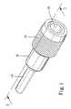
- FIG. 1is a perspective view of a chuck device for tool bits in accordance with the present invention
- FIG. 2is an exploded perspective view of FIG. 1;
- FIG. 3is a cross-sectional view taken along a line 3 — 3 in FIG. 1;
- FIG. 4is a cross-sectional view similar to FIG. 3 except for showing the chuck device to be engaged with a miniature tool bit;
- FIG. 5is a cross-sectional view similar to FIG. 4 except for showing insertion of the miniature tool bit into the chuck device;
- FIG. 6is a cross-sectional view similar to FIG. 5, except for showing the chuck device engaged with the miniature tool bit;
- FIG. 7is a cross-sectional view taken along a line 7 — 7 in FIG. 6;
- FIG. 8is a cross-sectional view similar to FIG. 5, except for showing release of the miniature tool bit from the chuck device.
- the present inventionis related to a chuck device for engagement with miniature tool bits. Therefore, before the chuck device is described, a miniature tool bit 50 is described referring to FIGS. 4 to 8 in view of an ordinary tool bit (not shown).
- An ordinary tool bitincludes a tip and a shank of a hexangular configuration.
- An annular grooveis defined in the shank of the ordinary tool bit for engagement with a ball of a chuck device.
- the miniature tool bit 50includes a tip and a shank of a hexangular structure.
- the shank of the miniature tool bit 50includes six corners 53 .
- no angular grooveis defined in the miniature tool bit 50 .
- a recess 52is defined in each of the corners 53 of the miniature tool bit 50 . At least one of the recesses 52 will be engaged with a ball of a chuck device.
- the miniature tool bit 50is formed with such a structure in order not to seriously sacrifice its already small cross-sectional area and therefore its strength.
- the chuck device for miniature tool bitswill be described referring to the drawings and initially to FIGS. 1 to 3 .
- the chuck deviceincludes a socket 10 , a sleeve 20 , a pusher 30 and a spindle 40 .
- the spindle 40may be connected with a handle (not shown) or a driving element of a pneumatic or electric device (not shown).
- the socket 10includes a tool-engaging section and a spindle-engaging section.
- a chamber 11is defined in the tool-engaging section of the socket 10 .
- the chamber 11is surrounded by a substantially cylindrical wall (not numbered) that defines six corner-receiving slots 18 for receiving the corners 53 of the miniature tool bit 50 .
- the socket 10can drive the miniature tool bit 50 .
- the socket 10includes two holes 12 defined in the tool-engaging section thereof in communication with two of the corner-receiving slots 18 .
- a ball 14is received in each of the holes 12 so that it can be engaged with one of the recesses 52 defined in the miniature tool bit 50 in order to lock the tool bit 50 to the chuck device.
- the socket 10includes an annular groove 16 defined in an external surface thereof.
- a C-ring 17is received in the annular groove 16 .
- a sleeve 20includes an annular groove 21 defined in an internal surface thereof and an annular rib 23 formed on the internal surface thereof.
- the annular groove 21 and the annular rib 23are arranged next to each other.
- An elastic element 24 and the sleeve 20are mounted on the tool-engaging section of the socket 10 .
- the elastic element 24is compressed between the C-ring 17 and the annular rib 23 of the sleeve 20 .
- the sleeve 20is biased by the elastic element 24 .
- a ring 25is securely pressed into the sleeve 20 .
- the ring 25can abut the C-ring 17 in order to retain the sleeve 20 on the socket 10 .
- the socket 10includes a chamber 13 defined in the spindle-engaging section thereof.
- the chamber 11is dimensioned smaller than the chamber 13 , thus forming an annular shoulder 15 on the internal surface of the socket 10 between the chambers 11 and 13 .
- the pusher 30includes a first recess 31 defined in a first end thereof, a second recess 32 defined in a second end thereof, an annular groove 33 defined in an external surface thereof near the second end thereof.
- the first recess 31is in compliance with an end of the miniature tool bit 50 .
- a C-ring 34is received in the annular groove 33 of the pusher 30 .
- An elastic element 45is received in the chamber 13 so that its first end is received in the second recess 32 of the pusher 30 .
- the spindle 40includes a first section 41 in which a recess 43 is defined.
- the first section 41 of the spindle 40is securely pressed into the chamber 13 .
- a second end of the elastic element 45is received in the recess 43 .
- the elastic element 45is compressed between the pusher 30 and the spindle 40 .
- the first section 41 of the spindle 40is shaped corresponding to the chamber 13 so that the socket 10 can be driven via the spindle 40 .
- the spindle 40includes a stop 44 formed next to the first section 41 .
- the stop 44 of the spindle 40is capable of preventing further insertion of the first section 41 of the spindle 40 into the chamber 13 .
- the spindle 40includes a second section 42 projecting from the stop 44 .
- the second section 42can be engaged with the handle or pneumatic or electric device.
- the sleeve 20is moved relative to the socket 10 from a position as shown in FIG. 3 to a position as shown in FIG. 4 .
- the groove 21is aligned with the balls 14 received in the hole 12 , thus allowing the balls 14 to partially enter into the annular groove 21 , thus allowing the complete clearance of the balls 14 from the chamber 11 .
- the shank of the miniature tool bit 50is inserted into the chamber 11 so as to pass by the balls 14 as shown in FIG. 5 . Referring to FIGS.
- the sleeve 20is released, thus allowing the elastic element 24 to move the sleeve 20 so that the annular rib 23 presses the balls 14 partially into one of the recesses 52 .
- the miniature tool bit 50is engaged with the chuck device.
- the sleeve 20is moved from the position as shown in FIG. 6 to a position as shown in FIG. 8 .
- the annular groove 21is aligned with the balls 14 received in the holes 12 , thus allowing the balls 14 to partially enter the annular groove 21 .
- the pusher 30pushes the shank of the miniature tool bit 50 while the shank of the miniature tool bit 50 forces the balls 14 completely out of the chamber 11 .
- the miniature tool bit 50can be removed from the chuck device.
Landscapes
- Engineering & Computer Science (AREA)
- Mechanical Engineering (AREA)
- Gripping On Spindles (AREA)
Abstract
Description
1. Field of Invention
The present invention relates to a chuck device for engagement with miniature tool bits.
2. Related Prior Art
In both U. S. Pat. Nos. 6,270,085 and 6,325,393, a chuck device is disclosed for engagement with tool bits. As shown in these patents, a tool bit 80 includes a shank and an annular groove 82 defined in the shank for engagement with a ball of the chuck device. However, such a configuration is not suitable for a miniature tool bit because such an annular groove seriously reduces cross-sectional area and therefore strength of such a miniature tool bit. Instead of an angular groove, a recess is defined in each of six corners of such a miniature tool bit. To match such a miniature tool bit, a new chuck device is needed.
It is the primary object of the present invention to provide a chuck device for engagement with miniature tool bits each including a number of corners each defining a recess.
The chuck device includes a socket, at least one ball, a first ring, an elastic element, a sleeve, a second ring and a spindle. The socket includes a chamber defined therein. The chamber includes a number of slots for receiving the corners of such a miniature tool bit. The socket includes at least one hole defined therein in communication with at least one of the corner-receiving slots. The at least one ball is received in the hole for engagement with the recess defined in at least one of the corners of the miniature tool bit. The first ring is mounted on the socket. The elastic element is mounted on the socket. The sleeve includes an annular groove defined in and an annular rib formed on an internal surface thereof. The sleeve is mounted on the socket. The elastic element is compressed between the ring and the annular rib, thus biasing the sleeve. The second ring is connected with the sleeve for engagement with the first ring, thus retaining the sleeve on the socket. The spindle is connected with the socket.
The socket may include two holes in communication with two of the slots. A ball is received in each of the holes.
The first ring may be a C-ring received in an annular groove defined in an external surface of the socket.
The second ring may be pressed into the sleeve.
The socket may include a second chamber defined therein for receiving the spindle.
The second chamber may be in communication with the first chamber. Thus, a pusher may be received in the first and second chambers for pushing the miniature tool bit. A second elastic element may be received in the second chamber for biasing the pusher.
The pusher may include a first recess defined therein for engagement with the miniature tool bit.
The pusher may include a second recess defined therein for engagement with the second elastic element.
The socket may include an annular shoulder formed between the first and second chambers. The pusher includes a third ring formed thereon for engagement with the annular shoulder, thus avoiding the pusher escaping from the second chamber.
The third ring may be a C-ring received in an annular groove defined in the pusher.
The spindle may include a first section received in the second chamber and a recess defined in the first section of the spindle for engagement with the second elastic element.
Other objects, advantages, and novel features of the invention will become more apparent from the following detailed description when taken in conjunction with the accompanying drawings.
The present invention is described in relation to embodiments as shown in the attached drawings wherein:
FIG. 1 is a perspective view of a chuck device for tool bits in accordance with the present invention;
FIG. 2 is an exploded perspective view of FIG. 1;
FIG. 3 is a cross-sectional view taken along aline 3—3 in FIG. 1;
FIG. 4 is a cross-sectional view similar to FIG. 3 except for showing the chuck device to be engaged with a miniature tool bit;
FIG. 5 is a cross-sectional view similar to FIG. 4 except for showing insertion of the miniature tool bit into the chuck device;
FIG. 6 is a cross-sectional view similar to FIG. 5, except for showing the chuck device engaged with the miniature tool bit;
FIG. 7 is a cross-sectional view taken along aline 7—7 in FIG. 6; and
FIG. 8 is a cross-sectional view similar to FIG. 5, except for showing release of the miniature tool bit from the chuck device.
As mentioned, the present invention is related to a chuck device for engagement with miniature tool bits. Therefore, before the chuck device is described, aminiature tool bit 50 is described referring to FIGS. 4 to8 in view of an ordinary tool bit (not shown). An ordinary tool bit includes a tip and a shank of a hexangular configuration. An annular groove is defined in the shank of the ordinary tool bit for engagement with a ball of a chuck device. Like the ordinary tool bit, theminiature tool bit 50 includes a tip and a shank of a hexangular structure. The shank of theminiature tool bit 50 includes sixcorners 53. Unlike the ordinary tool bit, no angular groove is defined in theminiature tool bit 50. Instead, arecess 52 is defined in each of thecorners 53 of theminiature tool bit 50. At least one of therecesses 52 will be engaged with a ball of a chuck device. Theminiature tool bit 50 is formed with such a structure in order not to seriously sacrifice its already small cross-sectional area and therefore its strength.
The chuck device for miniature tool bits according to the present invention will be described referring to the drawings and initially to FIGS. 1 to3. The chuck device includes asocket 10, asleeve 20, apusher 30 and aspindle 40. Thespindle 40 may be connected with a handle (not shown) or a driving element of a pneumatic or electric device (not shown).
Elements and features related to engagement of the chuck device with theminiature tool bit 50 will now be described. Thesocket 10 includes a tool-engaging section and a spindle-engaging section. Achamber 11 is defined in the tool-engaging section of thesocket 10. Further referring to FIG. 6, thechamber 11 is surrounded by a substantially cylindrical wall (not numbered) that defines six corner-receivingslots 18 for receiving thecorners 53 of theminiature tool bit 50. Thus, thesocket 10 can drive theminiature tool bit 50.
Thesocket 10 includes twoholes 12 defined in the tool-engaging section thereof in communication with two of the corner-receivingslots 18. Aball 14 is received in each of theholes 12 so that it can be engaged with one of therecesses 52 defined in theminiature tool bit 50 in order to lock thetool bit 50 to the chuck device. Thesocket 10 includes anannular groove 16 defined in an external surface thereof. A C-ring 17 is received in theannular groove 16.
Asleeve 20 includes anannular groove 21 defined in an internal surface thereof and anannular rib 23 formed on the internal surface thereof. Theannular groove 21 and theannular rib 23 are arranged next to each other.
Anelastic element 24 and thesleeve 20 are mounted on the tool-engaging section of thesocket 10. Theelastic element 24 is compressed between the C-ring 17 and theannular rib 23 of thesleeve 20. Thus, thesleeve 20 is biased by theelastic element 24. Aring 25 is securely pressed into thesleeve 20. Thering 25 can abut the C-ring 17 in order to retain thesleeve 20 on thesocket 10.
Now, elements and features related to automatic release of theminiature tool bit 50 from the chuck device will be described. Thesocket 10 includes achamber 13 defined in the spindle-engaging section thereof. Thechamber 11 is dimensioned smaller than thechamber 13, thus forming anannular shoulder 15 on the internal surface of thesocket 10 between thechambers
Thepusher 30 includes afirst recess 31 defined in a first end thereof, asecond recess 32 defined in a second end thereof, anannular groove 33 defined in an external surface thereof near the second end thereof. Thefirst recess 31 is in compliance with an end of theminiature tool bit 50. A C-ring 34 is received in theannular groove 33 of thepusher 30. Anelastic element 45 is received in thechamber 13 so that its first end is received in thesecond recess 32 of thepusher 30.
Thespindle 40 includes afirst section 41 in which arecess 43 is defined. Thefirst section 41 of thespindle 40 is securely pressed into thechamber 13. A second end of theelastic element 45 is received in therecess 43. Theelastic element 45 is compressed between thepusher 30 and thespindle 40.
Elements and features related to engagement of the chuck device with the handle or the driving element of the pneumatic or electric device will now be described. Thefirst section 41 of thespindle 40 is shaped corresponding to thechamber 13 so that thesocket 10 can be driven via thespindle 40. Thespindle 40 includes astop 44 formed next to thefirst section 41. Thestop 44 of thespindle 40 is capable of preventing further insertion of thefirst section 41 of thespindle 40 into thechamber 13. Thespindle 40 includes asecond section 42 projecting from thestop 44. Thesecond section 42 can be engaged with the handle or pneumatic or electric device.
The engagement of theminiature tool bit 50 with the chuck device will be described referring to FIGS. 3 to7. Firstly, thesleeve 20 is moved relative to thesocket 10 from a position as shown in FIG. 3 to a position as shown in FIG.4. In this position, thegroove 21 is aligned with theballs 14 received in thehole 12, thus allowing theballs 14 to partially enter into theannular groove 21, thus allowing the complete clearance of theballs 14 from thechamber 11. Then, the shank of theminiature tool bit 50 is inserted into thechamber 11 so as to pass by theballs 14 as shown in FIG.5. Referring to FIGS. 6 and 7, thesleeve 20 is released, thus allowing theelastic element 24 to move thesleeve 20 so that theannular rib 23 presses theballs 14 partially into one of therecesses 52. Thus, theminiature tool bit 50 is engaged with the chuck device.
Now, the release of theminiature tool bit 50 from the chuck device will be described. Firstly, thesleeve 20 is moved from the position as shown in FIG. 6 to a position as shown in FIG.8. In this position, theannular groove 21 is aligned with theballs 14 received in theholes 12, thus allowing theballs 14 to partially enter theannular groove 21. Biased by theelastic element 45, thepusher 30 pushes the shank of theminiature tool bit 50 while the shank of theminiature tool bit 50 forces theballs 14 completely out of thechamber 11. Thus, theminiature tool bit 50 can be removed from the chuck device.
The preferred embodiment of the present invention has been described in detail for purposes of illustration. Those skilled in the art can derive several variations from these embodiments after a study of this patent specification. Therefore, these embodiments shall not limit the scope of the present invention. The scope of the present invention can only be defined in the claims attached to and taken as a portion of this patent specification.
Claims (13)
1. A chuck device for engagement with a miniature tool bit including a recess, the chuck device including:
a socket including a chamber that is defied therein for receiving the miniature tool bit and at least one hole defined therein in communication with the chamber;
a ball received in the at least one hole for engagement with the recess defined in the miniature tool bit;
a first ring removably mounted on and around the socket;
an elastic element mounted on the socket;
a sleeve including an annular groove defined in and an annular rib formed on an internal surface thereof, wherein the sleeve is mounted on the socket so that the elastic element is compressed between the ring and the annular rib, thus biasing the sleeve;
a second ring removably connected with the sleeve for abutting the first ring, thus retaining the sleeve on the socket; and
a spindle connected with the socket.
2. The chuck device according toclaim 1 wherein the chamber includes a number of slots receiving a number of corners of the miniature tool bit, with each of the number of corners each defining the recess, wherein the socket includes two holes in communication with two of the slots, wherein a ball is received in each of the holes.
3. The chuck device according toclaim 1 wherein the first ring is a C-ring received in an annular groove defined in an external surface of the socket.
4. The chuck device according toclaim 1 wherein the second ring is pressed into the sleeve.
5. The chuck device according toclaim 1 wherein the socket includes a second chamber defined therein for receiving the spindle.
6. The chuck device according toclaim 5 wherein the second chamber is in communication with the first chamber.
7. The chuck device according toclaim 6 including a pusher received in the first and second chambers for pushing the miniature tool bit.
8. The chuck device according toclaim 7 including a second elastic element received in the second chamber for biasing the pusher.
9. The chuck device according toclaim 8 wherein the pusher includes a first recess defined therein for engagement with the miniature tool bit.
10. The chuck device according toclaim 9 wherein the pusher includes a second recess defined therein for engagement with the second elastic element.
11. The chuck device according toclaim 8 wherein the socket includes an annular shoulder formed between the first and second chambers, wherein the pusher includes a third ring formed thereon for abutting the annular shoulder, thus avoiding the pusher escaping from the second chamber.
12. The chuck device according toclaim 11 wherein the third ring is a C-ring received in an annular groove defined in the pusher.
13. The chuck device according toclaim 9 wherein the spindle includes a first section received in the second chamber and a recess defined in the first section of the spindle for engagement with the second elastic element.
Priority Applications (3)
| Application Number | Priority Date | Filing Date | Title |
|---|---|---|---|
| US10/104,118US6637755B2 (en) | 2002-03-22 | 2002-03-22 | Chuck device for miniature tool bits |
| DE10249199ADE10249199B4 (en) | 2002-03-22 | 2002-10-22 | Feeding device for miniature tool bits |
| US10/634,193US20040026878A1 (en) | 2002-03-22 | 2003-08-04 | Chuck device for miniature tool bits |
Applications Claiming Priority (2)
| Application Number | Priority Date | Filing Date | Title |
|---|---|---|---|
| US10/104,118US6637755B2 (en) | 2002-03-22 | 2002-03-22 | Chuck device for miniature tool bits |
| DE10249199ADE10249199B4 (en) | 2002-03-22 | 2002-10-22 | Feeding device for miniature tool bits |
Related Child Applications (1)
| Application Number | Title | Priority Date | Filing Date |
|---|---|---|---|
| US10/634,193Continuation-In-PartUS20040026878A1 (en) | 2002-03-22 | 2003-08-04 | Chuck device for miniature tool bits |
Publications (2)
| Publication Number | Publication Date |
|---|---|
| US20030178794A1 US20030178794A1 (en) | 2003-09-25 |
| US6637755B2true US6637755B2 (en) | 2003-10-28 |
Family
ID=32851827
Family Applications (1)
| Application Number | Title | Priority Date | Filing Date |
|---|---|---|---|
| US10/104,118Expired - LifetimeUS6637755B2 (en) | 2002-03-22 | 2002-03-22 | Chuck device for miniature tool bits |
Country Status (2)
| Country | Link |
|---|---|
| US (1) | US6637755B2 (en) |
| DE (1) | DE10249199B4 (en) |
Cited By (72)
| Publication number | Priority date | Publication date | Assignee | Title |
|---|---|---|---|---|
| US20040026878A1 (en)* | 2002-03-22 | 2004-02-12 | Tsai-Ching Chen | Chuck device for miniature tool bits |
| US20040164503A1 (en)* | 2003-02-21 | 2004-08-26 | Wei-Chuan Fan-Chiang | Bit quick-release device |
| US20040173061A1 (en)* | 2002-10-16 | 2004-09-09 | Mou-Tang Liou | Tool including bit and handle |
| US20050116429A1 (en)* | 2003-12-01 | 2005-06-02 | Sheng-Ming Chang | Fast and convenient operation structure of a screwdriver head socket |
| US6953196B1 (en)* | 2003-03-31 | 2005-10-11 | Daniel Huang | Non-inflation adapter for prompt engagement with a shank of a screw driver and a handle |
| US20060022416A1 (en)* | 2004-07-30 | 2006-02-02 | Chang-Ying Chen | Rapid detached connecting device |
| US20060097464A1 (en)* | 2002-06-10 | 2006-05-11 | Martin Strauch | Chuck for receiving tools operated by rotating around the axis thereof |
| US20060145431A1 (en)* | 2003-12-01 | 2006-07-06 | Chang Sheng M | Tool connecting device |
| US20060163823A1 (en)* | 2005-01-25 | 2006-07-27 | Zu-Shung Shu | Tool joint |
| US20070152408A1 (en)* | 2005-12-29 | 2007-07-05 | Black & Decker Inc. | Universal tool bit shank |
| US20070204730A1 (en)* | 2006-03-01 | 2007-09-06 | Jacques Rajotte | Screw driving device |
| US20070227311A1 (en)* | 2006-04-04 | 2007-10-04 | Shyh-Ming Wang | Socket for a wrench |
| US20080036163A1 (en)* | 2006-08-08 | 2008-02-14 | Friedrich Kurz | Quick chucking unit, with sealing unit, and quick chucking system |
| USD563750S1 (en) | 2005-12-29 | 2008-03-11 | Black & Decker Inc. | Universal shank for tools |
| US20080072718A1 (en)* | 2006-09-25 | 2008-03-27 | Kuo-Chen Liu | Device for locking and releasing a screw bit |
| US20080111323A1 (en)* | 2006-11-09 | 2008-05-15 | Westport Medical, Inc. | Bit holders |
| US20080121075A1 (en)* | 2006-11-23 | 2008-05-29 | Meng Chi-Fen | Device for locking and releasing a scrwe bit |
| US7387051B1 (en) | 2007-03-27 | 2008-06-17 | Hsin Ying Enterprise Co., Ltd. | Tool device for driving various tool members |
| US7392727B1 (en) | 2007-03-27 | 2008-07-01 | Hsin Ying Enterprise Co., Ltd. | Tool device for driving various tool members |
| US20080185793A1 (en)* | 2005-03-23 | 2008-08-07 | Franz Haimer Maschinenbau Kg | Tool Holder |
| US20080190251A1 (en)* | 2007-02-08 | 2008-08-14 | Daniel Huang | Adapter coupling device |
| USD575609S1 (en) | 2005-12-29 | 2008-08-26 | Black & Decker Inc. | Universal shank for tools |
| US20080217870A1 (en)* | 2007-03-07 | 2008-09-11 | Makita Corporation | Bit mounting devices |
| US20080256774A1 (en)* | 2006-03-01 | 2008-10-23 | Jacques Rajotte | Screw driving method |
| US20080292419A1 (en)* | 2006-04-10 | 2008-11-27 | Eugen Hild | Tool Holder For a Rotary Hammer |
| US20090008886A1 (en)* | 2007-07-02 | 2009-01-08 | Zu-Shung Shu | Chuck |
| US7481136B2 (en) | 2007-04-24 | 2009-01-27 | Hsin Ying Enterprise Co., Ltd. | Tool device for driving various tool members |
| US20090139378A1 (en)* | 2007-11-30 | 2009-06-04 | Hsin Ying Enterprise Co., Ltd. | Driver tool having adjustable structure |
| US20090139379A1 (en)* | 2007-11-30 | 2009-06-04 | Hsin Ying Enterprise Co., Ltd. | Driver tool for driving various tool members |
| US20090151520A1 (en)* | 2006-04-04 | 2009-06-18 | Shyh-Ming Wang | Socket for wrenches |
| US20090188352A1 (en)* | 2007-02-08 | 2009-07-30 | Daniel Huang | Adapter coupling device |
| US7581470B1 (en)* | 2008-11-25 | 2009-09-01 | Jui-Min Huang | Universal screwdriver bit set |
| US20090256319A1 (en)* | 2008-04-09 | 2009-10-15 | Seymour Daniel R | Quick change chuck with led lighting |
| US20090309317A1 (en)* | 2008-06-11 | 2009-12-17 | Bobby Hu | Chuck for Bit |
| US20090308629A1 (en)* | 2005-05-31 | 2009-12-17 | Yukiwa Seiko Kabushiki Kaisha | Rotating tool |
| US20090309316A1 (en)* | 2008-06-11 | 2009-12-17 | Bobby Hu | Chuck for Bit |
| EP2151304A2 (en) | 2008-08-06 | 2010-02-10 | Bobby Hu | Tool holding device |
| KR100946961B1 (en) | 2009-08-19 | 2010-03-16 | 주식회사 대성지티 | Air beveler changing a cutter easily |
| US20100101382A1 (en)* | 2008-10-24 | 2010-04-29 | Chen-Tsung Chen | Hand Tool that can Replace Tips Easily and Quickly |
| US20100219593A1 (en)* | 2009-02-27 | 2010-09-02 | Black & Decker Inc. | Bit Retention Device |
| US20100225073A1 (en)* | 2006-11-09 | 2010-09-09 | Douglas Roy Porter | Bit holders |
| CN101858391A (en)* | 2009-04-09 | 2010-10-13 | 鸿富锦精密工业(深圳)有限公司 | connecting device |
| US20100270759A1 (en)* | 2005-11-30 | 2010-10-28 | Daniel Huang | Tool bit holder assembly |
| US20100282485A1 (en)* | 2009-05-05 | 2010-11-11 | Black & Decker Inc. | Power tool with integrated bit retention device |
| US20100282034A1 (en)* | 2009-05-11 | 2010-11-11 | Jui-Min Huang | Connecting rod of a tool head |
| AU2008201298B2 (en)* | 2008-03-19 | 2014-06-26 | Jacques Rajotte | Screw Driving Device |
| US8800999B2 (en) | 2009-02-27 | 2014-08-12 | Black & Decker Inc. | Bit retention device |
| DE202015100137U1 (en) | 2015-01-14 | 2015-03-26 | Good Year Hardware Co., Ltd. | Holder for tool inserts |
| US20150102567A1 (en)* | 2013-10-16 | 2015-04-16 | Fu-Yi Chan | Tool joint |
| US20150143966A1 (en)* | 2013-06-12 | 2015-05-28 | Andrew Arlin Pischke | Locking Quick Release Protective Cap Assembly For Pocket Tools |
| DE102014104188A1 (en) | 2014-01-22 | 2015-07-23 | Good Year Hardware Co., Ltd. | Tool adapter with position limiting rod |
| CN104802119A (en)* | 2014-01-28 | 2015-07-29 | 峪亿五金股份有限公司 | Adapter structure of the tool head |
| CN104802118A (en)* | 2014-01-28 | 2015-07-29 | 峪亿五金股份有限公司 | Tool head adapters with stops |
| US9156147B2 (en) | 2012-02-15 | 2015-10-13 | Black & Decker Inc. | Quick change bit holder with ring magnet |
| US9227309B2 (en) | 2012-02-15 | 2016-01-05 | Black & Decker Inc. | Quick change bit holder with ring magnet |
| TWI551407B (en)* | 2014-06-20 | 2016-10-01 | 有祿企業股份有限公司 | Push-on quick release screwdriver |
| US9505108B2 (en) | 2012-02-15 | 2016-11-29 | Black & Decker Inc. | Bit holder with floating magnet sleeve |
| TWI562872B (en)* | 2015-06-12 | 2016-12-21 | Jei Mou Ind Co Ltd | Rotatable multi-purpose tool structure |
| USD789761S1 (en) | 2015-11-02 | 2017-06-20 | Black & Decker Inc. | Torsion bit |
| DE102016106594B3 (en)* | 2016-03-01 | 2017-07-06 | Good Year Hardware Co., Ltd. | Connecting device for screwdriver bit |
| US9943946B2 (en) | 2012-02-15 | 2018-04-17 | Black & Decker Inc. | Tool bits with floating magnet sleeves |
| US10150205B2 (en) | 2012-02-15 | 2018-12-11 | Black & Decker Inc. | Fastening tools with floating magnet sleeves |
| US10343266B2 (en) | 2015-12-10 | 2019-07-09 | Milwaukee Electric Tool Corporation | Bit holder assembly |
| USD861050S1 (en)* | 2017-10-25 | 2019-09-24 | Jung-ping Li | Eccentric shaft for a grinding machine |
| US10569343B2 (en)* | 2017-11-06 | 2020-02-25 | Ingersoll-Rand Company | Quick locking and releasing attachment retainer |
| TWI695760B (en)* | 2014-06-30 | 2020-06-11 | 美商德派信迪思產品公司 | Screwdriver |
| US10821579B2 (en) | 2016-11-07 | 2020-11-03 | Jacques Rajotte | Screw driving device for use with an impact driver |
| US10974374B2 (en) | 2018-12-19 | 2021-04-13 | Jacques Rajotte | Impact driver screw driving device with depth adjustment |
| US11065744B2 (en) | 2018-07-20 | 2021-07-20 | Milwaukee Electric Tool Corporation | Tool bit holder |
| USD955453S1 (en)* | 2020-10-01 | 2022-06-21 | Shukla Medical | Drill bit |
| USD959521S1 (en)* | 2020-11-16 | 2022-08-02 | Adam Abrams | Tool |
| US20230364753A1 (en)* | 2022-05-12 | 2023-11-16 | Kabo Tool Company | Socket |
Families Citing this family (16)
| Publication number | Priority date | Publication date | Assignee | Title |
|---|---|---|---|---|
| DE10141668A1 (en)* | 2001-08-25 | 2003-03-06 | Werner Hermann Wera Werke | Chuck for tools, especially screwdriver bits |
| TW580973U (en)* | 2002-12-16 | 2004-03-21 | Mu-Mau Tzeng | Tool structure capable of drilling, chamfering and tightening |
| US7052022B2 (en)* | 2003-05-13 | 2006-05-30 | Snap-On Incorporated | Chuck for pneumatic hammer |
| US8137370B2 (en)* | 2005-11-02 | 2012-03-20 | Stryker Corporation | Powered surgical handpiece with improved latch mechanism and rotary to oscillating output drive |
| US20090033042A1 (en)* | 2006-08-08 | 2009-02-05 | Rinner James A | Tool Chuck |
| DE102007032284A1 (en)* | 2007-07-11 | 2009-01-15 | Shu, Zu-Shung, Ta Li City | Clamping device for use with pneumatic or electrical turning tool, has pressing element movably arranged in base, for pressing tip in hexagonal opening in release position of tip retaining device |
| US20090224492A1 (en)* | 2008-03-10 | 2009-09-10 | Jack Lin | Bit connector with quick release device |
| DE102011007433A1 (en)* | 2010-04-20 | 2011-12-08 | Robert Bosch Gmbh | Hand machine tool device |
| CN104139378B (en)* | 2013-05-10 | 2017-05-03 | 苏州宝时得电动工具有限公司 | Clamping device and power tool |
| CN103144772B (en)* | 2013-03-01 | 2015-05-27 | 上海大学 | Unhooking device controlled by steering engine |
| TWI556922B (en)* | 2014-01-22 | 2016-11-11 | Good Year Hardware Co Ltd | Tool head structure |
| WO2017058050A1 (en)* | 2015-09-28 | 2017-04-06 | Валентин Сергеевич КУЗНЕЦОВ | Universal hammer for a hammer drill |
| US20190201987A1 (en)* | 2017-12-30 | 2019-07-04 | Kwon J. PARK | Bit adapter |
| TWI650213B (en)* | 2018-08-10 | 2019-02-11 | 峪億五金股份有限公司 | Double positioning bead tool head post |
| US11925967B2 (en)* | 2021-11-15 | 2024-03-12 | Jake Matthew Thomas | Tool kit with quick-connect coupling for paintless dent removal |
| US11826807B2 (en)* | 2021-11-15 | 2023-11-28 | Jake Matthew Thomas | Handle and a kit of tools for paintless dent removal |
Citations (7)
| Publication number | Priority date | Publication date | Assignee | Title |
|---|---|---|---|---|
| US1124981A (en)* | 1913-02-20 | 1915-01-12 | William Arthur Weaver | Tool-holder. |
| US5188378A (en)* | 1990-01-11 | 1993-02-23 | Wera Werk Hermann Werner Gmbh & Co. | Chuck for polygonal shank ends of tools |
| US5934384A (en)* | 1998-04-27 | 1999-08-10 | Wang; Peter | Transmission shaft and bit mounting arrangement of a motor-driven hand drill |
| US6135462A (en)* | 1999-05-24 | 2000-10-24 | Gary Sebastian | Snap-in chuck |
| US6270085B1 (en)* | 1999-10-01 | 2001-08-07 | Tsai-Ching Chen | Chuck device for tool bits |
| US6311989B1 (en)* | 1999-07-13 | 2001-11-06 | Werner Hermann Wera Werke | Chuck for screwdriver inserts |
| US6325393B1 (en)* | 1999-10-01 | 2001-12-04 | Tsai-Ching Chen | Chuck device for tools |
Family Cites Families (6)
| Publication number | Priority date | Publication date | Assignee | Title |
|---|---|---|---|---|
| US5013194A (en)* | 1988-09-08 | 1991-05-07 | Wienhold James L | Chuck assembly for tool bits |
| US6199872B1 (en)* | 1999-08-13 | 2001-03-13 | Maxtech Consumer Products, L.L.C. | Quick-release mechanism for screwdriver bits and the like |
| DE29915152U1 (en)* | 1999-08-30 | 2000-01-20 | Reinshagen, Helmut, 42111 Wuppertal | Bit holder |
| US6457916B2 (en)* | 1999-11-15 | 2002-10-01 | Insty-Bit, Inc. | Locking quick-change chuck assembly |
| WO2001096052A1 (en)* | 2000-06-09 | 2001-12-20 | Jore Corporation | Workpiece connector for a power tool |
| DE20201012U1 (en)* | 2002-01-24 | 2002-05-08 | Wiha Werkzeuge GmbH, 78136 Schonach | Holder for screwdriver bits |
- 2002
- 2002-03-22USUS10/104,118patent/US6637755B2/ennot_activeExpired - Lifetime
- 2002-10-22DEDE10249199Apatent/DE10249199B4/ennot_activeExpired - Lifetime
Patent Citations (7)
| Publication number | Priority date | Publication date | Assignee | Title |
|---|---|---|---|---|
| US1124981A (en)* | 1913-02-20 | 1915-01-12 | William Arthur Weaver | Tool-holder. |
| US5188378A (en)* | 1990-01-11 | 1993-02-23 | Wera Werk Hermann Werner Gmbh & Co. | Chuck for polygonal shank ends of tools |
| US5934384A (en)* | 1998-04-27 | 1999-08-10 | Wang; Peter | Transmission shaft and bit mounting arrangement of a motor-driven hand drill |
| US6135462A (en)* | 1999-05-24 | 2000-10-24 | Gary Sebastian | Snap-in chuck |
| US6311989B1 (en)* | 1999-07-13 | 2001-11-06 | Werner Hermann Wera Werke | Chuck for screwdriver inserts |
| US6270085B1 (en)* | 1999-10-01 | 2001-08-07 | Tsai-Ching Chen | Chuck device for tool bits |
| US6325393B1 (en)* | 1999-10-01 | 2001-12-04 | Tsai-Ching Chen | Chuck device for tools |
Cited By (113)
| Publication number | Priority date | Publication date | Assignee | Title |
|---|---|---|---|---|
| US20040026878A1 (en)* | 2002-03-22 | 2004-02-12 | Tsai-Ching Chen | Chuck device for miniature tool bits |
| US7469909B2 (en)* | 2002-06-10 | 2008-12-30 | Wera Werk Hermann Werner Gmbh & Co. Kg | Chuck for receiving tools operated by rotating around the axis thereof |
| US20060097464A1 (en)* | 2002-06-10 | 2006-05-11 | Martin Strauch | Chuck for receiving tools operated by rotating around the axis thereof |
| US20040173061A1 (en)* | 2002-10-16 | 2004-09-09 | Mou-Tang Liou | Tool including bit and handle |
| US7036404B2 (en)* | 2002-10-16 | 2006-05-02 | Mou-Tang Liou | Tool including bit and handle |
| US20040164503A1 (en)* | 2003-02-21 | 2004-08-26 | Wei-Chuan Fan-Chiang | Bit quick-release device |
| US6953196B1 (en)* | 2003-03-31 | 2005-10-11 | Daniel Huang | Non-inflation adapter for prompt engagement with a shank of a screw driver and a handle |
| US20050116429A1 (en)* | 2003-12-01 | 2005-06-02 | Sheng-Ming Chang | Fast and convenient operation structure of a screwdriver head socket |
| US20060145431A1 (en)* | 2003-12-01 | 2006-07-06 | Chang Sheng M | Tool connecting device |
| US7114728B2 (en)* | 2004-07-30 | 2006-10-03 | Chang-Ying Chen | Rapid detached connecting device |
| US20060022416A1 (en)* | 2004-07-30 | 2006-02-02 | Chang-Ying Chen | Rapid detached connecting device |
| US20060163823A1 (en)* | 2005-01-25 | 2006-07-27 | Zu-Shung Shu | Tool joint |
| US7195247B2 (en)* | 2005-01-25 | 2007-03-27 | Zu-Shung Shu | Tool joint |
| US20080185793A1 (en)* | 2005-03-23 | 2008-08-07 | Franz Haimer Maschinenbau Kg | Tool Holder |
| US7845428B2 (en)* | 2005-05-31 | 2010-12-07 | Yukiwa Seiko Kabushiki Kaisha | Rotating tool |
| US20090308629A1 (en)* | 2005-05-31 | 2009-12-17 | Yukiwa Seiko Kabushiki Kaisha | Rotating tool |
| US20100270759A1 (en)* | 2005-11-30 | 2010-10-28 | Daniel Huang | Tool bit holder assembly |
| US7726664B2 (en) | 2005-12-29 | 2010-06-01 | Black & Decker Inc. | Universal tool bit shank |
| USD563750S1 (en) | 2005-12-29 | 2008-03-11 | Black & Decker Inc. | Universal shank for tools |
| US20100133762A1 (en)* | 2005-12-29 | 2010-06-03 | Black & Decker Inc. | Universal Tool Bit Shank |
| US20070152408A1 (en)* | 2005-12-29 | 2007-07-05 | Black & Decker Inc. | Universal tool bit shank |
| USD575609S1 (en) | 2005-12-29 | 2008-08-26 | Black & Decker Inc. | Universal shank for tools |
| US7896357B2 (en) | 2005-12-29 | 2011-03-01 | Black & Decker Inc. | Universal tool bit shank |
| US20130340576A1 (en)* | 2006-03-01 | 2013-12-26 | Jacques Rajotte | Screw Driving Device |
| US9302377B2 (en)* | 2006-03-01 | 2016-04-05 | Jacques Rajotte | Screw driving device |
| US7387054B2 (en)* | 2006-03-01 | 2008-06-17 | Jacques Rajotte | Screw driving device |
| US20080256774A1 (en)* | 2006-03-01 | 2008-10-23 | Jacques Rajotte | Screw driving method |
| US20070204730A1 (en)* | 2006-03-01 | 2007-09-06 | Jacques Rajotte | Screw driving device |
| US7752946B2 (en)* | 2006-04-04 | 2010-07-13 | Shyh-Ming Wang | Socket for wrenches |
| US20090151520A1 (en)* | 2006-04-04 | 2009-06-18 | Shyh-Ming Wang | Socket for wrenches |
| US20070227311A1 (en)* | 2006-04-04 | 2007-10-04 | Shyh-Ming Wang | Socket for a wrench |
| US20080292419A1 (en)* | 2006-04-10 | 2008-11-27 | Eugen Hild | Tool Holder For a Rotary Hammer |
| US20120193115A1 (en)* | 2006-04-10 | 2012-08-02 | Eugen Hild | Tool holder for a rotary hammer |
| US8210545B2 (en)* | 2006-04-10 | 2012-07-03 | Robert Bosch Gmbh | Tool holder for a rotary hammer |
| US20080036163A1 (en)* | 2006-08-08 | 2008-02-14 | Friedrich Kurz | Quick chucking unit, with sealing unit, and quick chucking system |
| US8152174B2 (en) | 2006-08-08 | 2012-04-10 | Schunk Gmbh & Co. Kg Spann- Und Greiftechnik | Quick chucking unit, with sealing unit, and quick chucking system |
| US20080072718A1 (en)* | 2006-09-25 | 2008-03-27 | Kuo-Chen Liu | Device for locking and releasing a screw bit |
| US7424841B2 (en)* | 2006-09-25 | 2008-09-16 | Kuo-Chen Liu | Device for locking and releasing a screw bit |
| US20080111323A1 (en)* | 2006-11-09 | 2008-05-15 | Westport Medical, Inc. | Bit holders |
| US8882113B2 (en) | 2006-11-09 | 2014-11-11 | Westport Medical, Inc. | Bit holders |
| US20100225073A1 (en)* | 2006-11-09 | 2010-09-09 | Douglas Roy Porter | Bit holders |
| US7922180B2 (en)* | 2006-11-23 | 2011-04-12 | Chi-Fen Meng | Device for locking and releasing a screw bit |
| US20080121075A1 (en)* | 2006-11-23 | 2008-05-29 | Meng Chi-Fen | Device for locking and releasing a scrwe bit |
| US7891275B2 (en)* | 2007-02-08 | 2011-02-22 | Daniel Huang | Adapter coupling device |
| US20090188352A1 (en)* | 2007-02-08 | 2009-07-30 | Daniel Huang | Adapter coupling device |
| US20080190251A1 (en)* | 2007-02-08 | 2008-08-14 | Daniel Huang | Adapter coupling device |
| US7448302B2 (en)* | 2007-02-08 | 2008-11-11 | Daniel Huang | Adapter coupling device |
| US8172236B2 (en)* | 2007-03-07 | 2012-05-08 | Makita Corporation | Bit mounting devices |
| US20080217870A1 (en)* | 2007-03-07 | 2008-09-11 | Makita Corporation | Bit mounting devices |
| US7392727B1 (en) | 2007-03-27 | 2008-07-01 | Hsin Ying Enterprise Co., Ltd. | Tool device for driving various tool members |
| US7387051B1 (en) | 2007-03-27 | 2008-06-17 | Hsin Ying Enterprise Co., Ltd. | Tool device for driving various tool members |
| US7481136B2 (en) | 2007-04-24 | 2009-01-27 | Hsin Ying Enterprise Co., Ltd. | Tool device for driving various tool members |
| US20090008886A1 (en)* | 2007-07-02 | 2009-01-08 | Zu-Shung Shu | Chuck |
| US20090139379A1 (en)* | 2007-11-30 | 2009-06-04 | Hsin Ying Enterprise Co., Ltd. | Driver tool for driving various tool members |
| US20090139378A1 (en)* | 2007-11-30 | 2009-06-04 | Hsin Ying Enterprise Co., Ltd. | Driver tool having adjustable structure |
| AU2008201298B2 (en)* | 2008-03-19 | 2014-06-26 | Jacques Rajotte | Screw Driving Device |
| US20090256319A1 (en)* | 2008-04-09 | 2009-10-15 | Seymour Daniel R | Quick change chuck with led lighting |
| US20090311062A1 (en)* | 2008-06-11 | 2009-12-17 | Bobby Hu | Chuck for Bit |
| US20090309316A1 (en)* | 2008-06-11 | 2009-12-17 | Bobby Hu | Chuck for Bit |
| US8413996B2 (en)* | 2008-06-11 | 2013-04-09 | Bobby Hu | Chuck for bit |
| US8366121B2 (en)* | 2008-06-11 | 2013-02-05 | Bobby Hu | Chuck for bit |
| US8366120B2 (en)* | 2008-06-11 | 2013-02-05 | Bobby Hu | Chuck for bit |
| US20090309317A1 (en)* | 2008-06-11 | 2009-12-17 | Bobby Hu | Chuck for Bit |
| US20100031787A1 (en)* | 2008-08-06 | 2010-02-11 | Bobby Hu | Tool Holding Device |
| US7913592B2 (en) | 2008-08-06 | 2011-03-29 | Bobby Hu | Tool holding device |
| EP2151304A2 (en) | 2008-08-06 | 2010-02-10 | Bobby Hu | Tool holding device |
| EP2517836A2 (en) | 2008-08-06 | 2012-10-31 | Bobby Hu | Tool holding device |
| US20100101382A1 (en)* | 2008-10-24 | 2010-04-29 | Chen-Tsung Chen | Hand Tool that can Replace Tips Easily and Quickly |
| US8267408B2 (en)* | 2008-10-24 | 2012-09-18 | Chen-Tsung Chen | Hand tool that can replace tips easily and quickly |
| US7581470B1 (en)* | 2008-11-25 | 2009-09-01 | Jui-Min Huang | Universal screwdriver bit set |
| US9067266B2 (en)* | 2009-02-27 | 2015-06-30 | Black & Decker Inc. | Bit retention device |
| US20140312578A1 (en)* | 2009-02-27 | 2014-10-23 | Black & Decker Inc. | Bit retention device |
| US20100219593A1 (en)* | 2009-02-27 | 2010-09-02 | Black & Decker Inc. | Bit Retention Device |
| US8800999B2 (en) | 2009-02-27 | 2014-08-12 | Black & Decker Inc. | Bit retention device |
| US8622401B2 (en)* | 2009-02-27 | 2014-01-07 | Black & Decker Inc. | Bit retention device |
| US20100260537A1 (en)* | 2009-04-09 | 2010-10-14 | Hong Fu Jin Precision Industry (Shenzhen) Co., Ltd | Connecting structure for swivel shafts |
| CN101858391A (en)* | 2009-04-09 | 2010-10-13 | 鸿富锦精密工业(深圳)有限公司 | connecting device |
| US20100282485A1 (en)* | 2009-05-05 | 2010-11-11 | Black & Decker Inc. | Power tool with integrated bit retention device |
| US8381830B2 (en) | 2009-05-05 | 2013-02-26 | Black & Decker Inc. | Power tool with integrated bit retention device |
| US20100282034A1 (en)* | 2009-05-11 | 2010-11-11 | Jui-Min Huang | Connecting rod of a tool head |
| US8240233B2 (en)* | 2009-05-11 | 2012-08-14 | Jui-Min Huang | Connecting rod of a tool head |
| KR100946961B1 (en) | 2009-08-19 | 2010-03-16 | 주식회사 대성지티 | Air beveler changing a cutter easily |
| US9227309B2 (en) | 2012-02-15 | 2016-01-05 | Black & Decker Inc. | Quick change bit holder with ring magnet |
| US10040179B2 (en) | 2012-02-15 | 2018-08-07 | Black & Decker Inc. | Fastener tool assemblies |
| US10150205B2 (en) | 2012-02-15 | 2018-12-11 | Black & Decker Inc. | Fastening tools with floating magnet sleeves |
| US10556329B2 (en) | 2012-02-15 | 2020-02-11 | Black & Decker Inc. | Tool bits with floating magnet sleeves |
| US9156147B2 (en) | 2012-02-15 | 2015-10-13 | Black & Decker Inc. | Quick change bit holder with ring magnet |
| US9505108B2 (en) | 2012-02-15 | 2016-11-29 | Black & Decker Inc. | Bit holder with floating magnet sleeve |
| US9943946B2 (en) | 2012-02-15 | 2018-04-17 | Black & Decker Inc. | Tool bits with floating magnet sleeves |
| US20150143966A1 (en)* | 2013-06-12 | 2015-05-28 | Andrew Arlin Pischke | Locking Quick Release Protective Cap Assembly For Pocket Tools |
| US20150102567A1 (en)* | 2013-10-16 | 2015-04-16 | Fu-Yi Chan | Tool joint |
| US9381627B2 (en) | 2014-01-22 | 2016-07-05 | Good Year Hardware Co., Ltd. | Tool bit adapter having a position-limit rod |
| DE102014104188B4 (en) | 2014-01-22 | 2020-01-23 | Good Year Hardware Co., Ltd. | Tool adapter with position limiting rod |
| DE102014104188A1 (en) | 2014-01-22 | 2015-07-23 | Good Year Hardware Co., Ltd. | Tool adapter with position limiting rod |
| CN104802118A (en)* | 2014-01-28 | 2015-07-29 | 峪亿五金股份有限公司 | Tool head adapters with stops |
| CN104802119A (en)* | 2014-01-28 | 2015-07-29 | 峪亿五金股份有限公司 | Adapter structure of the tool head |
| CN104802118B (en)* | 2014-01-28 | 2017-12-05 | 峪亿五金股份有限公司 | Tool head extension rod with limiting block |
| TWI551407B (en)* | 2014-06-20 | 2016-10-01 | 有祿企業股份有限公司 | Push-on quick release screwdriver |
| TWI695760B (en)* | 2014-06-30 | 2020-06-11 | 美商德派信迪思產品公司 | Screwdriver |
| DE202015100137U1 (en) | 2015-01-14 | 2015-03-26 | Good Year Hardware Co., Ltd. | Holder for tool inserts |
| TWI562872B (en)* | 2015-06-12 | 2016-12-21 | Jei Mou Ind Co Ltd | Rotatable multi-purpose tool structure |
| USD789761S1 (en) | 2015-11-02 | 2017-06-20 | Black & Decker Inc. | Torsion bit |
| USD841425S1 (en) | 2015-11-02 | 2019-02-26 | Black & Decker Inc. | Torsion bit |
| US10343266B2 (en) | 2015-12-10 | 2019-07-09 | Milwaukee Electric Tool Corporation | Bit holder assembly |
| DE102016106594B3 (en)* | 2016-03-01 | 2017-07-06 | Good Year Hardware Co., Ltd. | Connecting device for screwdriver bit |
| US10821579B2 (en) | 2016-11-07 | 2020-11-03 | Jacques Rajotte | Screw driving device for use with an impact driver |
| USD861050S1 (en)* | 2017-10-25 | 2019-09-24 | Jung-ping Li | Eccentric shaft for a grinding machine |
| US10569343B2 (en)* | 2017-11-06 | 2020-02-25 | Ingersoll-Rand Company | Quick locking and releasing attachment retainer |
| US11065744B2 (en) | 2018-07-20 | 2021-07-20 | Milwaukee Electric Tool Corporation | Tool bit holder |
| US10974374B2 (en) | 2018-12-19 | 2021-04-13 | Jacques Rajotte | Impact driver screw driving device with depth adjustment |
| USD955453S1 (en)* | 2020-10-01 | 2022-06-21 | Shukla Medical | Drill bit |
| USD959521S1 (en)* | 2020-11-16 | 2022-08-02 | Adam Abrams | Tool |
| US20230364753A1 (en)* | 2022-05-12 | 2023-11-16 | Kabo Tool Company | Socket |
Also Published As
| Publication number | Publication date |
|---|---|
| DE10249199A1 (en) | 2004-05-13 |
| US20030178794A1 (en) | 2003-09-25 |
| DE10249199B4 (en) | 2007-12-06 |
Similar Documents
| Publication | Publication Date | Title |
|---|---|---|
| US6637755B2 (en) | Chuck device for miniature tool bits | |
| US6874791B2 (en) | Chuck apparatus | |
| US20040026878A1 (en) | Chuck device for miniature tool bits | |
| US6935637B2 (en) | Workpiece connector for a power tool | |
| US5062749A (en) | Tool coupler | |
| US7587791B2 (en) | Tool | |
| US6543959B1 (en) | Two-way quick connector | |
| US7036404B2 (en) | Tool including bit and handle | |
| US6860489B2 (en) | Chuck device | |
| US20080023924A1 (en) | Tool retaining or connecting device | |
| US20090226248A1 (en) | Quick-Release Coupler | |
| US20040126182A1 (en) | Connector | |
| JPH0885076A (en) | Tool used both as drill and screwdriver | |
| US6868758B2 (en) | Joint for connecting wrench with socket | |
| US20060163823A1 (en) | Tool joint | |
| US7156002B1 (en) | Tool shaft and tool bit arrangement | |
| US6725749B1 (en) | Tool including a tool bit and a handle | |
| US6726393B2 (en) | Connecting device for connecting a tool with tool bits of different lengths | |
| US20040094000A1 (en) | Screwdriver handle having a storage structure | |
| US7421931B2 (en) | Socket wrench/adaptor combination | |
| US6612586B2 (en) | Releasable engagement of tool with holder | |
| US6862765B2 (en) | Combination of tool bit with handle | |
| US20040045416A1 (en) | Hand tool | |
| US7243388B2 (en) | Mupti-function wrench | |
| US20040104545A1 (en) | Connection of tool with tool bit |
Legal Events
| Date | Code | Title | Description |
|---|---|---|---|
| AS | Assignment | Owner name:CHEN, TSAI-CHING, TAIWAN Free format text:ASSIGNMENT OF ASSIGNORS INTEREST;ASSIGNORS:CHEN, TSAI-CHING;CHANG-KAO, CHIU-MAN;REEL/FRAME:012740/0035 Effective date:20020319 | |
| STCF | Information on status: patent grant | Free format text:PATENTED CASE | |
| FPAY | Fee payment | Year of fee payment:4 | |
| FPAY | Fee payment | Year of fee payment:8 | |
| FPAY | Fee payment | Year of fee payment:12 |