US6637695B2 - Method of winding a traveling yarn at a work station of a spinning bobbin winding machine or of a bobbin winding machine - Google Patents
Method of winding a traveling yarn at a work station of a spinning bobbin winding machine or of a bobbin winding machineDownload PDFInfo
- Publication number
- US6637695B2 US6637695B2US10/017,550US1755001AUS6637695B2US 6637695 B2US6637695 B2US 6637695B2US 1755001 AUS1755001 AUS 1755001AUS 6637695 B2US6637695 B2US 6637695B2
- Authority
- US
- United States
- Prior art keywords
- yarn
- bobbin
- take
- joinder
- winding
- Prior art date
- Legal status (The legal status is an assumption and is not a legal conclusion. Google has not performed a legal analysis and makes no representation as to the accuracy of the status listed.)
- Expired - Lifetime
Links
Images


Classifications
- B—PERFORMING OPERATIONS; TRANSPORTING
- B65—CONVEYING; PACKING; STORING; HANDLING THIN OR FILAMENTARY MATERIAL
- B65H—HANDLING THIN OR FILAMENTARY MATERIAL, e.g. SHEETS, WEBS, CABLES
- B65H63/00—Warning or safety devices, e.g. automatic fault detectors, stop-motions ; Quality control of the package
- B65H63/02—Warning or safety devices, e.g. automatic fault detectors, stop-motions ; Quality control of the package responsive to reduction in material tension, failure of supply, or breakage, of material
- B65H63/024—Warning or safety devices, e.g. automatic fault detectors, stop-motions ; Quality control of the package responsive to reduction in material tension, failure of supply, or breakage, of material responsive to breakage of materials
- B65H63/036—Warning or safety devices, e.g. automatic fault detectors, stop-motions ; Quality control of the package responsive to reduction in material tension, failure of supply, or breakage, of material responsive to breakage of materials characterised by the combination of the detecting or sensing elements with other devices, e.g. stopping devices for material advancing or winding mechanism
- B—PERFORMING OPERATIONS; TRANSPORTING
- B65—CONVEYING; PACKING; STORING; HANDLING THIN OR FILAMENTARY MATERIAL
- B65H—HANDLING THIN OR FILAMENTARY MATERIAL, e.g. SHEETS, WEBS, CABLES
- B65H63/00—Warning or safety devices, e.g. automatic fault detectors, stop-motions ; Quality control of the package
- B65H63/06—Warning or safety devices, e.g. automatic fault detectors, stop-motions ; Quality control of the package responsive to presence of irregularities in running material, e.g. for severing the material at irregularities ; Control of the correct working of the yarn cleaner
- B—PERFORMING OPERATIONS; TRANSPORTING
- B65—CONVEYING; PACKING; STORING; HANDLING THIN OR FILAMENTARY MATERIAL
- B65H—HANDLING THIN OR FILAMENTARY MATERIAL, e.g. SHEETS, WEBS, CABLES
- B65H2701/00—Handled material; Storage means
- B65H2701/30—Handled filamentary material
- B65H2701/31—Textiles threads or artificial strands of filaments
Definitions
- the present inventionrelates to a method of winding a traveling yarn at a work station of a yarn winding machine, such as a spinning bobbin winding machine or a bobbin winding machine.
- German Patent Publication DE 38 01 964 A1teaches a method and a device for restoring the spinning operation at an OE (open end) spinning station after an interruption.
- the spun yarnis wound at the particular spinning station onto a take-up bobbin in the form of a cheese.
- An autonomous, movable yarn joining or piecing unitis delivered to the spinning station upon a yarn interruption during the bobbin winding operation, that is, between the start of the winding of a yarn end onto an empty tube and the finishing of the cheese, as well as upon a bobbin replacement.
- the yarn endis automatically drawn back from the take-up bobbin being formed as a cheese after a first joining program of the joining unit, delivered to the spinning element of the spinning station, placed on the spinning fibers present thereat or fed thereto and is then continuously drawn off from the spinning element as a rejoined yarn, transferred to the spinning station and wound onto the cheese.
- German Patent Publication DE 196 40 184 A1describes a method for cleaning yarn defects or flaws at a winding head of a bobbin winding machine. Yarn defects detected by a sensor are completely cleaned with this method whether they are long or short yarn defects. To this end, the length of the yarn with a defect is determined after the occurrence of a yarn defect between the time of the occurrence of the defect and the time of the yarn cut. A suction tube is positioned in front of the take-up bobbin in order to remove the yarn pieces with defects. The yarn end is unwound, the entrance of the yarn determined by a sensor located in the suction tube and the yarn length unwound from the take-up bobbin and traveling into the suction tube determined.
- the unwinding processis stopped when a sufficient yarn length has been drawn into the suction tube on the basis of the determined yarn length that, during the subsequent placing of the yarn drawn from the take-up bobbin into the yarn-end joining device, the yarn length which was wound onto the take-up bobbin subsequent to the occurrence of the yarn defect remains outside of the yarn-end joining device for separation.
- Yarn joining locations that can be present in the form of knots, splices or other forms of yarn end joindersare practically unavoidable after yarn interruptions during the winding process and during the bobbin winding operation. It is disadvantageous for economic reasons to unwind the entire yarn previously wound onto the tube after a cleaning step and to draw it off as waste in order not to have to accept any yarn joining locations in the yarn. The production of relatively large-volume cheeses from several spinning cops is not possible at all without yarn joining locations.
- a yarn joining locationmust necessarily be generated to join the yarn end drawn off from the already wound yarn of the bobbin being formed into a cheese to the yarn source, e.g., a spinning station or element
- the yarn joining locationsare tolerated in the finished yarn on account of this unavoidable state of affairs even though they constitute imperfections.
- the imperfectioncan consist on the one hand in a deviation in thickness of the yarn caused by the yarn joining location.
- a check for joined-yarn locationsis customary in spinning bobbin winding machines during which the thickness of the joined yarn and thick or thin areas in the yarn directly in front of or behind the joined yarn are detected.
- Such joined yarns that do not meet a given quality criteriacan be immediately eliminated with the joined-yarn check and subsequently replaced by a yam joinder that meets these quality criteria.
- imperfections of colorcan also occur. For example, a change of the color absorption behavior can occur in a splicing station during the splicing of yarns containing synthetic fibers due to hot air. This change of color absorption behavior can make itself noticeable in a disadvantageous manner during the dyeing process.
- a sporadic occurrence of yarn joining locations in a finished textile productis not important. However, it can occur that two or more yarn joining locations follow each other relatively closely in the yarn. A defect that can hardly be recognized with the naked eye but is nevertheless undesirable or even has the effect of reducing the value can be present due to repeated occurrences in the finished textile product. Such defects can not be excluded when using the known methods and must therefore be accepted.
- a yarn winding machinesuch as a spinning bobbin winding machine or of a bobbin winding machine
- the present inventionreliably avoids an undesirable accumulation of yarn joining locations that form a recognizable defect in the finished product by determining, upon the occurrence of a yarn interruption, the amount of yarn wound since the last yarn joinder and, if this amount of yarn is less than a predetermined amount, such an amount of yam is unwound from the take-up bobbin and the unwound yarn end is removed such that the preceding yarn joining location is in the removed yarn section.
- Whether or not the predetermined yarn amount has been metcan be determined in an especially rapid and simple manner if the time elapsed since the restart of the winding process after the last yarn joinder is determined as a measure for the wound amount of yarn and a time span is set as the predetermined criterion.
- the yarn length corresponding to the amount of yarn wound onto the take-up bobbinis determined, this yarn length is unwound off the take-up bobbin and the unwound yarn end is separated and removed.
- the yarn length wound onto the take-up bobbin since the preceding restart of the winding process after the last yarn joinderis immediately determined as a measure for the wound amount of yarn and a length is set as the predetermined amount. If the predetermined yarn length set as the criterion is not achieved, the determined length of wound yarn can be used immediately without further recalculation as the length that is to be unwound again.
- the method of the inventioncan be used advantageously in spinning bobbin winding machines in which the spinning unit or the spin box is the yarn source and in winding machines in which a feeding bobbin functions as yarn source.
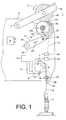
- FIG. 1is a simplified schematic side elevational view depicting the practice of the method of the present invention in a work station in a bobbin winding machine.
- FIG. 2is another simplified schematic side elevational view depicting the work station of the bobbin winding machine of FIG. 1 with the yarn placed in a splicing device.
- FIG. 1a work station in a bobbin winding machine is shown wherein the course of the yarn 2 between feeding bobbin 3 and take-up bobbin 4 has been interrupted at winding head 1 after a yarn cut on account of a yarn defect detected by cleaner 29 .
- the yarn interruptionis carried out by cutting device 34 .
- the path of travel of yarn 2 assumed during the normal winding operationhas therefore been shown in a broken line.
- Take-up bobbin 4is rotatably carried by bobbin holder 15 pivotably supported on machine frame 17 .
- Yarn gripper tube 5has caught the lower yarn 6 being unwound from feeding bobbin 3 via suction opening 7 and placed it into a yarn-end joining device, in this case designed as splicing device 8 .
- a drive(not shown for the sake of simplicity) has been activated by control device 9 via lead 5 a .
- the drivehas pivoted yarn gripper tube 5 out of its initial position 5 A shown in broken lines, in which suction opening 7 for catching the lower yarn 6 is in position 7 A in the path of travel of yarn 2 , into the position shown in FIG. 1 .
- Swivel joint 10about which yarn gripper tube 5 can be pivoted, is designed as a connection to vacuum line 11 that empties into suction conduit 12 .
- Suction conduit 12is connected to a central vacuum source of the bobbin winding machine.
- the lower yarn 6 held by suction opening 7 of yarn gripper tube 5runs in the position shown initially through open yarn tensioner 13 and then through splicing device 8 .
- a predetermined yarn length valueis stored in control device 9 .
- the predetermined yarn length valuecan be freely selected, taking into consideration the particular quality requirements for the yarn.
- Control device 9compares this stored length with the yarn length that had been wound onto take-up bobbin 4 since the restart of the winding process after the last yarn joinder.
- the impulsesare counted that are generated by sensor 33 and caused by the rotation of cogwheel 32 .
- the impulsesare fed via lead 33 a to control device 9 .
- Control device 9determines from these impulses the yarn length wound since the last yarn joinder and compares this yarn length with the stored length.
- take-up bobbin 4is driven in reverse in accordance with the present invention by friction roller 14 in an unwinding direction 21 until the last-occurring yarn joining location 38 has been unwound from the yarn body of take-up bobbin 4 .
- suction tube 22is positioned in front of the circumferential surface 20 of take-up bobbin 4 .
- Suction tube 22also communicates via swivel joint 24 and line 25 with suction conduit 12 .
- a valve(not shown) is regulated by control device 9 and suction tube 22 is loaded with a suction current.
- the suction currentis indicated by arrow 26 .
- Yarn end 27 lying on circumferential surface 20is drawn into suction tube 22 by suction and the unwinding process carried out in the manner in accordance with the present invention.
- the unwound yarn end 27has reached a length that is as long as the yarn length wound since the restart of the winding process after the last-occurring yarn joinder 38 or is longer than the latter by a predetermined amount, the unwinding of yarn end 27 is stopped.
- the predetermined amount added to the set lengthincreases the reliability that the last-occurring yarn joinder 38 is in the separated yarn section.
- Yarn end 27can be clamped in suction tube 22 by clamping device 30 before suction tube 22 pivots back into the initial position shown in FIG. 2, thereby placing the yarn into splicing device 8 .
- FIG. 2shows suction tube 22 returned into its initial position.
- Yarn 35 unwound from take-up bobbin 4has been placed into splicing device 8 .
- Yarn joining location 38 in yarn 36is thereby positioned above splicing device 8 , as viewed in the direction of yarn travel, and in no case below splicing device 8 in yarn 35 .
- Yarn 36is removed by suction after the separation via suction tube 22 .
- Yarn section 37 extending into yarn gripper tube 5is removed after the separation in yarn gripper tube 5 .
- the joinder of the yarn ends formed by the separationstakes place in the embodiment shown by pneumatic splicing. After the yarn joinder between the yarn from feeding bobbin 3 and the yarn from take-up bobbin 4 is successfully reestablished by splicing, the winding process is continued again.
- the method of the present inventionis used at the work station of a spinning bobbin winding machine.
- the spinning bobbin winding machinecan be, e.g., the type known from German Patent Publication DE 38 01 964 A1.
- the yarn sourceis formed by a spinning unit, such as a so-called spin box, and the spun yarn wound onto a take-up bobbin.
- the yarn joiningtakes place thereby by means of a joining or piecing process.
- the yarn joining location formed in this manneris designated as a joined yarn.
Landscapes
- Engineering & Computer Science (AREA)
- Quality & Reliability (AREA)
- Textile Engineering (AREA)
- Replacing, Conveying, And Pick-Finding For Filamentary Materials (AREA)
- Spinning Or Twisting Of Yarns (AREA)
Abstract
Description
Claims (5)
Applications Claiming Priority (3)
| Application Number | Priority Date | Filing Date | Title |
|---|---|---|---|
| DE10062479ADE10062479A1 (en) | 2000-12-14 | 2000-12-14 | Process for winding the running thread at a work station of a spinning or winding machine |
| DEDE10062479.0 | 2000-12-14 | ||
| DE10062479 | 2000-12-14 |
Publications (2)
| Publication Number | Publication Date |
|---|---|
| US20020074445A1 US20020074445A1 (en) | 2002-06-20 |
| US6637695B2true US6637695B2 (en) | 2003-10-28 |
Family
ID=7667244
Family Applications (1)
| Application Number | Title | Priority Date | Filing Date |
|---|---|---|---|
| US10/017,550Expired - LifetimeUS6637695B2 (en) | 2000-12-14 | 2001-12-14 | Method of winding a traveling yarn at a work station of a spinning bobbin winding machine or of a bobbin winding machine |
Country Status (4)
| Country | Link |
|---|---|
| US (1) | US6637695B2 (en) |
| EP (1) | EP1215154B1 (en) |
| CN (1) | CN1188334C (en) |
| DE (2) | DE10062479A1 (en) |
Cited By (1)
| Publication number | Priority date | Publication date | Assignee | Title |
|---|---|---|---|---|
| US20190023522A1 (en)* | 2017-07-19 | 2019-01-24 | Maschinenfabrik Rieter Ag | Method for Operating a Workstation of a Spinning Machine or Winder |
Families Citing this family (16)
| Publication number | Priority date | Publication date | Assignee | Title |
|---|---|---|---|---|
| DE10352429A1 (en)* | 2003-11-10 | 2005-06-23 | Saurer Gmbh & Co. Kg | yarn clearer |
| JP4120635B2 (en)* | 2004-11-19 | 2008-07-16 | 村田機械株式会社 | Textile machinery |
| CN1807728B (en)* | 2005-01-19 | 2010-11-10 | 上海题桥纺织染纱有限公司 | One-step completing method for chemical finishing of yarn cone before weaving |
| JP2009242095A (en)* | 2008-03-31 | 2009-10-22 | Murata Mach Ltd | Automatic winder |
| JP5007826B2 (en)* | 2008-03-31 | 2012-08-22 | 村田機械株式会社 | Yarn winding device and automatic winder equipped with this yarn winding device |
| JP2013052997A (en)* | 2011-09-06 | 2013-03-21 | Murata Machinery Ltd | Yarn winding machine |
| DE102012102576A1 (en)* | 2012-03-26 | 2013-09-26 | Maschinenfabrik Rieter Ag | Method for yarn monitoring |
| DE102013014195A1 (en)* | 2012-11-10 | 2014-05-15 | Saurer Germany Gmbh & Co. Kg | Elimination of a thread break when winding a thread on a cross-wound bobbin |
| US10246292B2 (en) | 2013-10-01 | 2019-04-02 | Maschinenfabrik Rieter Ag | Yarn clearer and spinning station, equipped therewith, of a spinning machine, and method for operating a spinning station |
| DE102015000570A1 (en)* | 2015-01-17 | 2016-07-21 | Saurer Germany Gmbh & Co. Kg | Method and device for evaluating the splices |
| DE102015013569A1 (en)* | 2015-10-20 | 2017-04-20 | Saurer Germany Gmbh & Co. Kg | A method of calibrating an upper thread detection process of work stations of a cross-wound textile machine |
| DE102016004563A1 (en)* | 2016-04-15 | 2017-10-19 | Oerlikon Textile Gmbh & Co. Kg | Device for winding a thread |
| CN106044361B (en)* | 2016-07-26 | 2019-01-11 | 西安坤蓝电子技术有限公司 | A kind of device for back and forth unwinding and winding for two revolution between centers conducting wires |
| CN108466869B (en)* | 2018-05-02 | 2024-01-19 | 浙江科技学院 | Shifting fork device of high-speed precise bobbin winder and operation method thereof |
| CN112204179B (en)* | 2018-05-28 | 2023-07-28 | 乌斯特技术股份公司 | Ring spinning system and method of operating the same |
| JP2022167816A (en)* | 2021-04-22 | 2022-11-04 | マスチネンファブリック ライター アーゲー | Method for replacing bobbin in spinning machine and spinning machine |
Citations (11)
| Publication number | Priority date | Publication date | Assignee | Title |
|---|---|---|---|---|
| DE2602235A1 (en) | 1976-01-22 | 1977-08-04 | Kenk Erhard | Yarn length measuring device - has wheel provided with speed measuring means producing signals applied to counter to wind bobbins with constant yarn length |
| DE3240486A1 (en) | 1981-11-02 | 1983-06-01 | Murata Kikai K.K., Kyoto | METHOD AND DEVICE FOR SEPARATING FAULTY OPERATING COILS IN A WINDING MACHINE |
| US4513921A (en)* | 1982-06-21 | 1985-04-30 | Aichi Spinning Co., Ltd. | Method and apparatus for detecting fluctuations of monitoring standard of thread-knotting monitor in auto-winder |
| DE3438962A1 (en) | 1984-10-24 | 1986-04-30 | A. Ott Gmbh, 8960 Kempten | THREAD WINDING MACHINE |
| US4817425A (en)* | 1986-04-25 | 1989-04-04 | Murata Kikai Kabushiki Kaisha | Yarn defect detecting method |
| DE3801964A1 (en) | 1988-01-23 | 1989-07-27 | Schlafhorst & Co W | METHOD AND DEVICE FOR RESTORING SPINNING OPERATION AFTER INTERRUPTION |
| DE3911505A1 (en) | 1989-04-08 | 1990-10-18 | Schlafhorst & Co W | Process and winding station for the production of a fault-free cross-wound bobbin |
| JPH05330740A (en) | 1992-06-01 | 1993-12-14 | Murata Mach Ltd | Automatic winder |
| EP0628509A1 (en) | 1993-05-12 | 1994-12-14 | Murata Kikai Kabushiki Kaisha | Taking-up method and apparatus for automatic winder |
| DE19640184A1 (en) | 1996-09-30 | 1998-04-02 | Schlafhorst & Co W | Yarn fault cleaning at bobbin rewinding station |
| DE10020665A1 (en) | 2000-04-27 | 2001-10-31 | Schlafhorst & Co W | Method for operating a textile machine producing cross-wound bobbins |
Family Cites Families (4)
| Publication number | Priority date | Publication date | Assignee | Title |
|---|---|---|---|---|
| US5787422A (en)* | 1996-01-11 | 1998-07-28 | Xerox Corporation | Method and apparatus for information accesss employing overlapping clusters |
| US5864855A (en)* | 1996-02-26 | 1999-01-26 | The United States Of America As Represented By The Secretary Of The Army | Parallel document clustering process |
| US5832182A (en)* | 1996-04-24 | 1998-11-03 | Wisconsin Alumni Research Foundation | Method and system for data clustering for very large databases |
| US6003029A (en)* | 1997-08-22 | 1999-12-14 | International Business Machines Corporation | Automatic subspace clustering of high dimensional data for data mining applications |
- 2000
- 2000-12-14DEDE10062479Apatent/DE10062479A1/ennot_activeWithdrawn
- 2001
- 2001-11-09DEDE50106511Tpatent/DE50106511D1/ennot_activeExpired - Lifetime
- 2001-11-09EPEP01126730Apatent/EP1215154B1/ennot_activeExpired - Lifetime
- 2001-12-14USUS10/017,550patent/US6637695B2/ennot_activeExpired - Lifetime
- 2001-12-14CNCNB011438118Apatent/CN1188334C/ennot_activeExpired - Fee Related
Patent Citations (16)
| Publication number | Priority date | Publication date | Assignee | Title |
|---|---|---|---|---|
| DE2602235A1 (en) | 1976-01-22 | 1977-08-04 | Kenk Erhard | Yarn length measuring device - has wheel provided with speed measuring means producing signals applied to counter to wind bobbins with constant yarn length |
| DE3240486A1 (en) | 1981-11-02 | 1983-06-01 | Murata Kikai K.K., Kyoto | METHOD AND DEVICE FOR SEPARATING FAULTY OPERATING COILS IN A WINDING MACHINE |
| US4513921A (en)* | 1982-06-21 | 1985-04-30 | Aichi Spinning Co., Ltd. | Method and apparatus for detecting fluctuations of monitoring standard of thread-knotting monitor in auto-winder |
| DE3438962A1 (en) | 1984-10-24 | 1986-04-30 | A. Ott Gmbh, 8960 Kempten | THREAD WINDING MACHINE |
| US4666096A (en) | 1984-10-24 | 1987-05-19 | A. Ott Gmbh | Thread spooler |
| US4817425A (en)* | 1986-04-25 | 1989-04-04 | Murata Kikai Kabushiki Kaisha | Yarn defect detecting method |
| DE3801964A1 (en) | 1988-01-23 | 1989-07-27 | Schlafhorst & Co W | METHOD AND DEVICE FOR RESTORING SPINNING OPERATION AFTER INTERRUPTION |
| US4920739A (en) | 1988-01-23 | 1990-05-01 | W. Schlafhorst & Co. | Method and apparatus for reestablishing the spinning operation |
| DE3911505A1 (en) | 1989-04-08 | 1990-10-18 | Schlafhorst & Co W | Process and winding station for the production of a fault-free cross-wound bobbin |
| JPH05330740A (en) | 1992-06-01 | 1993-12-14 | Murata Mach Ltd | Automatic winder |
| EP0628509A1 (en) | 1993-05-12 | 1994-12-14 | Murata Kikai Kabushiki Kaisha | Taking-up method and apparatus for automatic winder |
| US5531391A (en)* | 1993-05-12 | 1996-07-02 | Murata Kikai Kabushiki Kaisha | Method and apparatus for automatically inspecting and winding yarn, stopping and removing defective yarn and reconnecting and restarting winding after defective yarn is removed |
| DE19640184A1 (en) | 1996-09-30 | 1998-04-02 | Schlafhorst & Co W | Yarn fault cleaning at bobbin rewinding station |
| US5862660A (en) | 1996-09-30 | 1999-01-26 | W. Schlafhorst Ag & Co. | Method for removing yarn defects at a winding head of a bobbin winding machine |
| DE10020665A1 (en) | 2000-04-27 | 2001-10-31 | Schlafhorst & Co W | Method for operating a textile machine producing cross-wound bobbins |
| US20020023982A1 (en)* | 2000-04-27 | 2002-02-28 | Heribert Kargel | Method of operating a textile machine for producing cheeses |
Non-Patent Citations (4)
| Title |
|---|
| European Search Report. |
| German Search Report. |
| Patent Abstract of Japan 05 330 740 A1 Dec. 1993. |
| Publication H. Schwartz Entitled: Qualitätskontrolle durch Knotenzählung (Translation-Quality Control by Knot Counting) Apr. 1968. |
Cited By (2)
| Publication number | Priority date | Publication date | Assignee | Title |
|---|---|---|---|---|
| US20190023522A1 (en)* | 2017-07-19 | 2019-01-24 | Maschinenfabrik Rieter Ag | Method for Operating a Workstation of a Spinning Machine or Winder |
| US10829338B2 (en)* | 2017-07-19 | 2020-11-10 | Maschinenfabrik Rieter Ag | Method for operating a workstation of a spinning machine or winding machine |
Also Published As
| Publication number | Publication date |
|---|---|
| DE50106511D1 (en) | 2005-07-21 |
| EP1215154A2 (en) | 2002-06-19 |
| DE10062479A1 (en) | 2002-06-20 |
| US20020074445A1 (en) | 2002-06-20 |
| CN1358658A (en) | 2002-07-17 |
| CN1188334C (en) | 2005-02-09 |
| EP1215154A3 (en) | 2003-01-02 |
| EP1215154B1 (en) | 2005-06-15 |
Similar Documents
| Publication | Publication Date | Title |
|---|---|---|
| US6637695B2 (en) | Method of winding a traveling yarn at a work station of a spinning bobbin winding machine or of a bobbin winding machine | |
| US5862660A (en) | Method for removing yarn defects at a winding head of a bobbin winding machine | |
| JP2013063839A (en) | Yarn winding machine and yarn winding unit | |
| EP0101067B1 (en) | Method of piecing yarns in a spinning machine utilizing an air stream | |
| US6340129B1 (en) | Method for operating a workstation of a cheese-producing textile machine | |
| US5142856A (en) | Yarn piecing method for yarn spinning machine | |
| CN108286093B (en) | Spinning machine | |
| JP2016194187A (en) | Method for operating composite system comprising at least one ring spinning machine and at least one winding machine, and composite system | |
| EP2966023B1 (en) | Yarn winding machine and yarn winding method | |
| US6533211B2 (en) | Method of operating a textile machine for producing cheeses | |
| JP4529977B2 (en) | Core yarn spinning machine | |
| JPH06322622A (en) | Automatic winder | |
| JPS6047938B2 (en) | Yarn splicing method and device in open-end spinning unit | |
| CN111747233B (en) | Method for producing a piecing connection at a textile machine station and textile machine station | |
| EP0473212B1 (en) | Device and procedure for picking up and preparing the skein end for rejoining in an open-end spinning machine | |
| US4724665A (en) | Method of piecing yarn in the operation of an open end rotor spinning machine | |
| JPH0859086A (en) | Doffing method of automatic winder | |
| US10577728B2 (en) | Method for preparing a workstation for resumption of the spinning process on an air-jet spinning machine, and an air-jet spinning machine for performing the method | |
| US5279104A (en) | Process and device for the piecing of an open-end spinning device | |
| JPH04361629A (en) | Method for operating yarn piecing cart in apparatus for spinning cored yarn using elastic yarn as core yarn | |
| JP2024007744A (en) | Spinning machine, package forming method and package | |
| CN1133260A (en) | Method and equipment for removing defective yarn coiled on unwinding pipe | |
| JP2577009Y2 (en) | Automatic winder | |
| CN115467057A (en) | Spinning machine | |
| JP3414037B2 (en) | Automatic winder and method for removing defective yarn in automatic winder |
Legal Events
| Date | Code | Title | Description |
|---|---|---|---|
| AS | Assignment | Owner name:W.SCHLAFHORST AG & CO., GERMANY Free format text:ASSIGNMENT OF ASSIGNORS INTEREST;ASSIGNORS:OEHRL, WILHELM;HURTZ, BERT;DORNER, WOLFGANG;AND OTHERS;REEL/FRAME:012393/0435 Effective date:20011128 | |
| STCF | Information on status: patent grant | Free format text:PATENTED CASE | |
| FPAY | Fee payment | Year of fee payment:4 | |
| FPAY | Fee payment | Year of fee payment:8 | |
| AS | Assignment | Owner name:SAURER GMBH & CO. KG., GERMANY Free format text:CHANGE OF NAME;ASSIGNOR:W. SCHLAFHORST AG& CO.;REEL/FRAME:032141/0627 Effective date:20030731 | |
| AS | Assignment | Owner name:OERLIKON TEXTILE GMBH & CO. KG, GERMANY Free format text:CHANGE OF NAME;ASSIGNOR:SAURER GMBH & CO. KG;REEL/FRAME:032210/0498 Effective date:20070605 | |
| AS | Assignment | Owner name:SAURER GERMANY GMBH & CO. KG, GERMANY Free format text:ASSIGNMENT OF ASSIGNORS INTEREST;ASSIGNOR:OERLIKON TEXTILE GMBH & CO. KG;REEL/FRAME:033088/0448 Effective date:20140312 | |
| FPAY | Fee payment | Year of fee payment:12 | |
| AS | Assignment | Owner name:SAURER SPINNING SOLUTIONS GMBH & CO. KG, GERMANY Free format text:CHANGE OF NAME;ASSIGNOR:SAURER GERMANY GMBH & CO. KG;REEL/FRAME:048608/0716 Effective date:20180716 |