US6636821B2 - Output driver impedance calibration circuit - Google Patents
Output driver impedance calibration circuitDownload PDFInfo
- Publication number
- US6636821B2 US6636821B2US09/898,252US89825201AUS6636821B2US 6636821 B2US6636821 B2US 6636821B2US 89825201 AUS89825201 AUS 89825201AUS 6636821 B2US6636821 B2US 6636821B2
- Authority
- US
- United States
- Prior art keywords
- output
- circuit
- calibration
- output driver
- impedance
- Prior art date
- Legal status (The legal status is an assumption and is not a legal conclusion. Google has not performed a legal analysis and makes no representation as to the accuracy of the status listed.)
- Expired - Fee Related, expires
Links
- 230000000644propagated effectEffects0.000claimsdescription7
- 230000003213activating effectEffects0.000claims1
- 238000000034methodMethods0.000abstractdescription8
- 230000008901benefitEffects0.000description5
- 238000013461designMethods0.000description3
- PMAYSDOKQDPBDC-UHFFFAOYSA-N[3-hexadecanoyloxy-2-(2-phenylacetyl)oxypropyl] hexadecanoateChemical compoundCCCCCCCCCCCCCCCC(=O)OCC(COC(=O)CCCCCCCCCCCCCCC)OC(=O)CC1=CC=CC=C1PMAYSDOKQDPBDC-UHFFFAOYSA-N0.000description2
- 238000013459approachMethods0.000description2
- 238000004891communicationMethods0.000description2
- 238000010586diagramMethods0.000description2
- 238000005516engineering processMethods0.000description2
- 230000005540biological transmissionEffects0.000description1
- 230000007423decreaseEffects0.000description1
- 230000003247decreasing effectEffects0.000description1
- 230000000694effectsEffects0.000description1
- 230000001902propagating effectEffects0.000description1
- 238000012546transferMethods0.000description1
Images


Classifications
- H—ELECTRICITY
- H03—ELECTRONIC CIRCUITRY
- H03K—PULSE TECHNIQUE
- H03K19/00—Logic circuits, i.e. having at least two inputs acting on one output; Inverting circuits
- H03K19/0005—Modifications of input or output impedance
Definitions
- the present inventionrelates generally to an output driver impedance calibration circuit, and more particularly pertains to an output driver impedance calibration circuit which is used to make a plurality of I/O (input/output) off chip driver characteristics, for a plurality of output driver circuits, alike on the same chip within a tighter tolerance than is otherwise obtainable in the prior art.
- I/Oinput-output
- One significant characteristic of an I/O driver circuit that affects the input-output (I/O) signal integrityis its output impedance with respect to the signal line impedance at the system card level. Also, variations of both the I/O driver circuit impedance and the card impedance often become limiting factors in attaining high speed chip to chip communications with good signal integrity. In general, to maximize the transfer of power in a signal, the output impedance of an output driver circuit should match the input impedance of the transmission media connected to the output driver circuit, such as an electrical cable or another circuit or card.
- a further object of the subject inventionis the provision of an output driver impedance calibration circuit which can be used to make a plurality of I/O off chip driver characteristics, for a plurality of output driver circuits, alike on the same chip and within a tighter tolerance than is otherwise obtainable in the prior art.
- One chipmight typically have hundreds or thousands of output driver circuits.
- an external target impedance reference(it could be a multiple of the actual target output impedance);
- the I/O impedancecan typically be controlled to a +/ ⁇ 6.6% tolerance or better, and significantly benefits the signal integrity of the overall I/O interface.
- the calibration circuitis self contained and only requires core logic to toggle a UPDT (update) input at any time a recalibration is required to be updated, for example after a large change in temperature.
- the calibrationcan be performed for both the pull-down circuit and the pull-up circuit at one time, or could be split, and a direct calibration performed separately for each of the pull-down circuit and the pull-up circuit.
- the present inventiondiffers from the prior art in that the output device is not binarily weighted, and a logic core macro is used together with an I/O calibration cell to determine when the calibration process is completed, and is self contained in just the I/O calibration cell.
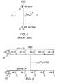
- FIG. 1illustrates a typical prior art CMOS output driver stage which comprises a PFET pull-up transistor base device, an NFET pull-down transistor base device, and an output resistor R leading to an output node PAD.
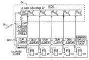
- FIG. 2shows a CMOS output driver stage pursuant to the present invention wherein a total of 5 devices have been added to each of the PFET pull-up transistor base device and the NFET pull-down transistor base device.
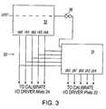
- FIG. 3is an impedance calibration circuit block diagram which illustrates the manner in which the present invention calibrates the impedance of each of the pull-up transistor devices and the pull-down transistor devices at a high level.
- FIG. 4illustrates details of the pull-down calibration circuit.
- FIG. 5illustrates details of the pull-up calibration circuit.
- FIG. 1illustrates a typical prior art CMOS output driver stage 10 such as may be incorporated, for example, in an ASIC chip.
- the CMOS output driver stageis connected between a chip power supply VDDO and ground, and comprises a PFET pull-up transistor output device 12 , an NFET pull-down transistor output device 14 , and an optional output resistor R leading to an output node PAD.
- the circuitIn order to obtain a calibrated output impedance for the CMOS output driver stage shown in FIG. 1, the circuit must be modified to accommodate the range of impedances desired over the process, voltage and temperature ranges of operation. Pursuant to the present invention, this is accomplished by adding additional calibration transistor devices to the output stage, as illustrated in FIG. 2, which are then used in a calibration process as described below. Each added transistor device reduces the output impedance of the output driver by an increment when it is turned on or activated, to provide a plurality of different incremental changes in the output impedance of the output driver as a selected number of the transistor devices are activated.
- FIG. 2shows a CMOS output driver stage 20 pursuant to the present invention wherein a total of 5 transistor devices have been added to each of the PFET pull-up transistor base device 16 in pull-up stage 22 and the NFET pull-down transistor base device 18 in pull-down stage 24 .
- Five additional transistor devicesare shown for illustrative purposes, but the actual number of added transistor devices could be more or less depending upon the requirements of the I/O interface. The sizes of these added devices are chosen based upon the desired increment of output impedance change as the adjacent devices are turned on or off. Every output driver on the chip that is calibrated requires an identical output stage as shown in FIG. 2 .
- FIG. 3is a block diagram of an impedance calibration circuit 30 which illustrates the manner in which the present invention calibrates the impedance of each of the pull-up transistor devices and the pull-down transistor devices at a high level.
- a UPDT (update) input signalis applied as an input to start the calibration process.
- This signalpropagates through a series of delay elements (see FIG. 4) in the pull-down calibration circuit 32 and turns on in sequence each of the transistor devices in the pull-down stage, and is then passed through an inverter 36 , and is then fed to the pull-up calibration circuit 34 where it also propagates through a series of delay elements (see FIG. 5) and turns on in sequence the transistor devices in the pull-up calibration circuit 34 .
- the state of calibrationis then available to all of the I/O driver Nfet and Pfet circuits on the same chip which require a calibrated output and have the same output impedance to within a desired tolerance.
- FIG. 4illustrates details of the pull-down calibration circuit 32 .
- a UPDT input signalis fed as an input to the circuit.
- An external precision resistor 40is used to provide a target impedance to the calibration circuit, and completes a circuit current path from the output power supply (VDDO) on the chip, through the external precision resistor 40 , through the conducting transistor devices in the output stage 24 on the chip, to the chip ground.
- the external precision resistor 40forms a voltage divider circuit with the conducting transistor devices in the output stage.
- a 1 ⁇ 4 sized output pull-down stageis used to match the 4 ⁇ target resistance, such that 4 output stages operate together to provide a desired 50 ⁇ output impedance.
- the input signal UPDTis propagated through the series of delay elements and turns on, in sequence, each of the output devices (base transistor device, and transistor devices having a gate receiving a signal of nb 0 , nb 1 , nb 2 , nb 3 , nb 4 ).
- the output voltage at the node PAD in FIG. 4changes in a monotonically decreasing (staircase) fashion, as illustrated by waveform 42 .
- This voltageis used as a first input to an analog comparator 44 whose second input is a calibrated voltage 46 , which is the voltage at which the 1 ⁇ 4 output pull-down stage is within a desired tolerance of the target external precision resistor.
- the gate voltage states (0 or 1)are captured in a first set of latches 47 , one for each output device gate.
- a calibration completed clocking circuit 48causes the states of the latches to be transferred to a second set of latches 49 , and are also transferred as outputs nb 0 , nb 1 , nb 2 , nb 3 , nb 4 to the gates of the transistor devices in all of the other calibrated output pull-down circuits 24 on the same chip.
- the pull-up calibration stage 34is shown in FIG. 5, and is calibrated in a fashion similar to the pull-down stage as, described previously. The differences are, as shown in FIGS. 3, 4 and 5 , the input signal to the PFET stage is inverted by inverter 36 in FIG. 3, and a calibrated 1 ⁇ 4 pull-down stage 50 , FIG. 5, is used as the target impedance, as opposed to the external precision resistor 40 , FIG. 4 .
- the internal node PADPis used as the first input to the comparator 52 , and a calibrated voltage 54 is provided as the second input to the comparator.
- the output voltage at the node PADP in FIG. 5changes in a monotonically increasing (staircase) fashion, as illustrated by waveform 56 .
- the latchingfunctions in the same manner as in the pull-down calibration circuit 32 .
- the calibrationcan be performed for both the pull-down circuit and the pull-up circuit at one time as shown in FIG. 3, or could be split, and a direct calibration performed separately for each of the pull-down circuit and the pull-up circuit, with each being provided with a separate UPDT input signal.
- the calibration circuitis self contained and only requires core logic to toggle a UPDT input at any time a recalibration is required, for example after a large change in temperature.
- the calibration circuitcan be split, and a direct calibration can be performed for each of the pull-down circuit and the pull-up circuit.
- the output stage designcan also take advantage of scaling the devices to obtain other impedances by using the calibrated output bits. For example, referring to FIG. 3, if the precision resistor is 200 ohms, then the bits calibrated to this on a 1 ⁇ 4-50 ohm output stage could be used to obtain another desired impedance by scaling the devices in a second design. For example, if the devices were scaled to provide half the impedance, then a 25 ohm calibrated output stage could be obtained. The disadvantage of this is it will be less accurate.
Landscapes
- Physics & Mathematics (AREA)
- Engineering & Computer Science (AREA)
- Computer Hardware Design (AREA)
- Computing Systems (AREA)
- General Engineering & Computer Science (AREA)
- Mathematical Physics (AREA)
- Logic Circuits (AREA)
Abstract
Description
Claims (14)
Priority Applications (1)
| Application Number | Priority Date | Filing Date | Title |
|---|---|---|---|
| US09/898,252US6636821B2 (en) | 2001-07-03 | 2001-07-03 | Output driver impedance calibration circuit |
Applications Claiming Priority (1)
| Application Number | Priority Date | Filing Date | Title |
|---|---|---|---|
| US09/898,252US6636821B2 (en) | 2001-07-03 | 2001-07-03 | Output driver impedance calibration circuit |
Publications (2)
| Publication Number | Publication Date |
|---|---|
| US20030009304A1 US20030009304A1 (en) | 2003-01-09 |
| US6636821B2true US6636821B2 (en) | 2003-10-21 |
Family
ID=25409162
Family Applications (1)
| Application Number | Title | Priority Date | Filing Date |
|---|---|---|---|
| US09/898,252Expired - Fee RelatedUS6636821B2 (en) | 2001-07-03 | 2001-07-03 | Output driver impedance calibration circuit |
Country Status (1)
| Country | Link |
|---|---|
| US (1) | US6636821B2 (en) |
Cited By (18)
| Publication number | Priority date | Publication date | Assignee | Title |
|---|---|---|---|---|
| US20030056128A1 (en)* | 2001-09-20 | 2003-03-20 | Leddige Michael W. | Apparatus and method for a selectable Ron driver impedance |
| US20050093569A1 (en)* | 2003-10-31 | 2005-05-05 | Aaron Nygren | Pseudodynamic off-chip driver calibration |
| US20050104624A1 (en)* | 2003-11-14 | 2005-05-19 | Zumkehr John F. | Internal voltage reference for memory interface |
| US20060061387A1 (en)* | 2004-09-14 | 2006-03-23 | Infineon Technologies Ag | Calibration circuit for a driver control circuit, and driver control circuit |
| US7218155B1 (en)* | 2005-01-20 | 2007-05-15 | Altera Corporation | Techniques for controlling on-chip termination resistance using voltage range detection |
| US7221193B1 (en)* | 2005-01-20 | 2007-05-22 | Altera Corporation | On-chip termination with calibrated driver strength |
| US20070268039A1 (en)* | 2006-05-17 | 2007-11-22 | Sony Corporation | Programmable impedance control circuit calibrated at voh, vol level |
| US20080112246A1 (en)* | 2006-11-14 | 2008-05-15 | Micron Technology, Inc. | Digital calibration circuits, devices and systems including same, and methods of operation |
| US20090164165A1 (en)* | 2007-12-19 | 2009-06-25 | Russell Homer | Integrated circuit including calibration circuit |
| US20110241653A1 (en)* | 2010-03-31 | 2011-10-06 | Hynix Semiconductor Inc. | Impedance calibration apparatus of semiconductor integrated circuit |
| US8319520B2 (en) | 2010-04-01 | 2012-11-27 | SK Hynix Inc. | On-die termination circuit |
| US8395411B2 (en) | 2010-10-08 | 2013-03-12 | Qualcomm Incorporated | Constant impedance line driver with digitally controlled edge rate |
| USRE44617E1 (en)* | 2006-08-24 | 2013-12-03 | Hynix Semiconductor Inc. | On-die termination device |
| US20130335114A1 (en)* | 2012-06-18 | 2013-12-19 | International Business Machines Corporation | Implementing linearly weighted thermal coded i/o driver output stage calibration |
| US9236863B2 (en) | 2013-01-02 | 2016-01-12 | Globalfoundries Inc. | Compensated impedance calibration circuit |
| US9543952B2 (en) | 2013-10-29 | 2017-01-10 | Samsung Electronics Co., Ltd. | Semiconductor memory device and a method of operating the same |
| US9748956B2 (en) | 2015-01-13 | 2017-08-29 | Samsung Electronics Co., Ltd. | Integrated circuit and storage device including the same |
| US10333497B1 (en) | 2018-04-04 | 2019-06-25 | Globalfoundries Inc. | Calibration devices for I/O driver circuits having switches biased differently for different temperatures |
Families Citing this family (11)
| Publication number | Priority date | Publication date | Assignee | Title |
|---|---|---|---|---|
| KR100605590B1 (en)* | 2004-05-10 | 2006-07-31 | 주식회사 하이닉스반도체 | Semiconductor memory device that can adjust impedance of data output driver |
| US20070005519A1 (en)* | 2005-06-20 | 2007-01-04 | Ravi Gupta | Systems and methods for utility meter demand data collection |
| TWI400455B (en)* | 2009-09-30 | 2013-07-01 | Mstar Semiconductor Inc | Method for calibrating input and output circuits and related devices |
| WO2012158392A2 (en)* | 2011-05-17 | 2012-11-22 | Rambus Inc. | Memory system using asymmetric source-synchronous clocking |
| US10277435B2 (en) | 2017-08-07 | 2019-04-30 | Micron Technology, Inc. | Method to vertically align multi-level cells |
| US10530617B2 (en) | 2017-08-07 | 2020-01-07 | Micron Technology, Inc. | Programmable channel equalization for multi-level signaling |
| US10425260B2 (en) | 2017-08-07 | 2019-09-24 | Micron Technology, Inc. | Multi-level signaling in memory with wide system interface |
| US10128842B1 (en)* | 2018-03-23 | 2018-11-13 | Micron Technology, Inc. | Output impedance calibration for signaling |
| US10347325B1 (en)* | 2018-06-29 | 2019-07-09 | Realtek Semiconductor Corporation | DDR4 memory I/O driver |
| US11024353B1 (en)* | 2020-04-24 | 2021-06-01 | Western Digital Technologies, Inc. | Mechanism to improve driver capability with fine tuned calibration resistor |
| CN116418334B (en)* | 2023-03-28 | 2024-04-02 | 成都电科星拓科技有限公司 | A method and device for generating a mirrored output stage to adjust output impedance matching |
Citations (13)
| Publication number | Priority date | Publication date | Assignee | Title |
|---|---|---|---|---|
| US5559441A (en) | 1995-04-19 | 1996-09-24 | Hewlett-Packard Company | Transmission line driver with self adjusting output impedance |
| US5657456A (en) | 1993-06-18 | 1997-08-12 | Digital Equipment Corporation | Semiconductor process power supply voltage and temperature compensated integrated system bus driver rise and fall time |
| US6031385A (en) | 1997-03-24 | 2000-02-29 | Intel Corporation | Method and apparatus for testing compensated buffer circuits |
| US6051995A (en) | 1998-09-11 | 2000-04-18 | Sharp Electronics Corporation | Constant impedance, low noise CMOS buffer |
| US6064224A (en) | 1998-07-31 | 2000-05-16 | Hewlett--Packard Company | Calibration sharing for CMOS output driver |
| US6118310A (en)* | 1998-11-04 | 2000-09-12 | Agilent Technologies | Digitally controlled output driver and method for impedance matching |
| US6133749A (en)* | 1999-01-04 | 2000-10-17 | International Business Machines Corporation | Variable impedance output driver circuit using analog biases to match driver output impedance to load input impedance |
| US6268750B1 (en)* | 2000-01-11 | 2001-07-31 | Agilent Technologies, Inc. | Flattened resistance response for an electrical output driver |
| US6281687B1 (en)* | 1999-06-09 | 2001-08-28 | Agilent Technologies | Off-chip process, voltage, temperature, compensation resistor sharing |
| US6333639B1 (en)* | 2000-06-23 | 2001-12-25 | Micron Technology, Inc. | Method and apparatus for independent output driver calibration |
| US6448811B1 (en)* | 2001-04-02 | 2002-09-10 | Intel Corporation | Integrated circuit current reference |
| US6456124B1 (en)* | 1999-08-09 | 2002-09-24 | Samsung Electronics Co., Ltd. | Method and apparatus for controlling impedance of an off-chip driver circuit |
| US6509757B1 (en)* | 2001-08-02 | 2003-01-21 | Agilent Technologies, Inc. | Binary weighted thermometer code for PVT controlled output drivers |
- 2001
- 2001-07-03USUS09/898,252patent/US6636821B2/ennot_activeExpired - Fee Related
Patent Citations (13)
| Publication number | Priority date | Publication date | Assignee | Title |
|---|---|---|---|---|
| US5657456A (en) | 1993-06-18 | 1997-08-12 | Digital Equipment Corporation | Semiconductor process power supply voltage and temperature compensated integrated system bus driver rise and fall time |
| US5559441A (en) | 1995-04-19 | 1996-09-24 | Hewlett-Packard Company | Transmission line driver with self adjusting output impedance |
| US6031385A (en) | 1997-03-24 | 2000-02-29 | Intel Corporation | Method and apparatus for testing compensated buffer circuits |
| US6064224A (en) | 1998-07-31 | 2000-05-16 | Hewlett--Packard Company | Calibration sharing for CMOS output driver |
| US6051995A (en) | 1998-09-11 | 2000-04-18 | Sharp Electronics Corporation | Constant impedance, low noise CMOS buffer |
| US6118310A (en)* | 1998-11-04 | 2000-09-12 | Agilent Technologies | Digitally controlled output driver and method for impedance matching |
| US6133749A (en)* | 1999-01-04 | 2000-10-17 | International Business Machines Corporation | Variable impedance output driver circuit using analog biases to match driver output impedance to load input impedance |
| US6281687B1 (en)* | 1999-06-09 | 2001-08-28 | Agilent Technologies | Off-chip process, voltage, temperature, compensation resistor sharing |
| US6456124B1 (en)* | 1999-08-09 | 2002-09-24 | Samsung Electronics Co., Ltd. | Method and apparatus for controlling impedance of an off-chip driver circuit |
| US6268750B1 (en)* | 2000-01-11 | 2001-07-31 | Agilent Technologies, Inc. | Flattened resistance response for an electrical output driver |
| US6333639B1 (en)* | 2000-06-23 | 2001-12-25 | Micron Technology, Inc. | Method and apparatus for independent output driver calibration |
| US6448811B1 (en)* | 2001-04-02 | 2002-09-10 | Intel Corporation | Integrated circuit current reference |
| US6509757B1 (en)* | 2001-08-02 | 2003-01-21 | Agilent Technologies, Inc. | Binary weighted thermometer code for PVT controlled output drivers |
Cited By (31)
| Publication number | Priority date | Publication date | Assignee | Title |
|---|---|---|---|---|
| US20030056128A1 (en)* | 2001-09-20 | 2003-03-20 | Leddige Michael W. | Apparatus and method for a selectable Ron driver impedance |
| CN100350746C (en)* | 2003-10-31 | 2007-11-21 | 因芬尼昂技术股份公司 | Pseudodynamic off-chip driver calibration |
| US20050093569A1 (en)* | 2003-10-31 | 2005-05-05 | Aaron Nygren | Pseudodynamic off-chip driver calibration |
| US7304495B2 (en) | 2003-10-31 | 2007-12-04 | Infineon Technologies Ag | Pseudodynamic off-chip driver calibration |
| US20050104624A1 (en)* | 2003-11-14 | 2005-05-19 | Zumkehr John F. | Internal voltage reference for memory interface |
| US7095245B2 (en)* | 2003-11-14 | 2006-08-22 | Intel Corporation | Internal voltage reference for memory interface |
| US20060061387A1 (en)* | 2004-09-14 | 2006-03-23 | Infineon Technologies Ag | Calibration circuit for a driver control circuit, and driver control circuit |
| US7253656B2 (en) | 2004-09-14 | 2007-08-07 | Infineon Technologies | Calibration circuit for a driver control circuit, and driver control circuit |
| DE102004044422B3 (en)* | 2004-09-14 | 2006-03-30 | Infineon Technologies Ag | Calibration circuit for a driver control circuit and driver control circuit |
| US7221193B1 (en)* | 2005-01-20 | 2007-05-22 | Altera Corporation | On-chip termination with calibrated driver strength |
| US7218155B1 (en)* | 2005-01-20 | 2007-05-15 | Altera Corporation | Techniques for controlling on-chip termination resistance using voltage range detection |
| US20070268039A1 (en)* | 2006-05-17 | 2007-11-22 | Sony Corporation | Programmable impedance control circuit calibrated at voh, vol level |
| US7312629B2 (en) | 2006-05-17 | 2007-12-25 | Sony Corporation | Programmable impedance control circuit calibrated at Voh, Vol level |
| USRE44617E1 (en)* | 2006-08-24 | 2013-12-03 | Hynix Semiconductor Inc. | On-die termination device |
| US7459930B2 (en) | 2006-11-14 | 2008-12-02 | Micron Technology, Inc. | Digital calibration circuits, devices and systems including same, and methods of operation |
| US20080112246A1 (en)* | 2006-11-14 | 2008-05-15 | Micron Technology, Inc. | Digital calibration circuits, devices and systems including same, and methods of operation |
| US7821291B2 (en) | 2006-11-14 | 2010-10-26 | Micron Technology, Inc. | Digital calibration circuits, devices and systems including same, and methods of operation |
| US20090066368A1 (en)* | 2006-11-14 | 2009-03-12 | Shizhong Mei | Digital calibration circuits, devices and systems including same, and methods of operation |
| US20090164165A1 (en)* | 2007-12-19 | 2009-06-25 | Russell Homer | Integrated circuit including calibration circuit |
| US7991573B2 (en) | 2007-12-19 | 2011-08-02 | Qimonda Ag | Integrated circuit including calibration circuit |
| US9374088B2 (en)* | 2010-03-31 | 2016-06-21 | SK Hynix Inc. | Impedance calibration apparatus of semiconductor integrated circuit |
| US20110241653A1 (en)* | 2010-03-31 | 2011-10-06 | Hynix Semiconductor Inc. | Impedance calibration apparatus of semiconductor integrated circuit |
| US8319520B2 (en) | 2010-04-01 | 2012-11-27 | SK Hynix Inc. | On-die termination circuit |
| US8395411B2 (en) | 2010-10-08 | 2013-03-12 | Qualcomm Incorporated | Constant impedance line driver with digitally controlled edge rate |
| US20130335114A1 (en)* | 2012-06-18 | 2013-12-19 | International Business Machines Corporation | Implementing linearly weighted thermal coded i/o driver output stage calibration |
| US8766663B2 (en)* | 2012-06-18 | 2014-07-01 | International Business Machines Corporation | Implementing linearly weighted thermal coded I/O driver output stage calibration |
| US9236863B2 (en) | 2013-01-02 | 2016-01-12 | Globalfoundries Inc. | Compensated impedance calibration circuit |
| US9270268B2 (en) | 2013-01-02 | 2016-02-23 | International Business Machines Corporation | Compensated impedance calibration circuit |
| US9543952B2 (en) | 2013-10-29 | 2017-01-10 | Samsung Electronics Co., Ltd. | Semiconductor memory device and a method of operating the same |
| US9748956B2 (en) | 2015-01-13 | 2017-08-29 | Samsung Electronics Co., Ltd. | Integrated circuit and storage device including the same |
| US10333497B1 (en) | 2018-04-04 | 2019-06-25 | Globalfoundries Inc. | Calibration devices for I/O driver circuits having switches biased differently for different temperatures |
Also Published As
| Publication number | Publication date |
|---|---|
| US20030009304A1 (en) | 2003-01-09 |
Similar Documents
| Publication | Publication Date | Title |
|---|---|---|
| US6636821B2 (en) | Output driver impedance calibration circuit | |
| US8004308B2 (en) | Techniques for providing calibrated on-chip termination impedance | |
| US7884638B1 (en) | Techniques for providing calibrated on-chip termination impedance | |
| US7034567B2 (en) | Semiconductor devices with reference voltage generators and termination circuits configured to reduce termination mismatch | |
| US7372295B1 (en) | Techniques for calibrating on-chip termination impedances | |
| US6133749A (en) | Variable impedance output driver circuit using analog biases to match driver output impedance to load input impedance | |
| US7698802B2 (en) | Method for manufacturing a calibration device | |
| US7269043B2 (en) | Memory module and impedance calibration method of semiconductor memory device | |
| US6894529B1 (en) | Impedance-matched output driver circuits having linear characteristics and enhanced coarse and fine tuning control | |
| US7944232B2 (en) | Output circuit having variable output voltage swing level | |
| US6628223B2 (en) | Resistance changeable device for data transmission system | |
| US6812735B1 (en) | Multiple value self-calibrated termination resistors | |
| US7382153B2 (en) | On-chip resistor calibration for line termination | |
| CN112187214B (en) | IO impedance calibration circuit and method of FPGA | |
| JP2008135925A (en) | Calibration circuit | |
| EP1041718B1 (en) | A low power adjustable input threshold circuit | |
| US7148720B2 (en) | Impedance matching circuit and method | |
| US7084662B1 (en) | Variable impedance output driver | |
| US6922074B2 (en) | ASIC architecture for active-compensation of a programmable impedance I/O | |
| US20060170478A1 (en) | Delay circuit for semiconductor device | |
| US6603331B1 (en) | Low-voltage non-degenerative transmitter circuit | |
| US12354685B2 (en) | Impedance adjusting circuit and impedance adjusting method for zero quotient calibration | |
| CN106330143B (en) | Duty-ratio calibrating circuit | |
| JPH06260884A (en) | Semiconductor integrated circuit | |
| KR100313499B1 (en) | Sense amplifier reference voltage variableness circuit |
Legal Events
| Date | Code | Title | Description |
|---|---|---|---|
| AS | Assignment | Owner name:INTERNATIONAL BUSINESS MACHINES CORPORATION, NEW Y Free format text:ASSIGNMENT OF ASSIGNORS INTEREST;ASSIGNOR:LAWSON, WILLIAM F.;REEL/FRAME:011974/0301 Effective date:20010702 | |
| FEPP | Fee payment procedure | Free format text:PAYOR NUMBER ASSIGNED (ORIGINAL EVENT CODE: ASPN); ENTITY STATUS OF PATENT OWNER: LARGE ENTITY | |
| FPAY | Fee payment | Year of fee payment:4 | |
| REMI | Maintenance fee reminder mailed | ||
| FPAY | Fee payment | Year of fee payment:8 | |
| SULP | Surcharge for late payment | Year of fee payment:7 | |
| AS | Assignment | Owner name:GOOGLE INC., CALIFORNIA Free format text:ASSIGNMENT OF ASSIGNORS INTEREST;ASSIGNOR:INTERNATIONAL BUSINESS MACHINES CORPORATION;REEL/FRAME:026664/0866 Effective date:20110503 | |
| REMI | Maintenance fee reminder mailed | ||
| LAPS | Lapse for failure to pay maintenance fees | ||
| STCH | Information on status: patent discontinuation | Free format text:PATENT EXPIRED DUE TO NONPAYMENT OF MAINTENANCE FEES UNDER 37 CFR 1.362 | |
| FP | Lapsed due to failure to pay maintenance fee | Effective date:20151021 | |
| AS | Assignment | Owner name:GOOGLE LLC, CALIFORNIA Free format text:CHANGE OF NAME;ASSIGNOR:GOOGLE INC.;REEL/FRAME:044144/0001 Effective date:20170929 | |
| AS | Assignment | Owner name:GOOGLE LLC, CALIFORNIA Free format text:CORRECTIVE ASSIGNMENT TO CORRECT THE THE REMOVAL OF THE INCORRECTLY RECORDED APPLICATION NUMBERS 14/149802 AND 15/419313 PREVIOUSLY RECORDED AT REEL: 44144 FRAME: 1. ASSIGNOR(S) HEREBY CONFIRMS THE CHANGE OF NAME;ASSIGNOR:GOOGLE INC.;REEL/FRAME:068092/0502 Effective date:20170929 |