US6636755B2 - Method and apparatus for obtaining an optical tomographic image of a sentinel lymph node - Google Patents
Method and apparatus for obtaining an optical tomographic image of a sentinel lymph nodeDownload PDFInfo
- Publication number
- US6636755B2 US6636755B2US09/962,195US96219501AUS6636755B2US 6636755 B2US6636755 B2US 6636755B2US 96219501 AUS96219501 AUS 96219501AUS 6636755 B2US6636755 B2US 6636755B2
- Authority
- US
- United States
- Prior art keywords
- light
- lymph node
- sentinel lymph
- image
- signal
- Prior art date
- Legal status (The legal status is an assumption and is not a legal conclusion. Google has not performed a legal analysis and makes no representation as to the accuracy of the status listed.)
- Expired - Fee Related, expires
Links
- 210000005005sentinel lymph nodeAnatomy0.000titleclaimsabstractdescription174
- 230000003287optical effectEffects0.000titleclaimsabstractdescription89
- 238000000034methodMethods0.000titleclaimsdescription35
- 210000001165lymph nodeAnatomy0.000claimsabstractdescription30
- 239000003086colorantSubstances0.000claimsabstractdescription25
- 230000005284excitationEffects0.000claimsdescription46
- 238000001514detection methodMethods0.000claimsdescription17
- 238000002347injectionMethods0.000claimsdescription2
- 239000007924injectionSubstances0.000claimsdescription2
- 230000001678irradiating effectEffects0.000claimsdescription2
- 238000001727in vivoMethods0.000claims1
- 239000012466permeateSubstances0.000claims1
- 239000000758substrateSubstances0.000claims1
- 239000000835fiberSubstances0.000abstractdescription56
- 206010028980NeoplasmDiseases0.000abstractdescription21
- 201000011510cancerDiseases0.000abstractdescription16
- 238000012014optical coherence tomographyMethods0.000abstractdescription15
- 230000007170pathologyEffects0.000abstractdescription9
- 230000005855radiationEffects0.000abstractdescription9
- 239000000523sampleSubstances0.000abstractdescription9
- 230000001413cellular effectEffects0.000abstractdescription7
- 238000012360testing methodMethods0.000abstractdescription7
- 238000001356surgical procedureMethods0.000description24
- 238000005259measurementMethods0.000description18
- 238000012545processingMethods0.000description16
- 201000010099diseaseDiseases0.000description14
- 208000037265diseases, disorders, signs and symptomsDiseases0.000description14
- 239000013307optical fiberSubstances0.000description14
- 210000001519tissueAnatomy0.000description13
- 238000003780insertionMethods0.000description10
- 230000037431insertionEffects0.000description10
- 239000004065semiconductorSubstances0.000description8
- MOFVSTNWEDAEEK-UHFFFAOYSA-Mindocyanine greenChemical compound[Na+].[O-]S(=O)(=O)CCCCN1C2=CC=C3C=CC=CC3=C2C(C)(C)C1=CC=CC=CC=CC1=[N+](CCCCS([O-])(=O)=O)C2=CC=C(C=CC=C3)C3=C2C1(C)CMOFVSTNWEDAEEK-UHFFFAOYSA-M0.000description6
- 229960004657indocyanine greenDrugs0.000description6
- 239000000038blue colorantSubstances0.000description4
- 238000001228spectrumMethods0.000description4
- 206010006187Breast cancerDiseases0.000description3
- 208000026310Breast neoplasmDiseases0.000description3
- 206010027476MetastasesDiseases0.000description3
- 210000004027cellAnatomy0.000description3
- 230000008878couplingEffects0.000description3
- 238000010168coupling processMethods0.000description3
- 238000005859coupling reactionMethods0.000description3
- 210000001035gastrointestinal tractAnatomy0.000description3
- 238000005286illuminationMethods0.000description3
- 210000002751lymphAnatomy0.000description3
- 230000009401metastasisEffects0.000description3
- 239000000700radioactive tracerSubstances0.000description3
- ANRHNWWPFJCPAZ-UHFFFAOYSA-MthionineChemical compound[Cl-].C1=CC(N)=CC2=[S+]C3=CC(N)=CC=C3N=C21ANRHNWWPFJCPAZ-UHFFFAOYSA-M0.000description3
- 230000003321amplificationEffects0.000description2
- 230000008901benefitEffects0.000description2
- 230000008859changeEffects0.000description2
- 230000001419dependent effectEffects0.000description2
- 239000006185dispersionSubstances0.000description2
- 238000003199nucleic acid amplification methodMethods0.000description2
- 230000008569processEffects0.000description2
- 238000005070samplingMethods0.000description2
- 230000003595spectral effectEffects0.000description2
- 238000002834transmittanceMethods0.000description2
- 238000000862absorption spectrumMethods0.000description1
- 210000000577adipose tissueAnatomy0.000description1
- 210000004204blood vesselAnatomy0.000description1
- 230000037396body weightEffects0.000description1
- 239000002131composite materialSubstances0.000description1
- 238000007796conventional methodMethods0.000description1
- 238000003745diagnosisMethods0.000description1
- 230000004069differentiationEffects0.000description1
- 230000000694effectsEffects0.000description1
- 230000006870functionEffects0.000description1
- 239000003365glass fiberSubstances0.000description1
- 230000000977initiatory effectEffects0.000description1
- 238000004321preservationMethods0.000description1
- 102000004169proteins and genesHuman genes0.000description1
- 108090000623proteins and genesProteins0.000description1
- 238000011160researchMethods0.000description1
- 230000004044responseEffects0.000description1
- 230000007704transitionEffects0.000description1
- 210000004881tumor cellAnatomy0.000description1
Images


Classifications
- A—HUMAN NECESSITIES
- A61—MEDICAL OR VETERINARY SCIENCE; HYGIENE
- A61K—PREPARATIONS FOR MEDICAL, DENTAL OR TOILETRY PURPOSES
- A61K49/00—Preparations for testing in vivo
- A61K49/001—Preparation for luminescence or biological staining
- A61K49/0013—Luminescence
- A61K49/0017—Fluorescence in vivo
- A61K49/0019—Fluorescence in vivo characterised by the fluorescent group, e.g. oligomeric, polymeric or dendritic molecules
- A61K49/0021—Fluorescence in vivo characterised by the fluorescent group, e.g. oligomeric, polymeric or dendritic molecules the fluorescent group being a small organic molecule
- A61K49/0032—Methine dyes, e.g. cyanine dyes
- A61K49/0034—Indocyanine green, i.e. ICG, cardiogreen
- A—HUMAN NECESSITIES
- A61—MEDICAL OR VETERINARY SCIENCE; HYGIENE
- A61B—DIAGNOSIS; SURGERY; IDENTIFICATION
- A61B5/00—Measuring for diagnostic purposes; Identification of persons
- A61B5/0059—Measuring for diagnostic purposes; Identification of persons using light, e.g. diagnosis by transillumination, diascopy, fluorescence
- A61B5/0062—Arrangements for scanning
- A61B5/0066—Optical coherence imaging
- A—HUMAN NECESSITIES
- A61—MEDICAL OR VETERINARY SCIENCE; HYGIENE
- A61B—DIAGNOSIS; SURGERY; IDENTIFICATION
- A61B5/00—Measuring for diagnostic purposes; Identification of persons
- A61B5/0059—Measuring for diagnostic purposes; Identification of persons using light, e.g. diagnosis by transillumination, diascopy, fluorescence
- A61B5/0071—Measuring for diagnostic purposes; Identification of persons using light, e.g. diagnosis by transillumination, diascopy, fluorescence by measuring fluorescence emission
- A—HUMAN NECESSITIES
- A61—MEDICAL OR VETERINARY SCIENCE; HYGIENE
- A61B—DIAGNOSIS; SURGERY; IDENTIFICATION
- A61B5/00—Measuring for diagnostic purposes; Identification of persons
- A61B5/41—Detecting, measuring or recording for evaluating the immune or lymphatic systems
- A61B5/414—Evaluating particular organs or parts of the immune or lymphatic systems
- A61B5/418—Evaluating particular organs or parts of the immune or lymphatic systems lymph vessels, ducts or nodes
- G—PHYSICS
- G01—MEASURING; TESTING
- G01B—MEASURING LENGTH, THICKNESS OR SIMILAR LINEAR DIMENSIONS; MEASURING ANGLES; MEASURING AREAS; MEASURING IRREGULARITIES OF SURFACES OR CONTOURS
- G01B9/00—Measuring instruments characterised by the use of optical techniques
- G01B9/02—Interferometers
- G01B9/02001—Interferometers characterised by controlling or generating intrinsic radiation properties
- G01B9/02002—Interferometers characterised by controlling or generating intrinsic radiation properties using two or more frequencies
- G01B9/02003—Interferometers characterised by controlling or generating intrinsic radiation properties using two or more frequencies using beat frequencies
- G—PHYSICS
- G01—MEASURING; TESTING
- G01B—MEASURING LENGTH, THICKNESS OR SIMILAR LINEAR DIMENSIONS; MEASURING ANGLES; MEASURING AREAS; MEASURING IRREGULARITIES OF SURFACES OR CONTOURS
- G01B9/00—Measuring instruments characterised by the use of optical techniques
- G01B9/02—Interferometers
- G01B9/02015—Interferometers characterised by the beam path configuration
- G01B9/02029—Combination with non-interferometric systems, i.e. for measuring the object
- G01B9/0203—With imaging systems
- G—PHYSICS
- G01—MEASURING; TESTING
- G01B—MEASURING LENGTH, THICKNESS OR SIMILAR LINEAR DIMENSIONS; MEASURING ANGLES; MEASURING AREAS; MEASURING IRREGULARITIES OF SURFACES OR CONTOURS
- G01B9/00—Measuring instruments characterised by the use of optical techniques
- G01B9/02—Interferometers
- G01B9/02015—Interferometers characterised by the beam path configuration
- G01B9/02029—Combination with non-interferometric systems, i.e. for measuring the object
- G01B9/02031—With non-optical systems, e.g. tactile
- G—PHYSICS
- G01—MEASURING; TESTING
- G01B—MEASURING LENGTH, THICKNESS OR SIMILAR LINEAR DIMENSIONS; MEASURING ANGLES; MEASURING AREAS; MEASURING IRREGULARITIES OF SURFACES OR CONTOURS
- G01B9/00—Measuring instruments characterised by the use of optical techniques
- G01B9/02—Interferometers
- G01B9/0209—Low-coherence interferometers
- G01B9/02091—Tomographic interferometers, e.g. based on optical coherence
Definitions
- the present inventionrelates in general to a method and apparatus for obtaining an optical tomographic image of a sentinel lymph node, and in particular, to detecting the sentinel lymph node, into which tumor cells first enter the lymph system from the primary nidus of a tumor, and obtaining an optical tomographic image of the sentinel lymph node.
- cancerous and other diseased tissuesare frequently surgically removed in the early stages of a disease.
- the objective of early surgical removal of cancerous tissueis the complete arresting of the disease, and frequently, in addition to the diseased tissue, a plurality of lymph nodes in the area surrounding the diseased tissue, from which there is a suspected danger of metastasis of the disease, are also removed.
- a test for pathologyis performed on the excised lymph nodes to confirm whether or not the disease has metastasized thereto, and the course of post-surgical treatment is determined.
- the rate of metastasis of the disease to lymph nodesis 20 percent; for the 80 percent of the patients in whom the disease has not metastasized to the lymph nodes, the removal thereof is unnecessary.
- lymph nodesFor cases in which cancer has metastasized to lymph nodes, it has become clear, in light of recent research, that it does not metastasize randomly, but is metastasize through the lymph system to the lymph nodes according to a set pattern.
- the first lymph node into which cancer cells enter from the primary nidus of a canceris called a sentinel lymph node; it is held that for cases in which cancer has metastasized to the lymph nodes, the cancer has definitely metastasized to a sentinel lymph node.
- lymph nodesFor cases in which the cancer is determined not to have metastasized to the lymph nodes, it is unnecessary to remove the remaining lymph nodes. For cases in which the cancer is found to have metastasized to the lymph nodes, depending upon the conditions, a plurality of lymph nodes are surgically removed from the vicinity surrounding the diseased tissue.
- this type of surgeryis not limited to breast cancer, but can be employed in conjunction with open gastrointestinal tract surgery or surgical procedures utilizing a laparoscope.
- One conventional method of detecting the lymph nodeis the colorant method, employing a blue colorant.
- a blue colorantis locally injected, endermically or by use of an endoscope, into the vicinity surrounding the diseased area directly preceding the performance of cancer removal surgery; the sentinel lymph node dyed by the blue colorant is visually detected.
- Another known methodis the RI method, wherein a radioisotope is employed as a tracer.
- a radioisotopeis locally injected, endermically or by use of an endoscope, on the day prior to surgery into the vicinity surrounding the diseased area.
- the injected radioisotopeadvances from the position at which it was injected towards the lymph nodes and stays for a set duration at the sentinel lymph node. A few hours after the radioisotope is injected a lymphosynthography is performed, and the approximate position is marked.
- the marked positionis cut open, and employing a gamma-probe, the gamma radiation emitted by the lymph nodes in the vicinity of the opened position is detected; the lymph node emitting the most gamma radiation is detected as the sentinel lymph node.
- fluorescent colorant methods employing fluorescent colorantshave been proposed for detecting diseased tissue:
- a sentinel lymph node detection apparatushas been disclosed in Japanese Patent Application No. 2000-124600, by the inventors of the present invention, wherein a cyanine colorant is administered to a living tissue, and by irradiation thereof by an excitation light, the diseased tissue is detected.
- the present inventionhas been developed in consideration of the circumstances described above, and it is a primary objective of the present invention to provide a sentinel lymph node optical tomographic image obtaining method and apparatus for obtaining an image of the cells of the sentinel lymph node for use in performing a test for pathology.
- the method of obtaining an optical tomographic image of a sentinel lymph nodecomprises the steps of detecting the sentinel lymph node residing in the vicinity of a diseased tissue (hereinafter referred to as a target subject), scanning the detected sentinel lymph node with a signal-light having a coherence length of 5 um or less, and obtaining an ultra high resolution optical tomographic image of the sentinel lymph node by using the reflected-light reflected from a predetermined depth of said sentinel lymph node and the interference caused by the signal-light and a reference-light of a frequency slightly different from that of the signal-light.
- a diseased tissuehereinafter referred to as a target subject
- the method of detecting the sentinel lymph nodecan be based on a fluorescent-light image obtained of the fluorescent light, which is close to the near-infrared wavelength band, emitted from near-infrared fluorescent colorant that has been injected into an examination area of the target subject in the vicinity of the diseased portion, which includes the sentinel lymph node, upon the irradiation thereof by an excitation light having a wavelength within the wavelength range causing excitation of the near-infrared fluorescent colorant, however, it is not limited thereto; a colorant method employing a blue colorant, etc., or an RI method employing a radio isotope as a tracer can also be employed.
- the referents of the expression “based on a fluorescent-light image obtained of the fluorescent light, which is close to the near-infrared wavelength band”include a method, for example, wherein the intensity of the fluorescent light of each pixel constituting a fluorescent-light image formed of fluorescent light of a wavelength near the near-infrared wavelength range is compared to every other pixel constituting said fluorescent-light image, and the pixel detected as having the highest intensity is recognized as representing the sentinel lymph node, a method wherein a fluorescent-light image is converted to a visible image representing the intensity of the fluorescent light as a gradient, and detecting the sentinel lymph node by visually examining said image, etc.
- the scanning-position to be scanned by the signal-lightcan be matched the position of the sentinel lymph node detected based on the fluorescent-light image.
- the referents of the expression “the scanning-position to be scanned by the signal-light can be matched the position of the sentinel lymph node detected based on the fluorescent-light image”include any method wherein the scanning-position to be scanned by the signal-light is determined without having to perform a manual operation therefor, and is automatically matched to the position of the sentinel lymph node detected based on the fluorescent-light image: For example, a method comprising the steps of converting a fluorescent-light image is to a visible image and then displaying said visible image on a monitor, confirming the position of the sentinel lymph node by viewing the image displayed on the monitor, inputting the position of the pixel corresponding to the position of the sentinel lymph node, and setting as the scanning-position to be scanned by the signal-light the position of the target subject that matches the position of the pixel detected as
- the sentinel lymph node optical tomographic image obtaining apparatuscomprises: a sentinel lymph node detecting means; and an OCT means for scanning the detected sentinel lymph node with a signal-light, which is a low-coherence light having a coherence length of 5 um or less, and obtaining an ultra high resolution optical tomographic image of the sentinel lymph node, using the reflected-light reflected from a predetermined depth of the sentinel upon the irradiation thereof by the signal-light, and the interference caused between the signal-light and a reference-light which has a slight difference in frequency from that of the signal-light.
- a signal-lightwhich is a low-coherence light having a coherence length of 5 um or less
- OCTstands for Optical Coherence Tomography, which is defined as the obtaining of an optical tomographic image by using the interference caused by a low-coherence light.
- OCTstands for Optical Coherence Tomography, which is defined as the obtaining of an optical tomographic image by using the interference caused by a low-coherence light.
- an OCT meansemploying an optical fiber light source for emitting low-coherence light
- said OCT apparatusthe low-coherence light emitted from aforementioned light source is separated into a signal-light and a reference-light; the wavelength of the signal-light or the reference-light is slightly shifted by use of a Piezo element or the like; the target subject is irradiated with the signal-light and interference is caused between the reflected-light reflected from said target subject at a predetermined depth and the reference-light; the signal strength of the light-beat produced due to said interference is measured by a heterodyne wave detection; and the tomographic data based on the reflectance ratio of the signal-light is obtained; wherein, by very slightly moving a movable mirror, etc., disposed above the optical path of the reference-light, causing the length of the optical path of the reference-light to change slightly, and the data for a target subject can be
- an optical tomographic image of the scanned positioncan be obtained.
- the sentinel lymph node detecting meanscomprises: an excitation light emitting means for projecting an excitation light, which has a wavelength within the wavelength range causing excitation of a near-infrared fluorescent colorant that emits fluorescent light having a wavelength band near the near-infrared wavelength band, onto the target subject including the sentinel lymph node and into the vicinity of which the near-infrared fluorescent colorant has been injected in advance, an image obtaining means for obtaining an image formed of the near-infrared fluorescent light having emitted from the target subject, and a sentinel lymph node detecting means for detecting the sentinel lymph node based on the fluorescent-light image obtained by the image obtaining means.
- a sentinel lymph node detecting means for detecting the sentinel lymph node based on thefluorescent-lightimageobtainedbytheimageobtainingmeanscan be, for example, a means for comparing, by use of image processing, the intensity of each pixel of a fluorescent-light image obtained by the image obtaining means and recognizing the pixel detected as having the highest intensity as the pixel representing the sentinel lymph node.
- the OCT meanscan be provided with a scanning-position control means for matching the scanning-position to be scanned by the signal-light to the position of the sentinel lymph node detected, based on the fluorescent-light image, by the sentinel lymph node detecting means.
- a scanning-position control means for matching the scanning-position to be scanned by the signal-light to the position of the sentinel lymph node detected, based on the fluorescent-light image, by the sentinel lymph node detecting meanscan be any means which automatically, that is, requiring no manual operation to determine the scanning-position to be scanned by the signal-light, matches the position to be scanned by the signal-light to the position of the sentinel lymph node detected based on the fluorescent-light image: for example, a means for matching the scanning-position to be scanned by the signal-light to the position of the target subject corresponding to the position of the pixel within a fluorescent-light image detected as having the highest intensity, which is the pixel representing the sentinel lymph node.
- the low-coherence lightis of a wavelength within the wavelength range of 600-1700 nm.
- the light source for emitting the low-coherence lightis not limited to any specific light source; any light source that emits a low-coherence light having a coherence length of 5 um or less can be employed.
- a detected sentinel lymph nodeis scanned with a signal-light, which is a low-coherence light having a coherence length of 5 um or less; and an ultra high-resolution optical tomographic image of the sentinel lymph node is obtained. Because an ultra high-resolution optical tomographic image of the sentinel lymph node can be obtained by scanning the sentinel lymph node with the signal-light, it is not necessary to surgically remove the sentinel lymph node.
- the resolution of the ultra high-resolution optical tomographic image of the sentinel lymph nodeis dependent upon the coherence length of the low-coherence light
- the resolution of the ultra high-resolution optical tomographic imagecan be improved to the cellular level. Accordingly, by application of the method and apparatus for obtaining a sentinel lymph node optical tomographic image according to the present invention, an ultra high-resolution optical tomographic image of the sentinel lymph node, which attains resolution to the cellular level, can be obtained without the surgical removal thereof.
- a test for pathologyis carried out, by a pathologist or a pathology diagnostic apparatus, employing the ultra high-resolution optical tomographic image of the sentinel lymph node, for cases in which it is determined that the disease has not metastasized to the sentinel lymph node, that is, for cases in which it is not necessary to surgically remove the sentinel lymph node, the surgery can be completed without surgically removing the sentinel lymph node.
- the target area including the sentinel lymph nodecan be rendered as an image, and the detection of the sentinel lymph node can be performed easily and efficiently.
- the sentinel lymph nodewhen the sentinel lymph node is detected based on the aforementioned fluorescent-light image, because the position of the sentinel lymph node can be specified as the position of the pixel representative thereof occurring in the fluorescent-light image, the position within the target subject that corresponds to the position of said pixel can be automatically matched to the scanning-position to be scanned by the signal-light; whereby the necessity to perform a troublesome manual operation therefor is eliminated, an ultra high-resolution optical tomographic image can be obtained expediently and the overall benefit to patient and operator obtained by application of the present invention is improved.
- the signal-lightexhibits desirable transmittance and dispersion characteristics with respect to the body of a patient, a desired optical tomographic image data can be obtained.
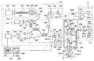
- FIG. 1is a schematic drawing of the first embodiment of a sentinel lymph node optical tomographic image obtaining apparatus according to the present invention
- FIG. 2is a schematic drawing of the second embodiment of a sentinel lymph node optical tomographic image obtaining apparatus according to the present invention
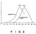
- FIG. 3is graph showing the spectra of light absorbed by indocyanine green, and the fluorescent spectra
- FIGS. 4A, 4 B, and 4 Care drawings provided for illustrating that which is displayed on the display screen.
- FIG. 1is a schematic drawing of the first embodiment of a sentinel lymph node optical tomographic image obtaining apparatus according to the present invention in its entirety.
- This sentinel lymph node optical tomographic image obtaining apparatuscarries out the detection of a sentinel lymph node by use of an RI method employing a radioisotope as a tracer, and obtains an ultrahigh-resolution optical tomographic image, which is a cellular level image, without the removal of the sentinel lymph node, and is applicable to open surgery.
- the sentinel lymph node optical tomographic image obtaining apparatuscomprises: a sentinel lymph node detecting portion 10 for detecting the sentinel lymph node by measuring the quantity of gamma radiation emitted from a radioisotope that has been injected in advance into the vicinity of a target subject including the sentinel lymph node; an OCT portion 11 for obtaining the optical tomographic data of the sentinel lymph node detected by said sentinel lymph node detecting portion 10 ; and a monitor 12 for displaying as a visible image the optical tomographic data obtained by the OCT means 11 .
- the sentinel lymph node detecting portion 10comprises a gamma-probe 80 for measuring the quantity of gamma radiation, and a gamma radiation quantity display portion 90 for displaying the measured value obtained by the gamma-probe 80 .
- the OCT portion 11comprises: a low-coherence light source 100 for emitting a low-coherence light L 1 having a core wavelength of 800 nm and a coherence length of 1.4 um; an aiming light source 110 for emitting an aiming light L 2 , which is visible light; a fiber optics coupling system 120 for combining the low-coherence light L 1 and the aiming light L 2 , and for separating and combining the reference-light L 3 and signal-light L 4 of the low-coherence light L 1 ; an optical path extending portion 130 disposed along the optical path of the reference-light L 3 , which causes the length of the optical path of said reference-light L 3 to change; a light scanning portion 140 for scanning a sentinel lymph node 1 with the signal-light L 4 ; a balance differential detecting portion 150 for detecting the signal strength of the interference light L 5 between the signal-light L 4 ′ reflected from a predetermined surface of the sentinel lymph node 1 and the reference-light L 3
- the light source portion 100 of the OCT portion 11is provided with an optical fiber light source 101 for emitting low-coherence light upon the entry therein of an excitation light; a semiconductor laser 102 for emitting a laser beam having a wavelength of 660 nm, which serves as the excitation light used to excite said optical fiber light source 101 ; a lens 103 for focusing the excitation light onto the input face of the optical fiber light source 101 ; an excitation light cutoff filter 104 for cutting off light having a wavelength of 700 nm or shorter, which includes the excitation light, from the low-coherence light; and a lens 105 and a lens 106 for focusing the low-coherence light emitted from the optical fiber light source 101 .
- the optical fiber light sourceis an optical fiber having a core 107 at the center thereof, and said core 107 has been doped with colorants that absorb excitation light and emit light.
- a low-coherence lighthaving a core wavelength of substantially 800 nm and a coherence length of 1.4 um is emitted from the output face thereof.
- the aiming-light source portion 110comprises a semiconductor laser 111 for emitting a red laser beam that serves as the aiming-light L 2 , and a lens 112 for focusing the aiming-light L 2 emitted from said semiconductor laser 111 .
- the fiber optics coupling system 120comprises: a fiber coupler 121 for separating the low-coherence light emitted from the optical fiber light source 101 into a signal-light L 4 and a reference-light L 3 , and for combining the signal-light L 4 ′ reflected from a predetermined depth of the sentinel lymph node 1 and the reference-light L 3 to obtain an interference light L 5 ; a fiber coupler 122 and a fiber coupler 123 provided between the light source portion 100 and the fiber coupler 121 ; a Piezo element 124 for slightly shifting the frequency of the reference-light L 3 ; a fiber 125 for connecting the light source portion 100 and the fiber coupler 122 ; a fiber 126 for connecting the aiming-light source portion 110 and the fiber coupler 123 ; a fiber 127 for connecting the balance differential detecting portion 150 and the optical path extending portion 130 , by way of the fiber couplers 121 and 122 ; and a fiber 128 for connecting the light-scanning portion 140 and
- the optical path extension portion 130comprises: a lens 131 for converting the reference-light L 3 emitted from the fiber 127 to a parallel light and for causing the reflected reference-light L 3 to enter the fiber 127 ; a prism 132 for changing the length of the optical path of the reference-light L 3 by moving said prism in the horizontal direction indicated in FIG. 1; and a drive unit 133 for moving said prism 132 in the horizontal direction.
- the light scanning unit 140comprises: a lens 141 for guiding the signal-light L 4 emitted from the fiber 128 to the sentinel lymph node 1 , and for causing the reflected signal-light L 4 ′ to enter the fiber 128 ; a mirror 142 ; a mirror 143 ; a lens 144 ; and a drive portion 145 for driving the mirrors 142 and 143 .
- the drive portion 145is connected to a manual input portion (not shown), and depending on a manual input to said manual input portion, a desired straight line portion is scanned by the light scanning portion 140 . Note that the light scanning portion 140 is a part of an attachment for use in open surgery (not shown).
- the balance differential detecting portion 150comprises a photodetector 151 and a photodetector 152 for measuring the signal strength of the interference light L 5 , and a differential amplifier 153 for adjusting the input balance of the detection values output by the photodetectors 151 and 152 and canceling out the noise component and drift component thereof, and then amplifying the difference therebetween.
- a radioisotopeis locally injected, endermically or by use of an endoscope, on the day prior to surgery into the vicinity of the target subject.
- the injected radioisotopeadvances towards the lymph nodes from the injection position, and stays for a set duration at the sentinel lymph node. A few hours after the radioisotope is injected a lymphosynthography is performed, and the approximate position is marked.
- the marked positionis cut open, and the quantity of gamma radiation emitted by the lymph nodes in the vicinity of the opened position is measured by the gamma-probe 80 as the position of the gamma-probe 80 is shifted in intervals of a microscopic distance.
- the operatorbased on the measured value displayed on the gamma radiation quantity display portion 90 , detects as the sentinel lymph node the lymph node emitting the most gamma radiation.
- the red aiming-light L 2 emitted from the semiconductor laser 111 of the aiming-light source portion 110is focused by the lens 112 and enters the fiber 126 .
- the aiming-light L 2passes through the fiber 126 , the fiber coupler 123 , the fiber 125 , the fiber coupler 122 , the fiber 127 , the fiber coupler 121 , and the fiber 128 , and is projected onto the sentinel lymph node 1 as a red spot beam by way of the lens 141 , the mirror 142 , the mirror 143 and the lens 144 .
- the angle at which the mirror 142 and the mirror 143 are disposedis controlled by the drive portion 145 , in response to a manual input inputted to a manual input portion (not shown)
- the operatorsets the measurement starting position and the measurement finishing position at the drive portion 145 , by use of the aiming-light, after the operator has controlled the angle of the mirrors 142 and 143 so that the aiming light L 2 is projected onto the sentinel lymph node 1 .
- the low-coherence light for obtaining an optical tomographic imageis emitted from the light source portion 100 .
- the mirrors 142 and 143are controlled by the drive portion 145 so as to be disposed at the angle at which the measurement initiation position is irradiated by said low-coherence light.
- the excitation light having a wavelength of 600 nm emitted from the semiconductor laser 102is focused by the lens 103 and enters the core 107 of the optical fiber light source 101 .
- said excitation lightis absorbed by the colorant with which the core 107 has been doped.
- the colorant absorbing the excitation lightmakes the transition from the base state to the excitation state; the colorant returns to the base state from the excitation state through the thermal relaxation and light emission processes.
- each individual light emittedis randomly amplified, with no interrelatedness therebetween; the light is conveyed through the core 107 , and emitted from the output face of the optical fiber light source 101 as spontaneously emitted light.
- This spontaneously emitted lightis a low-coherence light L 1 having the spectral characteristics determined by the spectra produced by the colorant with which the core 107 has been doped, and the conveyance characteristics of the optical fiber light source 101 . Further, the intensity of the low-coherence light L 1 is dependent upon the quantity of colorant with which the core 107 has been doped. That is to say, by selecting an appropriate type and quantity of colorant with which the core fiber is to be doped, as well as an appropriate length for the fiber optical light source 101 , a low-coherence light L 1 having a desired core wavelength, spectral width and intensity can be obtained.
- the optical fiber light source 101 employed in the current embodimentemits low coherence light L 1 having a core wavelength of substantially 800 nm and a coherence length of 1.4 um; said low coherence light L 1 is converted to a parallel light by the lens 105 , and after being transmitted by the excitation light cutoff filter 104 , is focused by the lens 106 and enters the fiber 125 .
- the low coherence light which passed through the fiber 125enters the fiber 127 at the fiber coupler 122 , and is separated at the fiber coupler 121 into a reference-light L 3 that proceeds within fiber 127 in the direction toward the optical path extending portion 130 , and a signal-light L 4 that proceeds within the fiber 128 in the direction toward the light scanning portion 140 .
- the reference-light L 3is modulated by the Piezo element 124 provided along the optical path, causing a slight difference ⁇ f between the frequency of the reference-light L 3 and the frequency of the signal-light L 4 to occur.
- the signal-light L 4is projected onto the sentinel lymph node 1 by way of the lens 141 , mirror 142 , mirror 143 , and lens 144 of the light scanning unit 140 .
- the signal-light L 4 ′which is the component of the signal-light L 4 entering the sentinel lymph node 1 that has been reflected at a predetermined depth thereof, is fed back via the lens 141 , the mirror 142 , the mirror 143 , and the lens 144 to the fiber 128 .
- the signal-light Ls′ that is fed back to the fiber 128is combined in the fiber 121 with the reference-light L 3 fed back to the fiber 127 , which is described below.
- the reference-light L 3 that has been modulated by the Piezo element 124passes through the fiber 127 and enters the prism 132 through the lens 131 of the optical path extending portion 130 , said modulated reference-light L 3 is then reflected by the prism 132 and is again transmitted by the lens 131 and fed back to the fiber 127 .
- the reference-light L 3 fed back to the fiber 127is combined in the fiber 121 with the signal-light L 4 ′ described above.
- the signal-light L 4 ′ and the reference-light L 3 combined in the fiber 121are again combined along the same axis, and at a predetermined timing, interference is caused between said signal-light L 4 ′ and reference-light L 3 , whereby said signal-light L 4 ′ and reference-light L 3 become an interference light L 5 and a beat signal is produced.
- the signal-light L 4 ′ and the reference-light L 3are low-coherence light of a short interference-susceptibility distance, after the low-coherence light has been separated into the signal-light L 4 and the reference-light L 3 , if the length of the optical path of the signal-light L 4 (L 4 ′) up to the point at which said signal-light L 4 (L 4 ′) arrives at the fiber 121 is substantially the same as the length of the optical path of the reference-light L 3 up to the point at which said reference-light L 3 arrives at the fiber 121 , both of said lights interfere with each other, said interference repeats in a strong-weak cycle according to the difference ⁇ f between the frequencies of the reference-light L 3 and the signal-light L 4 , and a beat signal is generated thereby.
- the interference light L 5is separated in the fiber coupler 121 : one of the separated components thereof enters the photodetector 151 of the balance differential detector 150 after passing through the fiber 127 ; and the other of the separated components thereof enters the photodetector 152 after passing through the fiber 128 .
- the photodetectors 151 and 152detect the signal strength of the beat signal from the interference light L 5 , and the differential amplifier 153 obtains the difference between the detection value of the photodetector 151 and the detection value of the photodetector 152 and outputs said difference to the signal processing portion 160 .
- the differential amplifier 153is provided with a function for adjusting the balance of the direct current component of the value input thereto, even in a case, for example, in which drift occurs in the low-coherence light emitted from the light source portion 100 , by amplifying the difference after adjusting the balance of the direct current component, the drift component is cancelled out, and only the beat signal component is detected.
- the prism 132is aligned, by the drive portion 133 , along the direction of the light axis. Therefore, the length of the optical path of the reference-light L 3 up to the point at which said reference-light L 3 arrives at the fiber 121 changes. Because the length of the optical path of the reference-light L 3 and the signal-light L 4 (L 4 ′) that interferes therewith is changed thereby, the depth at which the tomographic data of the sentinel lymph node 1 is obtained also changes.
- the entry point of the signal-light L 4is moved by the slight movement of the mirror 142 and the mirror 143 of the light scanning portion 140 in the direction of the finishing position of the measurement operation, which has been set in advance at the drive portion 145 , and the tomographic data is obtained to a predetermined depth in the same way.
- the optical tomographic data of the target subject 10can be obtained from the starting position of the measurement operation to the finishing position thereof.
- the signal processing portion 160performs a heterodyne detection to detect the strength of the signal-light L 4 ′ reflected by a predetermined surface of the sentinel lymph node 1 from the signal strength of the interference light L 5 detected by the balance differentiation detecting portion 150 , converts the obtained strength of the signal-light L 4 ′ to optical tomographic data, and outputs said optical tomographic data to the monitor 12 .
- the monitor 12displays as a visible-image the optical tomographic image data output from the image processing portion 160 . Note that by utilizing the low-coherence light having a coherence length of 1.4 ⁇ m emitted from the light source portion 100 , it becomes possible to obtain an ultra high resolution optical tomographic image, the resolution of which is improved to the cellular level.
- an ultra high resolution optical tomographic imageswhich is a cellular image, of the sentinel lymph node 1 can be obtained without surgically removing the sentinel lymph node 1 . Therefore, if a test for pathology is carried out, by a pathologist or a pathology diagnostic apparatus, employing this ultra high-resolution optical tomographic image of the sentinel lymph node, for cases in which it is determined that the disease has not metastasized to the sentinel lymph node, that is, for cases in which it is not necessary to surgically remove the sentinel lymph node, the surgery can be completed without surgically removing the sentinel lymph node. Further, because the wavelength of low-coherence light is 800 nm, the signal-light exhibits desirable transmittance and dispersion characteristics with respect to the sentinel lymph node 1 , and a desired optical tomographic image data can be obtained.
- FIG. 2is a schematic drawing of the second embodiment of a sentinel lymph node optical tomographic image obtaining apparatus according to the present invention in its entirety.
- This apparatusis implemented in the form of a laparoscope, and operates as follows: the cyanine colorant indocyanine green is injected into the body of the patient in the vicinity of the target subject; the target subject is then irradiated with an excitation light having a wavelength near the near-infrared wavelength band; a near-infrared fluorescent-light image formed of the near-infrared fluorescent light emitted from the target subject upon the irradiation thereof by the excitation light is obtained; said obtained near-infrared fluorescent-light image is converted to a visible-image and displayed; the sentinel lymph node which has emitted the fluorescent light is detected; and an optical tomographic image of the detected sentinel lymph node is obtained.
- the sentinel lymph node optical tomographic image obtaining apparatuscomprises: a laparoscope 20 to be inserted into the body of a patient; a target-subject image obtaining means 21 for obtaining a reflectance image and a near-infrared fluorescent-light image of the target subject; an OCT portion 22 for obtaining an optical tomographic image of the target subject; and a display portion 23 for displaying a target-subject image formed of the superimposed reflectance image and near-infrared fluorescent-light image, and the optical tomographic image of the sentinel lymph node.
- a laparoscope 20to be inserted into the body of a patient
- a target-subject image obtaining means 21for obtaining a reflectance image and a near-infrared fluorescent-light image of the target subject
- an OCT portion 22for obtaining an optical tomographic image of the target subject
- a display portion 23for displaying a target-subject image formed of the superimposed reflectance image and near-infrared
- the laparoscope 20is provided with an insertion portion 210 , and an image obtaining portion 220 .
- the insertion portion 210comprises: a light guide 211 extending internally to the distal end thereof; a switching mirror 212 for reflecting, when said mirror 212 is disposed in the position indicated by the solid line, the signal-light L 4 and the aiming light L 2 ; and a lens 213 for focusing a reflectance image formed of the reflected-light L 8 of the white-light L 6 , and a near-infrared fluorescent-light image formed of the near-infrared fluorescent light L 9 .
- an illuminating lens 214 and an objective lens 215are provided at the distal end of the light guide 211 and the switching mirror 212 , that is, at the distal end of the insertion portion 210 .
- the light guideis formed of a composite glass fiber, and is connected to the illuminating unit 200 , which is described below.
- the image obtaining portion 220is provided with: a near-infrared CCD 221 for obtaining a near-infrared fluorescent-light image; a color CCD 222 for obtaining a reflectance image; a dichroic mirror 223 for separating the near-infrared fluorescent light L 9 and the reflected-light L 8 ; an excitation light cutoff filter 224 for cutting the reflected excitation light L 7 from the reflected light L 8 , which has both said excitation light L 7 and the near-infrared fluorescent light L 9 as its components; a CCD cable 225 , which is connected to the near-infrared CCD 221 , for conveying an obtained image signal; and a CCD cable 226 , which is connected to the color CCD 222 , for conveying an obtained image signal.
- the dichroic mirror 223transmits light having a wavelength of 780 nm or shorter and reflects light having a wavelength longer than 780 nm, and the excitation light cutoff filter 224 cuts light having a wavelength of 800 nm or shorter.
- the target-subject image obtaining portion 21comprises an illumination unit 200 provided with a light source that emits white-light for obtaining a reflectance image and excitation light for obtaining a fluorescent-light image, and an image processing portion 230 .
- the illumination unit 200comprises: a semiconductor laser 201 that emits an excitation light L 7 having a wavelength of 790 nm; a white-light source 202 for emitting a white-light L 6 for obtaining a reflectance image; and a switching mirror 203 that switches between the irradiating of the white-light L 6 and the excitation light L 7 according to a predetermined timing.
- the image processing unit 230comprises: a reflectance image forming portion 231 for performing the image processing to display a reflectance image as a color image; a fluorescent-light image forming portion 232 for performing the image processing to display a near-infrared fluorescent-light image as a gradation image; and a superimposed-image forming portion 234 for superimposing the color image of a reflectance image and the gradation image of a near-infrared fluorescent-light image.
- the reflectance image forming portion 231performs image processing on a reflectance image obtained by the color CCD 222 to form a color image signal, and after being digitized, said color image signal is temporarily stored in a memory (not shown) The color image signal is read out from the memory in synchronization with the display timing, and after being D/A converted, said color image is again converted to a video signal and output to the superimposed-image forming portion 234 .
- the fluorescent-light image forming portion 232performs image processing on a reflectance image obtained by the near-infrared CCD 221 to form a gradation image signal, and after being digitized, said gradation image signal is temporarily stored in a memory (not shown).
- the gradation image signalis read out from the memory in synchronization with the display timing, and after being D/A converted, said gradation image is converted again to a video signal and output to the superimposed-image forming portion 234 .
- the superimposed-image forming portion 234superimposes the color image signal output from the reflectance image forming portion 231 and the gradation image signal output from the fluorescent-light image forming portion 232 , and outputs said superimposed color image signal and gradation image signal as a display image signal to the monitor 250 of the display portion 23 , which is described below.
- the OCT portion 22is provided with: a light source portion 100 for emitting a low-coherence light L 1 ; an aiming light source portion 110 for emitting an aiming light L 2 ; a fiber optics coupling system 120 for performing the separating and combining of each light; an optical path extending portion 130 for changing the length of the optical path of the reference-light L 3 ; a light scanning portion 240 for scanning the sentinel lymph node 1 of the target subject with the signal-light L 4 ; a balance differential detecting portion 150 for detecting the signal strength of the interference light L 5 ; and a signal processing portion 160 for performing a heterodyne detection and forming optical tomographic image data.
- the light scanning portion 240is provided with a lens 141 for guiding the signal-light L 4 emitted from the fiber 128 to the insertion portion 210 and also for causing the signal-light L 4 ′ reflected from the sentinel lymph node 1 to enter the fiber 128 ; a mirror 142 and a mirror 143 ; and a control portion 241 for controlling the angle at which the mirror 142 and the mirror 143 are disposed.
- the control portion 241is connected to the monitor 250 , which is described below, and controls the angle at which the mirror 142 and he mirror 143 are disposed so that the specified pixel position of the target-subject image displayed on the monitor 250 matches the scanning-position to be scanned by the signal-light L 4 .
- the display portion 23is provided with a monitor 12 for displaying an optical tomographic image, a monitor 250 for displaying a target-subject image; and a pen-type input portion for specifying a desired pixel position on the target-subject image displayed on the monitor 250 .
- each partis connected to a controller (not shown), and the operation timing thereof is controlled thereby.
- the operation of the sentinel lymph node optical tomographic image obtaining means of the configuration described abovewill be explained.
- the operation occurring when a target-subject image is obtained and the sentinel lymph node for a tumor occurring in the digestive tract of a patient is to be detectedwill be explained; then, the operation occurring when an optical tomographic image of the sentinel lymph node is to be obtained will be explained.
- an endoscopeis inserted into the digestive tract of the patient through the patient's mouth, and 5 mg of the cyanine type colorant indocyanine green per Kg of bodyweight of the patient is locally injected into the vicinity of a tumor.
- the indocyanine green binding to the proteins of blood vesselsshows the fluorescent spectra and the absorption spectra as shown in FIG. 3; the longest wavelength that the indocyanine green can absorb is 805 nm, and the longest wavelength of fluorescent light is 835 nm.
- the indocyanine green that has been locally injected into the vicinity of a tumorhas passed through the lymph system and is accumulated on the sentinel lymph node 11 .
- the sentinel lymph node 11is covered by a layer of tissue, such as fat, having a thickness of 1 cm or less. The detecting of the sentinel lymph node is carried out under these circumstances.
- the obtaining of a reflectance image and the obtaining of a near-infrared imageis performed in a time-division manner.
- the operation occurring when a reflectance image is to be obtainedwill be explained, and then the operation occurring when a fluorescent-light image is to be obtained will be explained.
- the switching mirror 212 with which the laparoscope insertion portion 210 is providedis disposed in the position indicated by the broken line so as not to interfere with the progress of the reflected-light L 8 and the near-infrared fluorescent-light L 9 .
- the switching mirror 203 within the illumination portion 200is moved to the position indicated by the broken line so as not to interfere with the progress of the white-light L 6 .
- the white-light L 6 emitted from the white-light source 202is enters the light guide 211 via the lens 205 and the lens 206 , and after being guided to the distal end of the insertion portion 210 of the laparoscope insertion portion 210 , said white-light L 6 is projected onto the target subject 2 , which includes the sentinel lymph node 1 , by the illuminating lens 214 .
- the reflected-light L 8 of the white-light L 6is focused by the objective lens 215 and focused onto the color CCD 222 by the lens 213 .
- the image signal obtained by photoelectrically converting the reflectance imageis output to the reflectance image forming portion 231 via the CCD cable 225 .
- the reflectance image forming portion 231first performs image processing such as amplification, blanking, clamping, 2-bit relative sampling, etc. on the image signal obtained by the color CCD 222 , and then separates the processed image signal obtained thereby into a brightness signal and a color signal, and computes a color image signal. After this, the color image signal is digitized and stored in a memory. The color image signal read out of the memory according to a display timing is converted into an analog signal, then converted further into a video signal. Said video signal is output to superimposing image forming portion 234 , and is output to the monitor 250 , after being superimposed with the gradation image signal of the fluorescent image described below, as a target area image signal.
- image processingsuch as amplification, blanking, clamping, 2-bit relative sampling, etc.
- the switching mirror 203is moved to the position indicated by the solid line so as not to reflect in the direction of the light guide 211 the excitation light L 7 emitted from the semiconductor laser 201 .
- the excitation light L 7 emitted from the semiconductor laser 201is directed toward the switching mirror 203 via the lens 204 .
- the excitation light L 7 reflected by the switching mirror 203enters the light guide 211 via the lens 206 , and after being guided to the distal end of the insertion portion 210 of the laparoscope insertion portion 210 , said white-light L 6 is projected onto the target subject 2 , which includes the sentinel lymph node 1 , by the illuminating lens 214 .
- the near-infrared fluorescent light L 9 emitted from the target subject 2 and the reflected-light of the excitation light L 7are focused by the focusing lens 215 and the lens 213 , reflected by the dichroic mirror 223 , and enter the excitation light cutoff filter 224 .
- the reflected-light of the excitation light L 7is cut by the excitation light cutoff filter 224 , and only the near-infrared fluorescent light L 9 enters the near-infrared CCD 221 .
- the light-sensitive portion of the near-infrared CCD 221photoelectrically converts the near-infrared fluorescent light L 9 , corresponding to the strength and weakness thereof, entering therein to obtain a signal charge, which is then output to the fluorescent-light image forming portion 232 .
- the fluorescent-light image forming portion 232performs image processing such as amplification, blanking, clamping, 2-bit relative sampling, etc. on the image signal output by the near-infrared CCD 221 , and forms, corresponding to the strength and weakness of the near-infrared fluorescent light, a gradation signal of the green color. After being digitized, said gradation signal is temporarily stored in a memory. The gradation signal is read out from the memory in synchronization with the display timing and D/A converted, and then converted to a video signal and output to the superimposed-image forming means 234 ; after being superimposed with the above-described color image signal, the superimposed signals are output to the monitor 250 as a target-subject image signal.
- image processingsuch as amplification, blanking, clamping, 2-bit relative sampling, etc.
- the reflectance imageis a color image such as that shown in FIG. 4A
- the fluorescent-light imageis a gradation image such as that shown in FIG. 4B
- the image formed by superimposing the color image signal and the gradation image signalis a target-subject image such as that shown in FIG. 4 C.
- the monitor 250converts the video signals input thereto to display image signals and displays said display image signals.
- the basic tone of the reflectance imagebecomes the red of the target subject, and because the higher the intensity of the light the denser the green of the gradation image becomes, the portion having the highest light intensity, that is, the place indicating the location of the sentinel lymph node 1 , is displayed as yellow. Note that the operation timing of the series of operations described above is controlled by the controller.
- the operatorviews the monitor 250 displaying the image of the target subject 2 , and can discern the position of the sentinel lymph node 1 therein. For cases in which the sentinel lymph node is covered in fatty tissue or the like, after such tissue is peeled away, the measurement starting position and measurement finishing position of the operation to obtain an optical tomographic image are set from the image displayed on the monitor 250 , by use of the pen-type input portion 253 .
- the control portion 241 of the light scanning portion 240computes the positions on the target subject to be scanned by the signal-light L 4 , based on the pixel positions of the measurement starting position and the measurement finishing position input into the monitor 250 , and controls the angle of the mirror 142 and the mirror 143 . Then, an optical tomographic image is obtained by the same operation as occurred in the first embodiment, and is displayed on the monitor 12 .
- the sentinel lymph node 1is detected by visually examining a fluorescent-light image obtained of the fluorescent light having a wavelength near the near-infrared wavelength band emitted from a target subject including the sentinel lymph node, into the vicinity of which a near-infrared fluorescent colorant has been injected in advance, upon the irradiation thereof by an excitation light, which has been converted to a visible-image and displayed, the sentinel lymph node can be detected easily and efficiently.
- the scanning-position to be scanned by the signal-light L 4can be automatically controlled so as to be the position of the sentinel lymph node 1 , the need to perform a cumbersome manual operation therefore is eliminated and an ultra high-resolution optical tomographic image of the sentinel lymph node 1 can be expediently obtained, whereby the overall benefit of employing the apparatus according to the current embodiment is improved.
- the measurement starting position and the measurement finishing positionhave been specified on the target-subject image by use of a pen-type input portion 251
- the current embodimentis not limited thereto: for example, the measurement starting position and the measurement finishing position have been specified on the target-subject image by clicking on the position indicated by a cursor pointing thereto; by inputting coordinates specifying the measurement starting position and the measurement finishing position; etc.
- the detecting of the sentinel lymph nodehas been performed by visually examining a target-subject image formed by superimposing a fluorescent-light image, which is a gradient image, and a color image of a reflectance image
- the current embodimentis not limited thereto: for example, the sentinel lymph node can be detected by examining an image displaying the intensity of the fluorescent light as a numerical value; the sentinel lymph node can be automatically detected by subjecting the area of a fluorescent-light image having the highest intensity of near-infrared fluorescent light to image processing; etc.
- a switching mirror 212has been employed at the distal end of the insertion portion 210 of the laparoscope portion 20 as an optical element for reflecting the aiming light L 2 and the signal-light L 4
- the current embodimentis not limited thereto; for example, a dichroic mirror or a half mirror can be used in place thereof. That is to say, any optical element that transmits at least one of the reflected-light L 8 and the near-infrared fluorescent-light L 9 and reflects at least one of the aiming light L 2 and signal-light 4 can be employed.
Landscapes
- Health & Medical Sciences (AREA)
- Life Sciences & Earth Sciences (AREA)
- Physics & Mathematics (AREA)
- General Health & Medical Sciences (AREA)
- General Physics & Mathematics (AREA)
- Veterinary Medicine (AREA)
- Public Health (AREA)
- Animal Behavior & Ethology (AREA)
- Engineering & Computer Science (AREA)
- Biomedical Technology (AREA)
- Molecular Biology (AREA)
- Medical Informatics (AREA)
- Heart & Thoracic Surgery (AREA)
- Surgery (AREA)
- Pathology (AREA)
- Biophysics (AREA)
- Nuclear Medicine, Radiotherapy & Molecular Imaging (AREA)
- Radiology & Medical Imaging (AREA)
- Immunology (AREA)
- Vascular Medicine (AREA)
- Epidemiology (AREA)
- Investigating Or Analysing Materials By Optical Means (AREA)
- Length Measuring Devices By Optical Means (AREA)
- Investigating, Analyzing Materials By Fluorescence Or Luminescence (AREA)
Abstract
Description
Claims (12)
Applications Claiming Priority (3)
| Application Number | Priority Date | Filing Date | Title |
|---|---|---|---|
| JP292105/2000 | 2000-09-26 | ||
| JP2000292105AJP2002095663A (en) | 2000-09-26 | 2000-09-26 | Method of acquiring optical tomographic image of sentinel lymph node and its device |
| JP2000/292105 | 2000-09-26 |
Publications (2)
| Publication Number | Publication Date |
|---|---|
| US20020037252A1 US20020037252A1 (en) | 2002-03-28 |
| US6636755B2true US6636755B2 (en) | 2003-10-21 |
Family
ID=18775092
Family Applications (1)
| Application Number | Title | Priority Date | Filing Date |
|---|---|---|---|
| US09/962,195Expired - Fee RelatedUS6636755B2 (en) | 2000-09-26 | 2001-09-26 | Method and apparatus for obtaining an optical tomographic image of a sentinel lymph node |
Country Status (2)
| Country | Link |
|---|---|
| US (1) | US6636755B2 (en) |
| JP (1) | JP2002095663A (en) |
Cited By (33)
| Publication number | Priority date | Publication date | Assignee | Title |
|---|---|---|---|---|
| US20020013531A1 (en)* | 2000-04-25 | 2002-01-31 | Katsumi Hayashi | Sentinel lymph node detection method and system therefor |
| US20040021771A1 (en)* | 2002-07-16 | 2004-02-05 | Xenogen Corporation | Method and apparatus for 3-D imaging of internal light sources |
| US20050020923A1 (en)* | 2003-03-04 | 2005-01-27 | Frangioni John V. | Materials and methods for near-infrared and infrared lymph node mapping |
| US20060132790A1 (en)* | 2003-02-20 | 2006-06-22 | Applied Science Innovations, Inc. | Optical coherence tomography with 3d coherence scanning |
| US20060257007A1 (en)* | 2005-04-14 | 2006-11-16 | Ernst Bartsch | Method and device for analysis of three-dimensional digital image data |
| US20060268153A1 (en)* | 2005-05-11 | 2006-11-30 | Xenogen Corporation | Surface contruction using combined photographic and structured light information |
| US20070077045A1 (en)* | 2005-09-30 | 2007-04-05 | Fuji Photo Film Co., Ltd. | Optical tomography system |
| US20070076213A1 (en)* | 2005-09-30 | 2007-04-05 | Fuji Photo Film Co., Ltd. | Optical tomography system |
| US20070167842A1 (en)* | 2005-12-22 | 2007-07-19 | Olympus Corporation | In-vivo examination method and in-vivo examination apparatus |
| US20070253908A1 (en)* | 2002-07-16 | 2007-11-01 | Xenogen Corporation | Fluorescent light tomography |
| US7298415B2 (en) | 2001-07-13 | 2007-11-20 | Xenogen Corporation | Structured light imaging apparatus |
| US20070270697A1 (en)* | 2001-05-17 | 2007-11-22 | Xenogen Corporation | Method and apparatus for determining target depth, brightness and size within a body region |
| US20080056999A1 (en)* | 2006-08-24 | 2008-03-06 | Baylor College Of Medicine | Imaging agents for functional imaging of lymphatic structures |
| US20080255460A1 (en)* | 2007-04-13 | 2008-10-16 | Ethicon Endo-Surgery, Inc. | Nanoparticle tissue based identification and illumination |
| EP2060227A1 (en)* | 2007-11-15 | 2009-05-20 | Carestream Health, Inc. | Multimodal imaging system for tissue imaging |
| US20090185191A1 (en)* | 2008-01-18 | 2009-07-23 | Boppart Stephen A | Device and method for imaging the ear using optical coherence tomography |
| US7566476B2 (en) | 1997-11-13 | 2009-07-28 | Massachusetts Institute Of Technology | Highly luminescent color-selective nanocrystalline materials |
| US20090192349A1 (en)* | 2008-01-24 | 2009-07-30 | Lifeguard Surgical Systems | Common bile duct surgical imaging system |
| US20090221920A1 (en)* | 2008-01-18 | 2009-09-03 | Boppart Stephen A | Low-coherence interferometry and optical coherence tomography for image-guided surgical treatment of solid tumors |
| US20100076279A1 (en)* | 2008-09-23 | 2010-03-25 | Shuros Allan C | Method and apparatus for organ specific inflammation monitoring |
| US8071359B2 (en) | 1997-11-25 | 2011-12-06 | The Regents Of The University Of California | Semiconductor nanocrystal probes for biological applications and process for making and using such probes |
| CN102282456A (en)* | 2009-01-30 | 2011-12-14 | 兴和株式会社 | optical camera |
| US20120232381A1 (en)* | 2009-09-25 | 2012-09-13 | Stichting Het Nederlands Kanker Instituut | Method for non-invasive quantitative assessment of radioactive tracer levels in the blood stream |
| US8317776B2 (en) | 2007-12-18 | 2012-11-27 | The Invention Science Fund I, Llc | Circulatory monitoring systems and methods |
| US8409132B2 (en) | 2007-12-18 | 2013-04-02 | The Invention Science Fund I, Llc | Treatment indications informed by a priori implant information |
| US8636670B2 (en) | 2008-05-13 | 2014-01-28 | The Invention Science Fund I, Llc | Circulatory monitoring systems and methods |
| US8655431B2 (en) | 2011-05-31 | 2014-02-18 | Vanderbilt University | Apparatus and method for real-time imaging and monitoring of an electrosurgical procedure |
| US20140267603A1 (en)* | 2013-03-15 | 2014-09-18 | Intuitive Surgical Operations, Inc. | Depth based modification of captured images |
| US9677869B2 (en) | 2012-12-05 | 2017-06-13 | Perimeter Medical Imaging, Inc. | System and method for generating a wide-field OCT image of a portion of a sample |
| US9757038B2 (en) | 2011-05-31 | 2017-09-12 | Vanderbilt University | Optical coherence tomography probe |
| US10577573B2 (en) | 2017-07-18 | 2020-03-03 | Perimeter Medical Imaging, Inc. | Sample container for stabilizing and aligning excised biological tissue samples for ex vivo analysis |
| US10775308B2 (en) | 2006-08-24 | 2020-09-15 | Xenogen Corporation | Apparatus and methods for determining optical tissue properties |
| US11730370B2 (en) | 2006-08-24 | 2023-08-22 | Xenogen Corporation | Spectral unmixing for in-vivo imaging |
Families Citing this family (70)
| Publication number | Priority date | Publication date | Assignee | Title |
|---|---|---|---|---|
| US7231243B2 (en) | 2000-10-30 | 2007-06-12 | The General Hospital Corporation | Optical methods for tissue analysis |
| US7139598B2 (en)* | 2002-04-04 | 2006-11-21 | Veralight, Inc. | Determination of a measure of a glycation end-product or disease state using tissue fluorescence |
| WO2002088684A1 (en) | 2001-04-30 | 2002-11-07 | The General Hospital Corporation | Method and apparatus for improving image clarity and sensitivity in optical coherence tomography using dynamic feedback to control focal properties and coherence gating |
| EP2098977B1 (en) | 2002-05-09 | 2012-11-21 | Sony Corporation | Method of detecting biological pattern, biological pattern detector, method of biological certificate and biological certificate apparatus |
| AU2003297099A1 (en)* | 2002-12-12 | 2004-06-30 | Manoa Medical, Inc. | Percutaneous removal of sentinel lymph node using contrast imaging for identification |
| EP2436307B1 (en) | 2003-03-31 | 2015-10-21 | The General Hospital Corporation | Speckle reduction in optical coherence tomography by path length encoded angular compounding |
| KR101386971B1 (en) | 2003-06-06 | 2014-04-18 | 더 제너럴 하스피탈 코포레이션 | Process and apparatus for a wavelength tunning source |
| EP1688083B1 (en) | 2003-11-20 | 2018-09-12 | Hamamatsu Photonics K.K. | Lymph node detector |
| EP1727460A2 (en)* | 2004-03-11 | 2006-12-06 | The General Hospital Corporation | Method and system for tomographic imaging using fluorescent proteins |
| JP2006014868A (en) | 2004-06-30 | 2006-01-19 | Hamamatsu Photonics Kk | Lymph node detecting apparatus |
| AU2005270037B2 (en) | 2004-07-02 | 2012-02-09 | The General Hospital Corporation | Endoscopic imaging probe comprising dual clad fibre |
| EP2272421A1 (en) | 2004-08-24 | 2011-01-12 | The General Hospital Corporation | Method and apparatus for imaging of vessel segments |
| WO2006024014A2 (en) | 2004-08-24 | 2006-03-02 | The General Hospital Corporation | Process, system and software arrangement for measuring a mechanical strain and elastic properties of a sample |
| JP4654357B2 (en)* | 2004-08-26 | 2011-03-16 | 日本電信電話株式会社 | Optical interference tomography light generator for biological tissue measurement and optical interference tomography device for biological tissue measurement |
| EP1655040A1 (en)* | 2004-10-08 | 2006-05-10 | Bracco Imaging, S.P.A. | Contrast agent formulations for the visualization of the lymphatic system |
| WO2006058346A1 (en) | 2004-11-29 | 2006-06-01 | The General Hospital Corporation | Arrangements, devices, endoscopes, catheters and methods for performing optical imaging by simultaneously illuminating and detecting multiple points on a sample |
| ES2337497T3 (en)* | 2005-04-28 | 2010-04-26 | The General Hospital Corporation | EVALUATION OF CHARACTERISTICS OF THE IMAGE OF AN ANATOMICAL STRUCTURE IN IMAGES OF TOMOGRAPHY OF OPTICAL COHERENCE. |
| US9060689B2 (en) | 2005-06-01 | 2015-06-23 | The General Hospital Corporation | Apparatus, method and system for performing phase-resolved optical frequency domain imaging |
| EP2267404B1 (en) | 2005-08-09 | 2016-10-05 | The General Hospital Corporation | Apparatus and method for performing polarization-based quadrature demodulation in optical coherence tomography |
| US7843572B2 (en) | 2005-09-29 | 2010-11-30 | The General Hospital Corporation | Method and apparatus for optical imaging via spectral encoding |
| DK1973466T3 (en) | 2006-01-19 | 2021-02-01 | Massachusetts Gen Hospital | BALLOON IMAGING CATHETER |
| US8145018B2 (en) | 2006-01-19 | 2012-03-27 | The General Hospital Corporation | Apparatus for obtaining information for a structure using spectrally-encoded endoscopy techniques and methods for producing one or more optical arrangements |
| WO2007149602A2 (en) | 2006-02-01 | 2007-12-27 | The General Hospital Corporation | Methods and systems for providing electromagnetic radiation to at least one portion of a sample using conformal laser therapy procedures |
| JP5680829B2 (en) | 2006-02-01 | 2015-03-04 | ザ ジェネラル ホスピタル コーポレイション | A device that irradiates a sample with multiple electromagnetic radiations |
| EP2982929A1 (en) | 2006-02-24 | 2016-02-10 | The General Hospital Corporation | Methods and systems for performing angle-resolved fourier-domain optical coherence tomography |
| WO2007133961A2 (en) | 2006-05-10 | 2007-11-22 | The General Hospital Corporation | Processes, arrangements and systems for providing frequency domain imaging of a sample |
| US8838213B2 (en) | 2006-10-19 | 2014-09-16 | The General Hospital Corporation | Apparatus and method for obtaining and providing imaging information associated with at least one portion of a sample, and effecting such portion(s) |
| US9176319B2 (en) | 2007-03-23 | 2015-11-03 | The General Hospital Corporation | Methods, arrangements and apparatus for utilizing a wavelength-swept laser using angular scanning and dispersion procedures |
| US10534129B2 (en) | 2007-03-30 | 2020-01-14 | The General Hospital Corporation | System and method providing intracoronary laser speckle imaging for the detection of vulnerable plaque |
| EP2197511B1 (en)* | 2008-01-25 | 2021-01-06 | Fresenius Medical Care Holdings, Inc. | Apparatus for early stage peritonitis detection |
| EP2191770B1 (en) | 2008-05-02 | 2016-04-13 | Olympus Corporation | Optical inspection device, electromagnetic wave detection method, electromagnetic wave detection device, organism observation method, microscope, endoscope, and optical tomographic image generation device |
| US8956591B2 (en) | 2008-05-15 | 2015-02-17 | Osaka Prefectural Hospital Organization | Method for detecting cancer using ICG fluorescence method |
| WO2010009136A2 (en) | 2008-07-14 | 2010-01-21 | The General Hospital Corporation | Apparatus and methods for color endoscopy |
| JP5731394B2 (en) | 2008-12-10 | 2015-06-10 | ザ ジェネラル ホスピタル コーポレイション | System, apparatus and method for extending imaging depth range of optical coherence tomography through optical subsampling |
| JP2012515576A (en) | 2009-01-20 | 2012-07-12 | ザ ジェネラル ホスピタル コーポレイション | Endoscopic biopsy device, system, and method |
| CA2749670A1 (en) | 2009-02-04 | 2010-08-12 | The General Hospital Corporation | Apparatus and method for utilization of a high-speed optical wavelength tuning source |
| JP5819823B2 (en) | 2009-07-14 | 2015-11-24 | ザ ジェネラル ホスピタル コーポレイション | Device for measuring the flow and pressure inside a blood vessel and method of operating the device |
| KR20130004326A (en) | 2010-03-05 | 2013-01-09 | 더 제너럴 하스피탈 코포레이션 | Systems, methods and computer-accessible medium which provide microscopic images of at least one anatomical structure at a particular resolution |
| US9069130B2 (en) | 2010-05-03 | 2015-06-30 | The General Hospital Corporation | Apparatus, method and system for generating optical radiation from biological gain media |
| EP2575597B1 (en) | 2010-05-25 | 2022-05-04 | The General Hospital Corporation | Apparatus for providing optical imaging of structures and compositions |
| EP2575598A2 (en) | 2010-05-25 | 2013-04-10 | The General Hospital Corporation | Apparatus, systems, methods and computer-accessible medium for spectral analysis of optical coherence tomography images |
| JP6066901B2 (en) | 2010-06-03 | 2017-01-25 | ザ ジェネラル ホスピタル コーポレイション | Method for apparatus and device for imaging structures in or in one or more luminal organs |
| US10682198B2 (en) | 2010-07-02 | 2020-06-16 | Intuitive Surgical Operations, Inc. | Method and system for fluorescent imaging with background surgical image composed of selective illumination spectra |
| US9211058B2 (en)* | 2010-07-02 | 2015-12-15 | Intuitive Surgical Operations, Inc. | Method and system for fluorescent imaging with background surgical image composed of selective illumination spectra |
| WO2012058381A2 (en) | 2010-10-27 | 2012-05-03 | The General Hospital Corporation | Apparatus, systems and methods for measuring blood pressure within at least one vessel |
| US9330092B2 (en) | 2011-07-19 | 2016-05-03 | The General Hospital Corporation | Systems, methods, apparatus and computer-accessible-medium for providing polarization-mode dispersion compensation in optical coherence tomography |
| JP2015502562A (en) | 2011-10-18 | 2015-01-22 | ザ ジェネラル ホスピタル コーポレイション | Apparatus and method for generating and / or providing recirculating optical delay |
| WO2013148306A1 (en) | 2012-03-30 | 2013-10-03 | The General Hospital Corporation | Imaging system, method and distal attachment for multidirectional field of view endoscopy |
| US9511152B2 (en)* | 2012-04-05 | 2016-12-06 | The Board Of Regents Of The University Of Texas System | Multicolored pH-activatable fluorescence nanoplatform |
| JP2015517387A (en) | 2012-05-21 | 2015-06-22 | ザ ジェネラル ホスピタル コーポレイション | Apparatus, device and method for capsule microscopy |
| JP6227652B2 (en) | 2012-08-22 | 2017-11-08 | ザ ジェネラル ホスピタル コーポレイション | System, method, and computer-accessible medium for fabricating a miniature endoscope using soft lithography |
| US9968261B2 (en) | 2013-01-28 | 2018-05-15 | The General Hospital Corporation | Apparatus and method for providing diffuse spectroscopy co-registered with optical frequency domain imaging |
| WO2014120791A1 (en) | 2013-01-29 | 2014-08-07 | The General Hospital Corporation | Apparatus, systems and methods for providing information regarding the aortic valve |
| US11179028B2 (en) | 2013-02-01 | 2021-11-23 | The General Hospital Corporation | Objective lens arrangement for confocal endomicroscopy |
| CN103163111B (en)* | 2013-02-25 | 2015-11-04 | 天津大学 | A combined fluorescence mesoscopic imaging and OCT early cervical cancer detection system |
| US10478072B2 (en) | 2013-03-15 | 2019-11-19 | The General Hospital Corporation | Methods and system for characterizing an object |
| EP2997354A4 (en) | 2013-05-13 | 2017-01-18 | The General Hospital Corporation | Detecting self-interefering fluorescence phase and amplitude |
| WO2015009932A1 (en) | 2013-07-19 | 2015-01-22 | The General Hospital Corporation | Imaging apparatus and method which utilizes multidirectional field of view endoscopy |
| EP3021735A4 (en) | 2013-07-19 | 2017-04-19 | The General Hospital Corporation | Determining eye motion by imaging retina. with feedback |
| WO2015013651A2 (en) | 2013-07-26 | 2015-01-29 | The General Hospital Corporation | System, apparatus and method utilizing optical dispersion for fourier-domain optical coherence tomography |
| WO2015105870A1 (en) | 2014-01-08 | 2015-07-16 | The General Hospital Corporation | Method and apparatus for microscopic imaging |
| US10736494B2 (en) | 2014-01-31 | 2020-08-11 | The General Hospital Corporation | System and method for facilitating manual and/or automatic volumetric imaging with real-time tension or force feedback using a tethered imaging device |
| WO2015153982A1 (en) | 2014-04-04 | 2015-10-08 | The General Hospital Corporation | Apparatus and method for controlling propagation and/or transmission of electromagnetic radiation in flexible waveguide(s) |
| US10912462B2 (en) | 2014-07-25 | 2021-02-09 | The General Hospital Corporation | Apparatus, devices and methods for in vivo imaging and diagnosis |
| US11583222B2 (en)* | 2017-05-19 | 2023-02-21 | Covidien Lp | Systems, devices, and methods for lymph specimen tracking, drainage determination, visualization, and treatment |
| JP6908131B2 (en)* | 2017-12-25 | 2021-07-21 | 日本電気株式会社 | Optical beam controller and optical interference tomographic imager using it |
| JP2020171429A (en)* | 2019-04-09 | 2020-10-22 | 株式会社島津製作所 | Imaging device and imaging method |
| CN112033301B (en)* | 2020-08-07 | 2021-05-07 | 太原理工大学 | A fiber optic measurement system for the bending degree of a scraper |
| KR102826240B1 (en)* | 2022-06-24 | 2025-06-27 | 주식회사 메타플바이오 | Multispectral fluorescence imaging apparatus |
| KR20250122010A (en)* | 2024-02-05 | 2025-08-13 | 재단법인 아산사회복지재단 | Lymphatic contraction signal real-time detection device and method |
Citations (5)
| Publication number | Priority date | Publication date | Assignee | Title |
|---|---|---|---|---|
| US6002480A (en)* | 1997-06-02 | 1999-12-14 | Izatt; Joseph A. | Depth-resolved spectroscopic optical coherence tomography |
| JP2000124600A (en) | 1998-10-15 | 2000-04-28 | Sony Corp | Soldering evaluation test board and solder evaluation method |
| US6134003A (en)* | 1991-04-29 | 2000-10-17 | Massachusetts Institute Of Technology | Method and apparatus for performing optical measurements using a fiber optic imaging guidewire, catheter or endoscope |
| US6167297A (en)* | 1999-05-05 | 2000-12-26 | Benaron; David A. | Detecting, localizing, and targeting internal sites in vivo using optical contrast agents |
| US6350431B1 (en)* | 1997-04-29 | 2002-02-26 | Nycomed Imaging As | Compounds |
Family Cites Families (2)
| Publication number | Priority date | Publication date | Assignee | Title |
|---|---|---|---|---|
| JP2001515382A (en)* | 1997-03-06 | 2001-09-18 | マサチューセッツ インスティチュート オブ テクノロジー | Equipment for optical scanning of living tissue |
| JP2001299676A (en)* | 2000-04-25 | 2001-10-30 | Fuji Photo Film Co Ltd | Method and system for detecting sentinel lymph node |
- 2000
- 2000-09-26JPJP2000292105Apatent/JP2002095663A/enactivePending
- 2001
- 2001-09-26USUS09/962,195patent/US6636755B2/ennot_activeExpired - Fee Related
Patent Citations (5)
| Publication number | Priority date | Publication date | Assignee | Title |
|---|---|---|---|---|
| US6134003A (en)* | 1991-04-29 | 2000-10-17 | Massachusetts Institute Of Technology | Method and apparatus for performing optical measurements using a fiber optic imaging guidewire, catheter or endoscope |
| US6350431B1 (en)* | 1997-04-29 | 2002-02-26 | Nycomed Imaging As | Compounds |
| US6002480A (en)* | 1997-06-02 | 1999-12-14 | Izatt; Joseph A. | Depth-resolved spectroscopic optical coherence tomography |
| JP2000124600A (en) | 1998-10-15 | 2000-04-28 | Sony Corp | Soldering evaluation test board and solder evaluation method |
| US6167297A (en)* | 1999-05-05 | 2000-12-26 | Benaron; David A. | Detecting, localizing, and targeting internal sites in vivo using optical contrast agents |
Non-Patent Citations (2)
| Title |
|---|
| Abstract JP2000-124600, Apr. 28, 2000. |
| Houston, J. P. et al., "Sensitivity and depth penetration of continuous wave versus frequency-domain photon migration near-infrared fluorescence contrast enhanced imaging" Apr. 2003, Photochemistry and Photobiology; Augusta.** |
Cited By (94)
| Publication number | Priority date | Publication date | Assignee | Title |
|---|---|---|---|---|
| US8481113B2 (en) | 1997-11-13 | 2013-07-09 | Massachusetts Institute Of Technology | Highly luminescent color-selective nanocrystalline materials |
| US9790424B2 (en) | 1997-11-13 | 2017-10-17 | Massachusetts Institute Of Technology | Highly luminescent color-selective nanocrystalline materials |
| US9441156B2 (en) | 1997-11-13 | 2016-09-13 | Massachusetts Institute Of Technology | Highly luminescent color-selective nanocrystalline materials |
| US8158193B2 (en) | 1997-11-13 | 2012-04-17 | Massachusetts Institute Of Technology | Highly luminescent color-selective nanocrystalline materials |
| US7566476B2 (en) | 1997-11-13 | 2009-07-28 | Massachusetts Institute Of Technology | Highly luminescent color-selective nanocrystalline materials |
| US8101234B2 (en) | 1997-11-13 | 2012-01-24 | Massachusetts Institute Of Technology | Highly luminescent color-selective nanocrystalline materials |
| US8481112B2 (en) | 1997-11-13 | 2013-07-09 | Massachusetts Institute Of Technology | Highly luminescent color-selective nanocrystalline materials |
| US8288152B2 (en) | 1997-11-25 | 2012-10-16 | The Regents Of The University Of California | Semiconductor nanocrystal probes for biological applications and process for making and using such probes |
| US8639449B2 (en) | 1997-11-25 | 2014-01-28 | The Regents Of The University Of California | Semiconductor nanocrystal probes for biological applications and process for making and using such probes |
| US8071359B2 (en) | 1997-11-25 | 2011-12-06 | The Regents Of The University Of California | Semiconductor nanocrystal probes for biological applications and process for making and using such probes |
| US8071361B2 (en) | 1997-11-25 | 2011-12-06 | The Regents Of The University Of California | Semiconductor nanocrystal probes for biological applications and process for making and using such probes |
| US8071360B2 (en) | 1997-11-25 | 2011-12-06 | The Regents Of The University Of California | Semiconductor nanocrystal probes for biological applications and process for making and using such probes |
| US8288153B2 (en) | 1997-11-25 | 2012-10-16 | The Regents Of The University Of California | Semiconductor nanocrystal probes for biological applications and process for making and using such probes |
| US9530928B2 (en) | 1997-11-25 | 2016-12-27 | The Regents Of The University Of California | Semiconductor nanocrystal probes for biological applications and process for making and using such probes |
| US20020013531A1 (en)* | 2000-04-25 | 2002-01-31 | Katsumi Hayashi | Sentinel lymph node detection method and system therefor |
| US6804549B2 (en)* | 2000-04-25 | 2004-10-12 | Fuji Photo Film Co., Ltd. | Sentinel lymph node detection method and system therefor |
| US7764986B2 (en) | 2001-05-17 | 2010-07-27 | Xenogen Corporation | Method and apparatus for determining target depth, brightness and size within a body region |
| US8825140B2 (en) | 2001-05-17 | 2014-09-02 | Xenogen Corporation | Imaging system |
| US20070270697A1 (en)* | 2001-05-17 | 2007-11-22 | Xenogen Corporation | Method and apparatus for determining target depth, brightness and size within a body region |
| US7403812B2 (en) | 2001-05-17 | 2008-07-22 | Xenogen Corporation | Method and apparatus for determining target depth, brightness and size within a body region |
| US20100262019A1 (en)* | 2001-05-17 | 2010-10-14 | Xenogen Corporation | Method and apparatus for determining target depth, brightness and size within a body region |
| US8180435B2 (en) | 2001-05-17 | 2012-05-15 | Xenogen Corporation | Method and apparatus for determining target depth, brightness and size within a body region |
| US20080079802A1 (en)* | 2001-07-13 | 2008-04-03 | Xenogen Corporation | Structured light imaging apparatus |
| US8279334B2 (en) | 2001-07-13 | 2012-10-02 | Xenogen Corporation | Structured light imaging apparatus |
| US7298415B2 (en) | 2001-07-13 | 2007-11-20 | Xenogen Corporation | Structured light imaging apparatus |
| US7555332B2 (en) | 2002-07-16 | 2009-06-30 | Xenogen Corporation | Fluorescent light tomography |
| US20070253908A1 (en)* | 2002-07-16 | 2007-11-01 | Xenogen Corporation | Fluorescent light tomography |
| US20040021771A1 (en)* | 2002-07-16 | 2004-02-05 | Xenogen Corporation | Method and apparatus for 3-D imaging of internal light sources |
| US20050201614A1 (en)* | 2002-07-16 | 2005-09-15 | Xenogen Corporation | 3-D in-vivo imaging and topography using structured light |
| US8909326B2 (en) | 2002-07-16 | 2014-12-09 | Xenogen Corporation | Method and apparatus for 3-D imaging of internal light sources |
| US20110090316A1 (en)* | 2002-07-16 | 2011-04-21 | Xenogen Corporation | Method and apparatus for 3-d imaging of internal light sources |
| US7860549B2 (en) | 2002-07-16 | 2010-12-28 | Xenogen Corporation | Method and apparatus for 3-D imaging of internal light sources |
| US7797034B2 (en) | 2002-07-16 | 2010-09-14 | Xenogen Corporation | 3-D in-vivo imaging and topography using structured light |
| US20080031494A1 (en)* | 2002-07-16 | 2008-02-07 | Xenogen Corporation | Fluorescent light tomography |
| US20080018899A1 (en)* | 2002-07-16 | 2008-01-24 | Xenogen Corporation | Method and apparatus for 3-d imaging of internal light sources |
| US7599731B2 (en) | 2002-07-16 | 2009-10-06 | Xenogen Corporation | Fluorescent light tomography |
| US7603167B2 (en) | 2002-07-16 | 2009-10-13 | Xenogen Corporation | Method and apparatus for 3-D imaging of internal light sources |
| US7616985B2 (en) | 2002-07-16 | 2009-11-10 | Xenogen Corporation | Method and apparatus for 3-D imaging of internal light sources |
| US20100022872A1 (en)* | 2002-07-16 | 2010-01-28 | Xenogen Corporation | Method and apparatus for 3-d imaging of internal light sources |
| US7474407B2 (en) | 2003-02-20 | 2009-01-06 | Applied Science Innovations | Optical coherence tomography with 3d coherence scanning |
| US20060132790A1 (en)* | 2003-02-20 | 2006-06-22 | Applied Science Innovations, Inc. | Optical coherence tomography with 3d coherence scanning |
| US7181266B2 (en)* | 2003-03-04 | 2007-02-20 | Massachusetts Institute Of Technology | Materials and methods for near-infrared and infrared lymph node mapping |
| US20050020923A1 (en)* | 2003-03-04 | 2005-01-27 | Frangioni John V. | Materials and methods for near-infrared and infrared lymph node mapping |
| US20060257007A1 (en)* | 2005-04-14 | 2006-11-16 | Ernst Bartsch | Method and device for analysis of three-dimensional digital image data |
| US20060268153A1 (en)* | 2005-05-11 | 2006-11-30 | Xenogen Corporation | Surface contruction using combined photographic and structured light information |
| US8044996B2 (en) | 2005-05-11 | 2011-10-25 | Xenogen Corporation | Surface construction using combined photographic and structured light information |
| US20070076213A1 (en)* | 2005-09-30 | 2007-04-05 | Fuji Photo Film Co., Ltd. | Optical tomography system |
| US20070077045A1 (en)* | 2005-09-30 | 2007-04-05 | Fuji Photo Film Co., Ltd. | Optical tomography system |
| US7593626B2 (en)* | 2005-09-30 | 2009-09-22 | Fujifilm Corporation | Optical tomography system |
| US7583385B2 (en)* | 2005-09-30 | 2009-09-01 | Fujifilm Corporation | Optical tomography system |
| US20070167842A1 (en)* | 2005-12-22 | 2007-07-19 | Olympus Corporation | In-vivo examination method and in-vivo examination apparatus |
| US7801589B2 (en)* | 2005-12-22 | 2010-09-21 | Olympus Corporation | In-vivo examination method and in-vivo examination apparatus |
| US7875260B2 (en) | 2006-08-24 | 2011-01-25 | Baylor College Of Medicine | Imaging agents for functional imaging of lymphatic structures |
| US20080064954A1 (en)* | 2006-08-24 | 2008-03-13 | Baylor College Of Medicine | Method of measuring propulsion in lymphatic structures |
| US20080056999A1 (en)* | 2006-08-24 | 2008-03-06 | Baylor College Of Medicine | Imaging agents for functional imaging of lymphatic structures |
| US11730370B2 (en) | 2006-08-24 | 2023-08-22 | Xenogen Corporation | Spectral unmixing for in-vivo imaging |
| US10775308B2 (en) | 2006-08-24 | 2020-09-15 | Xenogen Corporation | Apparatus and methods for determining optical tissue properties |
| US20080255403A1 (en)* | 2007-04-13 | 2008-10-16 | Ethicon Endo-Surgery, Inc. | Magnetic nanoparticle therapies |
| US8062215B2 (en) | 2007-04-13 | 2011-11-22 | Ethicon Endo-Surgery, Inc. | Fluorescent nanoparticle scope |
| US20080255459A1 (en)* | 2007-04-13 | 2008-10-16 | Ethicon Endo-Surgery, Inc. | Sentinel node identification using fluorescent nanoparticles |
| US8239007B2 (en) | 2007-04-13 | 2012-08-07 | Ethicon Endo-Surgert, Inc. | Biocompatible nanoparticle compositions and methods |
| US8239008B2 (en)* | 2007-04-13 | 2012-08-07 | Ethicon Endo-Surgery, Inc. | Sentinel node identification using fluorescent nanoparticles |
| US20080255425A1 (en)* | 2007-04-13 | 2008-10-16 | Ethicon Endo-Surgery, Inc. | Nanoparticle treated medical devices |
| US20080255460A1 (en)* | 2007-04-13 | 2008-10-16 | Ethicon Endo-Surgery, Inc. | Nanoparticle tissue based identification and illumination |
| EP2060227A1 (en)* | 2007-11-15 | 2009-05-20 | Carestream Health, Inc. | Multimodal imaging system for tissue imaging |
| US20090131800A1 (en)* | 2007-11-15 | 2009-05-21 | Carestream Health, Inc. | Multimodal imaging system for tissue imaging |
| US8403881B2 (en) | 2007-12-18 | 2013-03-26 | The Invention Science Fund I, Llc | Circulatory monitoring systems and methods |
| US8317776B2 (en) | 2007-12-18 | 2012-11-27 | The Invention Science Fund I, Llc | Circulatory monitoring systems and methods |
| US9717896B2 (en) | 2007-12-18 | 2017-08-01 | Gearbox, Llc | Treatment indications informed by a priori implant information |
| US8409132B2 (en) | 2007-12-18 | 2013-04-02 | The Invention Science Fund I, Llc | Treatment indications informed by a priori implant information |
| US8870813B2 (en) | 2007-12-18 | 2014-10-28 | The Invention Science Fund I, Llc | Circulatory monitoring systems and methods |
| US20090221920A1 (en)* | 2008-01-18 | 2009-09-03 | Boppart Stephen A | Low-coherence interferometry and optical coherence tomography for image-guided surgical treatment of solid tumors |
| US11779219B2 (en) | 2008-01-18 | 2023-10-10 | The Board Of Trustees Of The University Of Illinois | Low-coherence interferometry and optical coherence tomography for image-guided surgical treatment of solid tumors |
| US8115934B2 (en) | 2008-01-18 | 2012-02-14 | The Board Of Trustees Of The University Of Illinois | Device and method for imaging the ear using optical coherence tomography |
| US20090185191A1 (en)* | 2008-01-18 | 2009-07-23 | Boppart Stephen A | Device and method for imaging the ear using optical coherence tomography |
| US8983580B2 (en)* | 2008-01-18 | 2015-03-17 | The Board Of Trustees Of The University Of Illinois | Low-coherence interferometry and optical coherence tomography for image-guided surgical treatment of solid tumors |
| US20090192349A1 (en)* | 2008-01-24 | 2009-07-30 | Lifeguard Surgical Systems | Common bile duct surgical imaging system |
| US9072445B2 (en) | 2008-01-24 | 2015-07-07 | Lifeguard Surgical Systems Inc. | Common bile duct surgical imaging system |
| US8636670B2 (en) | 2008-05-13 | 2014-01-28 | The Invention Science Fund I, Llc | Circulatory monitoring systems and methods |
| US9186512B2 (en)* | 2008-09-23 | 2015-11-17 | Cardiac Pacemakers, Inc. | Method and apparatus for organ specific inflammation monitoring |
| US20100076279A1 (en)* | 2008-09-23 | 2010-03-25 | Shuros Allan C | Method and apparatus for organ specific inflammation monitoring |
| CN102282456A (en)* | 2009-01-30 | 2011-12-14 | 兴和株式会社 | optical camera |
| US20120232381A1 (en)* | 2009-09-25 | 2012-09-13 | Stichting Het Nederlands Kanker Instituut | Method for non-invasive quantitative assessment of radioactive tracer levels in the blood stream |
| US9014788B2 (en) | 2011-05-31 | 2015-04-21 | Vanderbilt University | Apparatus and method for real-time imaging and monitoring of an electrosurgical procedure |
| US9757038B2 (en) | 2011-05-31 | 2017-09-12 | Vanderbilt University | Optical coherence tomography probe |
| US8655431B2 (en) | 2011-05-31 | 2014-02-18 | Vanderbilt University | Apparatus and method for real-time imaging and monitoring of an electrosurgical procedure |
| US10359271B2 (en) | 2012-12-05 | 2019-07-23 | Perimeter Medical Imaging, Inc. | System and method for tissue differentiation in imaging |
| US9677869B2 (en) | 2012-12-05 | 2017-06-13 | Perimeter Medical Imaging, Inc. | System and method for generating a wide-field OCT image of a portion of a sample |
| US9860510B2 (en)* | 2013-03-15 | 2018-01-02 | Intuitive Surgical Operations, Inc. | Depth based modification of captured images |
| US10516871B2 (en) | 2013-03-15 | 2019-12-24 | Intuitive Surgical Operations, Inc. | Depth based modification of captured images |
| US11057602B2 (en) | 2013-03-15 | 2021-07-06 | Intuitive Surgical Operations, Inc. | Depth based modification of captured images |
| US20140267603A1 (en)* | 2013-03-15 | 2014-09-18 | Intuitive Surgical Operations, Inc. | Depth based modification of captured images |
| US10577573B2 (en) | 2017-07-18 | 2020-03-03 | Perimeter Medical Imaging, Inc. | Sample container for stabilizing and aligning excised biological tissue samples for ex vivo analysis |
| US10894939B2 (en) | 2017-07-18 | 2021-01-19 | Perimeter Medical Imaging, Inc. | Sample container for stabilizing and aligning excised biological tissue samples for ex vivo analysis |
Also Published As
| Publication number | Publication date |
|---|---|
| JP2002095663A (en) | 2002-04-02 |
| US20020037252A1 (en) | 2002-03-28 |
Similar Documents
| Publication | Publication Date | Title |
|---|---|---|
| US6636755B2 (en) | Method and apparatus for obtaining an optical tomographic image of a sentinel lymph node | |
| US10111614B2 (en) | Apparatus and method for detecting NIR fluorescence at sentinel lymph node | |
| US6668185B2 (en) | Endoscope apparatus for setting a scanning area | |
| US10314490B2 (en) | Method and device for multi-spectral photonic imaging | |
| US10165972B2 (en) | Apparatus and method for detecting NIR fluorescence at sentinel lymph node | |
| US9345389B2 (en) | Additional systems and methods for providing real-time anatomical guidance in a diagnostic or therapeutic procedure | |
| US7324211B2 (en) | Optical tomographic image obtaining apparatus | |
| US8038609B2 (en) | Electronic endoscope apparatus and program | |
| US6999608B2 (en) | Imaging apparatus | |
| US20060247537A1 (en) | Endoscope apparatus | |
| JP2001299676A (en) | Method and system for detecting sentinel lymph node | |
| US20020028010A1 (en) | Method and apparatus for outputting optical tomographic image diagnostic data | |
| JP5649947B2 (en) | Optical measurement system and method of operating optical measurement system | |
| Profio | Review of fluorescence diagnosis using porphyrins | |
| JP4799109B2 (en) | Electronic endoscope device | |
| JP2007528505A (en) | Multichannel optical imaging | |
| KR20180066645A (en) | Fluorescence endoscopy system | |
| Wagnieres et al. | Frequency-domain fluorescence lifetime imaging for endoscopic clinical cancer photodetection: apparatus design and preliminary results | |
| KR101397272B1 (en) | Comprehensive visualization catheter system and video processing system | |
| JP2001128925A (en) | Method and device for fluorescent character display | |
| JP2000325295A (en) | Method and device for outputting fluorescent diagnostic information | |
| JP2001070229A (en) | Endoscope device | |
| JP2001070228A (en) | Endoscope device | |
| JPH09294707A (en) | Endoscope | |
| JP2001128926A (en) | Method and device for fluorescent character display |
Legal Events
| Date | Code | Title | Description |
|---|---|---|---|
| AS | Assignment | Owner name:FUJI PHOTO FILM CO., LTD., JAPAN Free format text:ASSIGNMENT OF ASSIGNORS INTEREST;ASSIGNOR:TOIDA, MASAHIRO;REEL/FRAME:012209/0356 Effective date:20010911 | |
| AS | Assignment | Owner name:FUJIFILM CORPORATION, JAPAN Free format text:ASSIGNMENT OF ASSIGNORS INTEREST;ASSIGNOR:FUJIFILM HOLDINGS CORPORATION (FORMERLY FUJI PHOTO FILM CO., LTD.);REEL/FRAME:018904/0001 Effective date:20070130 Owner name:FUJIFILM CORPORATION,JAPAN Free format text:ASSIGNMENT OF ASSIGNORS INTEREST;ASSIGNOR:FUJIFILM HOLDINGS CORPORATION (FORMERLY FUJI PHOTO FILM CO., LTD.);REEL/FRAME:018904/0001 Effective date:20070130 | |
| FPAY | Fee payment | Year of fee payment:4 | |
| FEPP | Fee payment procedure | Free format text:PAYOR NUMBER ASSIGNED (ORIGINAL EVENT CODE: ASPN); ENTITY STATUS OF PATENT OWNER: LARGE ENTITY | |
| FPAY | Fee payment | Year of fee payment:8 | |
| REMI | Maintenance fee reminder mailed | ||
| LAPS | Lapse for failure to pay maintenance fees | ||
| STCH | Information on status: patent discontinuation | Free format text:PATENT EXPIRED DUE TO NONPAYMENT OF MAINTENANCE FEES UNDER 37 CFR 1.362 | |
| FP | Lapsed due to failure to pay maintenance fee | Effective date:20151021 |