US6636483B1 - Network switch with zero latency flow control - Google Patents
Network switch with zero latency flow controlDownload PDFInfo
- Publication number
- US6636483B1 US6636483B1US09/258,182US25818299AUS6636483B1US 6636483 B1US6636483 B1US 6636483B1US 25818299 AUS25818299 AUS 25818299AUS 6636483 B1US6636483 B1US 6636483B1
- Authority
- US
- United States
- Prior art keywords
- routing
- data
- switch
- output port
- arbitrator
- Prior art date
- Legal status (The legal status is an assumption and is not a legal conclusion. Google has not performed a legal analysis and makes no representation as to the accuracy of the status listed.)
- Expired - Lifetime
Links
- 239000000872bufferSubstances0.000claimsabstractdescription119
- 230000005540biological transmissionEffects0.000claimsabstractdescription47
- 239000004020conductorSubstances0.000claimsdescription16
- 230000004044responseEffects0.000claimsdescription14
- 238000013519translationMethods0.000description19
- 238000010586diagramMethods0.000description9
- 238000000034methodMethods0.000description9
- 230000008569processEffects0.000description8
- 239000000284extractSubstances0.000description2
- 238000012986modificationMethods0.000description2
- 230000004048modificationEffects0.000description2
- 240000007320Pinus strobusSpecies0.000description1
- 238000004891communicationMethods0.000description1
- 238000001514detection methodMethods0.000description1
- 230000006870functionEffects0.000description1
- 230000000977initiatory effectEffects0.000description1
- 238000013507mappingMethods0.000description1
- 239000011159matrix materialSubstances0.000description1
- 230000008520organizationEffects0.000description1
- 230000011664signalingEffects0.000description1
Images


Classifications
- H—ELECTRICITY
- H04—ELECTRIC COMMUNICATION TECHNIQUE
- H04L—TRANSMISSION OF DIGITAL INFORMATION, e.g. TELEGRAPHIC COMMUNICATION
- H04L47/00—Traffic control in data switching networks
- H04L47/10—Flow control; Congestion control
- H—ELECTRICITY
- H04—ELECTRIC COMMUNICATION TECHNIQUE
- H04L—TRANSMISSION OF DIGITAL INFORMATION, e.g. TELEGRAPHIC COMMUNICATION
- H04L47/00—Traffic control in data switching networks
- H04L47/10—Flow control; Congestion control
- H04L47/30—Flow control; Congestion control in combination with information about buffer occupancy at either end or at transit nodes
- H—ELECTRICITY
- H04—ELECTRIC COMMUNICATION TECHNIQUE
- H04L—TRANSMISSION OF DIGITAL INFORMATION, e.g. TELEGRAPHIC COMMUNICATION
- H04L49/00—Packet switching elements
- H04L49/25—Routing or path finding in a switch fabric
- H04L49/253—Routing or path finding in a switch fabric using establishment or release of connections between ports
- H04L49/254—Centralised controller, i.e. arbitration or scheduling
- H—ELECTRICITY
- H04—ELECTRIC COMMUNICATION TECHNIQUE
- H04L—TRANSMISSION OF DIGITAL INFORMATION, e.g. TELEGRAPHIC COMMUNICATION
- H04L49/00—Packet switching elements
- H04L49/25—Routing or path finding in a switch fabric
- H—ELECTRICITY
- H04—ELECTRIC COMMUNICATION TECHNIQUE
- H04L—TRANSMISSION OF DIGITAL INFORMATION, e.g. TELEGRAPHIC COMMUNICATION
- H04L49/00—Packet switching elements
- H04L49/30—Peripheral units, e.g. input or output ports
- H04L49/3027—Output queuing
- H—ELECTRICITY
- H04—ELECTRIC COMMUNICATION TECHNIQUE
- H04L—TRANSMISSION OF DIGITAL INFORMATION, e.g. TELEGRAPHIC COMMUNICATION
- H04L49/00—Packet switching elements
- H04L49/35—Switches specially adapted for specific applications
- H04L49/351—Switches specially adapted for specific applications for local area network [LAN], e.g. Ethernet switches
Definitions
- the present inventionrelates in general to network switches and in particular to a zero latency flow control system for a network switch.
- the various network stationsmay be linked to one another through a network switch, or through a matrix of interlinked network switches.
- Each network switchhas several input and output ports for receiving and forwarding data transmission.
- Each input portmay be linked to a network station or to a port of another network switch.
- a typical network switchalso includes a crosspoint switch or other routing device which selectively routes packets between the network switch's input and ports.
- Each network stationhas a unique network address. When a network station sends a data transmission to another network station it includes a header in the transmission containing the network address of the network station to receive the transmission.
- an input port of a network switchWhen an input port of a network switch receives an incoming transmission, it stores the transmission in a buffer memory and reads the destination address from the header and determines where the packet is to be sent. The input port then sends a connection request to a switch arbiter requesting a connection through the crosspoint switch to the particular output port that can forward the packet to the addressed destination station. The arbiter grants the request by establishing a connection through the crosspoint switch; the input port forwards the data transmission to the output port. The output port stores the packet in a buffer and then forwards the packet to the destination station.
- An output port's bufferallows it to receive data faster than it can forward it, at least until the buffer fills up.
- incoming datais lost.
- Network flow control systemshelp to prevent loss of packet data by slowing the flow of data into a buffer.
- the buffermay send flow control data back to network devices that send it data packets.
- the flow control datatells the sending devices to either halt or slow further packet transmissions.
- One difficulty with such a flow control systemis that it takes time for the flow control data to reach the transmitting network stations and for the transmitting stations to reduce the flow of data into the overloaded buffer.
- What is neededis a flow control system for an output port buffer of a network switch that can immediately stop the flow of new data transmission into the buffer when the buffer becomes so full that it cannot store another data transmission and which can quickly resume data flow into the buffer when the buffer has the capacity to store it.
- the present inventionrelates to a network switch having zero latency flow control system for its output port buffers.
- the network switchincludes a set of input ports for receiving data transmissions from network stations, a set of output ports forwarding data transmissions to network stations, a crosspoint switch for routing data transmissions from each input port to a selected output port, and a routing arbitrator for controlling the crosspoint switch.
- an input portreceives a data transmission it sends a request to the routing arbitrator requesting a connection through the crosspoint switch to an output port that is to forward the transmission to a network station.
- the routing arbitratorgrants a connection request by commanding the crosspoint switch to establish a data path from the requesting input port to the requested output port.
- Each output portstores each data transmission received from an input port in a data buffer until it can forward that data transmission to a network station.
- an output port's data bufferbecomes so full that it cannot store another data transmission, it asserts a FULL signal input to the routing arbitrator.
- the FULL signalwhen asserted, tells the routing arbitrator to refrain from granting any further connection requests to the output port asserting the FULL signal.
- the output portde-asserts the FULL signal when it has forwarded enough data out of its buffer that it may store another incoming data transmission. After the output port de-asserts its output FULL signal, the routing arbitrator resumes granting connection requests to the output port.
- the flow control system of the present inventionprevents the output port buffer from overflowing.
- the flow control systemhas “zero latency” since, once it has signaled that the buffer is full, the arbitrator immediately stops routing additional data transmission to the output port.
- FIG. 1illustrates a computer network employing a set of network switches in accordance with the present invention for routing data packets between various network stations
- FIG. 2illustrates in block diagram form a network switch suitable for implementing any one of the network switches of FIG. 1,
- FIG. 3illustrates data flow within the network switch of FIG. 2,
- FIG. 4illustrates a typical input port of FIG. 2 in more detailed block diagram form
- FIG. 5illustrates a typical output port of FIG. 2 in more detailed block diagram form
- FIG. 6is state diagram illustrating a synchronization process carried out by the input state machine of FIG. 5,
- FIG. 7illustrates the routing arbitrator of FIG. 2 in more detailed block diagram form
- FIG. 8is a flow chart illustrating operation of the state machine of FIG. 7 .
- FIG. 1illustrates a computer network 2 employing a set of network switches 3 - 6 to route data packets between various network stations.
- Each network switch 3 - 6includes a set of input/output ports 7 , each input/output port linking the network switch to one or more network stations or to an input/output port 7 of another network switch.
- a network stationwants to send a data packet to another network station, it forwards the data packet to an input port of one of network switches 3 - 6 .
- the data packetincludes the network address of the destination station to receive the packet. If the destination station is connected to an output port of the receiving network switch, the receiving switch forwards the packet directly to the destination station. On the other hand, when the destination station is connected to another switch, the switch receiving the packet forwards the packet to that other network switch possibly via an intervening network switch.
- Network 2can be easily expanded by connecting additional switches to the system.
- FIG. 2illustrates a network switch 10 suitable for implementing any one of switches 3 - 6 of FIG. 1 .
- Network switch 10includes a set of 24 input/output (I/O) ports R 0 /T 0 -R 23 /T 23 .
- I/Oinput/output
- Each input port portion R 0 -R 23 of an I/O portreceives incoming packets arriving on a corresponding one of input buses RX 0 -RX 23 while each output port portion T 0 -T 23 of an I/O port transmits packets outward on a corresponding one of output buses TX 0 -TX 23 .
- a crosspoint switch 12routes data packets from input ports R 0 -R 23 to appropriate output ports T 0 -T 23 .
- Switch 12includes a set of 24 “vertical” conductors V 0 -V 23 , each connected to a corresponding one of input ports R 0 -R 23 and a set of 24 “horizontal” conductors H 0 -H 23 , each connected to a corresponding one of output ports T 0 -T 23 .
- Switch 12also includes a set of pass transistors 20 controlled by data stored in a random access memory 14 . Each pass transistor 20 can selectively interconnect one of horizontal lines H 0 -H 23 to one of vertical lines V 0 -V 23 .
- Transistors 20are arranged so that, depending on the data stored in RAM 14 , data can be routed through switch 12 from any input port R 0 -R 23 to any output port T 0 -T 23 with any number of data paths through switch 12 being concurrently active.
- a routing arbitrator 22establishes and removes routing paths through switch 12 by writing data to RAM 14 in response to routing requests from the input ports R 0 -R 23 .
- an address translator 26provides information the switch 12 needs to properly route transmissions through the switch.
- Each output port T 0 -T 23includes a buffer for storing data packets received from input ports R 0 -R 23 until the output port can send them outward via its output line TX 0 -TX 23 .
- an output portsignals routing arbitrator 22 if its buffer is too full to receive another packet.
- routing arbitrator 22refrains from routing any more packet traffic to that output port.
- the output portthereafter has forwarded a sufficient amount of packet data from its buffer, it signals routing arbitrator 22 that its buffer is no longer full. Thereafter routing arbitrator 22 resumes routing packet data to that output port.
- FIG. 3illustrates data flow within network switch 10 of
- FIG. 2between input port R 0 , routing arbitrator 22 , address translator 26 , RAM 14 and switch 12 .
- input port R 0receives an incoming data packet addressed to a network station linked, for example to output port T 1 , it stores the packet in an internal buffer memory and sends a translation request (TRANS_REQ) containing the network destination address included in the packet to address translator 26 via vertical line V 0 .
- Each switch porthas a unique identification number (ID) from 0 to 23.
- Address translator 26maintains a data base relating each network address to the ID of the switch port accessing the network station identified by that network address.
- address translator 26On receiving the network destination address, address translator 26 returns (via line V 0 ) a translation response (TRANS_RESP) containing the corresponding port ID ( 1 ) to input port R 0 . Input port R 0 then sends (via line V 0 ) a routing request (ROUTE_REQ) to routing arbitrator 22 .
- Output port T 1communicates with routing arbitrator 22 via a FULL signal conveyed on line H 1 to indicate whether its buffer is full, unable to store another data packet from an input port.
- routing arbitrator 22stores the request and waits until output port T 1 becomes idle and has deasserted the FULL signal to indicate that its buffer is not full.
- routing arbitrator 22writes routing control data to RAM 14 to establish the connection through crosspoint switch 12 between input port R 0 and output port T 1 . Routing arbitrator 22 then sends a connection response (R 0 UTE_RESP) to input port R 0 indicating that it may begin forwarding the packet to output T 1 via crosspoint switch 12 . Input port R 0 then begins reading the packet from its buffer and forwarding it to output port T 1 via switch 12 .
- input port R 0After sending the last byte of the packet to output port T 1 , input port R 0 sends an end of transmission (EOT) code outward on line V 0 to routing arbitrator 22 , and then tristates the V 0 line.
- the EOT codealso travels to output port T 1 via switch 12 .
- Routing arbitrator 22responds to the EOT code by writing data into RAM 14 breaking the switch 12 connection between input port R 0 and output port T 1 . If the packet buffer in output port T 1 is so full that it cannot store another maximum size packet, then on receiving the EOT code, it asserts the FULL signal by pulling down the H 1 .
- output port T 1simply tristates the H 1 line and allows an internal pull-up resistor to weakly pull the H 1 line up. This tells routing arbitrator 22 that the output port is now idle and ready to receive a new packet.
- FIG. 4illustrates the input port R 0 portion of I/O port R 0 /T 0 of FIG. 2 in more detailed block diagram form.
- Input ports R 1 -R 23are similar.
- a network stationtransmits a data packet to input port R 0 in serial form via bus RX 0 using Ethernet protocol.
- the data packetformatted as a standard Ethernet protocol data unit, is of variable length and includes the fields illustrated in Table I:
- the DEST fiefindicates the network address of the station to receive the packet.
- the SRC fieldindicates the network address of the station that transmitted the packet.
- the TYPE/LEN fieldmay indicate either a packet type or the length of the DATA field, depending on the particular version of Ethernet protocol in use.
- the DATA fieldholds the packet payload data and may be from 46 to 1500 bytes long.
- the CRC fieldis a frame check field used by the receiving station to determine whether the packet has been corrupted in transmission. While Table I illustrates a typical packet structure, the present invention may be easily adapted to handle other packet structures.
- a conventional Ethernet network interface circuit 30receives the incoming packet arriving in serial fashion on input line RX 0 .
- a carrier signal conveyed on the busindicates the beginning and end of packet transmission.
- the network interface circuit 30pulses a LOAD signal to store the bit in a 4-bit serial-in/parallel out shift register 31 .
- interface circuit 30asserts a shift-in (SI) signal to a first-in/first-out (FIFO) buffer 32 , causing the FIFO port to store the nibble.
- SIshift-in
- FIFOfirst-in/first-out
- network interface circuit 30transmits a START signal to a packet buffer 34 .
- packet buffer 34begins pulsing a shift-out signal (SO), each pulse causing FIFO buffer 32 to shift out a 4-bit data nibble to the packet buffer 34 which stores them internally.
- Network interface circuit 30counts the nibbles of each packet it loads into FIFO buffer 32 and also counts pulses of the SO signal produced by packet buffer 34 to determine how many nibbles packet buffer 34 has stored.
- SOshift-out signal
- interface circuit 30shifts the last nibble of a packet into FIFO buffer 32 , it continues to count the number of nibbles the packet buffer 34 receives and sends an END signal to packet buffer 34 to tell it that it has acquired and stored the last nibble of the packet.
- interface circuit 30determines from its nibble count when the data packet's source and destination fields (SRC and DEST) appear in FIFO buffer 32 . At that point network interface 30 pulses a shift in signal causing a FIFO buffer 36 to store the SRC and DEST fields. When FIFO buffer 36 is not empty it deasserts an EMPTY output signal supplied to a request control state machine 50 .
- State machine 50monitors the EMPTY signal and when the EMPTY signal is deasserted, and input port R 0 is not currently forwarding a data packet via the V 0 line, state machine 50 transmits an SO signal to FIFO buffer 36 causing it to shift out its longest stored SRC and DEST fields to a translation request generator 38 .
- Translation request generator 38converts the SRC and DEST fields into an encoded translation request (TRANS_REQ) and, under control of state machine 50 , forwards the TRANS_REQ through a multiplexer 52 to a parallel-in, serial-out shift register 56 .
- State machine 50then serially shifts the translation request out of shift register 56 onto line V 0 .
- the translation responseincludes the ID of the switch output port (one of output ports T 0 -T 23 ) to which the packet should be directed.
- the input portincludes a translation response detector 44 that monitors the V 0 line.
- the translation response detectorextracts the output ID (OUTPORT) from the translation response and loads it into a FIFO buffer 45 .
- the longest-stored logical port ID in FIFO buffer 45is supplied to a connection request generator circuit 46 .
- FIFO buffer 45also asserts an EMPTY signal input to state machine 50 when it is empty. When it sees that the EMPTY signal is de-asserted, indicating a connection request is pending, state machine 50 pulses a SEND signal causing request generator 46 to produce a connection request R 0 UTE_REQ in the form of a sequence of 5-bit data values.
- connection request R 0 UTE_REQcontains the output port ID longest stored in FIFO buffer 45 .
- State machine 50routes the connection request through multiplexer 52 to shift register 56 .
- Shift register 56converts the sequence of 5-bit data values to a serial data stream and forwards it on line V 0 to routing arbitrator 22 . It thereafter tristates the V 0 line via a tristate buffer 57 .
- a pull-up resistor 59then weakly pulls the V 0 line up.
- routing arbitrator 22 of FIG. 2When routing arbitrator 22 of FIG. 2 thereafter determines that it is able to grant the routing request, it establishes the requested connection through switch 12 and then pulls down on the V 0 line briefly to send a routing response (R 0 UTE_RESP) to state machine 50 of input port R 0 indicating that the connection has been granted. State machine 50 responds to the CON_RESP pulse by switching multiplexer 52 to receive packet data (DATA) from a FIFO buffer 62 and transmitting a NEXT_PACKET signal to packet buffer 34 indicating it may begin forwarding the longest stored packet out of its memory.
- DATApacket data
- Packet buffer 34then switches a multiplexer 60 to receive a hardwired 5-bit code “J”, shifts the “J” code output of multiplexer 60 into FIFO buffer 62 , switches multiplexer 60 to select a hardwired “K” code and then shifts the “K” code output of multiplexer 60 into a FIFO buffer 62 .
- the JK code sequencemarks the beginning of a data packet transmission on output line V 0 .
- packet buffer 34switches multiplexer 60 to select the 5-bit data output of a “4B5B” encoder circuit 58 .
- encoder 58converts an input 4-bit packet data nibble to 5-bit “4B5B” encoded form.
- Packet buffer 34then begins sequentially reading 4-bit packet data nibbles to encoder 58 .
- encoder 58converts the nibbles to 5-bit 4B5B encoded form
- multiplexer 60passes the 5-bit result to FIFO buffer 62 .
- Packet buffer 34strobes a shift in (SI) signal causing FIFO buffer 62 to load the 5-bit data values.
- FIFO buffer 62produces a FULL signal telling buffer 34 when the buffer is full.
- the longest-stored nibble in FIFO buffer 62appears at an input of multiplexer 52 controlled by state machine 50 .
- buffer 62de-asserts an EMPTY signal supplied to state machine 50 .
- State machine 50then shifts the data out of FIFO buffer 62 and into shift register 56 which converts the 5-bit data to serial form and forwards it on line V 0 to switch 12 of FIG. 2 .
- Switch 12routes the data to the appropriate output port.
- packet buffer 34switches multiplexer 60 to select and forward to FIFO buffer 62 a 5-bit hardwired “T” code.
- the T codewhich acts at the end of transmission (EOT) code to mark the end of the packet, passes through FIFO buffer 62 , multiplexer 52 and shift register 56 and travels out on line V 0 at the end of the data packet.
- packet buffer 34sends a READY signal to state machine 50 . If packet buffer 34 contains another packet, FIFO buffer 36 will signal state machine 50 that it is not empty. If so, state machine 50 starts the process of sending that packet to the appropriate output port by initiating another address translation request.
- Connection requests and data packetsare “4B5B” encoded to enable routing arbitrator 22 , address translator 26 and the output ports to determine when translation and connection requests and data packets begin and end. Consistent with the ANSI standard X379(FDDI) “4B5B” encoding system, encoder 58 converts each incoming 4-bit nibble into a 5-bit output value as illustrated in Table II.
- NIBBLE 4B5B0000 11110 0001 01001 0010 10100 0011 10101 0100 01010 0101 01011 0110 01110 0111 01111 1000 10010 1001 10011 1010 10110 1011 10111 1100 11010 1101 11011 1110 11100 1111 11101
- the CR codeis used to identify the start of a routing request.
- the Q codeis used to identify the start of a translation request.
- the R and S codesare ignored when they appear in a 4B5B encoded data stream.
- the I, J, K and V codesare used to synchronize transmission and receipt of 4B5B encoded data streams in the manner described below.
- the T codeis used as the end of transmission (EOT) code to indicate the end of a 4B5B encoded data packet or translation requests.
- FIG. 5illustrates the output port T 0 portion of I/O port R 0 /T 0 of FIG. 2 in more detailed block diagram form.
- Output ports T 1 -T 23are similar.
- Output port T 0includes a 10-bit serial-in, parallel-out shift register 70 clocked by the system clock signal CLK for receiving and storing data bits appearing on the H 0 line.
- a resistor 73weakly pulls up on the H 0 line when it is not other wise being controlled by an input port or other device to which it is connected.
- a set of decoders 72signals an input state machine 74 when the first five data bits stored in shift register 70 represent the I, V, T or CR 4B5B codes of Table II above or when all ten bits in shift register 70 represent the J and K codes in succession.
- a 4B5B decoder 76converts incoming 5-bit values into corresponding 4-bit nibbles and passes them via a multiplexer 78 to the input of a FIFO buffer 80 .
- FIG. 6is state diagram illustrating a synchronization process carried out by input state machine 74 of FIG. 5 .
- Input state machine 74begins in an “out-of-synchronization” state 81 .
- State machine 74remains in state 81 until decoder 72 detects the idle symbol I. At that point state machine 74 moves to a “pre-synchronization” state 82 .
- decoder 72signals detection of successive J and K symbols (indicating start of a data packet) state machine 74 switches to a “load pattern” state 83 wherein it switches multiplexer 78 to select the output of a pattern generator 79 .
- Pattern generator 79produces the network protocol PREAMBLE field for the data packet, which is the same for all data packets.
- state machine 74shifts it into FIFO buffer 80 . Thereafter, state machine 74 switches multiplexer 78 to select the output of decoder 76 . It then moves to state 84 of FIG. 6 wherein asserts an SI signal on every 5 th pulse of the system clock signal. If decoder 72 detects the I code state machine 74 reverts to its pre-synchronization state 82 . If a decoder 72 detects the end of transmission code T, state machine 74 switches to state 85 to send an EOT signal pulse to a packet buffer 86 and then returns to state 84 . If a decoder 72 detects the V code state machine 74 reverts to out-of-synchronization state 81 .
- packet buffer 86shifts data out of FIFO buffer 80 and stores it in an internal random access memory (RAM).
- RAMrandom access memory
- packet buffer 86assumes it has received and stored the entire packet. At this point, if packet buffer 86 is too full to accept another packet, it enables a tristate buffer 87 and tells it to pull down the H 0 line. As long it holds the H 0 line low, routing arbitrator 22 of FIG. 2 will refrain from routing another packet to output T 0 .
- packet buffer 86When packet buffer 86 is storing at least one fully assembled packet, it begins shifting nibbles of the packet into a FIFO buffer 88 . Packet buffer 86 monitors a FULL signal produced by FIFO buffer 88 and suspends loading data into buffer 88 when it is full. The longest-stored nibble in FIFO buffer 88 is supplied to a 4-bit parallel-in/serial-out shift register 89 . The serial output of shift register 89 passes to a conventional network interface circuit 90 which forwards each bit to the receiving network station via the TX 0 bus. When it forwards a bit to the TX 0 bus, interface circuit 90 signals an output state machine 91 and state machine 91 signals shift register 89 to shift out a bit.
- state machine 91checks an EMPTY signal produced by FIFO buffer 88 . If FIFO buffer 88 is not empty, state machine 91 shifts a next nibble of the packet out of FIFO buffer 88 and shifts it into shift register 89 . When FIFO buffer 88 is full it asserts its FULL signal output causing packet buffer 86 to refrain from sending any more packet nibbles to FIFO buffer 88 until buffer 88 deasserts the FULL signal.
- packet buffer 86When packet buffer 86 has sufficient space to store an additional maximum size packet, it tristates buffer 87 , thereby allowing resistor 73 to pull upon the H 0 line. This signals routing arbitrator 22 of FIG. 2 that it may route another packet to output port T 0 .
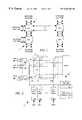
- FIG. 7illustrates routing arbitrator 22 of FIG. 2 in more detailed block diagram form.
- Arbitrator 22includes a set of 24 input port interface units A 0 -A 23 , a set of 24 output port interface units B 0 -B 23 , a state machine 100 , a memory controller 102 and a comparator 104 .
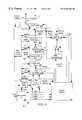
- FIG. 8is a flow chart illustrating the operation of state machine 100 .
- Memory controller 102receives the ID (INPORT) of an input port via a bus 116 and the ID (OUTPORT) of an output port via a bus 115 .
- state machine 100asserts an output MAKE signal
- memory controller 102writes data to RAM 14 of FIG. 2 causing switch 12 to make a data path connection between the input and output ports identified by the INPORT and OUTPORT IDs.
- state machine 100asserts an output BREAK signal
- memory controller 102writes data to RAM 14 causing switch 12 to break any data path connection to the output port identified by the OUTPORT ID.
- State machine 100periodically polls each output port interface circuit B 0 -B 23 to determine if the output port it serves is ready to receive a data packet and periodically polls each input port interface circuit A 0 -A 23 to determine if the input port it serves has a pending routing request.
- Comparator 104compares the ID of polled output port with the ID of an output port requested by a polled input port and asserts a MATCH signal input to state machine 100 when the IDs match, thereby telling state machine 100 when to establish a connection between the polled input and output ports.
- Each input port interface A 0 -A 23includes a routing request detector 106 and a set of tristate drivers 108 - 112 .
- a separate one of vertical lines V 0 -V 23is applied as input to the routing request detector 106 of each input port interface.
- the routing request detector 106looks for the code identifying a routing request appearing on the input vertical line from the input port accessing that vertical line, extracts the multiple bit ID (OUTPORT) of the output port conveyed in the routing request and supplies it as input to tristate driver 110 .
- Driver 110when enabled, places the requested OUTPORT ID on a multiple line bus 114 which conveys that OUTPORT ID to comparator 104 .
- Upon detecting an incoming request detector 106also asserts a request signal REQ applied to an input of driver 109 .
- driver 109When driver 109 is enabled, a single line bus 117 conveys the REQ signal to state machine 100 .
- the REQ signaltells state machine 100 when the input port has a pending connection request.
- the multiple bit ID (INPORT) of the input port making the requestis applied as input to tristate driver 111 .
- driver 111places the INPORT ID on bus 116 providing input to memory controller 102 .
- state machine 100sends a GRANT signal to the driver 108 of each input port interface A 0 -A 23 .
- State machine 100includes a set of 24 input port polling outputs IN( 0 )-IN( 23 ), each provided as the control input to the drivers 108 - 111 of a corresponding one of input port interface circuits A 0 -A 23 .
- state machine 100When polling a particular one of input port interface circuits A 0 -A 23 , state machine 100 asserts the corresponding enable signal IN( 0 )-IN( 23 ) to enable the interface circuit's drivers 108 - 111 .
- Each output port interface circuit B 0 -B 23includes an end of packet detector 120 , an S/R flip-flop 122 , and a set of tristate drivers 123 - 126 .
- State machine 100separately polls the output port interface circuits B 0 -B 23 using a set of 24 output signals OUT( 0 )-OUT( 23 ) to separately enable the tristate drivers 123 - 126 of each output port interface circuit.
- Each horizontal line H 0 -H 23 of FIG. 2is connected as input to the end of packet detector 120 of corresponding one of output port interface circuits B 0 -B 23 . When the end of packet detector 120 detects an end of transmission code on the horizontal line it sets flip-flop 122 to drive its Q output high.
- the Q outputis applied as an end of packet signal (EOT) input to driver 124 .
- Driver 124enabled when state machine 100 polls one of output port interfaces B 0 -B 23 , places the EOT signal on a bus line 130 providing input to state machine 100 .
- Tristate driver 126when enabled, places the OUTPORT ID of the output port served by the output port interface on bus lines 115 which convey that OUTPORT ID to comparator 104 and to memory controller 102 .
- state machine 100detects an asserted EOT signal, indicating that the polled output port interface circuit has received an end of transmission code, it asserts the BREAK signal, causing memory controller 102 to break the current connection to the polled output port identified by the OUTPORT ID on bus 115 .
- state machine 100assumes the polled output port is busy receiving a packet and does not make any new connection to it.
- the horizontal line H 0 -H 23 input to each output port interface circuit B 0 -B 23drives tristate driver 125 .
- driver 125when the output port T 0 -T 23 connected to the horizontal line H 0 -H 23 has a full packet buffer, it pulls down the horizontal line.
- driver 125When driver 125 is enabled, it pulls down a line 132 to provide a FULL signal input to state machine 100 . This tells state machine 100 not to establish a connection to the polled output port.
- state machine 100When, upon polling a pair of input and output port interface circuits, state machine 100 detects that the EOT and MATCH signals are asserted and the FULL signal is not asserted, its asserts the MAKE signal to cause memory controller 102 to make the requested connection between the polled input and output ports.
- the MAKE signalalso resets the flip-flop 122 of the polled output port interface circuit B 0 -B 23 via tristate driver 124 so that the Q output of flip-flop 122 indicates that the output port is now busy.
- FIG. 8is a flow chart illustrating the operation of state machine 100 of FIG. 7 .
- counters N and Mare set to 0 (step 140 ) and a variable FIRSTIN is set equal to M (step 142 ).
- a variable FIRSTINis set equal to M (step 142 ).
- State machine 100then increments the value of N (step 144 ) and asserts input and output port polling signals OUT(N) and IN(M) (step 146 ).
- step 148state machine 100 repeats steps 144 , 146 and 148 , incrementing N to poll the next output port interface circuit and checking for an asserted EOT signal.
- state machine 100detects a polled EOT signal at step 148 , it asserts the BREAK signal (step 150 ) causing memory controller 102 to break the connection to the polled output port. Thereafter, if the FULL signal output of the polled output port interface is asserted (step 151 ) state machine 100 returns to step 144 to poll a next output port.
- state machine 100When at step 151 state machine 100 detects that the FULL signal output of a polled output port interface is not asserted, it knows that the polled output port is not busy and does not have a full packet buffer. Thus (step 152 ) state machine 100 checks the REQ signal output of the polled input port interface circuit and the MATCH signal output of comparator 104 to determine if the polled input port is requesting a connection to the polled output port. If not, the value of M is incremented (step 154 ). If the value of M matches FIRSTIN (step 156 , then no input port is requesting the polled output port. In such case, state machine 100 reverts to step 144 to poll a next input port.
- step 156 Mdetermines whether the polled input port is requesting the polled output port.
- state machine 100When at step 152 state machine determines that the polled input port is requesting the polled output port, it asserts the MAKE signal (step 158 ) to signal memory controller 102 to make the connection between the polled input and output ports. State machine 100 then pulses the GRANT signal (step 160 ) to tell the polled input port interface circuit to send a connection response pulse back to the polled input port and to reset flip-flop 122 of the polled output port interface. After incrementing the value of M (step 162 ), state machine 100 returns to step 142 to reset the value of FIRSTIN to M. It then repeats the polling process to find a next grantable connection request. While the state machine operation is illustrated as a sequential polling process, those skilled in the art will appreciate that other types of arbitration processes may be employed including, for example, a parallel polling process in which ports are polled concurrently and the arbitration immediately services their port requests.
- a network switchhaving a zero latency flow control system for its output port buffers.
- the system as describeduses the same lines that interconnect the input and output ports through a crosspoint switch to convey routing requests and flow control signals from the input and output ports to a routing arbitrator that controls the crosspoint switch. This minimizes the number of I/O terminals each input and output port requires.
Landscapes
- Engineering & Computer Science (AREA)
- Computer Networks & Wireless Communication (AREA)
- Signal Processing (AREA)
- Data Exchanges In Wide-Area Networks (AREA)
- Small-Scale Networks (AREA)
Abstract
Description
| TABLE I | ||||
| Field | Field | Purpose | ||
| PREAMBLE | ||||
| 7 bytes | Used for synchronizing | |||
| START | 1 byte | Start of | ||
| DEST | ||||
| 6 bytes | Destination Network address | |||
| 6 bytes | Source Network address | |||
| TYPE/ | 2 bytes | Type or Length of data field | ||
| DATA | 46-1500 bytes | |||
| CRC | ||||
| 4 bytes | Frame check field | |||
| TABLE II | |||
| NIBBLE | 4B5B | ||
| 0000 | 11110 | ||
| 0001 | 01001 | ||
| 0010 | 10100 | ||
| 0011 | 10101 | ||
| 0100 | 01010 | ||
| 0101 | 01011 | ||
| 0110 | 01110 | ||
| 0111 | 01111 | ||
| 1000 | 10010 | ||
| 1001 | 10011 | ||
| 1010 | 10110 | ||
| 1011 | 10111 | ||
| 1100 | 11010 | ||
| 1101 | 11011 | ||
| 1110 | 11100 | ||
| 1111 | 11101 | ||
| TABLE III | ||||
| 4B5B | NAME | FUNCTION | ||
| 00000 | Q | TRANS_REQ Start | ||
| 11111 | I | Idle | ||
| 00100 | H | No Operation | ||
| 11000 | J | Packet Start 1 | ||
| 10001 | Packet Start | 2 | ||
| 01101 | T | End of Packet | ||
| 00111 | R | No Operation | ||
| 11001 | S | No Operation | ||
| 00001 | V | Violation | ||
| 00011 | V | Violation | ||
| 00010 | V | Violation | ||
| 00101 | V | Violation | ||
| 00110 | V | Violation | ||
| 01000 | V | Violation | ||
| 01100 | V | Violation | ||
| 10000 | CR | ROUTE_REQ Start | ||
Claims (13)
Priority Applications (1)
| Application Number | Priority Date | Filing Date | Title |
|---|---|---|---|
| US09/258,182US6636483B1 (en) | 1999-02-25 | 1999-02-25 | Network switch with zero latency flow control |
Applications Claiming Priority (1)
| Application Number | Priority Date | Filing Date | Title |
|---|---|---|---|
| US09/258,182US6636483B1 (en) | 1999-02-25 | 1999-02-25 | Network switch with zero latency flow control |
Publications (1)
| Publication Number | Publication Date |
|---|---|
| US6636483B1true US6636483B1 (en) | 2003-10-21 |
Family
ID=28791731
Family Applications (1)
| Application Number | Title | Priority Date | Filing Date |
|---|---|---|---|
| US09/258,182Expired - LifetimeUS6636483B1 (en) | 1999-02-25 | 1999-02-25 | Network switch with zero latency flow control |
Country Status (1)
| Country | Link |
|---|---|
| US (1) | US6636483B1 (en) |
Cited By (57)
| Publication number | Priority date | Publication date | Assignee | Title |
|---|---|---|---|---|
| US20040081108A1 (en)* | 2002-10-02 | 2004-04-29 | Andiamo Systems | Arbitration system |
| US20040100980A1 (en)* | 2002-11-26 | 2004-05-27 | Jacobs Mick R. | Apparatus and method for distributing buffer status information in a switching fabric |
| US6791969B1 (en)* | 1999-09-15 | 2004-09-14 | Lucent Technologies Inc. | Multiple input/output switch |
| US20060023716A1 (en)* | 1999-05-20 | 2006-02-02 | Advanced Micro Devices, Inc. | Bit bucket |
| US20060034307A1 (en)* | 2004-08-10 | 2006-02-16 | Fujitsu Limited | Method and apparatus for controlling storage of data |
| US20060123155A1 (en)* | 2004-11-16 | 2006-06-08 | Canon Kabushiki Kaisha | Data I/O apparatus |
| US7158510B1 (en)* | 2002-02-14 | 2007-01-02 | Alcatel | Look-up table arbitration system and method for a fast switching element |
| US7218632B1 (en)* | 2000-12-06 | 2007-05-15 | Cisco Technology, Inc. | Packet processing engine architecture |
| US20070268895A1 (en)* | 2006-05-19 | 2007-11-22 | Motorola, Inc. | Method and apparatus for switching data |
| US7359376B1 (en)* | 2000-11-20 | 2008-04-15 | Thomson Licensing | Serial compressed bus interface having a reduced pin count |
| US20090225775A1 (en)* | 2008-03-06 | 2009-09-10 | Integrated Device Technology, Inc. | Serial Buffer To Support Reliable Connection Between Rapid I/O End-Point And FPGA Lite-Weight Protocols |
| US20090225770A1 (en)* | 2008-03-06 | 2009-09-10 | Integrated Device Technology, Inc. | Method To Support Lossless Real Time Data Sampling And Processing On Rapid I/O End-Point |
| US20090228621A1 (en)* | 2008-03-06 | 2009-09-10 | Integrated Device Technology, Inc. | Protocol Translation In A Serial Buffer |
| US20090228630A1 (en)* | 2008-03-06 | 2009-09-10 | Integrated Device Technology, Inc. | Serial Buffer To Support Rapid I/O Logic Layer Out Of order Response With Data Retransmission |
| US20090225769A1 (en)* | 2008-03-06 | 2009-09-10 | Integrated Device Technology, Inc. | Method To Support Flexible Data Transport On Serial Protocols |
| US20090228733A1 (en)* | 2008-03-06 | 2009-09-10 | Integrated Device Technology, Inc. | Power Management On sRIO Endpoint |
| US20100161894A1 (en)* | 2004-10-29 | 2010-06-24 | Foundry Networks, Inc. | Double density content addressable memory (cam) lookup scheme |
| US7852768B1 (en) | 2006-06-21 | 2010-12-14 | Marvell International Ltd. | Physical-layer device management for network switches |
| US7876746B1 (en) | 2006-06-21 | 2011-01-25 | Marvell International Ltd. | Remote management for network switches |
| US7948872B2 (en) | 2000-11-17 | 2011-05-24 | Foundry Networks, Llc | Backplane interface adapter with error control and redundant fabric |
| US20110164616A1 (en)* | 2002-10-02 | 2011-07-07 | Andiamo Systems | Methods and apparatus for processing superframes |
| US7978614B2 (en) | 2007-01-11 | 2011-07-12 | Foundry Network, LLC | Techniques for detecting non-receipt of fault detection protocol packets |
| US7978702B2 (en) | 2000-11-17 | 2011-07-12 | Foundry Networks, Llc | Backplane interface adapter |
| US8037399B2 (en) | 2007-07-18 | 2011-10-11 | Foundry Networks, Llc | Techniques for segmented CRC design in high speed networks |
| US8090901B2 (en) | 2009-05-14 | 2012-01-03 | Brocade Communications Systems, Inc. | TCAM management approach that minimize movements |
| US8149839B1 (en) | 2007-09-26 | 2012-04-03 | Foundry Networks, Llc | Selection of trunk ports and paths using rotation |
| US8170044B2 (en) | 2002-05-06 | 2012-05-01 | Foundry Networks, Llc | Pipeline method and system for switching packets |
| US8194666B2 (en) | 2002-05-06 | 2012-06-05 | Foundry Networks, Llc | Flexible method for processing data packets in a network routing system for enhanced efficiency and monitoring capability |
| US20120155520A1 (en)* | 2007-10-16 | 2012-06-21 | Virtensys Limited | Data switch |
| US8238255B2 (en) | 2006-11-22 | 2012-08-07 | Foundry Networks, Llc | Recovering from failures without impact on data traffic in a shared bus architecture |
| US8271859B2 (en) | 2007-07-18 | 2012-09-18 | Foundry Networks Llc | Segmented CRC design in high speed networks |
| US8448162B2 (en) | 2005-12-28 | 2013-05-21 | Foundry Networks, Llc | Hitless software upgrades |
| US20130156043A1 (en)* | 2011-12-15 | 2013-06-20 | Micron Technology, Inc. | Methods and systems for routing in a state machine |
| US8493988B2 (en) | 2004-03-26 | 2013-07-23 | Foundry Networks, Llc | Method and apparatus for aggregating input data streams |
| US8599850B2 (en) | 2009-09-21 | 2013-12-03 | Brocade Communications Systems, Inc. | Provisioning single or multistage networks using ethernet service instances (ESIs) |
| US8671219B2 (en) | 2002-05-06 | 2014-03-11 | Foundry Networks, Llc | Method and apparatus for efficiently processing data packets in a computer network |
| US8718051B2 (en) | 2003-05-15 | 2014-05-06 | Foundry Networks, Llc | System and method for high speed packet transmission |
| US8730961B1 (en) | 2004-04-26 | 2014-05-20 | Foundry Networks, Llc | System and method for optimizing router lookup |
| US9448965B2 (en) | 2013-03-15 | 2016-09-20 | Micron Technology, Inc. | Receiving data streams in parallel and providing a first portion of data to a first state machine engine and a second portion to a second state machine |
| US9524248B2 (en) | 2012-07-18 | 2016-12-20 | Micron Technology, Inc. | Memory management for a hierarchical memory system |
| US9703574B2 (en) | 2013-03-15 | 2017-07-11 | Micron Technology, Inc. | Overflow detection and correction in state machine engines |
| US10019311B2 (en) | 2016-09-29 | 2018-07-10 | Micron Technology, Inc. | Validation of a symbol response memory |
| US10146555B2 (en) | 2016-07-21 | 2018-12-04 | Micron Technology, Inc. | Adaptive routing to avoid non-repairable memory and logic defects on automata processor |
| US10268602B2 (en) | 2016-09-29 | 2019-04-23 | Micron Technology, Inc. | System and method for individual addressing |
| US10417236B2 (en) | 2008-12-01 | 2019-09-17 | Micron Technology, Inc. | Devices, systems, and methods to synchronize simultaneous DMA parallel processing of a single data stream by multiple devices |
| US10430210B2 (en) | 2014-12-30 | 2019-10-01 | Micron Technology, Inc. | Systems and devices for accessing a state machine |
| US10592450B2 (en) | 2016-10-20 | 2020-03-17 | Micron Technology, Inc. | Custom compute cores in integrated circuit devices |
| US10684983B2 (en) | 2009-12-15 | 2020-06-16 | Micron Technology, Inc. | Multi-level hierarchical routing matrices for pattern-recognition processors |
| US10691964B2 (en) | 2015-10-06 | 2020-06-23 | Micron Technology, Inc. | Methods and systems for event reporting |
| US10769099B2 (en) | 2014-12-30 | 2020-09-08 | Micron Technology, Inc. | Devices for time division multiplexing of state machine engine signals |
| US10846103B2 (en) | 2015-10-06 | 2020-11-24 | Micron Technology, Inc. | Methods and systems for representing processing resources |
| US10929764B2 (en) | 2016-10-20 | 2021-02-23 | Micron Technology, Inc. | Boolean satisfiability |
| US10977309B2 (en) | 2015-10-06 | 2021-04-13 | Micron Technology, Inc. | Methods and systems for creating networks |
| US11023758B2 (en) | 2009-01-07 | 2021-06-01 | Micron Technology, Inc. | Buses for pattern-recognition processors |
| US11366675B2 (en) | 2014-12-30 | 2022-06-21 | Micron Technology, Inc. | Systems and devices for accessing a state machine |
| US11488645B2 (en) | 2012-04-12 | 2022-11-01 | Micron Technology, Inc. | Methods for reading data from a storage buffer including delaying activation of a column select |
| US12197510B2 (en) | 2016-10-20 | 2025-01-14 | Micron Technology, Inc. | Traversal of S portion of a graph problem to be solved using automata processor |
Citations (4)
| Publication number | Priority date | Publication date | Assignee | Title |
|---|---|---|---|---|
| US5838684A (en)* | 1996-02-22 | 1998-11-17 | Fujitsu, Ltd. | Low latency, high clock frequency plesioasynchronous packet-based crossbar switching chip system and method |
| US6208644B1 (en)* | 1998-03-12 | 2001-03-27 | I-Cube, Inc. | Network switch providing dynamic load balancing |
| US6212194B1 (en)* | 1998-08-05 | 2001-04-03 | I-Cube, Inc. | Network routing switch with non-blocking arbitration system |
| US6230229B1 (en)* | 1997-12-19 | 2001-05-08 | Storage Technology Corporation | Method and system for arbitrating path contention in a crossbar interconnect network |
- 1999
- 1999-02-25USUS09/258,182patent/US6636483B1/ennot_activeExpired - Lifetime
Patent Citations (4)
| Publication number | Priority date | Publication date | Assignee | Title |
|---|---|---|---|---|
| US5838684A (en)* | 1996-02-22 | 1998-11-17 | Fujitsu, Ltd. | Low latency, high clock frequency plesioasynchronous packet-based crossbar switching chip system and method |
| US6230229B1 (en)* | 1997-12-19 | 2001-05-08 | Storage Technology Corporation | Method and system for arbitrating path contention in a crossbar interconnect network |
| US6208644B1 (en)* | 1998-03-12 | 2001-03-27 | I-Cube, Inc. | Network switch providing dynamic load balancing |
| US6212194B1 (en)* | 1998-08-05 | 2001-04-03 | I-Cube, Inc. | Network routing switch with non-blocking arbitration system |
Cited By (116)
| Publication number | Priority date | Publication date | Assignee | Title |
|---|---|---|---|---|
| US20060023716A1 (en)* | 1999-05-20 | 2006-02-02 | Advanced Micro Devices, Inc. | Bit bucket |
| US6791969B1 (en)* | 1999-09-15 | 2004-09-14 | Lucent Technologies Inc. | Multiple input/output switch |
| US9030937B2 (en) | 2000-11-17 | 2015-05-12 | Foundry Networks, Llc | Backplane interface adapter with error control and redundant fabric |
| US8964754B2 (en) | 2000-11-17 | 2015-02-24 | Foundry Networks, Llc | Backplane interface adapter with error control and redundant fabric |
| US7978702B2 (en) | 2000-11-17 | 2011-07-12 | Foundry Networks, Llc | Backplane interface adapter |
| US7948872B2 (en) | 2000-11-17 | 2011-05-24 | Foundry Networks, Llc | Backplane interface adapter with error control and redundant fabric |
| US8514716B2 (en) | 2000-11-17 | 2013-08-20 | Foundry Networks, Llc | Backplane interface adapter with error control and redundant fabric |
| US8619781B2 (en) | 2000-11-17 | 2013-12-31 | Foundry Networks, Llc | Backplane interface adapter with error control and redundant fabric |
| US7359376B1 (en)* | 2000-11-20 | 2008-04-15 | Thomson Licensing | Serial compressed bus interface having a reduced pin count |
| US7218632B1 (en)* | 2000-12-06 | 2007-05-15 | Cisco Technology, Inc. | Packet processing engine architecture |
| US7158510B1 (en)* | 2002-02-14 | 2007-01-02 | Alcatel | Look-up table arbitration system and method for a fast switching element |
| US8671219B2 (en) | 2002-05-06 | 2014-03-11 | Foundry Networks, Llc | Method and apparatus for efficiently processing data packets in a computer network |
| US8194666B2 (en) | 2002-05-06 | 2012-06-05 | Foundry Networks, Llc | Flexible method for processing data packets in a network routing system for enhanced efficiency and monitoring capability |
| US8989202B2 (en) | 2002-05-06 | 2015-03-24 | Foundry Networks, Llc | Pipeline method and system for switching packets |
| US8170044B2 (en) | 2002-05-06 | 2012-05-01 | Foundry Networks, Llc | Pipeline method and system for switching packets |
| US20110164616A1 (en)* | 2002-10-02 | 2011-07-07 | Andiamo Systems | Methods and apparatus for processing superframes |
| US20040081108A1 (en)* | 2002-10-02 | 2004-04-29 | Andiamo Systems | Arbitration system |
| US7349416B2 (en)* | 2002-11-26 | 2008-03-25 | Cisco Technology, Inc. | Apparatus and method for distributing buffer status information in a switching fabric |
| US20040100980A1 (en)* | 2002-11-26 | 2004-05-27 | Jacobs Mick R. | Apparatus and method for distributing buffer status information in a switching fabric |
| US8811390B2 (en) | 2003-05-15 | 2014-08-19 | Foundry Networks, Llc | System and method for high speed packet transmission |
| US8718051B2 (en) | 2003-05-15 | 2014-05-06 | Foundry Networks, Llc | System and method for high speed packet transmission |
| US9461940B2 (en) | 2003-05-15 | 2016-10-04 | Foundry Networks, Llc | System and method for high speed packet transmission |
| US9338100B2 (en) | 2004-03-26 | 2016-05-10 | Foundry Networks, Llc | Method and apparatus for aggregating input data streams |
| US8493988B2 (en) | 2004-03-26 | 2013-07-23 | Foundry Networks, Llc | Method and apparatus for aggregating input data streams |
| US8730961B1 (en) | 2004-04-26 | 2014-05-20 | Foundry Networks, Llc | System and method for optimizing router lookup |
| US7817651B2 (en)* | 2004-08-10 | 2010-10-19 | Fujitsu Limited | Method and apparatus for controlling storage of data |
| US20060034307A1 (en)* | 2004-08-10 | 2006-02-16 | Fujitsu Limited | Method and apparatus for controlling storage of data |
| US7953922B2 (en) | 2004-10-29 | 2011-05-31 | Foundry Networks, Llc | Double density content addressable memory (CAM) lookup scheme |
| US7953923B2 (en) | 2004-10-29 | 2011-05-31 | Foundry Networks, Llc | Double density content addressable memory (CAM) lookup scheme |
| US20100161894A1 (en)* | 2004-10-29 | 2010-06-24 | Foundry Networks, Inc. | Double density content addressable memory (cam) lookup scheme |
| US7689737B2 (en)* | 2004-11-16 | 2010-03-30 | Canon Kabushiki Kaisha | Data I/O apparatus for outputting image data via a network |
| US20060123155A1 (en)* | 2004-11-16 | 2006-06-08 | Canon Kabushiki Kaisha | Data I/O apparatus |
| US8448162B2 (en) | 2005-12-28 | 2013-05-21 | Foundry Networks, Llc | Hitless software upgrades |
| US9378005B2 (en) | 2005-12-28 | 2016-06-28 | Foundry Networks, Llc | Hitless software upgrades |
| WO2007136924A3 (en)* | 2006-05-19 | 2008-05-08 | Motorola Inc | Method and apparatus for switching data |
| US20070268895A1 (en)* | 2006-05-19 | 2007-11-22 | Motorola, Inc. | Method and apparatus for switching data |
| US7876746B1 (en) | 2006-06-21 | 2011-01-25 | Marvell International Ltd. | Remote management for network switches |
| US7852768B1 (en) | 2006-06-21 | 2010-12-14 | Marvell International Ltd. | Physical-layer device management for network switches |
| US8238255B2 (en) | 2006-11-22 | 2012-08-07 | Foundry Networks, Llc | Recovering from failures without impact on data traffic in a shared bus architecture |
| US9030943B2 (en) | 2006-11-22 | 2015-05-12 | Foundry Networks, Llc | Recovering from failures without impact on data traffic in a shared bus architecture |
| US8155011B2 (en) | 2007-01-11 | 2012-04-10 | Foundry Networks, Llc | Techniques for using dual memory structures for processing failure detection protocol packets |
| US7978614B2 (en) | 2007-01-11 | 2011-07-12 | Foundry Network, LLC | Techniques for detecting non-receipt of fault detection protocol packets |
| US8395996B2 (en) | 2007-01-11 | 2013-03-12 | Foundry Networks, Llc | Techniques for processing incoming failure detection protocol packets |
| US9112780B2 (en) | 2007-01-11 | 2015-08-18 | Foundry Networks, Llc | Techniques for processing incoming failure detection protocol packets |
| US8037399B2 (en) | 2007-07-18 | 2011-10-11 | Foundry Networks, Llc | Techniques for segmented CRC design in high speed networks |
| US8271859B2 (en) | 2007-07-18 | 2012-09-18 | Foundry Networks Llc | Segmented CRC design in high speed networks |
| US8509236B2 (en) | 2007-09-26 | 2013-08-13 | Foundry Networks, Llc | Techniques for selecting paths and/or trunk ports for forwarding traffic flows |
| US8149839B1 (en) | 2007-09-26 | 2012-04-03 | Foundry Networks, Llc | Selection of trunk ports and paths using rotation |
| US8948192B2 (en)* | 2007-10-16 | 2015-02-03 | Micron Technology, Inc. | Data switch |
| US20120155520A1 (en)* | 2007-10-16 | 2012-06-21 | Virtensys Limited | Data switch |
| US8312241B2 (en) | 2008-03-06 | 2012-11-13 | Integrated Device Technology, Inc. | Serial buffer to support request packets with out of order response packets |
| US8312190B2 (en) | 2008-03-06 | 2012-11-13 | Integrated Device Technology, Inc. | Protocol translation in a serial buffer |
| US8625621B2 (en) | 2008-03-06 | 2014-01-07 | Integrated Device Technology, Inc. | Method to support flexible data transport on serial protocols |
| US8213448B2 (en)* | 2008-03-06 | 2012-07-03 | Integrated Device Technology, Inc. | Method to support lossless real time data sampling and processing on rapid I/O end-point |
| US20090228621A1 (en)* | 2008-03-06 | 2009-09-10 | Integrated Device Technology, Inc. | Protocol Translation In A Serial Buffer |
| US20090225769A1 (en)* | 2008-03-06 | 2009-09-10 | Integrated Device Technology, Inc. | Method To Support Flexible Data Transport On Serial Protocols |
| US20090225770A1 (en)* | 2008-03-06 | 2009-09-10 | Integrated Device Technology, Inc. | Method To Support Lossless Real Time Data Sampling And Processing On Rapid I/O End-Point |
| US20090225775A1 (en)* | 2008-03-06 | 2009-09-10 | Integrated Device Technology, Inc. | Serial Buffer To Support Reliable Connection Between Rapid I/O End-Point And FPGA Lite-Weight Protocols |
| US20090228630A1 (en)* | 2008-03-06 | 2009-09-10 | Integrated Device Technology, Inc. | Serial Buffer To Support Rapid I/O Logic Layer Out Of order Response With Data Retransmission |
| US20090228733A1 (en)* | 2008-03-06 | 2009-09-10 | Integrated Device Technology, Inc. | Power Management On sRIO Endpoint |
| US10838966B2 (en) | 2008-12-01 | 2020-11-17 | Micron Technology, Inc. | Devices, systems, and methods to synchronize simultaneous DMA parallel processing of a single data stream by multiple devices |
| US10417236B2 (en) | 2008-12-01 | 2019-09-17 | Micron Technology, Inc. | Devices, systems, and methods to synchronize simultaneous DMA parallel processing of a single data stream by multiple devices |
| US11023758B2 (en) | 2009-01-07 | 2021-06-01 | Micron Technology, Inc. | Buses for pattern-recognition processors |
| US12067767B2 (en) | 2009-01-07 | 2024-08-20 | Micron Technology, Inc. | Buses for pattern-recognition processors |
| US8090901B2 (en) | 2009-05-14 | 2012-01-03 | Brocade Communications Systems, Inc. | TCAM management approach that minimize movements |
| US9166818B2 (en) | 2009-09-21 | 2015-10-20 | Brocade Communications Systems, Inc. | Provisioning single or multistage networks using ethernet service instances (ESIs) |
| US8599850B2 (en) | 2009-09-21 | 2013-12-03 | Brocade Communications Systems, Inc. | Provisioning single or multistage networks using ethernet service instances (ESIs) |
| US10684983B2 (en) | 2009-12-15 | 2020-06-16 | Micron Technology, Inc. | Multi-level hierarchical routing matrices for pattern-recognition processors |
| US11226926B2 (en) | 2009-12-15 | 2022-01-18 | Micron Technology, Inc. | Multi-level hierarchical routing matrices for pattern-recognition processors |
| US11768798B2 (en) | 2009-12-15 | 2023-09-26 | Micron Technology, Inc. | Multi-level hierarchical routing matrices for pattern-recognition processors |
| US9535861B2 (en)* | 2011-12-15 | 2017-01-03 | Micron Technology, Inc. | Methods and systems for routing in a state machine |
| US20160239440A1 (en)* | 2011-12-15 | 2016-08-18 | Micron Technology, Inc. | Methods and systems for routing in a state machine |
| US20130156043A1 (en)* | 2011-12-15 | 2013-06-20 | Micron Technology, Inc. | Methods and systems for routing in a state machine |
| US8680888B2 (en)* | 2011-12-15 | 2014-03-25 | Micron Technologies, Inc. | Methods and systems for routing in a state machine |
| US20140204956A1 (en)* | 2011-12-15 | 2014-07-24 | Micron Technology, Inc. | Methods and systems for routing in a state machine |
| US9275290B2 (en)* | 2011-12-15 | 2016-03-01 | Micron Technology, Inc. | Methods and systems for routing in a state machine |
| US12347519B2 (en) | 2012-04-12 | 2025-07-01 | Micron Technology, Inc. | Methods for reading data from a storage buffer including delaying activation of a column select |
| US11488645B2 (en) | 2012-04-12 | 2022-11-01 | Micron Technology, Inc. | Methods for reading data from a storage buffer including delaying activation of a column select |
| US9524248B2 (en) | 2012-07-18 | 2016-12-20 | Micron Technology, Inc. | Memory management for a hierarchical memory system |
| US10089242B2 (en) | 2012-07-18 | 2018-10-02 | Micron Technology, Inc. | Memory management for a hierarchical memory system |
| US10831672B2 (en) | 2012-07-18 | 2020-11-10 | Micron Technology, Inc | Memory management for a hierarchical memory system |
| US11775320B2 (en) | 2013-03-15 | 2023-10-03 | Micron Technology, Inc. | Overflow detection and correction in state machine engines |
| US9448965B2 (en) | 2013-03-15 | 2016-09-20 | Micron Technology, Inc. | Receiving data streams in parallel and providing a first portion of data to a first state machine engine and a second portion to a second state machine |
| US10929154B2 (en) | 2013-03-15 | 2021-02-23 | Micron Technology, Inc. | Overflow detection and correction in state machine engines |
| US10372653B2 (en) | 2013-03-15 | 2019-08-06 | Micron Technology, Inc. | Apparatuses for providing data received by a state machine engine |
| US11016790B2 (en) | 2013-03-15 | 2021-05-25 | Micron Technology, Inc. | Overflow detection and correction in state machine engines |
| US10606787B2 (en) | 2013-03-15 | 2020-03-31 | Mircron Technology, Inc. | Methods and apparatuses for providing data received by a state machine engine |
| US9703574B2 (en) | 2013-03-15 | 2017-07-11 | Micron Technology, Inc. | Overflow detection and correction in state machine engines |
| US9747242B2 (en) | 2013-03-15 | 2017-08-29 | Micron Technology, Inc. | Methods and apparatuses for providing data received by a plurality of state machine engines |
| US10067901B2 (en) | 2013-03-15 | 2018-09-04 | Micron Technology, Inc. | Methods and apparatuses for providing data received by a state machine engine |
| US11947979B2 (en) | 2014-12-30 | 2024-04-02 | Micron Technology, Inc. | Systems and devices for accessing a state machine |
| US10769099B2 (en) | 2014-12-30 | 2020-09-08 | Micron Technology, Inc. | Devices for time division multiplexing of state machine engine signals |
| US11366675B2 (en) | 2014-12-30 | 2022-06-21 | Micron Technology, Inc. | Systems and devices for accessing a state machine |
| US12130774B2 (en) | 2014-12-30 | 2024-10-29 | Micron Technology, Inc. | Devices for time division multiplexing of state machine engine signals |
| US11580055B2 (en) | 2014-12-30 | 2023-02-14 | Micron Technology, Inc. | Devices for time division multiplexing of state machine engine signals |
| US10430210B2 (en) | 2014-12-30 | 2019-10-01 | Micron Technology, Inc. | Systems and devices for accessing a state machine |
| US10977309B2 (en) | 2015-10-06 | 2021-04-13 | Micron Technology, Inc. | Methods and systems for creating networks |
| US11816493B2 (en) | 2015-10-06 | 2023-11-14 | Micron Technology, Inc. | Methods and systems for representing processing resources |
| US12174888B2 (en) | 2015-10-06 | 2024-12-24 | Micron Technology, Inc. | Methods and systems for creating automata networks |
| US10846103B2 (en) | 2015-10-06 | 2020-11-24 | Micron Technology, Inc. | Methods and systems for representing processing resources |
| US11977902B2 (en) | 2015-10-06 | 2024-05-07 | Micron Technology, Inc. | Methods and systems for event reporting |
| US10691964B2 (en) | 2015-10-06 | 2020-06-23 | Micron Technology, Inc. | Methods and systems for event reporting |
| US10146555B2 (en) | 2016-07-21 | 2018-12-04 | Micron Technology, Inc. | Adaptive routing to avoid non-repairable memory and logic defects on automata processor |
| US10698697B2 (en) | 2016-07-21 | 2020-06-30 | Micron Technology, Inc. | Adaptive routing to avoid non-repairable memory and logic defects on automata processor |
| US10521366B2 (en) | 2016-09-29 | 2019-12-31 | Micron Technology, Inc. | System and method for individual addressing |
| US10949290B2 (en) | 2016-09-29 | 2021-03-16 | Micron Technology, Inc. | Validation of a symbol response memory |
| US10402265B2 (en) | 2016-09-29 | 2019-09-03 | Micron Technology, Inc. | Validation of a symbol response memory |
| US10339071B2 (en) | 2016-09-29 | 2019-07-02 | Micron Technology, Inc. | System and method for individual addressing |
| US10789182B2 (en) | 2016-09-29 | 2020-09-29 | Micron Technology, Inc. | System and method for individual addressing |
| US10268602B2 (en) | 2016-09-29 | 2019-04-23 | Micron Technology, Inc. | System and method for individual addressing |
| US10019311B2 (en) | 2016-09-29 | 2018-07-10 | Micron Technology, Inc. | Validation of a symbol response memory |
| US10592450B2 (en) | 2016-10-20 | 2020-03-17 | Micron Technology, Inc. | Custom compute cores in integrated circuit devices |
| US11829311B2 (en) | 2016-10-20 | 2023-11-28 | Micron Technology, Inc. | Custom compute cores in integrated circuit devices |
| US11194747B2 (en) | 2016-10-20 | 2021-12-07 | Micron Technology, Inc. | Custom compute cores in integrated circuit devices |
| US10929764B2 (en) | 2016-10-20 | 2021-02-23 | Micron Technology, Inc. | Boolean satisfiability |
| US12197510B2 (en) | 2016-10-20 | 2025-01-14 | Micron Technology, Inc. | Traversal of S portion of a graph problem to be solved using automata processor |
Similar Documents
| Publication | Publication Date | Title |
|---|---|---|
| US6636483B1 (en) | Network switch with zero latency flow control | |
| US6510138B1 (en) | Network switch with head of line input buffer queue clearing | |
| US6208644B1 (en) | Network switch providing dynamic load balancing | |
| US6249528B1 (en) | Network switch providing per virtual channel queuing for segmentation and reassembly | |
| US5784003A (en) | Network switch with broadcast support | |
| EP0954792B1 (en) | Network switch with arbitration system | |
| US8379524B1 (en) | Prioritization and preemption of data frames over a switching fabric | |
| US7385972B2 (en) | Fibre channel arbitrated loop bufferless switch circuitry to increase bandwidth without significant increase in cost | |
| US8798091B2 (en) | Fibre channel arbitrated loop bufferless switch circuitry to increase bandwidth without significant increase in cost | |
| US6373848B1 (en) | Architecture for a multi-port adapter with a single media access control (MAC) | |
| US6295281B1 (en) | Symmetric flow control for ethernet full duplex buffered repeater | |
| US5291482A (en) | High bandwidth packet switch | |
| US6345310B1 (en) | Architecture for a multiple port adapter having a single media access control (MAC) with a single I/O port | |
| EP0054077A1 (en) | Method of transmitting information between stations attached to a unidirectional transmission ring | |
| US7701949B1 (en) | System and method for switching high priority traffic with low latency | |
| JPS6342542A (en) | Spatial dividing switch of data packet and method of exchanging data packets | |
| KR100708425B1 (en) | Apparatus and method for sharing memory using a single ring data bus connection configuration | |
| US5420853A (en) | Self controlling crossbar switch and method | |
| JPH10285208A (en) | Packet exchange integrated circuit |
Legal Events
| Date | Code | Title | Description |
|---|---|---|---|
| AS | Assignment | Owner name:I-CUBE, INC., CALIFORNIA Free format text:ASSIGNMENT OF ASSIGNORS INTEREST;ASSIGNOR:PANNELL, DONALD ROBERT;REEL/FRAME:009810/0263 Effective date:19990224 | |
| AS | Assignment | Owner name:FAIRCHILD SEMICONDUCTOR CORPORATION, MASSACHUSETTS Free format text:ASSIGNMENT OF ASSIGNORS INTEREST;ASSIGNOR:I-CUBE, INC.;REEL/FRAME:012961/0584 Effective date:20020520 | |
| STCF | Information on status: patent grant | Free format text:PATENTED CASE | |
| FEPP | Fee payment procedure | Free format text:PAYOR NUMBER ASSIGNED (ORIGINAL EVENT CODE: ASPN); ENTITY STATUS OF PATENT OWNER: LARGE ENTITY | |
| FPAY | Fee payment | Year of fee payment:4 | |
| FPAY | Fee payment | Year of fee payment:8 | |
| AS | Assignment | Owner name:RPX CORPORATION, CALIFORNIA Free format text:ASSIGNMENT OF ASSIGNORS INTEREST;ASSIGNOR:FAIRCHILD SEMICONDUCTOR CORPORATION;REEL/FRAME:026582/0631 Effective date:20110624 | |
| FPAY | Fee payment | Year of fee payment:12 | |
| AS | Assignment | Owner name:JEFFERIES FINANCE LLC, NEW YORK Free format text:SECURITY INTEREST;ASSIGNOR:RPX CORPORATION;REEL/FRAME:046486/0433 Effective date:20180619 | |
| AS | Assignment | Owner name:RPX CORPORATION, CALIFORNIA Free format text:RELEASE BY SECURED PARTY;ASSIGNOR:JEFFERIES FINANCE LLC;REEL/FRAME:054486/0422 Effective date:20201023 |