US6634826B1 - Clamp for support and connection members - Google Patents
Clamp for support and connection membersDownload PDFInfo
- Publication number
- US6634826B1 US6634826B1US09/516,037US51603700AUS6634826B1US 6634826 B1US6634826 B1US 6634826B1US 51603700 AUS51603700 AUS 51603700AUS 6634826 B1US6634826 B1US 6634826B1
- Authority
- US
- United States
- Prior art keywords
- pin
- knob
- additional
- hollow body
- spring
- Prior art date
- Legal status (The legal status is an assumption and is not a legal conclusion. Google has not performed a legal analysis and makes no representation as to the accuracy of the status listed.)
- Expired - Fee Related
Links
Images


Classifications
- B—PERFORMING OPERATIONS; TRANSPORTING
- B65—CONVEYING; PACKING; STORING; HANDLING THIN OR FILAMENTARY MATERIAL
- B65G—TRANSPORT OR STORAGE DEVICES, e.g. CONVEYORS FOR LOADING OR TIPPING, SHOP CONVEYOR SYSTEMS OR PNEUMATIC TUBE CONVEYORS
- B65G21/00—Supporting or protective framework or housings for endless load-carriers or traction elements of belt or chain conveyors
- B65G21/20—Means incorporated in, or attached to, framework or housings for guiding load-carriers, traction elements or loads supported on moving surfaces
- B65G21/2045—Mechanical means for guiding or retaining the load on the load-carrying surface
- B65G21/2063—Mechanical means for guiding or retaining the load on the load-carrying surface comprising elements not movable in the direction of load-transport
- B65G21/2072—Laterial guidance means
- Y—GENERAL TAGGING OF NEW TECHNOLOGICAL DEVELOPMENTS; GENERAL TAGGING OF CROSS-SECTIONAL TECHNOLOGIES SPANNING OVER SEVERAL SECTIONS OF THE IPC; TECHNICAL SUBJECTS COVERED BY FORMER USPC CROSS-REFERENCE ART COLLECTIONS [XRACs] AND DIGESTS
- Y10—TECHNICAL SUBJECTS COVERED BY FORMER USPC
- Y10T—TECHNICAL SUBJECTS COVERED BY FORMER US CLASSIFICATION
- Y10T24/00—Buckles, buttons, clasps, etc.
- Y10T24/39—Cord and rope holders
- Y10T24/3984—Alignable aperture and spring pressed moving element
- Y—GENERAL TAGGING OF NEW TECHNOLOGICAL DEVELOPMENTS; GENERAL TAGGING OF CROSS-SECTIONAL TECHNOLOGIES SPANNING OVER SEVERAL SECTIONS OF THE IPC; TECHNICAL SUBJECTS COVERED BY FORMER USPC CROSS-REFERENCE ART COLLECTIONS [XRACs] AND DIGESTS
- Y10—TECHNICAL SUBJECTS COVERED BY FORMER USPC
- Y10T—TECHNICAL SUBJECTS COVERED BY FORMER US CLASSIFICATION
- Y10T24/00—Buckles, buttons, clasps, etc.
- Y10T24/45—Separable-fastener or required component thereof [e.g., projection and cavity to complete interlock]
- Y10T24/45225—Separable-fastener or required component thereof [e.g., projection and cavity to complete interlock] including member having distinct formations and mating member selectively interlocking therewith
- Y10T24/45602—Receiving member includes either movable connection between interlocking components or variable configuration cavity
- Y10T24/45723—Receiving member includes either movable connection between interlocking components or variable configuration cavity having slidably connected, nonself-biasing interlocking component
- Y10T24/45743—Requiring manual force thereon to interlock or disengage
- Y10T24/45754—Requiring manual force thereon to interlock or disengage having closed aperture therethrough alignable with parallel access opening
- Y—GENERAL TAGGING OF NEW TECHNOLOGICAL DEVELOPMENTS; GENERAL TAGGING OF CROSS-SECTIONAL TECHNOLOGIES SPANNING OVER SEVERAL SECTIONS OF THE IPC; TECHNICAL SUBJECTS COVERED BY FORMER USPC CROSS-REFERENCE ART COLLECTIONS [XRACs] AND DIGESTS
- Y10—TECHNICAL SUBJECTS COVERED BY FORMER USPC
- Y10T—TECHNICAL SUBJECTS COVERED BY FORMER US CLASSIFICATION
- Y10T403/00—Joints and connections
- Y10T403/59—Manually releaseable latch type
- Y10T403/599—Spring biased manipulator
- Y—GENERAL TAGGING OF NEW TECHNOLOGICAL DEVELOPMENTS; GENERAL TAGGING OF CROSS-SECTIONAL TECHNOLOGIES SPANNING OVER SEVERAL SECTIONS OF THE IPC; TECHNICAL SUBJECTS COVERED BY FORMER USPC CROSS-REFERENCE ART COLLECTIONS [XRACs] AND DIGESTS
- Y10—TECHNICAL SUBJECTS COVERED BY FORMER USPC
- Y10T—TECHNICAL SUBJECTS COVERED BY FORMER US CLASSIFICATION
- Y10T403/00—Joints and connections
- Y10T403/60—Biased catch or latch
Definitions
- This inventionrelates to a clamp for support and connection members such as pins and the like, particularly but not exclusively as used in conveyor belts for supporting the relative guides, for example lateral guides.
- the main object of the inventionis therefore to provide a clamp which eliminates the need to use screw means for locking the clamped piece or component (such as a pin) by using for its tightening the action of elastic means and for its slackening a manual action counteracting that of said elastic means.
- Another object of the inventionis to provide a clamp in which its tightening is achieved by the action of elastic means and its slackening by a manual counteraction which locks the clamp in the slackened position (in which the required adjustment can be made), from which tightening can be again achieved by releasing the clamp from this position.
- a further object of the inventionis to provide a clamp in which it is easier and quicker to position the clamped piece or pin and adjust the length of that portion thereof which projects from the clamp.
- a further object of the inventionis to provide a cross-type clamp in which the tightening and slackening procedures of the two preceding objects apply to at least one of these members.
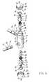
- FIG. 1is a perspective view of a first embodiment of a clamp of the invention
- FIG. 2is a side view of the body of the clamp of FIG. 1;
- FIG. 3is an enlarged side view of the upper part of FIG. 2;
- FIG. 4is an enlarged section through the lower part of the body of FIG. 2;
- FIG. 5is a perspective view of a second embodiment of the clamp according to the invention.
- FIG. 6is a perspective view of a third embodiment of the clamp according to the invention.
- the clamp of the illustrated embodimentcomprises an approximately cylindrical outer body 1 constructed of a known plastic, for example an engineering polymer.
- the bodyhas an axial bore which in its upper portion 2 (on the drawing) has a polygonal cross-section, for example hexagonal.
- This upper portionis followed by a substantially circular lower portion 3 (on the drawing) of diameter such that the two portions 2 and 3 meet at a step 4 .
- the lower portion 3has a terminal part 5 also of circular section but of reduced diameter.
- the outer body 1has an upper extension 1 A of lesser outer diameter than the remaining part.
- the body 1also comprises two diametrically opposing coaxial equal rectangular apertures 8 and two axially spaced-apart equal coaxial circular holes, their common axis lying at 90° to the common axis of said rectangular apertures.
- aperturesand “bores” are used interchangeably herein. It is to be understood that the term “coaxially bore” and “coaxially aperture” when used herein refers to the apertures/bores 8 and 9 in the drawings.
- the body 1houses:
- a washer 39preferably upwardly (with reference to FIG. 1) convex which rests on the step 4 and serves as a support for
- a member 11having a transverse circular through hole 12 (preferably comprising at its mid length an annular projection 13 ) and, at the opposite end to that on which the spring bears, an appendix 14 provided with one or more annular projections 15 , the member 11 having a polygonal cross-section which mates with that of the upper portion 2 of the bore through the body 1 so as to be able to slide therein but not rotate;
- a snap ring 16which is inserted into an inner annular groove 17 in the body 1 to retain the aforesaid internal parts ( 9 to 11 ) with in the body.
- knob 18On the appendix 14 of the member 11 there is snap-fitted in known manner a knob 18 in such a manner that it can rotate about said member 11 but cannot move axially on it.
- knob 18Transversely to and radially within the knob 18 , which is of engineering polymer, there are positioned two mutually coaxial metal pegs 19 located to penetrate respectively into the profiled guide apertures 6 and 7 provided in the extension 1 A of the body 1 . These pegs are shown outside the knob 18 in FIG. 1 .
- the member 11moves upwards (with reference to the drawing) under the action of the spring 10 , with the result that the through hole loses its coaxiality with the holes 9 of the body 1 , the projection 13 in the member 11 penetrates into the desired groove ( 31 ) of the pin 30 , and this latter is locked in position.
- the size of the through hole 12 at the relative annular projection 13must be such as to enable the pin 30 to pass when the through hole 12 is substantially coaxial with the holes 9 of the body 1 and, when in the locked (ie non-coaxial) state, enable the annular projection 11 to enter the groove 31 in the pin 30 and this latter to lock against the upper (with reference to the drawing) edges of the holes 9 .
- the member 11must be mounted in the body 1 such that the relative through hole 12 lies on the same side as the holes 9 of the body 1 .
- a circular rod 50is to be clamped by the screw knob 51 instead of the section bar of FIG. 1 .
- circular apertures 52are provided instead of the rectangular apertures 8 .
- the scope of the inventionalso includes a clamp which excludes those parts used to clamp the section bar 21 and the rod 50 , and hence limited to those parts relative to clamping the pin 30 and to maintaining it in its released position (for adjustment purposes).
- the scope of the inventionalso includes an embodiment in which for clamping and releasing (and maintaining the released position of) a section bar or a rod 50 , those parts provided for this purpose for the pin 30 and already described in detail are used.
- FIG. 6shows a third embodiment of the clamp according to the invention which includes a hollow body ( 1 ) of the clamp assembly includes an additional coaxial bore ( 9 ) and an additional spring ( 10 ) arranged within the hollow body ( 1 ).
- FIG. 6also reveals that an additional slidable but not rotatable member ( 11 ) is mounted in the hollow body ( 1 ), and is loaded by the additional spring ( 10 ), the additional member ( 11 ) having a through hole ( 12 ) aligning with the bore ( 9 ) formed in the hollow body ( 1 ).
- the through hole ( 12 )is receives at least one pin such that the pin is insertable through the additional member ( 11 ) and the hollow body ( 1 ).
- the knob ( 18 )has a first position in which the knob ( 18 ) is moved against action of the additional spring ( 10 ) such that the pin is released and a second position in which the additional knob ( 18 ) is locked by the action of the additional spring ( 10 ) such that the pin is locked.
- the scope of the inventionalso includes different means for locking the knob 18 in the position which enables the pin 30 to be moved than those already described.
- These locking meanscould for example comprise a peg 41 (FIG. 1) to be inserted into through holes 42 , 43 (FIGS. 1 and 3) provided in the lateral wall 18 A of the knob 18 and of the extension 1 A of the body 1 .
- These through holes 42 , 43are provided such that when the knob is in the position which enables the pin 30 to move, they are mutually coaxial, so enabling the peg 41 to be inserted to lock the knob.
- the pin 30comprises along its body a plurality of preferably recessed equidistant reference lines 44 (shown dashed in FIG. 1 ). These reference lines simplify and facilitate the operations required to adjust the length of that pin portion projecting from the clamp. In this respect, when a conveyor belt has to handle products, such as bottles, of different dimensions from the previously handled products, the position of all the pins has to be adjusted. The presence of the reference lines on the pin considerably facilitates this operation.
- the linesare made distinguishable from each other by marking each with a different recognition sign 70 such as, a different number or a different colour.
Landscapes
- Engineering & Computer Science (AREA)
- Mechanical Engineering (AREA)
- Clamps And Clips (AREA)
- Supports For Pipes And Cables (AREA)
- Load-Engaging Elements For Cranes (AREA)
- Snaps, Bayonet Connections, Set Pins, And Snap Rings (AREA)
- Mutual Connection Of Rods And Tubes (AREA)
- Insertion Pins And Rivets (AREA)
Abstract
Description
Claims (7)
Applications Claiming Priority (2)
| Application Number | Priority Date | Filing Date | Title |
|---|---|---|---|
| ITMI990397U | 1999-06-17 | ||
| IT1999MI000397UIT246799Y1 (en) | 1999-06-17 | 1999-06-17 | CLAMP FOR SUPPORT AND CONNECTION BODIES |
Publications (1)
| Publication Number | Publication Date |
|---|---|
| US6634826B1true US6634826B1 (en) | 2003-10-21 |
Family
ID=11382066
Family Applications (1)
| Application Number | Title | Priority Date | Filing Date |
|---|---|---|---|
| US09/516,037Expired - Fee RelatedUS6634826B1 (en) | 1999-06-17 | 2000-03-01 | Clamp for support and connection members |
Country Status (7)
| Country | Link |
|---|---|
| US (1) | US6634826B1 (en) |
| EP (1) | EP1061015B1 (en) |
| AT (1) | ATE393107T1 (en) |
| CA (1) | CA2299965C (en) |
| DE (1) | DE60038654T2 (en) |
| ES (1) | ES2304916T3 (en) |
| IT (1) | IT246799Y1 (en) |
Cited By (9)
| Publication number | Priority date | Publication date | Assignee | Title |
|---|---|---|---|---|
| US20080048480A1 (en)* | 2004-05-26 | 2008-02-28 | Stefano Liviero | Armrest/Backrest Support Bracket For Chairs, In Particular Office Chairs |
| US20080086959A1 (en)* | 2006-10-17 | 2008-04-17 | Mcnelis David Michael | Storm shutter |
| US20080168632A1 (en)* | 2007-01-11 | 2008-07-17 | Andrea Andreoli | Clamp For Supporting Bar Of Components Of Conveyors Of Articles |
| US20080216447A1 (en)* | 2007-03-05 | 2008-09-11 | Tian-Tsz Hung | Positioning Device For Window Frame |
| US20100006584A1 (en)* | 2008-07-14 | 2010-01-14 | Michelli Richard D | Methods and apparatus for dispensing solid articles |
| US20130174437A1 (en)* | 2010-09-08 | 2013-07-11 | Metso Paper Sweden Ab | Positioning device for a drain pipe in a drying cylinder |
| US8944415B2 (en) | 2011-04-05 | 2015-02-03 | Dorel Juvenile Group, Inc. | Security enclosure |
| US9534406B2 (en)* | 2014-10-01 | 2017-01-03 | Paratech, Incorporated | Adjustable strut with locking mechanism |
| CN115348940A (en)* | 2020-03-30 | 2022-11-15 | 弗莱林克有限公司 | Conveyor guide rail accessory |
Families Citing this family (2)
| Publication number | Priority date | Publication date | Assignee | Title |
|---|---|---|---|---|
| IT249849Y1 (en) | 2000-07-18 | 2003-06-05 | System Plast Stampaggio Tecnop | CLAMP FOR SUPPORT AND CONNECTION BODIES |
| EP1840050B1 (en)* | 2006-03-29 | 2010-09-01 | Transmisiones Mecánicas AVE, S.A. | Device for adjusting a railing |
Citations (19)
| Publication number | Priority date | Publication date | Assignee | Title |
|---|---|---|---|---|
| US942780A (en)* | 1909-06-08 | 1909-12-07 | Mesta Machine Co | Coupling device. |
| US1204457A (en)* | 1914-05-04 | 1916-11-14 | Archibald Lewis Kreeft | Electric binding-post. |
| US3080867A (en)* | 1958-05-22 | 1963-03-12 | Eichinger Maximilian | Clamping device |
| US3103352A (en)* | 1961-02-14 | 1963-09-10 | Arnold M Steffen | Work holder |
| US3806860A (en)* | 1972-12-07 | 1974-04-23 | D Flammini | Electrical binding post |
| GB1597992A (en) | 1977-02-28 | 1981-09-16 | Stork Bepak Bv | Conveyor |
| US4354410A (en)* | 1977-12-06 | 1982-10-19 | Potomac Applied Mechanics, Inc. | Straight line insulation cutter assembly |
| US4726615A (en)* | 1986-08-27 | 1988-02-23 | Goldberg Lewis B | Disc handling device |
| US4884914A (en)* | 1988-05-23 | 1989-12-05 | Shultz William E | Adjustable and lockable screw spindle support device |
| US5078310A (en)* | 1991-01-28 | 1992-01-07 | Ferry Delois M | Mechanically retained fish stringer assembly |
| US5186197A (en)* | 1992-07-06 | 1993-02-16 | Lavine Edward L | Collapsible umbrella handle |
| DE4242119A1 (en) | 1992-12-14 | 1994-06-16 | Kettler Heinz Gmbh | Telescoping pipe arrangement - has profiled region of inner and outer pipe, form fitting and pressed together via fixture device |
| US5323514A (en)* | 1992-05-20 | 1994-06-28 | Yoshida Kogyo K. K. | Cord stopper |
| US5335782A (en) | 1993-05-13 | 1994-08-09 | Herzog Kenneth J | Conveyor post rail clamp |
| US5501544A (en)* | 1994-11-10 | 1996-03-26 | Nolu Plastics, Inc. | Three-piece clamping assembly |
| CA2211915A1 (en) | 1996-08-19 | 1998-02-19 | John P. Williamson | Quick-change guide rail support |
| WO1998018697A1 (en) | 1996-10-29 | 1998-05-07 | Tetra Laval Holdings & Finance S.A. | A method and an apparatus for regulating the width between two support railings along a straight conveyor |
| CA2269107A1 (en)* | 1998-04-27 | 1999-10-27 | System Plast Stampaggio Tecnopolimeri S.N.C. Di Alberto Marsetti & C. | Clamping member for at least one support pin for belt conveyor components |
| US6126359A (en)* | 1997-02-25 | 2000-10-03 | Karl Storz Gmbh & Co. Kg | Bayonet coupling for detachable joining of two tubular shaft instruments or instrument parts |
- 1999
- 1999-06-17ITIT1999MI000397Upatent/IT246799Y1/enactive
- 2000
- 2000-02-24EPEP00103411Apatent/EP1061015B1/ennot_activeExpired - Lifetime
- 2000-02-24DEDE60038654Tpatent/DE60038654T2/ennot_activeExpired - Lifetime
- 2000-02-24ATAT00103411Tpatent/ATE393107T1/ennot_activeIP Right Cessation
- 2000-02-24ESES00103411Tpatent/ES2304916T3/ennot_activeExpired - Lifetime
- 2000-03-01USUS09/516,037patent/US6634826B1/ennot_activeExpired - Fee Related
- 2000-03-03CACA002299965Apatent/CA2299965C/ennot_activeExpired - Fee Related
Patent Citations (21)
| Publication number | Priority date | Publication date | Assignee | Title |
|---|---|---|---|---|
| US942780A (en)* | 1909-06-08 | 1909-12-07 | Mesta Machine Co | Coupling device. |
| US1204457A (en)* | 1914-05-04 | 1916-11-14 | Archibald Lewis Kreeft | Electric binding-post. |
| US3080867A (en)* | 1958-05-22 | 1963-03-12 | Eichinger Maximilian | Clamping device |
| US3103352A (en)* | 1961-02-14 | 1963-09-10 | Arnold M Steffen | Work holder |
| US3806860A (en)* | 1972-12-07 | 1974-04-23 | D Flammini | Electrical binding post |
| GB1597992A (en) | 1977-02-28 | 1981-09-16 | Stork Bepak Bv | Conveyor |
| US4354410A (en)* | 1977-12-06 | 1982-10-19 | Potomac Applied Mechanics, Inc. | Straight line insulation cutter assembly |
| US4726615A (en)* | 1986-08-27 | 1988-02-23 | Goldberg Lewis B | Disc handling device |
| US4884914A (en)* | 1988-05-23 | 1989-12-05 | Shultz William E | Adjustable and lockable screw spindle support device |
| US5078310A (en)* | 1991-01-28 | 1992-01-07 | Ferry Delois M | Mechanically retained fish stringer assembly |
| US5323514A (en)* | 1992-05-20 | 1994-06-28 | Yoshida Kogyo K. K. | Cord stopper |
| US5186197A (en)* | 1992-07-06 | 1993-02-16 | Lavine Edward L | Collapsible umbrella handle |
| DE4242119A1 (en) | 1992-12-14 | 1994-06-16 | Kettler Heinz Gmbh | Telescoping pipe arrangement - has profiled region of inner and outer pipe, form fitting and pressed together via fixture device |
| US5335782A (en) | 1993-05-13 | 1994-08-09 | Herzog Kenneth J | Conveyor post rail clamp |
| US5501544A (en)* | 1994-11-10 | 1996-03-26 | Nolu Plastics, Inc. | Three-piece clamping assembly |
| CA2211915A1 (en) | 1996-08-19 | 1998-02-19 | John P. Williamson | Quick-change guide rail support |
| US6003662A (en)* | 1996-08-19 | 1999-12-21 | Fenner, Inc. | Quick-change guide rail support |
| WO1998018697A1 (en) | 1996-10-29 | 1998-05-07 | Tetra Laval Holdings & Finance S.A. | A method and an apparatus for regulating the width between two support railings along a straight conveyor |
| US6126359A (en)* | 1997-02-25 | 2000-10-03 | Karl Storz Gmbh & Co. Kg | Bayonet coupling for detachable joining of two tubular shaft instruments or instrument parts |
| CA2269107A1 (en)* | 1998-04-27 | 1999-10-27 | System Plast Stampaggio Tecnopolimeri S.N.C. Di Alberto Marsetti & C. | Clamping member for at least one support pin for belt conveyor components |
| US6260245B1 (en)* | 1998-04-27 | 2001-07-17 | System Plast S.P.A. | Clamping member for at least one support pin for belt conveyor components |
Cited By (13)
| Publication number | Priority date | Publication date | Assignee | Title |
|---|---|---|---|---|
| US7819482B2 (en)* | 2004-05-26 | 2010-10-26 | Imarc S.P.A. | Armrest/backrest support bracket for chairs, in particular office chairs |
| US20080048480A1 (en)* | 2004-05-26 | 2008-02-28 | Stefano Liviero | Armrest/Backrest Support Bracket For Chairs, In Particular Office Chairs |
| US20080086959A1 (en)* | 2006-10-17 | 2008-04-17 | Mcnelis David Michael | Storm shutter |
| US20080168632A1 (en)* | 2007-01-11 | 2008-07-17 | Andrea Andreoli | Clamp For Supporting Bar Of Components Of Conveyors Of Articles |
| US8015675B2 (en) | 2007-01-11 | 2011-09-13 | Rexnord Marbett S.R.L. | Clamp for supporting bar of components of conveyors of articles |
| US20080216447A1 (en)* | 2007-03-05 | 2008-09-11 | Tian-Tsz Hung | Positioning Device For Window Frame |
| US20100006584A1 (en)* | 2008-07-14 | 2010-01-14 | Michelli Richard D | Methods and apparatus for dispensing solid articles |
| US8499967B2 (en)* | 2008-07-14 | 2013-08-06 | Parata Systems, Llc | Methods and apparatus for dispensing solid articles |
| US8770437B2 (en) | 2008-07-14 | 2014-07-08 | Parata Systems, Llc | Methods and apparatus for dispensing solid articles |
| US20130174437A1 (en)* | 2010-09-08 | 2013-07-11 | Metso Paper Sweden Ab | Positioning device for a drain pipe in a drying cylinder |
| US8944415B2 (en) | 2011-04-05 | 2015-02-03 | Dorel Juvenile Group, Inc. | Security enclosure |
| US9534406B2 (en)* | 2014-10-01 | 2017-01-03 | Paratech, Incorporated | Adjustable strut with locking mechanism |
| CN115348940A (en)* | 2020-03-30 | 2022-11-15 | 弗莱林克有限公司 | Conveyor guide rail accessory |
Also Published As
| Publication number | Publication date |
|---|---|
| ATE393107T1 (en) | 2008-05-15 |
| EP1061015A1 (en) | 2000-12-20 |
| DE60038654D1 (en) | 2008-06-05 |
| ES2304916T3 (en) | 2008-11-01 |
| IT246799Y1 (en) | 2002-04-10 |
| CA2299965A1 (en) | 2000-12-17 |
| EP1061015B1 (en) | 2008-04-23 |
| DE60038654T2 (en) | 2009-06-04 |
| ITMI990397V0 (en) | 1999-06-17 |
| CA2299965C (en) | 2007-09-25 |
| ITMI990397U1 (en) | 2000-12-17 |
Similar Documents
| Publication | Publication Date | Title |
|---|---|---|
| US6634826B1 (en) | Clamp for support and connection members | |
| DE69735490T2 (en) | CLAMP AS A BRACKET FOR A WUNDSPERRER | |
| EP1595641B1 (en) | Clamping assembly having a chuck and a pallet releasably mounted thereon | |
| EP2918379B1 (en) | Coupling device for a handling device | |
| EP1723343B1 (en) | Device for mutual positioning of longitudinal building components | |
| US6260245B1 (en) | Clamping member for at least one support pin for belt conveyor components | |
| US6065737A (en) | Tensioning device | |
| EP1344494A2 (en) | Aiming apparatus for locking nail | |
| DE19842090A1 (en) | Fluid pressure chuck | |
| DE102014001963B4 (en) | Clamping device for reproducible, accurate clamping of workpieces | |
| US20230338218A1 (en) | Equalizer clamp assembly, system and method | |
| US9829019B2 (en) | Swiveling taper lock connector | |
| US10836005B2 (en) | Locating pin assembly | |
| EP3366417B1 (en) | Pull bolt of a zero point clamping system | |
| EP2215374B1 (en) | A ball steering pin assembly for reduced wear and method therefor | |
| DE19805833A1 (en) | Connector to fasten handling appliance to support structure | |
| EP3203090A1 (en) | Locking unit | |
| US4230328A (en) | Device for connecting an ejection pin of an injection molding tool or the like to an ejector device | |
| CA2353515C (en) | Clamp for support and connection members | |
| DE102016201690B4 (en) | Adaptation element, add-on system, handling system, motor vehicle and method for mounting an add-on part to a supporting structure | |
| DE102004011579A1 (en) | Chucks for clamping bit to power tool, comprising front and rear clamping sphere engaging with clamping sleeve | |
| EP1607641B1 (en) | Fastening assembly | |
| EP1574293B1 (en) | Sliding joint | |
| EP3246118B1 (en) | Tool carrier | |
| DE102016111640B3 (en) | sensor housing |
Legal Events
| Date | Code | Title | Description |
|---|---|---|---|
| AS | Assignment | Owner name:SYSTEM PLAST STAMPAGGIO TECNOPOLIMERI S.N.C. DI AL Free format text:ASSIGNMENT OF ASSIGNORS INTEREST;ASSIGNOR:MARSETTI, SERGIO;REEL/FRAME:010599/0840 Effective date:20000218 | |
| AS | Assignment | Owner name:SYSTEM PLAST S.P.A., ITALY Free format text:CHANGE OF NAME;ASSIGNOR:SYSTEM PLAST S.N.C. DI MARSETTI & C. STAMPAGGIO TECNOPOLIMERI;REEL/FRAME:011722/0550 Effective date:20010316 | |
| FPAY | Fee payment | Year of fee payment:4 | |
| REFU | Refund | Free format text:REFUND - PAYMENT OF MAINTENANCE FEE, 8TH YR, SMALL ENTITY (ORIGINAL EVENT CODE: R2552); ENTITY STATUS OF PATENT OWNER: LARGE ENTITY | |
| FPAY | Fee payment | Year of fee payment:8 | |
| SULP | Surcharge for late payment | ||
| REMI | Maintenance fee reminder mailed | ||
| LAPS | Lapse for failure to pay maintenance fees | ||
| REIN | Reinstatement after maintenance fee payment confirmed | ||
| FEPP | Fee payment procedure | Free format text:PETITION RELATED TO MAINTENANCE FEES FILED (ORIGINAL EVENT CODE: PMFP); ENTITY STATUS OF PATENT OWNER: LARGE ENTITY | |
| REFU | Refund | Free format text:REFUND - PAYMENT OF MAINTENANCE FEE UNDER 1.28(C) (ORIGINAL EVENT CODE: R1559); ENTITY STATUS OF PATENT OWNER: LARGE ENTITY | |
| FEPP | Fee payment procedure | Free format text:PETITION RELATED TO MAINTENANCE FEES GRANTED (ORIGINAL EVENT CODE: PMFG); ENTITY STATUS OF PATENT OWNER: LARGE ENTITY | |
| REFU | Refund | Free format text:REFUND - PAYMENT OF MAINTENANCE FEE UNDER 1.28(C) (ORIGINAL EVENT CODE: R1559); ENTITY STATUS OF PATENT OWNER: LARGE ENTITY | |
| FP | Lapsed due to failure to pay maintenance fee | Effective date:20111021 | |
| PRDP | Patent reinstated due to the acceptance of a late maintenance fee | Effective date:20120501 | |
| REMI | Maintenance fee reminder mailed | ||
| LAPS | Lapse for failure to pay maintenance fees | ||
| STCH | Information on status: patent discontinuation | Free format text:PATENT EXPIRED DUE TO NONPAYMENT OF MAINTENANCE FEES UNDER 37 CFR 1.362 | |
| FP | Lapsed due to failure to pay maintenance fee | Effective date:20151021 |