US6634804B1 - Camera enclosure wall mount - Google Patents
Camera enclosure wall mountDownload PDFInfo
- Publication number
- US6634804B1 US6634804B1US10/298,023US29802302AUS6634804B1US 6634804 B1US6634804 B1US 6634804B1US 29802302 AUS29802302 AUS 29802302AUS 6634804 B1US6634804 B1US 6634804B1
- Authority
- US
- United States
- Prior art keywords
- rotatable member
- camera
- support apparatus
- socket
- camera support
- Prior art date
- Legal status (The legal status is an assumption and is not a legal conclusion. Google has not performed a legal analysis and makes no representation as to the accuracy of the status listed.)
- Expired - Lifetime
Links
Images


Classifications
- F—MECHANICAL ENGINEERING; LIGHTING; HEATING; WEAPONS; BLASTING
- F16—ENGINEERING ELEMENTS AND UNITS; GENERAL MEASURES FOR PRODUCING AND MAINTAINING EFFECTIVE FUNCTIONING OF MACHINES OR INSTALLATIONS; THERMAL INSULATION IN GENERAL
- F16M—FRAMES, CASINGS OR BEDS OF ENGINES, MACHINES OR APPARATUS, NOT SPECIFIC TO ENGINES, MACHINES OR APPARATUS PROVIDED FOR ELSEWHERE; STANDS; SUPPORTS
- F16M13/00—Other supports for positioning apparatus or articles; Means for steadying hand-held apparatus or articles
- F16M13/02—Other supports for positioning apparatus or articles; Means for steadying hand-held apparatus or articles for supporting on, or attaching to, an object, e.g. tree, gate, window-frame, cycle
- F—MECHANICAL ENGINEERING; LIGHTING; HEATING; WEAPONS; BLASTING
- F16—ENGINEERING ELEMENTS AND UNITS; GENERAL MEASURES FOR PRODUCING AND MAINTAINING EFFECTIVE FUNCTIONING OF MACHINES OR INSTALLATIONS; THERMAL INSULATION IN GENERAL
- F16M—FRAMES, CASINGS OR BEDS OF ENGINES, MACHINES OR APPARATUS, NOT SPECIFIC TO ENGINES, MACHINES OR APPARATUS PROVIDED FOR ELSEWHERE; STANDS; SUPPORTS
- F16M11/00—Stands or trestles as supports for apparatus or articles placed thereon ; Stands for scientific apparatus such as gravitational force meters
- F16M11/02—Heads
- F16M11/04—Means for attachment of apparatus; Means allowing adjustment of the apparatus relatively to the stand
- F16M11/06—Means for attachment of apparatus; Means allowing adjustment of the apparatus relatively to the stand allowing pivoting
- F16M11/10—Means for attachment of apparatus; Means allowing adjustment of the apparatus relatively to the stand allowing pivoting around a horizontal axis
- F—MECHANICAL ENGINEERING; LIGHTING; HEATING; WEAPONS; BLASTING
- F16—ENGINEERING ELEMENTS AND UNITS; GENERAL MEASURES FOR PRODUCING AND MAINTAINING EFFECTIVE FUNCTIONING OF MACHINES OR INSTALLATIONS; THERMAL INSULATION IN GENERAL
- F16M—FRAMES, CASINGS OR BEDS OF ENGINES, MACHINES OR APPARATUS, NOT SPECIFIC TO ENGINES, MACHINES OR APPARATUS PROVIDED FOR ELSEWHERE; STANDS; SUPPORTS
- F16M11/00—Stands or trestles as supports for apparatus or articles placed thereon ; Stands for scientific apparatus such as gravitational force meters
- F16M11/20—Undercarriages with or without wheels
- F16M11/2007—Undercarriages with or without wheels comprising means allowing pivoting adjustment
- F16M11/2014—Undercarriages with or without wheels comprising means allowing pivoting adjustment around a vertical axis
Definitions
- the present inventionrelates to surveillance camera systems, and more particularly to an adjustable surface-mountable support for a surveillance camera that provides for a wide range of adjustability while providing protection for the wires passing through the interior thereof.
- surveillance camerashave become increasingly widespread. Often, such cameras must be mounted outdoors where they may be subjected to dramatic temperature, moisture and other climactic changes, as well as potential vandalism. Accordingly, different enclosures and support structures have been developed for surveillance cameras. Unfortunately, the designs of many existing support structures allow the wires leading from the camera to be exposed to the outside where they can be damaged or cut. In addition, many existing camera supports cannot support large cameras and provide only a very limited range of adjustment of the position of the attached camera.
- the present inventionprovides a superior sealed aesthetically pleasing surveillance camera support structure that maintains the camera wires on the inside, and provides wide range of positioning and viewing angles even when a large or heavy camera is attached.
- the inventionincludes a surface-mountable base and a reinforced outwardly-extending support arm.
- a specially adapted rotatable swivel mechanismis attached at the end of the arm that is capable of being rotated (the panning or scanning angle) through a horizontal arc of as much as approximately 300°.
- Adjacent to the swivelis another rotatable joint that is capable of moving up and down (the tilt angle) through an arc of as much as approximately 180°.
- a camera support platformis attached above the rotatable joint.
- the support structureis designed so that once the viewing angle for the camera is selected, the swivel and joint are tightened so that the camera remains pointing at this fixed angle.
- significant bearing surfacesare provided in the swivel and joint so as to maximize the frictional resistance to movement.
- sufficient spaceis provided inside both the swivel and joint to allow wires leading from the camera to pass through. Wires exiting the camera pass through the support platform, rotatable joint, swivel, arm and base into an opening provided in the surface behind where the mount is attached.
- the present inventionalso allows considerable adjustability and flexibility with respect to establishing and changing the viewing angle of the attached camera, while keeping the sensitive internal components shielded from outside contaminants. Establishing and changing the viewing angle is accomplished by loosening the tightening screws of the swivel and/or joint, moving the camera to the desired angle, and then retightening these screws.
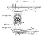
- FIG. 1is a top perspective exterior view of the present invention.
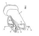
- FIG. 2is a bottom perspective exterior view of the present invention.
- FIG. 3is a sectional view of the upper portion of the invention along line A—A of FIG. 1
- FIG. 4is a partially exploded sectional view of the arm and swivel of the invention along line A—A of FIG. 1
- FIG. 5is a sectional view of the assembled invention along line A—A of FIG. 1
- FIG. 6is a partially exploded sectional view of the invention along line B—B of FIG. 1
- FIG. 7is a sectional view of the assembled invention along line A—A of FIG. 1 showing the wire path.
- FIG. 8is a sectional view of the assembled invention along line B—B of FIG. 1 showing the wire path.
- FIG. 9is a side view of the invention supporting a large camera and enclosure that has been tilted down 90°.
- FIG. 10is a side view of the invention supporting a large camera and enclosure that has been tilted up about 6°.
- FIG. 11is a set of three views (side, perspective and top) of the invention supporting a large camera enclosure, each view showing the same camera angle rotated 159° from the front.
- the support structure of the present inventionincludes a surface-mountable base or plate 11 for attachment to a flat surface such as a wall, ceiling, soffit or shelf; a hollow reinforced arm 12 fixedly attachable to mounting plate 11 ; a rotatable member 34 for adjustable engagement with a socket 21 at the end of arm 12 ; and upper journal member 40 for adjustable engagement with the rotatable member 34 ; and an upper platform 19 for holding the surveillance camera. Hollow or open areas are provided in side each of these members to allow wires 15 to be threaded through on the inside from the mounting surface to the camera.
- a socket 21is provided at the end of arm 12 for engagement with a mating structure 30 on a separate rotatable member 34 .
- Socket 21includes an upwardly extending annular lip 22 having an outer angled bearing surface 23 as shown in FIG. 4.
- a through hole 25is provided in the center of socket 21 for receiving an attachment means such as a screw 26 .
- An open interior area 24is provided at the bottom of socket 21 that is in communication with the hollow interior 13 of arm 12 through which one or more wires 15 may be threaded. See FIGS. 6-8 for wiring.
- Rotatable member 34includes a bell-shaped lower journal section 30 having an angled annular interior surface 31 for slidable engagement against surface 23 of socket 21 as shown in FIG. 4 and 5.
- a receptacle and opening 29is provided at the center of journal section 30 for receiving attachment screw 26 , which also provides a pivot for rotation of member 34 .
- An open interior area 38is provided in journal section 30 for receiving one or more wires 15 .
- Journal section 30is inserted over socket 21 and rotated to a desired location, as surfaces 23 and 31 bear against each other. When the desired position is reached, screw 26 is tightened in order to fix this position.
- the area of surfaces 23 and 31is deliberately large to provide sufficient friction to hold a heavy camera in the selected position.
- the upper portion of rotatable member 34includes a hemispherical cup 35 having an axis that is perpendicular to that of bell-shaped journal section 30 .
- the interior of cup 35includes annular angled bearing surface 36 for receiving a journal member 41 of an upper support.
- a through hole 45is provided in the center of cup 35 for receiving an attachment means such as a screw 43 .
- Open interior area 38opens into cup 35 providing a channel between journal section 30 and cup 35 through which one or more wires 15 may be threaded.
- An upper support member 40is provided for holding the surveillance camera of the system as shown in FIGS. 3 and 5.
- Support member 40has a lower journal member 41 in the form of an annular lip having an angled bearing surface 44 for slidable engagement against surface 36 of hemispherical cup 35 of rotatable member 34 .
- An opening 42is provided at the center of journal member 41 for receiving attachment screw 43 which also serves as a pivot for rotation of journal member 41 .
- An open interior area 48is provided in journal member 41 for receiving one or more wires 15 .
- Area 48provides a channel to the interior of upper platform 19 so that wires 15 may be threaded to the camera. See FIG. 7
- Journal member 41is inserted into cup 35 and rotated to a desired location, as surfaces 44 and 36 bear against each other. When the desired position is reached, screw 43 is tightened in order to fix this position.
- the area of surfaces 44 and 36is deliberately large to provide sufficient friction to hold a heavy camera in the selected position.
- FIGS. 9 and 10Some exemplary tilt angles for the camera are illustrated in FIGS. 9 and 10.
- FIG. 9shows a camera enclosure 18 tilted straight down, a full 90° from the horizontal axis of the arm 12 .
- FIG. 10shows the same enclosure tilted upward at about 6°. It is to be appreciated that a large camera enclosure 18 is shown in these illustrations, and that smaller enclosures will allow for a much wider range of tilt angles, up to a full 180°.
- FIG. 11shows a rotation (pan or scan) angle using the same large camera enclosure 18 with viewing window 17 .
- the counter-clockwise range of rotationis about 159° (180° ⁇ 21°) from the angle of arm 12 .
- the same range of rotation(about 159°) is available in the clockwise direction, for a full range of well over 300°.
- a large camera enclosure 18is shown in FIG. 11, and that smaller enclosures will allow for an even wider range of rotation (pan/scan) angles.
Landscapes
- Engineering & Computer Science (AREA)
- General Engineering & Computer Science (AREA)
- Mechanical Engineering (AREA)
- Studio Devices (AREA)
- Accessories Of Cameras (AREA)
Abstract
Description
Claims (8)
Priority Applications (2)
| Application Number | Priority Date | Filing Date | Title |
|---|---|---|---|
| US10/298,023US6634804B1 (en) | 2002-11-15 | 2002-11-15 | Camera enclosure wall mount |
| US10/654,837US6824318B2 (en) | 2002-11-15 | 2003-09-03 | Camera enclosure wall mount |
Applications Claiming Priority (1)
| Application Number | Priority Date | Filing Date | Title |
|---|---|---|---|
| US10/298,023US6634804B1 (en) | 2002-11-15 | 2002-11-15 | Camera enclosure wall mount |
Related Child Applications (1)
| Application Number | Title | Priority Date | Filing Date |
|---|---|---|---|
| US10/654,837ContinuationUS6824318B2 (en) | 2002-11-15 | 2003-09-03 | Camera enclosure wall mount |
Publications (1)
| Publication Number | Publication Date |
|---|---|
| US6634804B1true US6634804B1 (en) | 2003-10-21 |
Family
ID=28791791
Family Applications (2)
| Application Number | Title | Priority Date | Filing Date |
|---|---|---|---|
| US10/298,023Expired - LifetimeUS6634804B1 (en) | 2002-11-15 | 2002-11-15 | Camera enclosure wall mount |
| US10/654,837Expired - LifetimeUS6824318B2 (en) | 2002-11-15 | 2003-09-03 | Camera enclosure wall mount |
Family Applications After (1)
| Application Number | Title | Priority Date | Filing Date |
|---|---|---|---|
| US10/654,837Expired - LifetimeUS6824318B2 (en) | 2002-11-15 | 2003-09-03 | Camera enclosure wall mount |
Country Status (1)
| Country | Link |
|---|---|
| US (2) | US6634804B1 (en) |
Cited By (38)
| Publication number | Priority date | Publication date | Assignee | Title |
|---|---|---|---|---|
| US20040096209A1 (en)* | 2002-11-15 | 2004-05-20 | Toste David L.A. | Camera enclosure wall mount |
| US20060147194A1 (en)* | 2005-01-03 | 2006-07-06 | Jones Theodore L | Connect/disconnect mechanism for a surveillance camera head |
| EP1788800A4 (en)* | 2004-05-07 | 2009-09-23 | Panasonic Corp | CAMERA INSTALLATION FACILITY |
| US7762731B2 (en) | 2008-09-12 | 2010-07-27 | Pelco, Inc. | Environmentally sealed enclosure |
| US20140191098A1 (en)* | 2013-01-07 | 2014-07-10 | Qsc Audio Products, Llc | Adjustable mounting assembly |
| US20150139635A1 (en)* | 2013-11-20 | 2015-05-21 | Axis Ab | Mounting bracket |
| US9454820B1 (en) | 2015-06-12 | 2016-09-27 | Google Inc. | Using a scene illuminating infrared emitter array in a video monitoring camera for depth determination |
| US9489745B1 (en) | 2015-06-12 | 2016-11-08 | Google Inc. | Using depth maps of a scene to identify movement of a video camera |
| US9537968B1 (en) | 2012-01-06 | 2017-01-03 | Google Inc. | Communication of socket protocol based data over a storage protocol based interface |
| US9544485B2 (en) | 2015-05-27 | 2017-01-10 | Google Inc. | Multi-mode LED illumination system |
| US9549124B2 (en) | 2015-06-12 | 2017-01-17 | Google Inc. | Day and night detection based on one or more of illuminant detection, lux level detection, and tiling |
| US9553910B2 (en) | 2012-01-06 | 2017-01-24 | Google Inc. | Backfill of video stream |
| US9554063B2 (en) | 2015-06-12 | 2017-01-24 | Google Inc. | Using infrared images of a monitored scene to identify windows |
| US9554064B2 (en) | 2015-06-12 | 2017-01-24 | Google Inc. | Using a depth map of a monitored scene to identify floors, walls, and ceilings |
| US9626849B2 (en) | 2015-06-12 | 2017-04-18 | Google Inc. | Using scene information from a security camera to reduce false security alerts |
| USD802647S1 (en) | 2011-10-28 | 2017-11-14 | Google Inc. | Camera stand |
| US9886620B2 (en) | 2015-06-12 | 2018-02-06 | Google Llc | Using a scene illuminating infrared emitter array in a video monitoring camera to estimate the position of the camera |
| USD818026S1 (en)* | 2017-02-25 | 2018-05-15 | Amcrest Global Holdings Limited | Camera |
| US10008003B2 (en) | 2015-06-12 | 2018-06-26 | Google Llc | Simulating an infrared emitter array in a video monitoring camera to construct a lookup table for depth determination |
| USD824446S1 (en)* | 2017-02-25 | 2018-07-31 | Amcrest Global Holdings Limited | Camera |
| USD824447S1 (en)* | 2017-03-23 | 2018-07-31 | Shenzhen Dericam Technology Co., Ltd. | Network camera |
| USD825638S1 (en)* | 2016-07-22 | 2018-08-14 | Avigilon Corporation | Dome camera with pendant adapter |
| US10148918B1 (en)* | 2015-04-06 | 2018-12-04 | Position Imaging, Inc. | Modular shelving systems for package tracking |
| US10180615B2 (en) | 2016-10-31 | 2019-01-15 | Google Llc | Electrochromic filtering in a camera |
| US10455364B2 (en) | 2016-12-12 | 2019-10-22 | Position Imaging, Inc. | System and method of personalized navigation inside a business enterprise |
| US10582095B2 (en) | 2016-10-14 | 2020-03-03 | MP High Tech Solutions Pty Ltd | Imaging apparatuses and enclosures |
| US10634503B2 (en) | 2016-12-12 | 2020-04-28 | Position Imaging, Inc. | System and method of personalized navigation inside a business enterprise |
| US10634506B2 (en) | 2016-12-12 | 2020-04-28 | Position Imaging, Inc. | System and method of personalized navigation inside a business enterprise |
| US10853757B1 (en) | 2015-04-06 | 2020-12-01 | Position Imaging, Inc. | Video for real-time confirmation in package tracking systems |
| US11089232B2 (en) | 2019-01-11 | 2021-08-10 | Position Imaging, Inc. | Computer-vision-based object tracking and guidance module |
| US11120392B2 (en) | 2017-01-06 | 2021-09-14 | Position Imaging, Inc. | System and method of calibrating a directional light source relative to a camera's field of view |
| CN113811926A (en)* | 2019-03-11 | 2021-12-17 | 奥布罗(私人股份)有限公司 | Camera mounting arrangement |
| US11361536B2 (en) | 2018-09-21 | 2022-06-14 | Position Imaging, Inc. | Machine-learning-assisted self-improving object-identification system and method |
| US11416805B1 (en) | 2015-04-06 | 2022-08-16 | Position Imaging, Inc. | Light-based guidance for package tracking systems |
| US11436553B2 (en) | 2016-09-08 | 2022-09-06 | Position Imaging, Inc. | System and method of object tracking using weight confirmation |
| US11501244B1 (en) | 2015-04-06 | 2022-11-15 | Position Imaging, Inc. | Package tracking systems and methods |
| US11765323B2 (en) | 2017-05-26 | 2023-09-19 | Calumino Pty Ltd. | Apparatus and method of location determination in a thermal imaging system |
| US12190542B2 (en) | 2017-01-06 | 2025-01-07 | Position Imaging, Inc. | System and method of calibrating a directional light source relative to a camera's field of view |
Families Citing this family (9)
| Publication number | Priority date | Publication date | Assignee | Title |
|---|---|---|---|---|
| GB2420702B (en)* | 2005-12-03 | 2007-04-04 | Ason Cctv Industry Co Ltd | Support bracket for camera housing system |
| US8194132B2 (en) | 2006-01-20 | 2012-06-05 | Old World Industries, Llc | System for monitoring an area adjacent a vehicle |
| USD577050S1 (en) | 2006-01-20 | 2008-09-16 | Intellectual Solutions, Inc. | Mountable camera |
| US20070276250A1 (en)* | 2006-05-03 | 2007-11-29 | General Electric Company | Medical device mounting system |
| US20100046937A1 (en)* | 2006-10-16 | 2010-02-25 | Mteye Security Ltd. | Device and system for preset field-of-view imaging |
| US20090201412A1 (en)* | 2008-02-07 | 2009-08-13 | Ament Jr Robert Merle | Outdoor Camera Cage |
| USD634345S1 (en)* | 2010-06-07 | 2011-03-15 | Cnb Technology Inc. | Camera for closed circuit television |
| USD691187S1 (en)* | 2012-01-20 | 2013-10-08 | Lg Electronics Inc. | Security camera |
| USD723603S1 (en)* | 2013-09-06 | 2015-03-03 | Wirepath Home Systems, Llc | Surveillance camera |
Citations (23)
| Publication number | Priority date | Publication date | Assignee | Title |
|---|---|---|---|---|
| US3568583A (en) | 1968-05-13 | 1971-03-09 | Charles Horberg Jr | Surveillance camera device and controls therefor |
| US4320949A (en) | 1976-03-03 | 1982-03-23 | Pagano Raymond V | Weatherized housing assembly for camera |
| US4736218A (en) | 1985-10-24 | 1988-04-05 | M.S.E. Engineering Systems Ltd. | Camera support and housing |
| US4974088A (en) | 1988-05-13 | 1990-11-27 | Maruwa Electronic & Chemical Company | Remote control apparatus for a rotating television camera base |
| USD325212S (en) | 1989-07-17 | 1992-04-07 | Elbex Video Kabushiki Kaisha | Casing for TV camera |
| US5115263A (en) | 1990-03-15 | 1992-05-19 | Videor Technical E. Hartig Gmbh | Protective casing for optical instruments |
| US5214245A (en) | 1990-03-15 | 1993-05-25 | Videor Technical E. Hartig Gmbh | Protective casing for optical instruments |
| US5224675A (en) | 1991-11-01 | 1993-07-06 | Pelco | Mounting apparatus |
| USD340940S (en) | 1991-11-01 | 1993-11-02 | Pelco | Combined camera mount and camera housing |
| USD349714S (en) | 1991-11-18 | 1994-08-16 | Elmo Company Ltd. | Surveillance camera |
| US5394208A (en) | 1993-10-22 | 1995-02-28 | Eastman Kodak Company | Environmental enclosure for a camera |
| US5649256A (en)* | 1996-05-29 | 1997-07-15 | Fifty Cycle Video Laser Device Co. Ltd. | Adjustable means for a monitor camera |
| US5689304A (en) | 1996-03-04 | 1997-11-18 | Philips Electronic North America Corporation | Indoor/outdoor surveillance housing |
| US5790910A (en) | 1997-08-04 | 1998-08-04 | Peerless Industries, Inc. | Camera mounting apparatus |
| US5818519A (en) | 1996-01-17 | 1998-10-06 | Wren; Clifford T. | Surveillance camera mounting apparatus |
| US5850579A (en) | 1997-06-09 | 1998-12-15 | Addco, Inc. | Pan/tilt support with concentric drive shafts |
| USD403340S (en) | 1998-01-26 | 1998-12-29 | Pelco | Camera enclosure |
| USD424087S (en) | 1999-02-19 | 2000-05-02 | Philips Electronics North America Corporation | Pendant mounted surveillance camera housing |
| US6061087A (en) | 1998-07-16 | 2000-05-09 | Sensormatic Electronics Corporation | Outdoor enclosure for video surveillance system |
| US6203216B1 (en) | 1996-11-29 | 2001-03-20 | Canon Kabushiki Kaisha | Compact low-profile camera device |
| USD446534S1 (en) | 1999-03-18 | 2001-08-14 | Gunther S. Zimmer | Swiveling housing |
| US6354749B1 (en) | 1998-09-09 | 2002-03-12 | Videolarm, Inc. | Housing for surveillance camera |
| US6375369B1 (en) | 1999-04-22 | 2002-04-23 | Videolarm, Inc. | Housing for a surveillance camera |
Family Cites Families (7)
| Publication number | Priority date | Publication date | Assignee | Title |
|---|---|---|---|---|
| US3877041A (en)* | 1972-06-12 | 1975-04-08 | Vera Jean Graeter | First person camera system |
| US4797736A (en)* | 1987-09-02 | 1989-01-10 | Luxtec Corporation | Head mounted illumination and camera assembly |
| US5844985A (en)* | 1995-09-22 | 1998-12-01 | Qualcomm Incorporated | Vertically correcting antenna for portable telephone handsets |
| USD398319S (en) | 1997-10-06 | 1998-09-15 | Achiever Shredders and Office Products Company | Security camera |
| DE60028815T2 (en)* | 1999-12-23 | 2006-10-05 | Hill-Rom Services, Inc., Wilmington | OPERATING ROOM SYSTEM |
| USD446236S1 (en) | 2000-07-03 | 2001-08-07 | Chia-Teh Chen | Pattern projector |
| US6634804B1 (en)* | 2002-11-15 | 2003-10-21 | Pelco | Camera enclosure wall mount |
- 2002
- 2002-11-15USUS10/298,023patent/US6634804B1/ennot_activeExpired - Lifetime
- 2003
- 2003-09-03USUS10/654,837patent/US6824318B2/ennot_activeExpired - Lifetime
Patent Citations (23)
| Publication number | Priority date | Publication date | Assignee | Title |
|---|---|---|---|---|
| US3568583A (en) | 1968-05-13 | 1971-03-09 | Charles Horberg Jr | Surveillance camera device and controls therefor |
| US4320949A (en) | 1976-03-03 | 1982-03-23 | Pagano Raymond V | Weatherized housing assembly for camera |
| US4736218A (en) | 1985-10-24 | 1988-04-05 | M.S.E. Engineering Systems Ltd. | Camera support and housing |
| US4974088A (en) | 1988-05-13 | 1990-11-27 | Maruwa Electronic & Chemical Company | Remote control apparatus for a rotating television camera base |
| USD325212S (en) | 1989-07-17 | 1992-04-07 | Elbex Video Kabushiki Kaisha | Casing for TV camera |
| US5115263A (en) | 1990-03-15 | 1992-05-19 | Videor Technical E. Hartig Gmbh | Protective casing for optical instruments |
| US5214245A (en) | 1990-03-15 | 1993-05-25 | Videor Technical E. Hartig Gmbh | Protective casing for optical instruments |
| US5224675A (en) | 1991-11-01 | 1993-07-06 | Pelco | Mounting apparatus |
| USD340940S (en) | 1991-11-01 | 1993-11-02 | Pelco | Combined camera mount and camera housing |
| USD349714S (en) | 1991-11-18 | 1994-08-16 | Elmo Company Ltd. | Surveillance camera |
| US5394208A (en) | 1993-10-22 | 1995-02-28 | Eastman Kodak Company | Environmental enclosure for a camera |
| US5818519A (en) | 1996-01-17 | 1998-10-06 | Wren; Clifford T. | Surveillance camera mounting apparatus |
| US5689304A (en) | 1996-03-04 | 1997-11-18 | Philips Electronic North America Corporation | Indoor/outdoor surveillance housing |
| US5649256A (en)* | 1996-05-29 | 1997-07-15 | Fifty Cycle Video Laser Device Co. Ltd. | Adjustable means for a monitor camera |
| US6203216B1 (en) | 1996-11-29 | 2001-03-20 | Canon Kabushiki Kaisha | Compact low-profile camera device |
| US5850579A (en) | 1997-06-09 | 1998-12-15 | Addco, Inc. | Pan/tilt support with concentric drive shafts |
| US5790910A (en) | 1997-08-04 | 1998-08-04 | Peerless Industries, Inc. | Camera mounting apparatus |
| USD403340S (en) | 1998-01-26 | 1998-12-29 | Pelco | Camera enclosure |
| US6061087A (en) | 1998-07-16 | 2000-05-09 | Sensormatic Electronics Corporation | Outdoor enclosure for video surveillance system |
| US6354749B1 (en) | 1998-09-09 | 2002-03-12 | Videolarm, Inc. | Housing for surveillance camera |
| USD424087S (en) | 1999-02-19 | 2000-05-02 | Philips Electronics North America Corporation | Pendant mounted surveillance camera housing |
| USD446534S1 (en) | 1999-03-18 | 2001-08-14 | Gunther S. Zimmer | Swiveling housing |
| US6375369B1 (en) | 1999-04-22 | 2002-04-23 | Videolarm, Inc. | Housing for a surveillance camera |
Cited By (90)
| Publication number | Priority date | Publication date | Assignee | Title |
|---|---|---|---|---|
| US20040096209A1 (en)* | 2002-11-15 | 2004-05-20 | Toste David L.A. | Camera enclosure wall mount |
| US6824318B2 (en)* | 2002-11-15 | 2004-11-30 | Pelco | Camera enclosure wall mount |
| EP1788800A4 (en)* | 2004-05-07 | 2009-09-23 | Panasonic Corp | CAMERA INSTALLATION FACILITY |
| US20060147194A1 (en)* | 2005-01-03 | 2006-07-06 | Jones Theodore L | Connect/disconnect mechanism for a surveillance camera head |
| US7217045B2 (en) | 2005-01-03 | 2007-05-15 | Robert Bosch Gmbh | Connect/disconnect mechanism for a surveillance camera head |
| US7762731B2 (en) | 2008-09-12 | 2010-07-27 | Pelco, Inc. | Environmentally sealed enclosure |
| US10321026B2 (en) | 2011-10-28 | 2019-06-11 | Google Llc | Home video capturing and monitoring system |
| US9942525B2 (en)* | 2011-10-28 | 2018-04-10 | Google Llc | Integrated video camera module |
| USD826306S1 (en) | 2011-10-28 | 2018-08-21 | Google Llc | Video camera |
| USD876522S1 (en) | 2011-10-28 | 2020-02-25 | Google Llc | Video camera |
| US9866801B2 (en) | 2011-10-28 | 2018-01-09 | Google Inc. | Home video capturing and monitoring system |
| US10708470B2 (en) | 2011-10-28 | 2020-07-07 | Google Llc | Integrated video camera module |
| USD802647S1 (en) | 2011-10-28 | 2017-11-14 | Google Inc. | Camera stand |
| US9866800B2 (en) | 2011-10-28 | 2018-01-09 | Google Inc. | Camera module |
| USD892195S1 (en) | 2011-10-28 | 2020-08-04 | Google Llc | Video camera |
| US9871953B2 (en) | 2011-10-28 | 2018-01-16 | Google Inc. | Modular camera system |
| USD905782S1 (en) | 2011-10-28 | 2020-12-22 | Google Llc | Video camera |
| USD1016890S1 (en) | 2011-10-28 | 2024-03-05 | Google Llc | Video camera |
| USD812124S1 (en) | 2011-10-28 | 2018-03-06 | Google Llc | Camera stand |
| US9553910B2 (en) | 2012-01-06 | 2017-01-24 | Google Inc. | Backfill of video stream |
| US10135897B2 (en) | 2012-01-06 | 2018-11-20 | Google Llc | Backfill of video stream |
| US9537968B1 (en) | 2012-01-06 | 2017-01-03 | Google Inc. | Communication of socket protocol based data over a storage protocol based interface |
| US10708334B2 (en) | 2012-01-06 | 2020-07-07 | Google Llc | Backfill of video stream |
| US9197953B2 (en)* | 2013-01-07 | 2015-11-24 | Qsc Audio Products, Llc | Adjustable mounting assembly |
| US20140191098A1 (en)* | 2013-01-07 | 2014-07-10 | Qsc Audio Products, Llc | Adjustable mounting assembly |
| US9016645B2 (en)* | 2013-01-07 | 2015-04-28 | Qsc Audio Products, Llc | Adjustable mounting assembly |
| US20150139635A1 (en)* | 2013-11-20 | 2015-05-21 | Axis Ab | Mounting bracket |
| US9057934B2 (en)* | 2013-11-20 | 2015-06-16 | Axis Ab | Mounting bracket |
| US11057590B2 (en)* | 2015-04-06 | 2021-07-06 | Position Imaging, Inc. | Modular shelving systems for package tracking |
| US11416805B1 (en) | 2015-04-06 | 2022-08-16 | Position Imaging, Inc. | Light-based guidance for package tracking systems |
| US11501244B1 (en) | 2015-04-06 | 2022-11-15 | Position Imaging, Inc. | Package tracking systems and methods |
| US10853757B1 (en) | 2015-04-06 | 2020-12-01 | Position Imaging, Inc. | Video for real-time confirmation in package tracking systems |
| US10148918B1 (en)* | 2015-04-06 | 2018-12-04 | Position Imaging, Inc. | Modular shelving systems for package tracking |
| US11983663B1 (en) | 2015-04-06 | 2024-05-14 | Position Imaging, Inc. | Video for real-time confirmation in package tracking systems |
| US12008514B2 (en) | 2015-04-06 | 2024-06-11 | Position Imaging, Inc. | Package tracking systems and methods |
| US12045765B1 (en) | 2015-04-06 | 2024-07-23 | Position Imaging, Inc. | Light-based guidance for package tracking systems |
| US9544485B2 (en) | 2015-05-27 | 2017-01-10 | Google Inc. | Multi-mode LED illumination system |
| US10397490B2 (en) | 2015-05-27 | 2019-08-27 | Google Llc | Camera illumination |
| US9866760B2 (en) | 2015-05-27 | 2018-01-09 | Google Inc. | Multi-mode LED illumination system |
| US11596039B2 (en) | 2015-05-27 | 2023-02-28 | Google Llc | Electronic device with adjustable illumination |
| US11219107B2 (en) | 2015-05-27 | 2022-01-04 | Google Llc | Electronic device with adjustable illumination |
| US10218916B2 (en) | 2015-05-27 | 2019-02-26 | Google Llc | Camera with LED illumination |
| US10341560B2 (en) | 2015-06-12 | 2019-07-02 | Google Llc | Camera mode switching based on light source determination |
| US10869003B2 (en) | 2015-06-12 | 2020-12-15 | Google Llc | Using a scene illuminating infrared emitter array in a video monitoring camera for depth determination |
| US9554063B2 (en) | 2015-06-12 | 2017-01-24 | Google Inc. | Using infrared images of a monitored scene to identify windows |
| US10389986B2 (en) | 2015-06-12 | 2019-08-20 | Google Llc | Using a scene illuminating infrared emitter array in a video monitoring camera for depth determination |
| US10389954B2 (en) | 2015-06-12 | 2019-08-20 | Google Llc | Using images of a monitored scene to identify windows |
| US9549124B2 (en) | 2015-06-12 | 2017-01-17 | Google Inc. | Day and night detection based on one or more of illuminant detection, lux level detection, and tiling |
| US9554064B2 (en) | 2015-06-12 | 2017-01-24 | Google Inc. | Using a depth map of a monitored scene to identify floors, walls, and ceilings |
| US9571757B2 (en) | 2015-06-12 | 2017-02-14 | Google Inc. | Using infrared images of a monitored scene to identify windows |
| US9613423B2 (en) | 2015-06-12 | 2017-04-04 | Google Inc. | Using a depth map of a monitored scene to identify floors, walls, and ceilings |
| US10602065B2 (en) | 2015-06-12 | 2020-03-24 | Google Llc | Tile-based camera mode switching |
| US9626849B2 (en) | 2015-06-12 | 2017-04-18 | Google Inc. | Using scene information from a security camera to reduce false security alerts |
| US10306157B2 (en) | 2015-06-12 | 2019-05-28 | Google Llc | Using images of a monitored scene to identify windows |
| US9489745B1 (en) | 2015-06-12 | 2016-11-08 | Google Inc. | Using depth maps of a scene to identify movement of a video camera |
| US9838602B2 (en) | 2015-06-12 | 2017-12-05 | Google Inc. | Day and night detection based on one or more of illuminant detection, Lux level detection, and tiling |
| US10008003B2 (en) | 2015-06-12 | 2018-06-26 | Google Llc | Simulating an infrared emitter array in a video monitoring camera to construct a lookup table for depth determination |
| US9454820B1 (en) | 2015-06-12 | 2016-09-27 | Google Inc. | Using a scene illuminating infrared emitter array in a video monitoring camera for depth determination |
| US9900560B1 (en) | 2015-06-12 | 2018-02-20 | Google Inc. | Using a scene illuminating infrared emitter array in a video monitoring camera for depth determination |
| US9886620B2 (en) | 2015-06-12 | 2018-02-06 | Google Llc | Using a scene illuminating infrared emitter array in a video monitoring camera to estimate the position of the camera |
| USD825638S1 (en)* | 2016-07-22 | 2018-08-14 | Avigilon Corporation | Dome camera with pendant adapter |
| US12393906B2 (en) | 2016-09-08 | 2025-08-19 | Position Imaging, Inc. | System and method of object tracking using weight confirmation |
| US12008513B2 (en) | 2016-09-08 | 2024-06-11 | Position Imaging, Inc. | System and method of object tracking using weight confirmation |
| US11436553B2 (en) | 2016-09-08 | 2022-09-06 | Position Imaging, Inc. | System and method of object tracking using weight confirmation |
| US10582095B2 (en) | 2016-10-14 | 2020-03-03 | MP High Tech Solutions Pty Ltd | Imaging apparatuses and enclosures |
| US11032451B2 (en) | 2016-10-14 | 2021-06-08 | MP High Tech Solutions Pty Ltd | Imaging apparatuses and enclosures |
| US12375785B2 (en) | 2016-10-14 | 2025-07-29 | Calumino Pty Ltd. | Imaging apparatuses and enclosures |
| US11533414B2 (en) | 2016-10-14 | 2022-12-20 | Calumino Pty Ltd. | Imaging apparatuses and enclosures |
| US11991427B2 (en) | 2016-10-14 | 2024-05-21 | Calumino Pty Ltd. | Imaging apparatuses and enclosures |
| US10678108B2 (en) | 2016-10-31 | 2020-06-09 | Google Llc | Electrochromic filtering in a camera |
| US10180615B2 (en) | 2016-10-31 | 2019-01-15 | Google Llc | Electrochromic filtering in a camera |
| US10634503B2 (en) | 2016-12-12 | 2020-04-28 | Position Imaging, Inc. | System and method of personalized navigation inside a business enterprise |
| US10634506B2 (en) | 2016-12-12 | 2020-04-28 | Position Imaging, Inc. | System and method of personalized navigation inside a business enterprise |
| US11506501B2 (en) | 2016-12-12 | 2022-11-22 | Position Imaging, Inc. | System and method of personalized navigation inside a business enterprise |
| US11774249B2 (en) | 2016-12-12 | 2023-10-03 | Position Imaging, Inc. | System and method of personalized navigation inside a business enterprise |
| US10455364B2 (en) | 2016-12-12 | 2019-10-22 | Position Imaging, Inc. | System and method of personalized navigation inside a business enterprise |
| US11022443B2 (en) | 2016-12-12 | 2021-06-01 | Position Imaging, Inc. | System and method of personalized navigation inside a business enterprise |
| US11120392B2 (en) | 2017-01-06 | 2021-09-14 | Position Imaging, Inc. | System and method of calibrating a directional light source relative to a camera's field of view |
| US12190542B2 (en) | 2017-01-06 | 2025-01-07 | Position Imaging, Inc. | System and method of calibrating a directional light source relative to a camera's field of view |
| USD818026S1 (en)* | 2017-02-25 | 2018-05-15 | Amcrest Global Holdings Limited | Camera |
| USD824446S1 (en)* | 2017-02-25 | 2018-07-31 | Amcrest Global Holdings Limited | Camera |
| USD824447S1 (en)* | 2017-03-23 | 2018-07-31 | Shenzhen Dericam Technology Co., Ltd. | Network camera |
| US11765323B2 (en) | 2017-05-26 | 2023-09-19 | Calumino Pty Ltd. | Apparatus and method of location determination in a thermal imaging system |
| US12273661B2 (en) | 2017-05-26 | 2025-04-08 | Calumino Pty Ltd. | Apparatus and method of location determination in a thermal imaging system |
| US11961279B2 (en) | 2018-09-21 | 2024-04-16 | Position Imaging, Inc. | Machine-learning-assisted self-improving object-identification system and method |
| US11361536B2 (en) | 2018-09-21 | 2022-06-14 | Position Imaging, Inc. | Machine-learning-assisted self-improving object-identification system and method |
| US11637962B2 (en) | 2019-01-11 | 2023-04-25 | Position Imaging, Inc. | Computer-vision-based object tracking and guidance module |
| US11089232B2 (en) | 2019-01-11 | 2021-08-10 | Position Imaging, Inc. | Computer-vision-based object tracking and guidance module |
| CN113811926B (en)* | 2019-03-11 | 2024-02-20 | 奥布罗(私人股份)有限公司 | Camera mounting arrangement |
| CN113811926A (en)* | 2019-03-11 | 2021-12-17 | 奥布罗(私人股份)有限公司 | Camera mounting arrangement |
Also Published As
| Publication number | Publication date |
|---|---|
| US6824318B2 (en) | 2004-11-30 |
| US20040096209A1 (en) | 2004-05-20 |
Similar Documents
| Publication | Publication Date | Title |
|---|---|---|
| US6634804B1 (en) | Camera enclosure wall mount | |
| US7440027B2 (en) | Mounting assembly for camera | |
| US9952485B1 (en) | Video surveillance camera having a separable and removable gimbal | |
| US20070262259A1 (en) | Adjustable sensor | |
| US7658554B2 (en) | Camera installation device | |
| US7211798B2 (en) | Occupancy wall sensor | |
| US7306383B2 (en) | Compound dome window for a surveillance camera | |
| US7170560B2 (en) | Surveillance camera with impact absorbing structure | |
| US6652164B2 (en) | Retractable camera mounting mechanism | |
| AU772263B2 (en) | Holder for a ball-shaped television camera or a TV camera case | |
| US20030103161A1 (en) | Reduce size structure of surveillance camera | |
| US20070023593A1 (en) | Flat panel display mounting apparatus and system | |
| US6729592B1 (en) | Highly adjustable support for optical devices | |
| JPH05191689A (en) | Camera mount | |
| US6860654B1 (en) | Lens holding structure for wall-mounted surveillance camera | |
| EP1722591A2 (en) | Adjustable mounting system | |
| US20030210346A1 (en) | Surveillance camera housing | |
| US6292222B1 (en) | Protective housing for optical apparatus with a mounting body for attachment to a mounting surface | |
| CN101657669A (en) | bracket device | |
| US6831697B1 (en) | Surveillance camera with rotary camera lens | |
| EP3817372B1 (en) | Triaxial dome-type surveillance camera | |
| US7379119B1 (en) | Surveillance camera mount | |
| KR200333089Y1 (en) | Camera apparatus | |
| JP3113758B2 (en) | Receiver support device | |
| JP2023108568A (en) | Surveillance camera |
Legal Events
| Date | Code | Title | Description |
|---|---|---|---|
| AS | Assignment | Owner name:PELCO, CALIFORNIA Free format text:ASSIGNMENT OF ASSIGNORS INTEREST;ASSIGNORS:TOSTE, DAVID L.A.;HOUSER, JOSHUA;TRASER, TERRENCE;REEL/FRAME:013507/0050 Effective date:20021113 | |
| STCF | Information on status: patent grant | Free format text:PATENTED CASE | |
| FEPP | Fee payment procedure | Free format text:PAYOR NUMBER ASSIGNED (ORIGINAL EVENT CODE: ASPN); ENTITY STATUS OF PATENT OWNER: LARGE ENTITY | |
| AS | Assignment | Owner name:WELLS FARGO BANK, NATIONAL ASSOCIATION, AS ADMINIS Free format text:SECURITY AGREEMENT;ASSIGNOR:PELCO;REEL/FRAME:014468/0265 Effective date:20040315 | |
| FPAY | Fee payment | Year of fee payment:4 | |
| AS | Assignment | Owner name:PELCO, CALIFORNIA Free format text:RELEASE OF PATENTS COLLATERAL;ASSIGNOR:WELLS FARGO BANK, NATIONAL ASSOCIATION;REEL/FRAME:023015/0549 Effective date:20040315 | |
| FPAY | Fee payment | Year of fee payment:8 | |
| FPAY | Fee payment | Year of fee payment:12 | |
| AS | Assignment | Owner name:WELLS FARGO BANK, NATIONAL ASSOCIATION, CALIFORNIA Free format text:SECURITY INTEREST;ASSIGNORS:ZOOM ACQUISITIONCO, INC.;PELCO, INC.;REEL/FRAME:049314/0016 Effective date:20190524 | |
| AS | Assignment | Owner name:PELCO, INC., CALIFORNIA Free format text:CONVERSION AND CHANGE OF NAME;ASSIGNOR:PELCO;REEL/FRAME:053223/0198 Effective date:20071231 | |
| AS | Assignment | Owner name:PELCO, INC., CALIFORNIA Free format text:RELEASE OF SECURITY INTERESTS IN PATENTS;ASSIGNOR:WELLS FARGO BANK, NATIONAL ASSOCIATION, A NATIONAL BANKING ASSOCIATION;REEL/FRAME:053415/0001 Effective date:20200731 Owner name:TRANSOM PELCO ACQUISITION, INC. (FORMERLY ZOOM ACQUISITIONCO, INC.), CALIFORNIA Free format text:RELEASE OF SECURITY INTERESTS IN PATENTS;ASSIGNOR:WELLS FARGO BANK, NATIONAL ASSOCIATION, A NATIONAL BANKING ASSOCIATION;REEL/FRAME:053415/0001 Effective date:20200731 |