US6634537B2 - Detachable insulation wire-pressing element of a stapling device - Google Patents
Detachable insulation wire-pressing element of a stapling deviceDownload PDFInfo
- Publication number
- US6634537B2 US6634537B2US09/934,719US93471901AUS6634537B2US 6634537 B2US6634537 B2US 6634537B2US 93471901 AUS93471901 AUS 93471901AUS 6634537 B2US6634537 B2US 6634537B2
- Authority
- US
- United States
- Prior art keywords
- wire
- stapling device
- pressing
- pressing element
- staple
- Prior art date
- Legal status (The legal status is an assumption and is not a legal conclusion. Google has not performed a legal analysis and makes no representation as to the accuracy of the status listed.)
- Expired - Fee Related
Links
- 238000003825pressingMethods0.000titleclaimsabstractdescription75
- 238000009413insulationMethods0.000titleclaimsabstractdescription11
- 238000004519manufacturing processMethods0.000description3
- 206010014405ElectrocutionDiseases0.000description2
- 239000000463materialSubstances0.000description1
- 239000002184metalSubstances0.000description1
- 238000000034methodMethods0.000description1
- 238000012986modificationMethods0.000description1
- 230000004048modificationEffects0.000description1
Images


Classifications
- B—PERFORMING OPERATIONS; TRANSPORTING
- B25—HAND TOOLS; PORTABLE POWER-DRIVEN TOOLS; MANIPULATORS
- B25C—HAND-HELD NAILING OR STAPLING TOOLS; MANUALLY OPERATED PORTABLE STAPLING TOOLS
- B25C5/00—Manually operated portable stapling tools; Hand-held power-operated stapling tools; Staple feeding devices therefor
- B25C5/06—Manually operated portable stapling tools; Hand-held power-operated stapling tools; Staple feeding devices therefor without provision for bending the ends of the staples on to the work
- B—PERFORMING OPERATIONS; TRANSPORTING
- B25—HAND TOOLS; PORTABLE POWER-DRIVEN TOOLS; MANIPULATORS
- B25C—HAND-HELD NAILING OR STAPLING TOOLS; MANUALLY OPERATED PORTABLE STAPLING TOOLS
- B25C5/00—Manually operated portable stapling tools; Hand-held power-operated stapling tools; Staple feeding devices therefor
Definitions
- the present inventionrelates to a detachable insulation wire-pressing element of a stapling device, and in particular, to a wire-pressing element having a wire-pressing section and nailing holes allowing a stapling device to secure wires or the like at indoors or outdoors.
- FIGS. 1 and 2there is shown a conventional stapling device for mounting wires of an article (electrical appliance) which utilizes a “II” shaped staple row 20 .
- the stapling devicehas a body 10 having a “u” shaped slot seat 11 .
- the two sides of the slot seat 11are correspondingly formed with a staple slot 12 for the sliding of the “II” shaped staple row 20 .
- the pushing seat 13 at the rear portion of the body 10pushes forward the staple row 20 , and the front end of the interior of the body 10 is provided with a staple-impacting plate 14 to force out a staple from the staple row 20 .
- the bottom face of the body 10has an arch-shaped wire slot seat 15 for the positioning of wire so that the staple row 20 can be forced out and smoothly secures the wire.
- the above mounting utilizing the staple row 20 of wire at outdoorsmay be damaged by weather factors or other factors.
- the metal within the wiremay come into contact with the staple row 20 .
- electrocutionmay occur.
- this type of staple row 20is not used at outdoors.
- a wire-pressing seat 40 having staple body 45has developed.
- This wire-pressing seat 40is only utilized with the staple for outdoor.
- the bottom face of the interior of the body of the stapling deviceis provided with a “u”-shaped slot seat 31 and the wire-pressing seat 40 is located within the slot seat 31 , and is urged by the pushing seat 33 at the rear of the slot seat 31 .
- the staple-impacting plate 34knocks onto the staple body 45 and the wire-pressing seat 40 is forced out, one by one, to secure the wire within the wire slot seat 35 .
- the conventional wire-pressing seat 40has solved the drawback of electrocution, however, the large volume wire-pressing seat 40 has to be mounted within the slot seat 31 of the stapling device as the capacity of the slot seat 31 is limited, the user has to continuously re-fill the wire-pressing seat 40 . Thus, it is inconvenient in actual operation.
- the staple body 45 on the wire-pressing seat 40has to be one by one, inserted onto the wire-pressing seat 40 in the process of manufacturing, the speed of manufacturing is slow and the cost of manufacturing is high.
- the indoor use and outdoor use stapling devicespose individual drawbacks, and the slots seats are different from each other. Therefore, they cannot be used for both devices.
- the userneeds to bring along with two stapling devices to conform to the requirements. Therefore, it is a troublesome for the user in operating the stapling device. Accordingly, it is an object of the present invention to provide a detachable insulation wire-pressing element of a stapling device, which can mitigate the above drawbacks.
- Yet another object of the present inventionto provide a detachable insulation wire-pressing element of a stapling device, wherein the wire-pressing element has a wire-pressing section at the center of the element and the bottom face of the wire-pressing section is provided with a wire slot having an opening facing downward, the two sides of the wire-pressing section are respectively provided with a corresponding nailing hole, and the nailing hole is corresponding to a staple-impacting plate of the stapling device, thereby a wire-pressing element is formed.
- the stapling devicecan be used indoors and outdoors and provides convenient operation and the economic effectiveness of the stapling device is improved.
- FIG. 1is a perspective view of a conventional stapling device for indoor use.
- FIG. 2shows schematically the side view (FIG. 2A) and front view (FIG. 2B) of the conventional stapling device for indoor use.
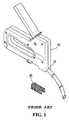
- FIG. 3is a perspective view of a conventional stapling device for outdoor use.
- FIG. 4shows schematically the side view (FIG. 4A) and front view (FIG. 4B) of the conventional stapling device for outdoor use.
- FIG. 5is a schematic view of the wire-pressing element of the present invention, illustrating the type of the wire-pressing element and the relative position thereof.
- FIG. 6Ais an elevation view of the wire-pressing element in accordance with the present invention.
- FIG. 6Bis a front view of the wire-pressing element in accordance with the present invention.
- FIG. 7is a schematic view of another preferred embodiment in accordance with the present invention.
- FIG. 8is a schematic view illustrating the application of the wire-pressing element of another preferred embodiment of the present invention.
- FIG. 9is a perspective view of the wire-pressing element in accordance with the present invention.
- FIG. 10is a schematic view illustrating the application of the wire-pressing element of another preferred embodiment of the present invention.
- the wire-pressing elementis made as one unit from a plastic material and is denoted as reference number 50 .
- the center of the wire-pressing element 50is provided with a wire-pressing section 51 (the wire-pressing section is of any shape, and the shape of the wire-pressing section in the present invention is a rectangular shape).
- the bottom face of the wire-pressing section 51is an arch-shaped slot 52 having an opening facing downward.
- the shape of the slotcan be semi-hemisphere or other shape. In the present invention, a semi-hemisphere is employed.
- the slot 52is used for the pressing of the wire and the two sides of the wire-pressing section 51 are respectively formed into corresponding nailing holes 53 .
- the nailing holes 53 at the front lateral edge of the wire-pressing element 50 corresponding to the front side edge of the stapling device body 10is appropriately corresponding to the staple impaction plate 14 (as shown in FIG. 6A) such that the staple row 20 within the stapling device body 10 is inserted into the nailing holes 53 of the wire-pressing element 50 and into the ground to secure the wire (as shown in FIG. 6 B), thereby the stapling device has a convenient structure with detachable wire-pressing element.
- the wire-pressing element 50in operation, as shown in FIG. 6 A and FIG. 5B, when the wire is to be mounted indoor, the user directly places the staple row 20 into the stapling device body 10 of the stapling device, and the staple-impacting plate 14 urges the staple row 20 on the slot seat 11 to secure the wire.
- the wire-pressing element 50is located at the bottom face of the stapling device.
- the wire-pressing element 50is in aligned with the front edge of the stapling device.
- the nailing holes 53are in alignment with the position of the staple-impacting plate 14 (as shown in FIG. 6 A).
- the staple row 20When the staple-impacting plate 14 knocks onto the staple row 20 , the staple row 20 is forced into the nailing holes 53 and the staple row 20 is inserted onto the mounting object at the bottom face (as shown in FIG. 6 B), so as to secure the wire.
- the usercan use the same stapling device to complete mounting of wire indoor and outdoor, and the operability of the stapling device is convenient.
- FIG. 7there is shown another preferred embodiment of the detachable insulation wire-pressing element of a stapling device, wherein the center of the wire-pressing element 60 is provided with an arch-shaped wire-pressing section 61 having a bottom face being a wire slot 62 with a facing downward opening for mounting wire.
- the center of the wire-pressing section 61is provided with a wire slot 62 , and the two sides of the wire-pressing section 61 are provided with nailing holes 63 .
- the bottom face of the stapling device body 70 corresponding to the front section of the staple-impacting plate 74is formed into a position protrusion 75 .
- the width of the nailing hole 63is slight wider than that of the protrusion with the staple-impacting plate 74 such that the wire-pressing body can engage with the bottom face of the stapling device. This will facilitate the positioning of the wire-pressing body 60 and the staple row 20 can be mounted.
- the insulation body 80 of the wire-pressing bodyis formed into a wire-pressing section 81 having a bottom face being provided with a wire slot 82 .
- the two sides of the wire-pressing section 81are provided with nailing holes 83 .
- the top face of the body 80at the front edge of the nailing hole 83 , is protruded with engaging block 85 .
- the bottom face of the stapling device body 90 corresponding to the front of the staple-impacting plate 94is provided with a position recess 95 , and the recess 95 is adaptable to the engaging block 85 of the wire-pressing body such that the wire-pressing body can be engaged with the bottom face of the stapling device so as to facilitate the mounting of the wire-pressing body 80 .
- the stapling deviceis widely applicable. As the wire-pressing element and the rows of staples are detachable and the nailing holes of wire-pressing element are specially designed the holes can directly align with the staple-impacting plate of the stapling device such that the rows of the staples can be smoothly inserted. As a result, the stapling device can be utilized to mount outdoor wires. Thus stapling device can be utilized to mount wire indoor. Thus, the same stapling device can be used for both indoor and outdoor.
Landscapes
- Engineering & Computer Science (AREA)
- Mechanical Engineering (AREA)
- Dovetailed Work, And Nailing Machines And Stapling Machines For Wood (AREA)
- Portable Nailing Machines And Staplers (AREA)
Abstract
Description
(a) Field of the Invention
The present invention relates to a detachable insulation wire-pressing element of a stapling device, and in particular, to a wire-pressing element having a wire-pressing section and nailing holes allowing a stapling device to secure wires or the like at indoors or outdoors.
(b) Description of the Prior Art
As shown in FIGS. 1 and 2, there is shown a conventional stapling device for mounting wires of an article (electrical appliance) which utilizes a “II”shaped staple row 20. The stapling device has abody 10 having a “u”shaped slot seat 11. The two sides of theslot seat 11 are correspondingly formed with astaple slot 12 for the sliding of the “II”shaped staple row 20. The pushingseat 13 at the rear portion of thebody 10 pushes forward thestaple row 20, and the front end of the interior of thebody 10 is provided with a staple-impactingplate 14 to force out a staple from thestaple row 20. The bottom face of thebody 10 has an arch-shapedwire slot seat 15 for the positioning of wire so that thestaple row 20 can be forced out and smoothly secures the wire.
The above mounting utilizing thestaple row 20 of wire at outdoors may be damaged by weather factors or other factors. The metal within the wire may come into contact with thestaple row 20. As no insulation is provided to thestaple row 20, electrocution may occur. As a result, this type ofstaple row 20 is not used at outdoors.
As shown in FIGS. 3 and 4, in order to overcome the drawback of thestaple row 20, a wire-pressingseat 40 havingstaple body 45 has developed. This wire-pressingseat 40 is only utilized with the staple for outdoor. The bottom face of the interior of the body of the stapling device is provided with a “u”-shaped slot seat 31 and the wire-pressingseat 40 is located within theslot seat 31, and is urged by the pushingseat 33 at the rear of theslot seat 31. The staple-impactingplate 34 knocks onto thestaple body 45 and the wire-pressingseat 40 is forced out, one by one, to secure the wire within thewire slot seat 35.
The conventional wire-pressingseat 40 has solved the drawback of electrocution, however, the large volume wire-pressingseat 40 has to be mounted within theslot seat 31 of the stapling device as the capacity of theslot seat 31 is limited, the user has to continuously re-fill the wire-pressingseat 40. Thus, it is inconvenient in actual operation.
At the same time, thestaple body 45 on the wire-pressingseat 40 has to be one by one, inserted onto the wire-pressingseat 40 in the process of manufacturing, the speed of manufacturing is slow and the cost of manufacturing is high.
In view of the above, the indoor use and outdoor use stapling devices pose individual drawbacks, and the slots seats are different from each other. Therefore, they cannot be used for both devices. In operation, the user needs to bring along with two stapling devices to conform to the requirements. Therefore, it is a troublesome for the user in operating the stapling device. Accordingly, it is an object of the present invention to provide a detachable insulation wire-pressing element of a stapling device, which can mitigate the above drawbacks.
Accordingly, it is an object of the present invention to provide a detachable insulation wire-pressing element of a stapling device, wherein the wire-pressing element is detachable from the stapling device, thereby the stapling device can be used at outdoors and indoors.
Yet another object of the present invention to provide a detachable insulation wire-pressing element of a stapling device, wherein the wire-pressing element has a wire-pressing section at the center of the element and the bottom face of the wire-pressing section is provided with a wire slot having an opening facing downward, the two sides of the wire-pressing section are respectively provided with a corresponding nailing hole, and the nailing hole is corresponding to a staple-impacting plate of the stapling device, thereby a wire-pressing element is formed. The stapling device can be used indoors and outdoors and provides convenient operation and the economic effectiveness of the stapling device is improved.
Other object and advantages of the present invention will become more apparent from the following description taken in conjunction with the accompanying drawing.
FIG. 1 is a perspective view of a conventional stapling device for indoor use.
FIG. 2 shows schematically the side view (FIG. 2A) and front view (FIG. 2B) of the conventional stapling device for indoor use.
FIG. 3 is a perspective view of a conventional stapling device for outdoor use.
FIG. 4 shows schematically the side view (FIG. 4A) and front view (FIG. 4B) of the conventional stapling device for outdoor use.
FIG. 5 is a schematic view of the wire-pressing element of the present invention, illustrating the type of the wire-pressing element and the relative position thereof.
FIG. 6A is an elevation view of the wire-pressing element in accordance with the present invention.
FIG. 6B is a front view of the wire-pressing element in accordance with the present invention.
FIG. 7 is a schematic view of another preferred embodiment in accordance with the present invention.
FIG. 8 is a schematic view illustrating the application of the wire-pressing element of another preferred embodiment of the present invention.
FIG. 9 is a perspective view of the wire-pressing element in accordance with the present invention.
FIG. 10 is a schematic view illustrating the application of the wire-pressing element of another preferred embodiment of the present invention.
Referring to FIG. 5, the wire-pressing element is made as one unit from a plastic material and is denoted asreference number 50. The center of the wire-pressingelement 50 is provided with a wire-pressing section51 (the wire-pressing section is of any shape, and the shape of the wire-pressing section in the present invention is a rectangular shape). The bottom face of the wire-pressingsection 51 is an arch-shaped slot 52 having an opening facing downward. The shape of the slot can be semi-hemisphere or other shape. In the present invention, a semi-hemisphere is employed. Theslot 52 is used for the pressing of the wire and the two sides of the wire-pressingsection 51 are respectively formed intocorresponding nailing holes 53. Thenailing holes 53 at the front lateral edge of the wire-pressing element 50 corresponding to the front side edge of thestapling device body 10 is appropriately corresponding to the staple impaction plate14 (as shown in FIG. 6A) such that thestaple row 20 within thestapling device body 10 is inserted into thenailing holes 53 of the wire-pressingelement 50 and into the ground to secure the wire (as shown in FIG.6B), thereby the stapling device has a convenient structure with detachable wire-pressing element.
In accordance with the above special design of the wire-pressing element, in operation, as shown in FIG.6A and FIG. 5B, when the wire is to be mounted indoor, the user directly places thestaple row 20 into thestapling device body 10 of the stapling device, and the staple-impactingplate 14 urges thestaple row 20 on theslot seat 11 to secure the wire. When the wire is to be mounted outdoor, the user utilizes the same stapling device and the wire-pressingelement 50 is located at the bottom face of the stapling device. The wire-pressingelement 50 is in aligned with the front edge of the stapling device. Thus, thenailing holes 53 are in alignment with the position of the staple-impacting plate14 (as shown in FIG.6A). When the staple-impactingplate 14 knocks onto thestaple row 20, thestaple row 20 is forced into the nailing holes53 and thestaple row 20 is inserted onto the mounting object at the bottom face (as shown in FIG.6B), so as to secure the wire. Thus, the user can use the same stapling device to complete mounting of wire indoor and outdoor, and the operability of the stapling device is convenient.
As shown in FIG. 7, there is shown another preferred embodiment of the detachable insulation wire-pressing element of a stapling device, wherein the center of the wire-pressingelement 60 is provided with an arch-shaped wire-pressingsection 61 having a bottom face being awire slot 62 with a facing downward opening for mounting wire.
As shown in FIG. 8, the center of the wire-pressingsection 61 is provided with awire slot 62, and the two sides of the wire-pressingsection 61 are provided with nailing holes63. The bottom face of thestapling device body 70 corresponding to the front section of the staple-impactingplate 74 is formed into aposition protrusion 75. The width of the nailinghole 63 is slight wider than that of the protrusion with the staple-impactingplate 74 such that the wire-pressing body can engage with the bottom face of the stapling device. This will facilitate the positioning of the wire-pressingbody 60 and thestaple row 20 can be mounted.
Referring to FIGS. 9 and 10, there is shown another preferred embodiment of the present invention. Theinsulation body 80 of the wire-pressing body is formed into a wire-pressingsection 81 having a bottom face being provided with awire slot 82. The two sides of the wire-pressingsection 81 are provided with nailing holes83. Further, the top face of thebody 80, at the front edge of the nailinghole 83, is protruded with engagingblock 85.
The bottom face of thestapling device body 90 corresponding to the front of the staple-impactingplate 94 is provided with aposition recess 95, and therecess 95 is adaptable to the engagingblock 85 of the wire-pressing body such that the wire-pressing body can be engaged with the bottom face of the stapling device so as to facilitate the mounting of the wire-pressingbody 80.
In accordance with the present invention, there are advantages and improvements in effectiveness as follows:
(1) The stapling device is widely applicable. As the wire-pressing element and the rows of staples are detachable and the nailing holes of wire-pressing element are specially designed the holes can directly align with the staple-impacting plate of the stapling device such that the rows of the staples can be smoothly inserted. As a result, the stapling device can be utilized to mount outdoor wires. Thus stapling device can be utilized to mount wire indoor. Thus, the same stapling device can be used for both indoor and outdoor.
(2) Convenient Operation. As the stapling device can be utilized at different environments, the user does not require to carry different stapling device to do the mounting work and besides, no changing of stapling device is required in the course of work.
While the invention has been described with respect to preferred embodiments, it will be clear to those skilled in the art that modifications and improvements may be made to the invention without departing from the spirit and scope of the invention. Therefore, the invention is not to be limited by the specific illustrative embodiment, but only by the scope of the appended claims.
Claims (1)
1. A system comprising of the combination of a detachable insulation wire-pressing element and a stapling device, wherein the wire-pressing element has a wire-pressing section at a center of the element and a bottom face of the wire-pressing section is provided with a wire slot having an opening facing downward, two sides of the wire-pressing section are respectively provided with a corresponding nailing hole, and the nailing hole is corresponding in shape and size to a staple-impacting plate of the stapling device, thereby a wire-pressing element is formed, and wherein on a top face of the wire-pressing element, at a front edge of the nailing hole, is formed a protrusion with an engaging block, and further wherein the stapling device has a bottom face corresponding to a front section of the staple-impacting plate is provided with a position recess corresponding to and inter-fitting with the engaging block.
Priority Applications (2)
| Application Number | Priority Date | Filing Date | Title |
|---|---|---|---|
| US09/934,719US6634537B2 (en) | 2001-08-23 | 2001-08-23 | Detachable insulation wire-pressing element of a stapling device |
| DE20115116UDE20115116U1 (en) | 2001-08-23 | 2001-09-13 | Removable insulating wire press element for staplers |
Applications Claiming Priority (2)
| Application Number | Priority Date | Filing Date | Title |
|---|---|---|---|
| US09/934,719US6634537B2 (en) | 2001-08-23 | 2001-08-23 | Detachable insulation wire-pressing element of a stapling device |
| DE20115116UDE20115116U1 (en) | 2001-08-23 | 2001-09-13 | Removable insulating wire press element for staplers |
Publications (2)
| Publication Number | Publication Date |
|---|---|
| US20030038153A1 US20030038153A1 (en) | 2003-02-27 |
| US6634537B2true US6634537B2 (en) | 2003-10-21 |
Family
ID=26057191
Family Applications (1)
| Application Number | Title | Priority Date | Filing Date |
|---|---|---|---|
| US09/934,719Expired - Fee RelatedUS6634537B2 (en) | 2001-08-23 | 2001-08-23 | Detachable insulation wire-pressing element of a stapling device |
Country Status (2)
| Country | Link |
|---|---|
| US (1) | US6634537B2 (en) |
| DE (1) | DE20115116U1 (en) |
Cited By (65)
| Publication number | Priority date | Publication date | Assignee | Title |
|---|---|---|---|---|
| US20040249391A1 (en)* | 2001-08-09 | 2004-12-09 | Christy Cummins | Surgical stapling device and method |
| US20050109888A1 (en)* | 2003-11-20 | 2005-05-26 | Steven Ryals | Wire protector and retainer |
| US20070039994A1 (en)* | 2005-08-22 | 2007-02-22 | The Stanley Works | Stapler with guide |
| US20070158383A1 (en)* | 2006-01-09 | 2007-07-12 | Li-Jung Cheng | Cable holding assembly for cable stapler |
| US20070210136A1 (en)* | 2004-04-14 | 2007-09-13 | Shinpei Sugihara | Stapler |
| US20090261141A1 (en)* | 2008-04-18 | 2009-10-22 | Stratton Lawrence D | Ergonomic stapler and method for setting staples |
| USD611144S1 (en) | 2006-06-28 | 2010-03-02 | Abbott Laboratories | Apparatus for delivering a closure element |
| US7806910B2 (en) | 2002-11-26 | 2010-10-05 | Abbott Laboratories | Multi-element biased suture clip |
| US7806904B2 (en) | 2000-12-07 | 2010-10-05 | Integrated Vascular Systems, Inc. | Closure device |
| US7819895B2 (en) | 2000-01-05 | 2010-10-26 | Integrated Vascular Systems, Inc. | Vascular sheath with bioabsorbable puncture site closure apparatus and methods of use |
| US7828817B2 (en) | 2000-01-05 | 2010-11-09 | Integrated Vascular Systems, Inc. | Apparatus and methods for delivering a closure device |
| US7841502B2 (en) | 2007-12-18 | 2010-11-30 | Abbott Laboratories | Modular clip applier |
| US7842068B2 (en) | 2000-12-07 | 2010-11-30 | Integrated Vascular Systems, Inc. | Apparatus and methods for providing tactile feedback while delivering a closure device |
| US7850797B2 (en) | 2002-12-31 | 2010-12-14 | Integrated Vascular Systems, Inc. | Methods for manufacturing a clip and clip |
| US7850709B2 (en) | 2002-06-04 | 2010-12-14 | Abbott Vascular Inc. | Blood vessel closure clip and delivery device |
| US7867249B2 (en) | 2003-01-30 | 2011-01-11 | Integrated Vascular Systems, Inc. | Clip applier and methods of use |
| US7879071B2 (en) | 2000-12-07 | 2011-02-01 | Integrated Vascular Systems, Inc. | Closure device and methods for making and using them |
| US7887563B2 (en) | 2001-06-07 | 2011-02-15 | Abbott Vascular Inc. | Surgical staple |
| US7931669B2 (en) | 2000-01-05 | 2011-04-26 | Integrated Vascular Systems, Inc. | Integrated vascular device with puncture site closure component and sealant and methods of use |
| US8007512B2 (en) | 2002-02-21 | 2011-08-30 | Integrated Vascular Systems, Inc. | Plunger apparatus and methods for delivering a closure device |
| US8048108B2 (en) | 2005-08-24 | 2011-11-01 | Abbott Vascular Inc. | Vascular closure methods and apparatuses |
| US8202293B2 (en) | 2003-01-30 | 2012-06-19 | Integrated Vascular Systems, Inc. | Clip applier and methods of use |
| US8202294B2 (en) | 2003-01-30 | 2012-06-19 | Integrated Vascular Systems, Inc. | Clip applier and methods of use |
| US8226681B2 (en) | 2007-06-25 | 2012-07-24 | Abbott Laboratories | Methods, devices, and apparatus for managing access through tissue |
| US8303624B2 (en) | 2010-03-15 | 2012-11-06 | Abbott Cardiovascular Systems, Inc. | Bioabsorbable plug |
| US8313497B2 (en) | 2005-07-01 | 2012-11-20 | Abbott Laboratories | Clip applier and methods of use |
| US8323312B2 (en) | 2008-12-22 | 2012-12-04 | Abbott Laboratories | Closure device |
| US8398676B2 (en) | 2008-10-30 | 2013-03-19 | Abbott Vascular Inc. | Closure device |
| US8398656B2 (en) | 2003-01-30 | 2013-03-19 | Integrated Vascular Systems, Inc. | Clip applier and methods of use |
| US8556930B2 (en) | 2006-06-28 | 2013-10-15 | Abbott Laboratories | Vessel closure device |
| US8556932B2 (en) | 2011-05-19 | 2013-10-15 | Abbott Cardiovascular Systems, Inc. | Collapsible plug for tissue closure |
| US8590760B2 (en) | 2004-05-25 | 2013-11-26 | Abbott Vascular Inc. | Surgical stapler |
| US8603116B2 (en) | 2010-08-04 | 2013-12-10 | Abbott Cardiovascular Systems, Inc. | Closure device with long tines |
| US8617184B2 (en) | 2011-02-15 | 2013-12-31 | Abbott Cardiovascular Systems, Inc. | Vessel closure system |
| US8672953B2 (en) | 2007-12-17 | 2014-03-18 | Abbott Laboratories | Tissue closure system and methods of use |
| US8690910B2 (en) | 2000-12-07 | 2014-04-08 | Integrated Vascular Systems, Inc. | Closure device and methods for making and using them |
| US8757464B2 (en) | 2007-03-01 | 2014-06-24 | Cascade Technologies, Llc | Powered stapling device |
| US8758400B2 (en) | 2000-01-05 | 2014-06-24 | Integrated Vascular Systems, Inc. | Closure system and methods of use |
| US8758399B2 (en) | 2010-08-02 | 2014-06-24 | Abbott Cardiovascular Systems, Inc. | Expandable bioabsorbable plug apparatus and method |
| US8758398B2 (en) | 2006-09-08 | 2014-06-24 | Integrated Vascular Systems, Inc. | Apparatus and method for delivering a closure element |
| US8784447B2 (en) | 2000-09-08 | 2014-07-22 | Abbott Vascular Inc. | Surgical stapler |
| US8808310B2 (en) | 2006-04-20 | 2014-08-19 | Integrated Vascular Systems, Inc. | Resettable clip applier and reset tools |
| US8821534B2 (en) | 2010-12-06 | 2014-09-02 | Integrated Vascular Systems, Inc. | Clip applier having improved hemostasis and methods of use |
| US8858594B2 (en) | 2008-12-22 | 2014-10-14 | Abbott Laboratories | Curved closure device |
| US8893947B2 (en) | 2007-12-17 | 2014-11-25 | Abbott Laboratories | Clip applier and methods of use |
| US8905937B2 (en) | 2009-02-26 | 2014-12-09 | Integrated Vascular Systems, Inc. | Methods and apparatus for locating a surface of a body lumen |
| US8920442B2 (en) | 2005-08-24 | 2014-12-30 | Abbott Vascular Inc. | Vascular opening edge eversion methods and apparatuses |
| US8926633B2 (en) | 2005-06-24 | 2015-01-06 | Abbott Laboratories | Apparatus and method for delivering a closure element |
| US9089311B2 (en) | 2009-01-09 | 2015-07-28 | Abbott Vascular Inc. | Vessel closure devices and methods |
| US9089674B2 (en) | 2000-10-06 | 2015-07-28 | Integrated Vascular Systems, Inc. | Apparatus and methods for positioning a vascular sheath |
| US9149276B2 (en) | 2011-03-21 | 2015-10-06 | Abbott Cardiovascular Systems, Inc. | Clip and deployment apparatus for tissue closure |
| US9173644B2 (en) | 2009-01-09 | 2015-11-03 | Abbott Vascular Inc. | Closure devices, systems, and methods |
| US9282965B2 (en) | 2008-05-16 | 2016-03-15 | Abbott Laboratories | Apparatus and methods for engaging tissue |
| US9314230B2 (en) | 2009-01-09 | 2016-04-19 | Abbott Vascular Inc. | Closure device with rapidly eroding anchor |
| US9332976B2 (en) | 2011-11-30 | 2016-05-10 | Abbott Cardiovascular Systems, Inc. | Tissue closure device |
| US9364209B2 (en) | 2012-12-21 | 2016-06-14 | Abbott Cardiovascular Systems, Inc. | Articulating suturing device |
| US9414820B2 (en) | 2009-01-09 | 2016-08-16 | Abbott Vascular Inc. | Closure devices, systems, and methods |
| US9414824B2 (en) | 2009-01-16 | 2016-08-16 | Abbott Vascular Inc. | Closure devices, systems, and methods |
| US9456811B2 (en) | 2005-08-24 | 2016-10-04 | Abbott Vascular Inc. | Vascular closure methods and apparatuses |
| US9486191B2 (en) | 2009-01-09 | 2016-11-08 | Abbott Vascular, Inc. | Closure devices |
| US9579091B2 (en) | 2000-01-05 | 2017-02-28 | Integrated Vascular Systems, Inc. | Closure system and methods of use |
| US9585647B2 (en) | 2009-08-26 | 2017-03-07 | Abbott Laboratories | Medical device for repairing a fistula |
| US20170157758A1 (en)* | 2014-06-25 | 2017-06-08 | Anthony Richard Howe | Clip dispensing means and clips and storage means therefore |
| US10704583B2 (en) | 2017-09-29 | 2020-07-07 | Black & Decker Inc. | Cable staple assembly and system |
| US11305410B2 (en)* | 2020-08-21 | 2022-04-19 | Pao Shen Enterprises Co., Ltd. | Staple gun |
Families Citing this family (5)
| Publication number | Priority date | Publication date | Assignee | Title |
|---|---|---|---|---|
| GB2515556A (en)* | 2013-06-28 | 2014-12-31 | Anthony Richard Howe | Clip gun-projection position |
| GB2483957B (en)* | 2011-07-20 | 2012-10-24 | Anthony Richard Howe | Cable clip gun |
| GB2492853A (en)* | 2011-10-17 | 2013-01-16 | Anthony Richard Howe | Cable clip gun |
| US10821587B2 (en)* | 2018-03-30 | 2020-11-03 | Black & Decker Inc. | Stapling tool assembly including a wire alignment contact trip |
| US11141849B2 (en)* | 2018-11-19 | 2021-10-12 | Brahma Industries LLC | Protective shield for use with a staple gun |
Citations (7)
| Publication number | Priority date | Publication date | Assignee | Title |
|---|---|---|---|---|
| US662587A (en)* | 1900-05-18 | 1900-11-27 | Charles Chandler Blake | Insulated support for electric conductors. |
| US3085129A (en)* | 1960-08-25 | 1963-04-09 | John M Anderson | Plastic coated metal cable strap or staple |
| US4127250A (en)* | 1977-07-18 | 1978-11-28 | ITW -- Illinois Tool Works | Wire clamping device |
| US4582288A (en)* | 1982-07-16 | 1986-04-15 | Illinois Tool Works Inc. | Cable routing device with cooperating pin and bore |
| US4801061A (en)* | 1985-06-03 | 1989-01-31 | Mangone Peter G Jr | Cable mounting apparatus and method |
| US4805824A (en)* | 1985-10-01 | 1989-02-21 | Erickson Gary W | Apparatus for attaching cable to a surface |
| US5735444A (en)* | 1996-09-23 | 1998-04-07 | Arrow Fastener Co., Inc. | Insulated staple driving system |
- 2001
- 2001-08-23USUS09/934,719patent/US6634537B2/ennot_activeExpired - Fee Related
- 2001-09-13DEDE20115116Upatent/DE20115116U1/ennot_activeExpired - Lifetime
Patent Citations (7)
| Publication number | Priority date | Publication date | Assignee | Title |
|---|---|---|---|---|
| US662587A (en)* | 1900-05-18 | 1900-11-27 | Charles Chandler Blake | Insulated support for electric conductors. |
| US3085129A (en)* | 1960-08-25 | 1963-04-09 | John M Anderson | Plastic coated metal cable strap or staple |
| US4127250A (en)* | 1977-07-18 | 1978-11-28 | ITW -- Illinois Tool Works | Wire clamping device |
| US4582288A (en)* | 1982-07-16 | 1986-04-15 | Illinois Tool Works Inc. | Cable routing device with cooperating pin and bore |
| US4801061A (en)* | 1985-06-03 | 1989-01-31 | Mangone Peter G Jr | Cable mounting apparatus and method |
| US4805824A (en)* | 1985-10-01 | 1989-02-21 | Erickson Gary W | Apparatus for attaching cable to a surface |
| US5735444A (en)* | 1996-09-23 | 1998-04-07 | Arrow Fastener Co., Inc. | Insulated staple driving system |
Cited By (124)
| Publication number | Priority date | Publication date | Assignee | Title |
|---|---|---|---|---|
| US9050087B2 (en) | 2000-01-05 | 2015-06-09 | Integrated Vascular Systems, Inc. | Integrated vascular device with puncture site closure component and sealant and methods of use |
| US7931669B2 (en) | 2000-01-05 | 2011-04-26 | Integrated Vascular Systems, Inc. | Integrated vascular device with puncture site closure component and sealant and methods of use |
| US10111664B2 (en) | 2000-01-05 | 2018-10-30 | Integrated Vascular Systems, Inc. | Closure system and methods of use |
| US7901428B2 (en) | 2000-01-05 | 2011-03-08 | Integrated Vascular Systems, Inc. | Vascular sheath with bioabsorbable puncture site closure apparatus and methods of use |
| US9579091B2 (en) | 2000-01-05 | 2017-02-28 | Integrated Vascular Systems, Inc. | Closure system and methods of use |
| US8758400B2 (en) | 2000-01-05 | 2014-06-24 | Integrated Vascular Systems, Inc. | Closure system and methods of use |
| US7819895B2 (en) | 2000-01-05 | 2010-10-26 | Integrated Vascular Systems, Inc. | Vascular sheath with bioabsorbable puncture site closure apparatus and methods of use |
| US8758396B2 (en) | 2000-01-05 | 2014-06-24 | Integrated Vascular Systems, Inc. | Vascular sheath with bioabsorbable puncture site closure apparatus and methods of use |
| US7828817B2 (en) | 2000-01-05 | 2010-11-09 | Integrated Vascular Systems, Inc. | Apparatus and methods for delivering a closure device |
| US8956388B2 (en) | 2000-01-05 | 2015-02-17 | Integrated Vascular Systems, Inc. | Integrated vascular device with puncture site closure component and sealant |
| US9402625B2 (en) | 2000-09-08 | 2016-08-02 | Abbott Vascular Inc. | Surgical stapler |
| US9060769B2 (en) | 2000-09-08 | 2015-06-23 | Abbott Vascular Inc. | Surgical stapler |
| US8784447B2 (en) | 2000-09-08 | 2014-07-22 | Abbott Vascular Inc. | Surgical stapler |
| US9089674B2 (en) | 2000-10-06 | 2015-07-28 | Integrated Vascular Systems, Inc. | Apparatus and methods for positioning a vascular sheath |
| US9320522B2 (en) | 2000-12-07 | 2016-04-26 | Integrated Vascular Systems, Inc. | Closure device and methods for making and using them |
| US7887555B2 (en) | 2000-12-07 | 2011-02-15 | Integrated Vascular Systems, Inc. | Closure device and methods for making and using them |
| US8128644B2 (en) | 2000-12-07 | 2012-03-06 | Integrated Vascular Systems, Inc. | Closure device and methods for making and using them |
| US7842068B2 (en) | 2000-12-07 | 2010-11-30 | Integrated Vascular Systems, Inc. | Apparatus and methods for providing tactile feedback while delivering a closure device |
| US9554786B2 (en) | 2000-12-07 | 2017-01-31 | Integrated Vascular Systems, Inc. | Closure device and methods for making and using them |
| US8690910B2 (en) | 2000-12-07 | 2014-04-08 | Integrated Vascular Systems, Inc. | Closure device and methods for making and using them |
| US8603136B2 (en) | 2000-12-07 | 2013-12-10 | Integrated Vascular Systems, Inc. | Apparatus and methods for providing tactile feedback while delivering a closure device |
| US8597325B2 (en) | 2000-12-07 | 2013-12-03 | Integrated Vascular Systems, Inc. | Apparatus and methods for providing tactile feedback while delivering a closure device |
| US7879071B2 (en) | 2000-12-07 | 2011-02-01 | Integrated Vascular Systems, Inc. | Closure device and methods for making and using them |
| US7806904B2 (en) | 2000-12-07 | 2010-10-05 | Integrated Vascular Systems, Inc. | Closure device |
| US8486092B2 (en) | 2000-12-07 | 2013-07-16 | Integrated Vascular Systems, Inc. | Closure device and methods for making and using them |
| US9585646B2 (en) | 2000-12-07 | 2017-03-07 | Integrated Vascular Systems, Inc. | Closure device and methods for making and using them |
| US8486108B2 (en) | 2000-12-07 | 2013-07-16 | Integrated Vascular Systems, Inc. | Closure device and methods for making and using them |
| US8257390B2 (en) | 2000-12-07 | 2012-09-04 | Integrated Vascular Systems, Inc. | Closure device and methods for making and using them |
| US10245013B2 (en) | 2000-12-07 | 2019-04-02 | Integrated Vascular Systems, Inc. | Closure device and methods for making and using them |
| US8236026B2 (en) | 2000-12-07 | 2012-08-07 | Integrated Vascular Systems, Inc. | Closure device and methods for making and using them |
| US8182497B2 (en) | 2000-12-07 | 2012-05-22 | Integrated Vascular Systems, Inc. | Closure device |
| US8728119B2 (en) | 2001-06-07 | 2014-05-20 | Abbott Vascular Inc. | Surgical staple |
| US7887563B2 (en) | 2001-06-07 | 2011-02-15 | Abbott Vascular Inc. | Surgical staple |
| US7918873B2 (en) | 2001-06-07 | 2011-04-05 | Abbott Vascular Inc. | Surgical staple |
| US7008435B2 (en)* | 2001-08-09 | 2006-03-07 | Christy Cummins | Surgical stapling device and method |
| US20040249391A1 (en)* | 2001-08-09 | 2004-12-09 | Christy Cummins | Surgical stapling device and method |
| US8007512B2 (en) | 2002-02-21 | 2011-08-30 | Integrated Vascular Systems, Inc. | Plunger apparatus and methods for delivering a closure device |
| US9498196B2 (en) | 2002-02-21 | 2016-11-22 | Integrated Vascular Systems, Inc. | Sheath apparatus and methods for delivering a closure device |
| US8579932B2 (en) | 2002-02-21 | 2013-11-12 | Integrated Vascular Systems, Inc. | Sheath apparatus and methods for delivering a closure device |
| US10201340B2 (en) | 2002-02-21 | 2019-02-12 | Integrated Vascular Systems, Inc. | Sheath apparatus and methods for delivering a closure device |
| US7850709B2 (en) | 2002-06-04 | 2010-12-14 | Abbott Vascular Inc. | Blood vessel closure clip and delivery device |
| US9295469B2 (en) | 2002-06-04 | 2016-03-29 | Abbott Vascular Inc. | Blood vessel closure clip and delivery device |
| US8192459B2 (en) | 2002-06-04 | 2012-06-05 | Abbott Vascular Inc. | Blood vessel closure clip and delivery device |
| US9980728B2 (en) | 2002-06-04 | 2018-05-29 | Abbott Vascular Inc | Blood vessel closure clip and delivery device |
| US8469995B2 (en) | 2002-06-04 | 2013-06-25 | Abbott Vascular Inc. | Blood vessel closure clip and delivery device |
| US7806910B2 (en) | 2002-11-26 | 2010-10-05 | Abbott Laboratories | Multi-element biased suture clip |
| US8202283B2 (en) | 2002-12-31 | 2012-06-19 | Integrated Vascular Systems, Inc. | Methods for manufacturing a clip and clip |
| US8585836B2 (en) | 2002-12-31 | 2013-11-19 | Integrated Vascular Systems, Inc. | Methods for manufacturing a clip and clip |
| US7854810B2 (en) | 2002-12-31 | 2010-12-21 | Integrated Vascular Systems, Inc. | Methods for manufacturing a clip and clip |
| US7850797B2 (en) | 2002-12-31 | 2010-12-14 | Integrated Vascular Systems, Inc. | Methods for manufacturing a clip and clip |
| US10398418B2 (en) | 2003-01-30 | 2019-09-03 | Integrated Vascular Systems, Inc. | Clip applier and methods of use |
| US8926656B2 (en) | 2003-01-30 | 2015-01-06 | Integated Vascular Systems, Inc. | Clip applier and methods of use |
| US8529587B2 (en) | 2003-01-30 | 2013-09-10 | Integrated Vascular Systems, Inc. | Methods of use of a clip applier |
| US7905900B2 (en) | 2003-01-30 | 2011-03-15 | Integrated Vascular Systems, Inc. | Clip applier and methods of use |
| US7867249B2 (en) | 2003-01-30 | 2011-01-11 | Integrated Vascular Systems, Inc. | Clip applier and methods of use |
| US9398914B2 (en) | 2003-01-30 | 2016-07-26 | Integrated Vascular Systems, Inc. | Methods of use of a clip applier |
| US8398656B2 (en) | 2003-01-30 | 2013-03-19 | Integrated Vascular Systems, Inc. | Clip applier and methods of use |
| US9271707B2 (en) | 2003-01-30 | 2016-03-01 | Integrated Vascular Systems, Inc. | Clip applier and methods of use |
| US8202293B2 (en) | 2003-01-30 | 2012-06-19 | Integrated Vascular Systems, Inc. | Clip applier and methods of use |
| US11589856B2 (en) | 2003-01-30 | 2023-02-28 | Integrated Vascular Systems, Inc. | Clip applier and methods of use |
| US8202294B2 (en) | 2003-01-30 | 2012-06-19 | Integrated Vascular Systems, Inc. | Clip applier and methods of use |
| US7118318B2 (en)* | 2003-11-20 | 2006-10-10 | Bellsouth Intellectual Property Corporation | Wire protector and retainer |
| US20050109888A1 (en)* | 2003-11-20 | 2005-05-26 | Steven Ryals | Wire protector and retainer |
| US20070210136A1 (en)* | 2004-04-14 | 2007-09-13 | Shinpei Sugihara | Stapler |
| US7644851B2 (en)* | 2004-04-14 | 2010-01-12 | Max Co., Ltd. | Stapler |
| US8590760B2 (en) | 2004-05-25 | 2013-11-26 | Abbott Vascular Inc. | Surgical stapler |
| US8926633B2 (en) | 2005-06-24 | 2015-01-06 | Abbott Laboratories | Apparatus and method for delivering a closure element |
| US11344304B2 (en) | 2005-07-01 | 2022-05-31 | Abbott Laboratories | Clip applier and methods of use |
| US12070214B2 (en) | 2005-07-01 | 2024-08-27 | Abbott Laboratories | Clip applier and methods of use |
| US9050068B2 (en) | 2005-07-01 | 2015-06-09 | Abbott Laboratories | Clip applier and methods of use |
| US8518057B2 (en) | 2005-07-01 | 2013-08-27 | Abbott Laboratories | Clip applier and methods of use |
| US10085753B2 (en) | 2005-07-01 | 2018-10-02 | Abbott Laboratories | Clip applier and methods of use |
| US8313497B2 (en) | 2005-07-01 | 2012-11-20 | Abbott Laboratories | Clip applier and methods of use |
| US20070039994A1 (en)* | 2005-08-22 | 2007-02-22 | The Stanley Works | Stapler with guide |
| US7562801B2 (en) | 2005-08-22 | 2009-07-21 | The Stanley Works | Stapler with guide |
| US8920442B2 (en) | 2005-08-24 | 2014-12-30 | Abbott Vascular Inc. | Vascular opening edge eversion methods and apparatuses |
| US9456811B2 (en) | 2005-08-24 | 2016-10-04 | Abbott Vascular Inc. | Vascular closure methods and apparatuses |
| US8048108B2 (en) | 2005-08-24 | 2011-11-01 | Abbott Vascular Inc. | Vascular closure methods and apparatuses |
| US7290693B2 (en)* | 2006-01-09 | 2007-11-06 | Li-Jung Cheng | Cable holding assembly for cable stapler |
| US20070158383A1 (en)* | 2006-01-09 | 2007-07-12 | Li-Jung Cheng | Cable holding assembly for cable stapler |
| US8808310B2 (en) | 2006-04-20 | 2014-08-19 | Integrated Vascular Systems, Inc. | Resettable clip applier and reset tools |
| US9962144B2 (en) | 2006-06-28 | 2018-05-08 | Abbott Laboratories | Vessel closure device |
| USD611144S1 (en) | 2006-06-28 | 2010-03-02 | Abbott Laboratories | Apparatus for delivering a closure element |
| US8556930B2 (en) | 2006-06-28 | 2013-10-15 | Abbott Laboratories | Vessel closure device |
| US8758398B2 (en) | 2006-09-08 | 2014-06-24 | Integrated Vascular Systems, Inc. | Apparatus and method for delivering a closure element |
| US8757464B2 (en) | 2007-03-01 | 2014-06-24 | Cascade Technologies, Llc | Powered stapling device |
| US8226681B2 (en) | 2007-06-25 | 2012-07-24 | Abbott Laboratories | Methods, devices, and apparatus for managing access through tissue |
| US8672953B2 (en) | 2007-12-17 | 2014-03-18 | Abbott Laboratories | Tissue closure system and methods of use |
| US8893947B2 (en) | 2007-12-17 | 2014-11-25 | Abbott Laboratories | Clip applier and methods of use |
| US7841502B2 (en) | 2007-12-18 | 2010-11-30 | Abbott Laboratories | Modular clip applier |
| US8820602B2 (en) | 2007-12-18 | 2014-09-02 | Abbott Laboratories | Modular clip applier |
| US20090261141A1 (en)* | 2008-04-18 | 2009-10-22 | Stratton Lawrence D | Ergonomic stapler and method for setting staples |
| US10413295B2 (en) | 2008-05-16 | 2019-09-17 | Abbott Laboratories | Engaging element for engaging tissue |
| US9282965B2 (en) | 2008-05-16 | 2016-03-15 | Abbott Laboratories | Apparatus and methods for engaging tissue |
| US8398676B2 (en) | 2008-10-30 | 2013-03-19 | Abbott Vascular Inc. | Closure device |
| US8657852B2 (en) | 2008-10-30 | 2014-02-25 | Abbott Vascular Inc. | Closure device |
| US9241696B2 (en) | 2008-10-30 | 2016-01-26 | Abbott Vascular Inc. | Closure device |
| US8323312B2 (en) | 2008-12-22 | 2012-12-04 | Abbott Laboratories | Closure device |
| US8858594B2 (en) | 2008-12-22 | 2014-10-14 | Abbott Laboratories | Curved closure device |
| US11439378B2 (en) | 2009-01-09 | 2022-09-13 | Abbott Cardiovascular Systems, Inc. | Closure devices and methods |
| US9486191B2 (en) | 2009-01-09 | 2016-11-08 | Abbott Vascular, Inc. | Closure devices |
| US9173644B2 (en) | 2009-01-09 | 2015-11-03 | Abbott Vascular Inc. | Closure devices, systems, and methods |
| US9089311B2 (en) | 2009-01-09 | 2015-07-28 | Abbott Vascular Inc. | Vessel closure devices and methods |
| US9414820B2 (en) | 2009-01-09 | 2016-08-16 | Abbott Vascular Inc. | Closure devices, systems, and methods |
| US10537313B2 (en) | 2009-01-09 | 2020-01-21 | Abbott Vascular, Inc. | Closure devices and methods |
| US9314230B2 (en) | 2009-01-09 | 2016-04-19 | Abbott Vascular Inc. | Closure device with rapidly eroding anchor |
| US12383247B2 (en) | 2009-01-09 | 2025-08-12 | Abbott Vascular, Inc. | Closure devices and methods |
| US9414824B2 (en) | 2009-01-16 | 2016-08-16 | Abbott Vascular Inc. | Closure devices, systems, and methods |
| US8905937B2 (en) | 2009-02-26 | 2014-12-09 | Integrated Vascular Systems, Inc. | Methods and apparatus for locating a surface of a body lumen |
| US9585647B2 (en) | 2009-08-26 | 2017-03-07 | Abbott Laboratories | Medical device for repairing a fistula |
| US8303624B2 (en) | 2010-03-15 | 2012-11-06 | Abbott Cardiovascular Systems, Inc. | Bioabsorbable plug |
| US8758399B2 (en) | 2010-08-02 | 2014-06-24 | Abbott Cardiovascular Systems, Inc. | Expandable bioabsorbable plug apparatus and method |
| US8603116B2 (en) | 2010-08-04 | 2013-12-10 | Abbott Cardiovascular Systems, Inc. | Closure device with long tines |
| US8821534B2 (en) | 2010-12-06 | 2014-09-02 | Integrated Vascular Systems, Inc. | Clip applier having improved hemostasis and methods of use |
| US8617184B2 (en) | 2011-02-15 | 2013-12-31 | Abbott Cardiovascular Systems, Inc. | Vessel closure system |
| US9149276B2 (en) | 2011-03-21 | 2015-10-06 | Abbott Cardiovascular Systems, Inc. | Clip and deployment apparatus for tissue closure |
| US8556932B2 (en) | 2011-05-19 | 2013-10-15 | Abbott Cardiovascular Systems, Inc. | Collapsible plug for tissue closure |
| US9332976B2 (en) | 2011-11-30 | 2016-05-10 | Abbott Cardiovascular Systems, Inc. | Tissue closure device |
| US10537312B2 (en) | 2012-12-21 | 2020-01-21 | Abbott Cardiovascular Systems, Inc. | Articulating suturing device |
| US9364209B2 (en) | 2012-12-21 | 2016-06-14 | Abbott Cardiovascular Systems, Inc. | Articulating suturing device |
| US11672518B2 (en) | 2012-12-21 | 2023-06-13 | Abbott Cardiovascular Systems, Inc. | Articulating suturing device |
| US20170157758A1 (en)* | 2014-06-25 | 2017-06-08 | Anthony Richard Howe | Clip dispensing means and clips and storage means therefore |
| US10704583B2 (en) | 2017-09-29 | 2020-07-07 | Black & Decker Inc. | Cable staple assembly and system |
| US11305410B2 (en)* | 2020-08-21 | 2022-04-19 | Pao Shen Enterprises Co., Ltd. | Staple gun |
Also Published As
| Publication number | Publication date |
|---|---|
| DE20115116U1 (en) | 2001-11-22 |
| US20030038153A1 (en) | 2003-02-27 |
Similar Documents
| Publication | Publication Date | Title |
|---|---|---|
| US6634537B2 (en) | Detachable insulation wire-pressing element of a stapling device | |
| US5551883A (en) | Electrical connector | |
| CA1289215C (en) | Connector clip for ribbon cable connector | |
| US5933326A (en) | Clipping device for heat sink | |
| US4803545A (en) | Self-fixturing heat sink | |
| EP3149809B1 (en) | Electrical connector for use with printed circuit boards | |
| EP2200131A1 (en) | Low-profile D-subshell connector system with interlocking components | |
| JPH0346776A (en) | Fixing device for connector | |
| US5064381A (en) | Electric connecting device | |
| US5623124A (en) | Wall switch housing | |
| US20050194176A1 (en) | Faceplate attachment system | |
| US4113337A (en) | Connector constructions and mounting means and hoods therefor | |
| JP2019502247A (en) | LED socket for receiving CoB-LED and base for such LED socket | |
| US6890192B2 (en) | Sequential connection-type connector and additional contact used in the same | |
| US4043452A (en) | C-ring holder | |
| US20060128229A1 (en) | Battery connector | |
| US4127924A (en) | Method of assembling electrical connectors | |
| US6628514B2 (en) | Fastener for securing a data storage device to a bracket | |
| US7104162B1 (en) | Device for unfastening pipe fasteners | |
| US2723382A (en) | Current tap for attachment to the end of an extension cord | |
| US7604495B2 (en) | Zero insertion force connector with improved driving device | |
| EP0506263B1 (en) | Connector | |
| GB2251738A (en) | Electrical connector and an electrical contact element | |
| JPS6015253Y2 (en) | Grounding terminal board for electrical equipment | |
| US11444395B1 (en) | Terminal block with integral guiding structure |
Legal Events
| Date | Code | Title | Description |
|---|---|---|---|
| FEPP | Fee payment procedure | Free format text:PAT HOLDER CLAIMS SMALL ENTITY STATUS, ENTITY STATUS SET TO SMALL (ORIGINAL EVENT CODE: LTOS); ENTITY STATUS OF PATENT OWNER: SMALL ENTITY | |
| FPAY | Fee payment | Year of fee payment:4 | |
| REMI | Maintenance fee reminder mailed | ||
| LAPS | Lapse for failure to pay maintenance fees | ||
| STCH | Information on status: patent discontinuation | Free format text:PATENT EXPIRED DUE TO NONPAYMENT OF MAINTENANCE FEES UNDER 37 CFR 1.362 | |
| FP | Lapsed due to failure to pay maintenance fee | Effective date:20111021 |