US6634244B2 - Methods for collecting fluid samples having select concentrations of particles - Google Patents
Methods for collecting fluid samples having select concentrations of particlesDownload PDFInfo
- Publication number
- US6634244B2 US6634244B2US10/012,874US1287401AUS6634244B2US 6634244 B2US6634244 B2US 6634244B2US 1287401 AUS1287401 AUS 1287401AUS 6634244 B2US6634244 B2US 6634244B2
- Authority
- US
- United States
- Prior art keywords
- filter
- fluid
- particles
- collection
- collected
- Prior art date
- Legal status (The legal status is an assumption and is not a legal conclusion. Google has not performed a legal analysis and makes no representation as to the accuracy of the status listed.)
- Expired - Lifetime
Links
Images


Classifications
- G—PHYSICS
- G01—MEASURING; TESTING
- G01N—INVESTIGATING OR ANALYSING MATERIALS BY DETERMINING THEIR CHEMICAL OR PHYSICAL PROPERTIES
- G01N15/00—Investigating characteristics of particles; Investigating permeability, pore-volume or surface-area of porous materials
- G01N15/06—Investigating concentration of particle suspensions
- G01N15/0606—Investigating concentration of particle suspensions by collecting particles on a support
- G01N15/0618—Investigating concentration of particle suspensions by collecting particles on a support of the filter type
- G—PHYSICS
- G01—MEASURING; TESTING
- G01N—INVESTIGATING OR ANALYSING MATERIALS BY DETERMINING THEIR CHEMICAL OR PHYSICAL PROPERTIES
- G01N1/00—Sampling; Preparing specimens for investigation
- G01N1/28—Preparing specimens for investigation including physical details of (bio-)chemical methods covered elsewhere, e.g. G01N33/50, C12Q
- G01N1/40—Concentrating samples
- G—PHYSICS
- G01—MEASURING; TESTING
- G01N—INVESTIGATING OR ANALYSING MATERIALS BY DETERMINING THEIR CHEMICAL OR PHYSICAL PROPERTIES
- G01N1/00—Sampling; Preparing specimens for investigation
- G01N1/28—Preparing specimens for investigation including physical details of (bio-)chemical methods covered elsewhere, e.g. G01N33/50, C12Q
- G01N1/2813—Producing thin layers of samples on a substrate, e.g. smearing, spinning-on
- G—PHYSICS
- G01—MEASURING; TESTING
- G01N—INVESTIGATING OR ANALYSING MATERIALS BY DETERMINING THEIR CHEMICAL OR PHYSICAL PROPERTIES
- G01N1/00—Sampling; Preparing specimens for investigation
- G01N1/28—Preparing specimens for investigation including physical details of (bio-)chemical methods covered elsewhere, e.g. G01N33/50, C12Q
- G01N1/40—Concentrating samples
- G01N1/4077—Concentrating samples by other techniques involving separation of suspended solids
- Y—GENERAL TAGGING OF NEW TECHNOLOGICAL DEVELOPMENTS; GENERAL TAGGING OF CROSS-SECTIONAL TECHNOLOGIES SPANNING OVER SEVERAL SECTIONS OF THE IPC; TECHNICAL SUBJECTS COVERED BY FORMER USPC CROSS-REFERENCE ART COLLECTIONS [XRACs] AND DIGESTS
- Y10—TECHNICAL SUBJECTS COVERED BY FORMER USPC
- Y10T—TECHNICAL SUBJECTS COVERED BY FORMER US CLASSIFICATION
- Y10T436/00—Chemistry: analytical and immunological testing
- Y10T436/10—Composition for standardization, calibration, simulation, stabilization, preparation or preservation; processes of use in preparation for chemical testing
- Y10T436/107497—Preparation composition [e.g., lysing or precipitation, etc.]
- Y—GENERAL TAGGING OF NEW TECHNOLOGICAL DEVELOPMENTS; GENERAL TAGGING OF CROSS-SECTIONAL TECHNOLOGIES SPANNING OVER SEVERAL SECTIONS OF THE IPC; TECHNICAL SUBJECTS COVERED BY FORMER USPC CROSS-REFERENCE ART COLLECTIONS [XRACs] AND DIGESTS
- Y10—TECHNICAL SUBJECTS COVERED BY FORMER USPC
- Y10T—TECHNICAL SUBJECTS COVERED BY FORMER US CLASSIFICATION
- Y10T436/00—Chemistry: analytical and immunological testing
- Y10T436/25—Chemistry: analytical and immunological testing including sample preparation
- Y10T436/25375—Liberation or purification of sample or separation of material from a sample [e.g., filtering, centrifuging, etc.]
Definitions
- the inventiongenerally relates to laboratory instruments and processes for collecting samples and, more particularly, to laboratory instruments and processes to generate fluid samples that have known concentrations of a targeted particulate material.
- the isolation stepis performed as a preliminary step to further testing that centers around the characteristics of the isolated component.
- a centrifugeto separate composite materials into the individual elements.
- a lab techniciancan place the composite material into a test-tube-like container. The lab technician inserts the container into the centrifuge and activates the centrifuge for sufficient time to separate out the element or elements of interest. Upon completion of a centrifugal separation, the lab technician removes the container and extracts from the stratified sample the element or elements.
- centrifugal separationcan work well, it is typically labor-intensive and often poorly suited for isolating small particulate matter, such as cellular material. Moreover, the centrifugal technique fails to provide a separation process that readily yields samples with known concentrations of a targeted element.
- Instruments and processes according to the inventionprovide for the preparation of a fluid sample that has a substantially known concentration of a select particulate matter.
- the inventionis understood as laboratory instruments for sample preparation. These instruments can include a filter that is submersible within a fluid suspension of particulate matter. To collect particulate matter from the fluid suspension, the instruments can cause a fluid flow that pulls fluid across the filter to trap particulate matter against one surface of the filter. The instruments can then remove the filter from the fluid suspension and dispose the filter above a collection vessel such that the side of the filter that is carrying particulate matter is positioned above the opening of the collection vessel.
- the laboratory instrumentscan then send a collection fluid through the filter in a direction opposite to the original fluid flow, thereby washing the particulate matter off the filter and into the collection vessel.
- the laboratory instruments according to the inventioncan provide samples having a known concentration by passing a known volume of collection fluid through the filter, thereby trapping the collected particulate matter within a known volume of collection fluid.
- the inventionis understood as methods for reproducibly generating a fluid sample having a select concentration of particles.
- Methods of the inventioncan include the steps of providing a fluid suspension of dispersed particles, disposing a filter having a first side and a second side within the fluid suspension and flowing the fluid suspension across the filter from the first side to the second side, such that a substantially known quantity of particles collect onto the first side of the filter, removing the filter and the particles collected thereon from the fluid suspension, and passing a known volume of collection fluid through the filter to remove substantially the particles collected on the first side, and to collect the particles within the known volume of collection fluid.
- the processes according to the inventioncan include a step of disposing a filter that includes providing a particle collection device having an intake port and an evacuation port, and having the filter spanning the intake port. Further practices according to the invention can include a step of generating a fluid flow by evacuating the particle collection device to draw fluid across the filter and through the intake port and into the collection device.
- these processescan include a step of passing a known quantity of collection fluid through the filter by applying a select fluid pressure within the collection device to force fluid collected therein back across the filter. Further, when passing a known volume of collection fluid through the filter, the processes of the invention can include the step of disposing the filter collection device at a select angle to generate thereby a drip of collection fluid that has the particles collected therein.
- the inventioncan include the steps of selecting a filter that has a pore size adapted, dimensionally, for collecting particles of a pre-determined size.
- filterscan include cellulose, polyester, polycarbonate, nylon and teflon filters, and can have pore sizes suited for collecting a target material.
- filter pore sizestypically range between 0.2 and 20 microns.
- the processes according to the inventioncan also include further steps for analyzing the particles and fluid samples that are collected.
- the processes of the inventioncan include the further steps of lysing the collected particles, or providing a portion of the collected particles in the known volume of collection fluid as a sample for diagnostic assay.
- the processes according to the inventioncan include the steps of causing a flow of fluid and measuring a characteristic representative of the quantity of particles collected against the filter. Moreover, the processes can interrupt the step of flowing the fluid suspension in response to a measured characteristic that represents a preselected quantity of particles. Accordingly, processes according to the invention can monitor characteristics of the fluid flow to determine when a preselected quantity of particles have collected against the filter.
- processes according to the inventioncan direct the fluid suspension across the filter by applying a known pressure to the fluid suspension. Further these processes can apply pressure to the fluid suspension as a succession of know pressures. In this practice, the processes can measure a characteristic representative of the rate of change of pressure and can determine from this measured characteristic a quantity of particles collected against the filter surface.
- the inventionprovides processes that can be employed for incrementally achieving a desired concentration of particles within a known volume of fluid.
- the processes of the inventioncan be iterative in that upon collecting a first sample of collected particles within a known volume of fluid, this fluid sample can be again processed according to the invention to provide a fluid sample having an alternative concentration of particles.
- the inventionprovides apparatus for reproducibly collecting a sample having a select concentration.
- Such apparatuscan comprise a filter having a first side and a second side and being submersible within a fluid that contains a quantity of particles, an element for flowing the fluid across the filter in a direction that travels from the first side to the second side such that a substantially known quantity of particles collects onto the first side of the filter, an element for removing the filter and the particles collected thereon from the fluid suspension, and an element for passing a known volume of collection fluid through the filter to remove substantially the particles collected on the first side and to collect the particles within a known volume of collection fluid.
- the inventionoffers significant advantages over known methods for collecting fluid samples by providing systems and methods that generate fluid samples of particulate material in select concentrations. Moreover, the invention further provides automated laboratory instrumentation that can perform each step of the fluid sample preparation process such that the systems automatically and reproducibly provide fluid samples each having select and known concentrations.
- FIG. 1illustrates in functional block diagram form one system according to the invention for providing a fluid sample having a select concentration.
- FIG. 2illustrates the system of FIG. 1 in operation for collecting cells from a fluid suspension.
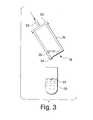
- FIG. 3illustrates the system of FIG. 1 in operation for collecting particles within a known volume of collection fluid.
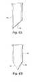
- FIGS. 4 a and 4 billustrate alternative embodiments of collection vessels suitable for practice with the system depicted in FIG. 1 .
- FIGS. 5 a and 5 bdiagramatically illustrate known pressures suitable for drawing fluid across the filter depicted in FIG. 1 .
- FIGS. 6 and 7illustrate an alternative embodiment of the invention.
- FIG. 1depicts the functional elements of one embodiment of the invention. More particularly, FIG. 1 depicts a system 10 that includes a container 12 , a fluid suspension of dispersed particles 14 , a particle collection device 16 , a filter 18 , a cap 20 , an actuator 21 , a conduit 22 , a pneumatic source 24 , and a processor 28 .
- the container 12holds the fluid sample 14 , and makes it available for sampling by the collection device 16 .
- the system 10uses a pneumatic particle collection technique wherein the system 10 employs pneumatic action provided by the pneumatic source 24 to draw a portion of the fluid sample 14 past the filter 18 and into the collection device 16 . Particles dispersed within the fluid sample 14 collect onto one side of the filter 18 and can be removed from the fluid sample 14 by extraction of the particle collection device 16 .
- the processor 28determines a measure representative of the quantity of particles that have collected against the filter 18 . Accordingly, upon extraction of the collection device 16 from the sample 14 , the system 10 has collected a substantially known quantity of particles from the fluid sample 14 .
- the container 12can be any container suitable for holding a fluid material and for providing access to the fluid material by a particle collection device, such as the device 16 .
- a particle collection devicesuch as the device 16 .
- the container 12is commonly a sterilized plastic container suited for holding a biological sample and for disposal after the fluid sample 14 is processed by the system 10 .
- the fluid sample 14 depicted in FIG. 1is a liquid sample that has dispersed therein a quantity of particles.
- the quantity of particlesis relatively unknown and, therefore, the concentration of particles within the sample volume is also unknown.
- the particles within a fluid sample 14are dispersed such that there exists, within the sample, some population of particles that are separate from, and independent of, any of the other particles. These disperse independent particles are well-suited for collection by the filter 18 as a portion of the fluid sample 14 is drawn across the filter 18 and into the collection device 16 . Accordingly, in one practice of the invention, the system 10 disperses cells within the fluid sample 14 by actuating the particle collection device 16 .
- the system 10rapidly rotates the particle collection device 16 to agitate the fluid sample 14 and break-up clumps of particles that may exist within the fluid sample.
- the actuation of the collection device 16can break-up clumped cells, such that there exists within the fluid sample 14 a population of individual cells, and a reduced population of clumped cells.
- the system 10collects a known quantity of cells from a biological fluid sample 14 .
- the fluid sample 14can be comprised of an aqueous preservation solution that contains a biological sample, such as tissue cells, blood cells, scrapings, aspirates, or other such biological materials and samples.
- the particle collection device 16 depicted in FIG. 1has a cylindrical sidewall, which is shown in cross section, that provides a rim for supporting the filter 18 that attaches at one end of device 16 .
- a cap 20spans across the device 16 to fluidically seal the interior chamber of device 16 .
- the cap 20has an aperture that receives the fluid conduit 22 that fluidically couples the interior of device 16 with the pneumatic source 24 .
- the sidewall of the particle collection device 16can be a plastic material, such as polystyrene, that provides at one end, a rim suitable for attaching the filter 18 .
- the filter 18can be a polycarbonate membrane having a porosity selected for collecting particles of a particular size from the fluid sample 14 .
- One such filter 18is a polycarbonate membrane marketed by the Nuclepore Corporation in Pleasanton, Calif.
- Other filterscan be formed from materials including cellulose, nylon, polyester, teflon, or any other suitable material.
- the filter membranecan have a pore size or sizes suitable for collecting cells of particular sizes and can be, for example, pores of size approximately 0.2 to 20 microns.
- the depicted particle collection device 16can be a filter cylinder device manufactured and marketed by the Cytyc Corporation of Boxboro, Mass., the assignee hereof. However, the pore size is to be selected as a function of the target material being collected.
- FIG. 1includes pneumatic system for evacuating fluid, typically air, from the interior of the device to draw a portion of the fluid sample 14 across the filter 18 .
- the pneumatic systemincludes the source 24 and the conduit 22 .
- the conduit 22extends through the aperture of the cap 20 and replaces the interior of the particle collection device 16 in fluid communication with the pneumatic source 24 .
- the pneumatic source 24can be a vacuum source that evacuates the interior of the particle collection device 16 , thereby creating a pressure differential across the filter 18 , causing a portion of the fluid sample to cross the filter 18 .
- the pneumatic source 24can be any pneumatic source suitable for evacuating, or partially evacuating, the interior of the particle device 16 and thereby creating a pressure differential across the filter 18 that acts as negative pressure on the fluid sample 14 .
- the system 10includes a sensor 26 that couples to the conduit 22 and that couples, via a transmission path, to the processor 28 .
- the sensor 26is a pressure sensor that measures the pressure being applied by the pneumatic source 24 to the interior of the collection device 16 .
- the sensor 26acts as a transducer to generate an electrical signal representative of this pressure.
- the processor 28receives the signal generated by the transducer sensor 26 and generates, responsive to this signal, a quantity signal representative of the quantity of particles that have collected against the surface of the filter 18 .
- the sensor 26in this embodiment of the invention, can be any sensor suitable for generating a signal representative of the pressure within the interior of the particle collection device 16 .
- the processor 28 depicted in FIG. 1can be any data processing system having an input interface for receiving a signal generated by a sensor element and capable of processing that signal to generate a quantity signal representative substantially of the number of particles that have collected against the filter 18 .
- FIG. 2depicts the system of FIG. 1 having drawn a portion of the sample fluid 14 across the filter 18 and into the interior of the collection device 16 .
- the pneumatic source 24creates a negative pressure within the interior of the collection device 16 that generates a flow of the fluid sample 14 across the filter 18 .
- Drawing a fluid sample 14 across the filter 18causes the particles dispersed within the fluid sample 14 to collect against the filter 18 and, in particular, to block the pores of the filter membrane.
- the action of blocking the pores of the filter membrane 18is understood to decrease effectively the porosity of the filter membrane.
- the amount of time it takes for the negative pressure to return to equilibrium after the pneumatic source has changed the interior pressure within the collection device 16is dependent, in part, on the number of pores of filter 18 available for passing fluid into the interior of the device 16 . Consequently, as particles collect against the filter surface 18 , the pores of the filter 18 are sealed, thereby reducing the number of pores available for passing fluid to the interior of the device 16 .
- the reduction of available porescan increase the amount of time it takes for the vacuum inside the collection device to return to equilibrium. Further, the rate of pressure change within device 16 changes as pores are blocked.
- the pressure change and rate of pressure change within the device 16can be representative of the number of particles that have collected against the surface of the filter 18 .
- the processor 28can track the pressure within device 16 and determine, responsive thereto, a number representative of a quantity of particles collected against the filter 18 .
- the system 10creates a flow of fluid to the filter 18 until the processor 28 determines, from measures of the pressure within the device 16 , that substantially each pore of filter 28 is blocked by a collected particle. For each filter 18 , the number of pores is approximately known. Therefore, the processor 28 can generate a quantity signal representative of substantially the number of particles it takes to block each pore of the filter 18 .
- the processor 28can determine from measures of the rate of pressure change within the device 16 , quantity signals representative of the number of particles that have collected against the filter 18 to partially block the filter. Accordingly, in this embodiment, the system 10 can collect a known quantity of particles from a fluid sample 14 that has a population of particles dispersed therein which would be insufficient to completely obstruct the flow of fluid to the interior of the device 16 .
- the system 10 depicted in FIGS. 1 and 2can be employed to determine the concentration of the dispersed particles within the fluid sample 14 .
- the system 10draws a known volume of fluid across the filter 18 .
- the system 10can determine the concentration of the fluid sample 14 responsive to the quantity of particles collected out of the known volume of fluid drawn across the filter 18 .
- the pneumatic source 24can draw a portion of the fluid sample 14 to the filter 18 and into the cylinder 16 .
- the processor 28can employ this known volume and a measure of the particles collected against filter 18 to measure the concentration of the fluid sample 14 .
- the entire volume of the fluid sample 14can be flowed across the filter 18 to collect and count the particles within the fluid suspension.
- the system 10can continuously filter a portion of the fluid sample 14 until the entire fluid sample 14 has been substantially processed by the system 10 .
- a plurality of filterscan be sequentially disposed within the sample 14 , employing a new filter each time a portion of the fluid sample 14 is processed.
- a process according to the inventioncan include a further step of rinsing the filter membrane after each time the filter processes a portion of the fluid sample 14 .
- the rinsing processcan include a step of disposing the filter 18 within a fluid bath and actuating the filter therein to remove particles collected against the membrane.
- the step of rinsing the filter 18can include the step of placing the filter 18 within a fluid bath and applying a positive pressure to the interior of the device 16 to effectively blow any particles collected onto the membrane into the cleansing fluid.
- Alternative practices for removing particles collected against the filtercan be practiced with the invention without departing from the scope thereof.
- FIG. 3depicts a further step of the invention and shows the particle collection device 16 disposed above a collection 30 having a preservation fluid 32 contained therein.
- the collection device 16is held at an angle such that a corner portion of a device 16 is disposed directly above the container 30 and the filter 18 is disposed at an angle relative to an axis extending parallel to the sides of the container 30 .
- a known volume of collection fluidis passed through the filter 18 to remove substantially all the particles collected onto the opposite side of the filter 18 and to collect those particles within the known volume of collection fluid.
- the collection fluid 38 depicted in FIG. 3can be, in one practice, the filtrate generated by passing the fluid sample 14 through the filter 18 .
- the collection fluidcan be a preservation fluid passed into the interior of the particle collection device 16 .
- the pneumatic source 24applies, via conduit 22 , a positive pressure within the interior of the collection device 16 to effectively press a portion of the collection fluid 38 through the filter 18 thereby removing the particles from the surface of the filter 18 , and collecting the particles within the fluid 38 .
- a positive pressureis applied to the interior of the particle collection device 16 to pass a volume of collection fluid through the filter 18 to form a drop 34 of collection fluid having gathered therein substantially all the particles previously collected by the filter 18 .
- the drop of collection fluid 34can, with the particles contained therein, pass to the container 30 .
- the processprovides a known volume of preservation fluid 32 within the container 30 . Accordingly, the process provides a fluid sample having a substantially known quantity of particles contained within a substantially known volume of fluid.
- FIGS. 4 a and 4 bdepict alternative embodiments of the collection devices suitable for practice with the present invention.
- FIG. 4 adepicts a collection device 40 that has an edge 42 that extends transverse relative to the sidewalls of the collection device 40 .
- This adjacent edge 42facilitates the development of a drop of collection fluid having particles dissolved therein.
- FIG. 4 bdepicts a further alternative embodiment of the collection device suitable for practice with the invention.
- the collection device 44has a first edge 46 and a second edge 48 , both which extend transverse to the sidewalls of the collection device 44 .
- the opposing transverse edges 46 and 48together facilitate the development of a drop of fluid.
- the filtercan span entirely across one end of the collection device or can span across a portion of that collection device. It will further be understood that other particle collection devices can be practiced with the present invention without departing from the scope thereof.
- FIGS. 5 a and 5 bdepict pressure pulses suitable for drawing fluid across the filter 18 .
- FIG. 5 adepicts a first set of axes including a vertical axis labeled P designating the interior pressure of the collection device 16 .
- FIG. 5 ashows increasing pressure as values increase from P 2 to P 1 .
- FIG. 5 aalso shows a horizontal axis, labeled T. The horizontal axis shows increasing time in the direction from t 0 to t 1 .
- the pneumatic source 24can act as a vacuum to decrease pressure within the device 16 from an initial pressure of P 1 to a subsequent pressure P 2 .
- Pressure within the devicedecreases from P 1 to P 3 during the time interval between t 0 and t 2 .
- the processor 28measures the interior pressure and determines the time interval over which the interior pressure increases from P 90 to P 60 , where P 90 , represents an interior pressure that is approximately 90% of the peak negative pressure P 3 and P 60 represents an interior pressure that is approximately 60% of the peak negative pressure P 3 .
- FIG. 5 adepicts this time interval as occurring between t 3 and t 4 .
- the processor 28employs these time and pressure measurements to determine a rate of pressure change which is representative of the number of collected particles. This can include the processor 28 determining an exponential rate of decay of the interior pressure.
- the processor 28can determine a quantity signal, responsive to the rate of pressure change within the device 16 , and being representative of the number of particles collected against the filter 18 .
- FIG. 5 bdepicts an alternative practice of the invention wherein a plurality of pressure pulses is provided to the interior of the particle collection device 16 .
- the pneumatic source 24employs several pressure pulses to draw a portion of the fluid sample 14 to the filter 18 .
- the plural pulsesare generally provided as a sequence of negative pressure bursts that act like a sequence of sips.
- the processor 28can determine, each time the pneumatic source applies the negative pressure, the rate of pressure change within the collection device 16 . This allows the processor 28 to monitor the quantity of particles collected against the filter 18 .
- the system 10upon detection of sufficient number of particles collected against the filter 18 , the system 10 removes the filter 18 from the fluid sample and, as described with reference to FIG. 3, collects the selected quantity of particles within a known volume of collection fluid.
- FIGS. 6 and 7depict a further alternative embodiment of the invention. More particularly, FIG. 6 depicts a system 50 that includes a volumetric control 51 , a fluid sample source 52 , a collection fluid source 54 , a first pneumatic source 58 , a second pneumatic source 60 , a collection device 62 , having a first chamber 64 and a second chamber 68 , and a filter 70 disposed between the chambers 64 and 68 .
- the fluid sample source 52can contain a fluid sample of dispersed particles. Fluid sample source 52 can provide the fluid suspension of dispersed particles into the collection device 62 via the fluid conduit that couples between sample source 52 and the container section 68 .
- the second pneumatic source 60can apply a negative pressure within the interior of the first chamber 64 to draw a portion of the fluid sample across the filter 70 .
- the second pneumatic source 60evacuates the first chamber 64 of all filtrate leaving first chamber 64 empty.
- the system 50can then activate collection source 54 to provide collection fluid into the first chamber 64 of particle collection device 62 .
- the first peneumatic source 58can draw collection fluid across the filter 70 to collect, within the collection fluid, the quantity of particles collected against the filter 70 .
- the first pneumatic source 58can draw selected amounts of the collection fluid past filter 70 to collect the particles within a known volume of collection fluid.
Landscapes
- Chemical & Material Sciences (AREA)
- Physics & Mathematics (AREA)
- Health & Medical Sciences (AREA)
- Life Sciences & Earth Sciences (AREA)
- Analytical Chemistry (AREA)
- Biochemistry (AREA)
- General Health & Medical Sciences (AREA)
- General Physics & Mathematics (AREA)
- Immunology (AREA)
- Pathology (AREA)
- Dispersion Chemistry (AREA)
- Sampling And Sample Adjustment (AREA)
Abstract
Description
Claims (17)
Priority Applications (2)
| Application Number | Priority Date | Filing Date | Title |
|---|---|---|---|
| US10/012,874US6634244B2 (en) | 1996-11-01 | 2001-11-12 | Methods for collecting fluid samples having select concentrations of particles |
| US10/648,698US20040219073A1 (en) | 1996-11-01 | 2003-08-25 | Systems and methods for generating fluid samples having select concentration of particles |
Applications Claiming Priority (3)
| Application Number | Priority Date | Filing Date | Title |
|---|---|---|---|
| US08/742,647US5942700A (en) | 1996-11-01 | 1996-11-01 | Systems and methods for collecting fluid samples having select concentrations of particles |
| US09/372,146US6318190B1 (en) | 1996-11-01 | 1999-08-20 | Systems for collecting fluid samples having select concentrations of particles |
| US10/012,874US6634244B2 (en) | 1996-11-01 | 2001-11-12 | Methods for collecting fluid samples having select concentrations of particles |
Related Parent Applications (1)
| Application Number | Title | Priority Date | Filing Date |
|---|---|---|---|
| US09/372,146ContinuationUS6318190B1 (en) | 1996-11-01 | 1999-08-20 | Systems for collecting fluid samples having select concentrations of particles |
Related Child Applications (1)
| Application Number | Title | Priority Date | Filing Date |
|---|---|---|---|
| US10/648,698ContinuationUS20040219073A1 (en) | 1996-11-01 | 2003-08-25 | Systems and methods for generating fluid samples having select concentration of particles |
Publications (2)
| Publication Number | Publication Date |
|---|---|
| US20020040610A1 US20020040610A1 (en) | 2002-04-11 |
| US6634244B2true US6634244B2 (en) | 2003-10-21 |
Family
ID=24985683
Family Applications (4)
| Application Number | Title | Priority Date | Filing Date |
|---|---|---|---|
| US08/742,647Expired - LifetimeUS5942700A (en) | 1996-11-01 | 1996-11-01 | Systems and methods for collecting fluid samples having select concentrations of particles |
| US09/372,146Expired - LifetimeUS6318190B1 (en) | 1996-11-01 | 1999-08-20 | Systems for collecting fluid samples having select concentrations of particles |
| US10/012,874Expired - LifetimeUS6634244B2 (en) | 1996-11-01 | 2001-11-12 | Methods for collecting fluid samples having select concentrations of particles |
| US10/648,698AbandonedUS20040219073A1 (en) | 1996-11-01 | 2003-08-25 | Systems and methods for generating fluid samples having select concentration of particles |
Family Applications Before (2)
| Application Number | Title | Priority Date | Filing Date |
|---|---|---|---|
| US08/742,647Expired - LifetimeUS5942700A (en) | 1996-11-01 | 1996-11-01 | Systems and methods for collecting fluid samples having select concentrations of particles |
| US09/372,146Expired - LifetimeUS6318190B1 (en) | 1996-11-01 | 1999-08-20 | Systems for collecting fluid samples having select concentrations of particles |
Family Applications After (1)
| Application Number | Title | Priority Date | Filing Date |
|---|---|---|---|
| US10/648,698AbandonedUS20040219073A1 (en) | 1996-11-01 | 2003-08-25 | Systems and methods for generating fluid samples having select concentration of particles |
Country Status (3)
| Country | Link |
|---|---|
| US (4) | US5942700A (en) |
| AU (1) | AU5151398A (en) |
| WO (1) | WO1998020319A1 (en) |
Cited By (5)
| Publication number | Priority date | Publication date | Assignee | Title |
|---|---|---|---|---|
| US20040254457A1 (en)* | 2003-06-02 | 2004-12-16 | Van Der Weide Daniel Warren | Apparatus and method for near-field imaging of tissue |
| US20050100483A1 (en)* | 2003-11-12 | 2005-05-12 | Cytyc Corporation | Specimen filter container having data storage |
| US20060166347A1 (en)* | 2005-01-27 | 2006-07-27 | Applera Corporation | Sample preparation devices and methods |
| US20060210432A1 (en)* | 2005-03-08 | 2006-09-21 | Cytyc Corporation | Specimen vial cap handler and slide labeler |
| US20100093016A1 (en)* | 2008-10-10 | 2010-04-15 | Cytyc Corporation | Microfluidic apparatus and method for preparing cytological specimens |
Families Citing this family (24)
| Publication number | Priority date | Publication date | Assignee | Title |
|---|---|---|---|---|
| US6418799B1 (en)* | 1999-07-20 | 2002-07-16 | Csi Technology, Inc. | Sampling apparatus |
| US6323040B1 (en)* | 2000-02-15 | 2001-11-27 | Ryan S. Raz | System for biological specimen preparation |
| US20030062317A1 (en)* | 2001-10-02 | 2003-04-03 | Stanley Melvin C. | Method and apparatus to clean particulate matter from a toxic fluid |
| US6609434B2 (en)* | 2002-01-03 | 2003-08-26 | The United States Of America As Represented By The Department Of Energy | Method of retrieving a liquid sample, a suction lysimeter, a portable suction lysimeter, a lysimeter system, and a deep lysimeter |
| US6884341B2 (en)* | 2002-10-02 | 2005-04-26 | G6 Science Corp. | Filter device to capture a desired amount of material |
| US6905594B2 (en)* | 2002-10-11 | 2005-06-14 | G6 Science Corp. | Filter apparatus and methods to capture a desired amount of material from a sample suspension for monolayer deposition, analysis or other uses |
| US7311011B2 (en)* | 2002-10-31 | 2007-12-25 | Battelle Energy Alliance, Llc | Apparatuses for interaction with a subterranean formation, and methods of use thereof |
| US7927810B2 (en)* | 2002-11-19 | 2011-04-19 | Katsuya Togawa | Plasma or serum separation membrane and filter apparatus including the plasma or serum separation membrane |
| US7198902B2 (en)* | 2003-09-25 | 2007-04-03 | Cytyc Corporation | Apparatus and method for separating viral particles from cells |
| US20050069900A1 (en)* | 2003-09-25 | 2005-03-31 | Cytyc Corporation | Analyte sample detection |
| WO2005040764A1 (en)* | 2003-10-16 | 2005-05-06 | Smiths Detection Inc. | Automated bioaerosol analysis platform |
| US20050237607A1 (en)* | 2004-04-27 | 2005-10-27 | Cytyc Corporation | Microscope slide mask and method |
| US7687032B2 (en)* | 2004-05-06 | 2010-03-30 | Cytyc Corporation | Filter assembly for molecular testing |
| US7507578B2 (en)* | 2004-10-21 | 2009-03-24 | Cytyc Corporation | Reduced aperture biological specimen collection and transfer device |
| US20070099291A1 (en)* | 2005-11-03 | 2007-05-03 | Cytyc Corporation | Ambient pressure monitor and method of preparing biological specimens |
| US7472593B2 (en)* | 2005-12-01 | 2009-01-06 | Cytyc Corporation | Fluid level regulator |
| US7735068B2 (en) | 2005-12-01 | 2010-06-08 | Infosys Technologies Ltd. | Automated relationship traceability between software design artifacts |
| US7357042B2 (en)* | 2005-12-01 | 2008-04-15 | Cytyc Corporation | Filter contamination control device |
| US20070134130A1 (en)* | 2005-12-09 | 2007-06-14 | Cytyc Corporation | Biological specimen collection and transfer device and method of use |
| WO2009086175A1 (en)* | 2007-12-20 | 2009-07-09 | Cytyc Corporation | Active grip filter plug for sample collection devices |
| EP2261632B1 (en)* | 2008-03-31 | 2019-09-11 | Sysmex Corporation | Sample preparation device, and cell analyzing device with the same |
| US8669118B2 (en) | 2009-09-11 | 2014-03-11 | Hologic, Inc. | Methods and systems for collecting cells of a biological specimen |
| KR101588977B1 (en) | 2014-11-11 | 2016-01-27 | 삼성전기주식회사 | Dielectric ceramic composition and multilayer ceramic capacitor comprising the same |
| DE102015102289A1 (en)* | 2015-02-18 | 2016-08-18 | Endress + Hauser Conducta Gesellschaft für Mess- und Regeltechnik mbH + Co. KG | Device for taking samples from a process fluid flowing in a conduit |
Citations (59)
| Publication number | Priority date | Publication date | Assignee | Title |
|---|---|---|---|---|
| US164451A (en) | 1875-06-15 | Improvement in liquor testers, filterers, and emptiers combined | ||
| US536552A (en) | 1895-03-26 | James powell swift | ||
| US3397656A (en) | 1965-05-10 | 1968-08-20 | Eugene V. Abarotin | Mechanism for automatically controllably moving the specimen mounting stage of a microscope |
| US3452586A (en) | 1967-03-08 | 1969-07-01 | Mobil Oil Corp | Automatic fuel filter monitor |
| US3488993A (en)* | 1968-02-23 | 1970-01-13 | Atomic Energy Commission | Ambient fluid sampler |
| US3495463A (en) | 1967-09-25 | 1970-02-17 | United States Steel Corp | Fluid filtering system and fluid filter therefor |
| US3575486A (en) | 1969-08-25 | 1971-04-20 | Victor M De Posada | Specimen moving attachment for a microscope or the like |
| US3652146A (en) | 1969-10-31 | 1972-03-28 | Image Analysing Computers Ltd | Precision microscope stage |
| US3851972A (en) | 1973-10-18 | 1974-12-03 | Coulter Electronics | Automatic method and system for analysis and review of a plurality of stored slides |
| JPS5018620A (en)* | 1973-06-20 | 1975-02-27 | ||
| GB1400530A (en) | 1972-12-21 | 1975-07-16 | Nat Res Dev | Production of mats of aligned fibres |
| US3900290A (en) | 1973-03-13 | 1975-08-19 | Int Octrooi Mij Octropa Nl1973 | Method and apparatus for determining the degree of platelet aggregation in blood |
| US4137915A (en) | 1977-06-03 | 1979-02-06 | Dean Kamen | Flow control for an intravenous feeding system |
| GB2054200A (en) | 1979-07-12 | 1981-02-11 | Auto Syringe Inc | Improved flow control for an intravenous feeding system |
| US4303533A (en) | 1980-05-30 | 1981-12-01 | Champion International Corporation | Method of removing fine suspended solids from effluent streams |
| US4330440A (en)* | 1977-02-08 | 1982-05-18 | Development Finance Corporation Of New Zealand | Activated matrix and method of activation |
| US4335206A (en) | 1981-02-19 | 1982-06-15 | The United States Of America As Represented By The Administrator Of The National Aeronautics And Space Administration | Apparatus and process for microbial detection and enumeration |
| US4339101A (en) | 1980-01-22 | 1982-07-13 | Leon Carlson | Device for displacing a member, primarily a stage for optical instruments, in arbitrary directions in one and the same plane |
| US4341128A (en) | 1979-06-15 | 1982-07-27 | Fuji Photo Film Co., Ltd. | Device for moving a slidable stage on a two-dimensional plane |
| US4395493A (en) | 1981-05-14 | 1983-07-26 | Coulter Electronics, Inc. | Monolayer device using filter techniques |
| US4410164A (en) | 1981-12-31 | 1983-10-18 | Baxter Travenol Laboratories, Inc. | Modular flow control system |
| US4411649A (en) | 1979-07-12 | 1983-10-25 | Baxter Travenol Laboratories, Inc. | Fluid flow control system |
| DE3223589A1 (en) | 1982-06-24 | 1983-12-29 | Bernhard Dr.med. 3004 Isernhagen Aeikens | Process and apparatus for the preparation of liquid samples such as urine or other body fluids for transport to an analysis point |
| US4435507A (en) | 1980-07-08 | 1984-03-06 | Stenkvist Bjoern G | Process and device for preparation of cell samples for cytological tests |
| US4446725A (en) | 1982-05-25 | 1984-05-08 | Schulz Jr Frank C | Volumetric analysis device for determining the dry rubber content of latex |
| US4449976A (en) | 1981-05-21 | 1984-05-22 | Baxter Travenol Laboratories, Inc. | Device for preserving continuity of intravenous flow |
| US4453807A (en) | 1981-06-17 | 1984-06-12 | Smithkline Beckman Corp | System for handling slides |
| CA1178183A (en) | 1981-05-14 | 1984-11-20 | David J. Zahniser | Disaggregation device for cell suspensions |
| US4501495A (en) | 1981-06-17 | 1985-02-26 | Smithkline Beckman Corporation | Slide carrier |
| US4506960A (en) | 1981-12-02 | 1985-03-26 | Her Majesty The Queen In Right Of Canada | Ferrography apparatus |
| US4552033A (en) | 1980-07-08 | 1985-11-12 | Gebr. Marzhauser Wetzlar oHG | Drive system for a microscope stage or the like |
| US4583396A (en) | 1982-08-13 | 1986-04-22 | Ministry Of Defence | Contamination level indicator |
| US4609264A (en) | 1984-01-23 | 1986-09-02 | The Micromanipulator Microscope Company, Inc. | Apparatus for positioning flat objects for microscopic examination |
| US4614716A (en) | 1984-12-14 | 1986-09-30 | Rohrback Technology Corporation | Filter cell for electrochemically measuring enzyme concentrations |
| US4634426A (en) | 1984-12-11 | 1987-01-06 | Baxter Travenol Laboratories | Medical infusion controller and user interface |
| US4673820A (en) | 1984-11-07 | 1987-06-16 | Baxter Travenol Laboratories | Drop detecting system with focusing mirror element and vibrator |
| US4680462A (en) | 1984-12-11 | 1987-07-14 | Baxter Travenol Laboratories, Inc. | Fluid drop detection system |
| WO1987005225A2 (en) | 1986-03-04 | 1987-09-11 | Dean L Kamen | Pressure-measurement flow control system |
| EP0244999A2 (en) | 1986-04-28 | 1987-11-11 | Rohm And Haas Company | Use of charged particles in the membrane filtration of liquid cell culture media |
| WO1987007161A1 (en) | 1986-05-28 | 1987-12-03 | Kamen Dean L | Drop detection housing with positive tactile signaling |
| US4727758A (en) | 1986-08-28 | 1988-03-01 | Occidental Chemical Corporation | Flow-through sampling device |
| US4749109A (en) | 1983-11-15 | 1988-06-07 | Kamen Dean L | Volumetric pump with replaceable reservoir assembly |
| US4765963A (en) | 1985-09-24 | 1988-08-23 | Mitsubishi Denki Kabushiki Kaisha | Apparatus for measuring impurities in water |
| US4778450A (en) | 1979-07-12 | 1988-10-18 | Baxter Travenol Laboratories, Inc. | Fluid flow control system |
| US4879431A (en)* | 1989-03-09 | 1989-11-07 | Biomedical Research And Development Laboratories, Inc. | Tubeless cell harvester |
| US4930359A (en) | 1988-03-02 | 1990-06-05 | Rheinische Braunkohlenwerke Ag | Apparatus for preparing samples from a flow of bulk material |
| JPH02157637A (en) | 1988-12-09 | 1990-06-18 | Ngk Insulators Ltd | Sampling device for sludge |
| FR2643285A1 (en) | 1989-02-22 | 1990-08-24 | Chemunex Sa | |
| US5095740A (en) | 1987-12-31 | 1992-03-17 | Diagnetics, Inc. | System for monitoring and analyzing solid contaminents in fluids |
| FR2672995A1 (en) | 1991-02-18 | 1992-08-21 | Gervais Patrick | Sensor allowing the continuous measurement of the particle concentration in a liquid medium |
| US5190666A (en) | 1988-10-21 | 1993-03-02 | Biocom S.A. | Method and apparatus for filtering a plurality of samples through a filter with indexing of the filter |
| US5308483A (en) | 1992-08-27 | 1994-05-03 | Gelman Sciences Inc. | Microporous filtration funnel assembly |
| US5375477A (en) | 1993-01-04 | 1994-12-27 | S.P. Industries, Limited Partnership | Water impurity extraction device and method |
| WO1995014533A1 (en) | 1993-11-24 | 1995-06-01 | Abbott Laboratories | Method and apparatus for collecting a cell sample from a liquid specimen |
| US5505854A (en)* | 1994-09-09 | 1996-04-09 | Electric Power Research Institute | Two continuous filtration system for supplying filtrate to automatic analyzers |
| WO1996014578A1 (en) | 1994-11-08 | 1996-05-17 | Phoenix Medical Limited | Body fluid testing |
| US5588535A (en)* | 1994-10-12 | 1996-12-31 | Synectic Technology, Inc. | Sample preparation system for separating wear particles by size and magnetic characteristics |
| US5624815A (en) | 1992-03-20 | 1997-04-29 | Celsis International Plc | Method and apparatus for the analysis of biological material |
| US6010909A (en) | 1990-03-02 | 2000-01-04 | Cytyc Corporation | Method and apparatus for controlled instrumentation of particles with a filter device |
Family Cites Families (3)
| Publication number | Priority date | Publication date | Assignee | Title |
|---|---|---|---|---|
| SU875246A1 (en)* | 1980-02-27 | 1981-10-23 | Криворожское Отделение Украинского Государственного Проектного Института "Металлургавтоматика" | Pulp-like material sampler |
| SU917035A1 (en)* | 1980-08-13 | 1982-03-30 | Казанский Научно-Исследовательский Технологический И Проектный Институт Химико-Фотографической Промышленности | Device for sampling liquid |
| SU1160265A1 (en)* | 1983-08-18 | 1985-06-07 | Proizv Ob Sibtsvetmetavtomatik | Device for filtrate sampling,transportation and reception |
- 1996
- 1996-11-01USUS08/742,647patent/US5942700A/ennot_activeExpired - Lifetime
- 1997
- 1997-10-29AUAU51513/98Apatent/AU5151398A/ennot_activeAbandoned
- 1997-10-29WOPCT/US1997/019396patent/WO1998020319A1/enactiveApplication Filing
- 1999
- 1999-08-20USUS09/372,146patent/US6318190B1/ennot_activeExpired - Lifetime
- 2001
- 2001-11-12USUS10/012,874patent/US6634244B2/ennot_activeExpired - Lifetime
- 2003
- 2003-08-25USUS10/648,698patent/US20040219073A1/ennot_activeAbandoned
Patent Citations (64)
| Publication number | Priority date | Publication date | Assignee | Title |
|---|---|---|---|---|
| US164451A (en) | 1875-06-15 | Improvement in liquor testers, filterers, and emptiers combined | ||
| US536552A (en) | 1895-03-26 | James powell swift | ||
| US3397656A (en) | 1965-05-10 | 1968-08-20 | Eugene V. Abarotin | Mechanism for automatically controllably moving the specimen mounting stage of a microscope |
| US3452586A (en) | 1967-03-08 | 1969-07-01 | Mobil Oil Corp | Automatic fuel filter monitor |
| US3495463A (en) | 1967-09-25 | 1970-02-17 | United States Steel Corp | Fluid filtering system and fluid filter therefor |
| US3488993A (en)* | 1968-02-23 | 1970-01-13 | Atomic Energy Commission | Ambient fluid sampler |
| US3575486A (en) | 1969-08-25 | 1971-04-20 | Victor M De Posada | Specimen moving attachment for a microscope or the like |
| US3652146A (en) | 1969-10-31 | 1972-03-28 | Image Analysing Computers Ltd | Precision microscope stage |
| GB1400530A (en) | 1972-12-21 | 1975-07-16 | Nat Res Dev | Production of mats of aligned fibres |
| US3900290A (en) | 1973-03-13 | 1975-08-19 | Int Octrooi Mij Octropa Nl1973 | Method and apparatus for determining the degree of platelet aggregation in blood |
| JPS5018620A (en)* | 1973-06-20 | 1975-02-27 | ||
| US3851972A (en) | 1973-10-18 | 1974-12-03 | Coulter Electronics | Automatic method and system for analysis and review of a plurality of stored slides |
| US4330440A (en)* | 1977-02-08 | 1982-05-18 | Development Finance Corporation Of New Zealand | Activated matrix and method of activation |
| US4137915A (en) | 1977-06-03 | 1979-02-06 | Dean Kamen | Flow control for an intravenous feeding system |
| US4341128A (en) | 1979-06-15 | 1982-07-27 | Fuji Photo Film Co., Ltd. | Device for moving a slidable stage on a two-dimensional plane |
| GB2054200A (en) | 1979-07-12 | 1981-02-11 | Auto Syringe Inc | Improved flow control for an intravenous feeding system |
| US4778450A (en) | 1979-07-12 | 1988-10-18 | Baxter Travenol Laboratories, Inc. | Fluid flow control system |
| US4411649A (en) | 1979-07-12 | 1983-10-25 | Baxter Travenol Laboratories, Inc. | Fluid flow control system |
| US4339101A (en) | 1980-01-22 | 1982-07-13 | Leon Carlson | Device for displacing a member, primarily a stage for optical instruments, in arbitrary directions in one and the same plane |
| US4303533A (en) | 1980-05-30 | 1981-12-01 | Champion International Corporation | Method of removing fine suspended solids from effluent streams |
| US4435507A (en) | 1980-07-08 | 1984-03-06 | Stenkvist Bjoern G | Process and device for preparation of cell samples for cytological tests |
| US4552033A (en) | 1980-07-08 | 1985-11-12 | Gebr. Marzhauser Wetzlar oHG | Drive system for a microscope stage or the like |
| US4335206A (en) | 1981-02-19 | 1982-06-15 | The United States Of America As Represented By The Administrator Of The National Aeronautics And Space Administration | Apparatus and process for microbial detection and enumeration |
| CA1178183A (en) | 1981-05-14 | 1984-11-20 | David J. Zahniser | Disaggregation device for cell suspensions |
| US4395493A (en) | 1981-05-14 | 1983-07-26 | Coulter Electronics, Inc. | Monolayer device using filter techniques |
| US4449976A (en) | 1981-05-21 | 1984-05-22 | Baxter Travenol Laboratories, Inc. | Device for preserving continuity of intravenous flow |
| US4453807A (en) | 1981-06-17 | 1984-06-12 | Smithkline Beckman Corp | System for handling slides |
| US4501495A (en) | 1981-06-17 | 1985-02-26 | Smithkline Beckman Corporation | Slide carrier |
| US4506960A (en) | 1981-12-02 | 1985-03-26 | Her Majesty The Queen In Right Of Canada | Ferrography apparatus |
| US4410164A (en) | 1981-12-31 | 1983-10-18 | Baxter Travenol Laboratories, Inc. | Modular flow control system |
| US4446725A (en) | 1982-05-25 | 1984-05-08 | Schulz Jr Frank C | Volumetric analysis device for determining the dry rubber content of latex |
| DE3223589A1 (en) | 1982-06-24 | 1983-12-29 | Bernhard Dr.med. 3004 Isernhagen Aeikens | Process and apparatus for the preparation of liquid samples such as urine or other body fluids for transport to an analysis point |
| US4583396A (en) | 1982-08-13 | 1986-04-22 | Ministry Of Defence | Contamination level indicator |
| US4749109A (en) | 1983-11-15 | 1988-06-07 | Kamen Dean L | Volumetric pump with replaceable reservoir assembly |
| US4609264A (en) | 1984-01-23 | 1986-09-02 | The Micromanipulator Microscope Company, Inc. | Apparatus for positioning flat objects for microscopic examination |
| US4673820A (en) | 1984-11-07 | 1987-06-16 | Baxter Travenol Laboratories | Drop detecting system with focusing mirror element and vibrator |
| US4680462A (en) | 1984-12-11 | 1987-07-14 | Baxter Travenol Laboratories, Inc. | Fluid drop detection system |
| US4786800A (en) | 1984-12-11 | 1988-11-22 | Baxter International Inc. | Fluid drop detection and discrimination system |
| US4634426A (en) | 1984-12-11 | 1987-01-06 | Baxter Travenol Laboratories | Medical infusion controller and user interface |
| US4614716A (en) | 1984-12-14 | 1986-09-30 | Rohrback Technology Corporation | Filter cell for electrochemically measuring enzyme concentrations |
| US4765963A (en) | 1985-09-24 | 1988-08-23 | Mitsubishi Denki Kabushiki Kaisha | Apparatus for measuring impurities in water |
| WO1987005225A2 (en) | 1986-03-04 | 1987-09-11 | Dean L Kamen | Pressure-measurement flow control system |
| WO1987005224A1 (en) | 1986-03-04 | 1987-09-11 | Kamen Dean L | Infiltration detection system using pressure measurement |
| US4778451A (en) | 1986-03-04 | 1988-10-18 | Kamen Dean L | Flow control system using boyle's law |
| EP0244999A2 (en) | 1986-04-28 | 1987-11-11 | Rohm And Haas Company | Use of charged particles in the membrane filtration of liquid cell culture media |
| EP0244999B1 (en) | 1986-04-28 | 1992-10-21 | Rohm And Haas Company | Use of charged particles in the membrane filtration of liquid cell culture media |
| EP0244999A3 (en) | 1986-04-28 | 1991-03-06 | Rohm And Haas Company | Use of charged particles in the membrane filtration of liquid cell culture media |
| WO1987007161A1 (en) | 1986-05-28 | 1987-12-03 | Kamen Dean L | Drop detection housing with positive tactile signaling |
| US4727758A (en) | 1986-08-28 | 1988-03-01 | Occidental Chemical Corporation | Flow-through sampling device |
| US5095740A (en) | 1987-12-31 | 1992-03-17 | Diagnetics, Inc. | System for monitoring and analyzing solid contaminents in fluids |
| US4930359A (en) | 1988-03-02 | 1990-06-05 | Rheinische Braunkohlenwerke Ag | Apparatus for preparing samples from a flow of bulk material |
| US5190666A (en) | 1988-10-21 | 1993-03-02 | Biocom S.A. | Method and apparatus for filtering a plurality of samples through a filter with indexing of the filter |
| JPH02157637A (en) | 1988-12-09 | 1990-06-18 | Ngk Insulators Ltd | Sampling device for sludge |
| FR2643285A1 (en) | 1989-02-22 | 1990-08-24 | Chemunex Sa | |
| US4879431A (en)* | 1989-03-09 | 1989-11-07 | Biomedical Research And Development Laboratories, Inc. | Tubeless cell harvester |
| US6010909A (en) | 1990-03-02 | 2000-01-04 | Cytyc Corporation | Method and apparatus for controlled instrumentation of particles with a filter device |
| FR2672995A1 (en) | 1991-02-18 | 1992-08-21 | Gervais Patrick | Sensor allowing the continuous measurement of the particle concentration in a liquid medium |
| US5624815A (en) | 1992-03-20 | 1997-04-29 | Celsis International Plc | Method and apparatus for the analysis of biological material |
| US5308483A (en) | 1992-08-27 | 1994-05-03 | Gelman Sciences Inc. | Microporous filtration funnel assembly |
| US5375477A (en) | 1993-01-04 | 1994-12-27 | S.P. Industries, Limited Partnership | Water impurity extraction device and method |
| WO1995014533A1 (en) | 1993-11-24 | 1995-06-01 | Abbott Laboratories | Method and apparatus for collecting a cell sample from a liquid specimen |
| US5505854A (en)* | 1994-09-09 | 1996-04-09 | Electric Power Research Institute | Two continuous filtration system for supplying filtrate to automatic analyzers |
| US5588535A (en)* | 1994-10-12 | 1996-12-31 | Synectic Technology, Inc. | Sample preparation system for separating wear particles by size and magnetic characteristics |
| WO1996014578A1 (en) | 1994-11-08 | 1996-05-17 | Phoenix Medical Limited | Body fluid testing |
Non-Patent Citations (4)
| Title |
|---|
| Aekins "Process And Apparatus For The Preparation Of Liquid Samples Such As Urine Or Other Body Fluids For Transport To An Analysis Point" Patent Abstracts of Europe (DE 03223589A1) Dec. 29, 1983. |
| Hoegaerden et al., "Process and Defice for Filtering Liquid or Gas Samples Laden With Particles to be Analyzed" Patent Abstracts of Europe (WO 09010211A1) Sep. 7, 1990. |
| Kroner et al "Process And Apparatus For The Preparation Of Liquid Samples Such As Urine Or Other Body Fluids For Transport To An Analysis Point", Analytica Chima Acta, vol. 163 (1984) month not given pp. 2-15. |
| Patrick et al., "Sensor Allowing the Continuous Measurement of the Particle Concentration in a Liquid Medium" Patent Abstracts of Europe (FR 0262995A) Aug. 21, 1992. |
Cited By (8)
| Publication number | Priority date | Publication date | Assignee | Title |
|---|---|---|---|---|
| US20040254457A1 (en)* | 2003-06-02 | 2004-12-16 | Van Der Weide Daniel Warren | Apparatus and method for near-field imaging of tissue |
| US7725151B2 (en) | 2003-06-02 | 2010-05-25 | Van Der Weide Daniel Warren | Apparatus and method for near-field imaging of tissue |
| US20050100483A1 (en)* | 2003-11-12 | 2005-05-12 | Cytyc Corporation | Specimen filter container having data storage |
| US20060166347A1 (en)* | 2005-01-27 | 2006-07-27 | Applera Corporation | Sample preparation devices and methods |
| US20060210432A1 (en)* | 2005-03-08 | 2006-09-21 | Cytyc Corporation | Specimen vial cap handler and slide labeler |
| US7556777B2 (en) | 2005-03-08 | 2009-07-07 | Cytyc Corporation | Specimen vial cap handler and slide labeler |
| US20100093016A1 (en)* | 2008-10-10 | 2010-04-15 | Cytyc Corporation | Microfluidic apparatus and method for preparing cytological specimens |
| US8460619B2 (en) | 2008-10-10 | 2013-06-11 | Cytyc Corporation | Microfluidic apparatus and method for preparing cytological specimens |
Also Published As
| Publication number | Publication date |
|---|---|
| US20020040610A1 (en) | 2002-04-11 |
| US20040219073A1 (en) | 2004-11-04 |
| WO1998020319A1 (en) | 1998-05-14 |
| US6318190B1 (en) | 2001-11-20 |
| US5942700A (en) | 1999-08-24 |
| AU5151398A (en) | 1998-05-29 |
Similar Documents
| Publication | Publication Date | Title |
|---|---|---|
| US6634244B2 (en) | Methods for collecting fluid samples having select concentrations of particles | |
| US4427415A (en) | Manifold vacuum biochemical test method and device | |
| US6010909A (en) | Method and apparatus for controlled instrumentation of particles with a filter device | |
| EP1079224B1 (en) | Method and assembly for separating formed constituents from a liquid constituent in a complex biologic fluid sample | |
| EP0654972B1 (en) | Method and apparatus for obtaining cytology monolayers | |
| US5733507A (en) | Biological cell sample holder for use in infrared and/or Raman spectroscopy analysis holder | |
| US5185084A (en) | Method and apparatus for control of flow through a filter chamber by measured chamber equilibration pressure | |
| KR100473123B1 (en) | Filtration and extraction device and method of using the same | |
| JP5254000B2 (en) | Method and apparatus for separating biological particles contained in a liquid by vertical filtration | |
| US6210909B1 (en) | Liquid specimen container and attachable testing modules | |
| US6063038A (en) | Devices and methods for collecting fecal antigen specimens | |
| US5160704A (en) | Method and apparatus for collecting and separating particles from fluid for medical diagnosis | |
| CA2084778A1 (en) | Method and device for cytology and microbiological testing | |
| AU2988299A (en) | Method for performing blood cell counts | |
| US7211225B2 (en) | Filter devices for depositing material and density gradients of material from sample suspension | |
| EP0448837A2 (en) | Method and apparatus for controlled instrumentation of particles with a filter device | |
| US6423237B1 (en) | Method and apparatus for manually separating particulate matter from a liquid specimen | |
| US5266209A (en) | Method and apparatus for analyzing matter in biological fluids using luminescence | |
| US20050019222A1 (en) | Device and method for preparing particles for analysis | |
| HUT78074A (en) | Method and apparatus for preparing substances for optical analysis | |
| JP2966520B2 (en) | Apparatus and method for sampling a volume or volume of a portion of a low flow fluid | |
| JP3226178B2 (en) | Pup analysis method and apparatus | |
| US5316731A (en) | Device for collection and processing of biological samples | |
| IL310504A (en) | Apparatus and method for preparation of a biological sample for analytical or diagnostic purposes | |
| CA2386542A1 (en) | Method and assembly for separating formed constituents from a liquid constituent in a complex biologic fluid sample |
Legal Events
| Date | Code | Title | Description |
|---|---|---|---|
| STCF | Information on status: patent grant | Free format text:PATENTED CASE | |
| FPAY | Fee payment | Year of fee payment:4 | |
| AS | Assignment | Owner name:GOLDMAN SACHS CREDIT PARTNERS L.P., CALIFORNIA Free format text:PATENT SECURITY AGREEMENT;ASSIGNOR:CYTYC CORPORATION;REEL/FRAME:020018/0529 Effective date:20071022 Owner name:GOLDMAN SACHS CREDIT PARTNERS L.P.,CALIFORNIA Free format text:PATENT SECURITY AGREEMENT;ASSIGNOR:CYTYC CORPORATION;REEL/FRAME:020018/0529 Effective date:20071022 | |
| AS | Assignment | Owner name:GOLDMAN SACHS CREDIT PARTNERS L.P., AS COLLATERAL Free format text:PATENT SECURITY AGREEMENT;ASSIGNOR:CYTYC CORPORATION;REEL/FRAME:021301/0879 Effective date:20080717 | |
| AS | Assignment | Owner name:CYTYC PRENATAL PRODUCTS CORP., MASSACHUSETTS Free format text:TERMINATION OF PATENT SECURITY AGREEMENTS AND RELEASE OF SECURITY INTERESTS;ASSIGNOR:GOLDMAN SACHS CREDIT PARTNERS, L.P., AS COLLATERAL AGENT;REEL/FRAME:024944/0315 Effective date:20100819 Owner name:SUROS SURGICAL SYSTEMS, INC., INDIANA Free format text:TERMINATION OF PATENT SECURITY AGREEMENTS AND RELEASE OF SECURITY INTERESTS;ASSIGNOR:GOLDMAN SACHS CREDIT PARTNERS, L.P., AS COLLATERAL AGENT;REEL/FRAME:024944/0315 Effective date:20100819 Owner name:CYTYC SURGICAL PRODUCTS II LIMITED PARTNERSHIP, MA Free format text:TERMINATION OF PATENT SECURITY AGREEMENTS AND RELEASE OF SECURITY INTERESTS;ASSIGNOR:GOLDMAN SACHS CREDIT PARTNERS, L.P., AS COLLATERAL AGENT;REEL/FRAME:024944/0315 Effective date:20100819 Owner name:CYTYC CORPORATION, MASSACHUSETTS Free format text:TERMINATION OF PATENT SECURITY AGREEMENTS AND RELEASE OF SECURITY INTERESTS;ASSIGNOR:GOLDMAN SACHS CREDIT PARTNERS, L.P., AS COLLATERAL AGENT;REEL/FRAME:024944/0315 Effective date:20100819 Owner name:CYTYC SURGICAL PRODUCTS LIMITED PARTNERSHIP, MASSA Free format text:TERMINATION OF PATENT SECURITY AGREEMENTS AND RELEASE OF SECURITY INTERESTS;ASSIGNOR:GOLDMAN SACHS CREDIT PARTNERS, L.P., AS COLLATERAL AGENT;REEL/FRAME:024944/0315 Effective date:20100819 Owner name:DIRECT RADIOGRAPHY CORP., DELAWARE Free format text:TERMINATION OF PATENT SECURITY AGREEMENTS AND RELEASE OF SECURITY INTERESTS;ASSIGNOR:GOLDMAN SACHS CREDIT PARTNERS, L.P., AS COLLATERAL AGENT;REEL/FRAME:024944/0315 Effective date:20100819 Owner name:R2 TECHNOLOGY, INC., CALIFORNIA Free format text:TERMINATION OF PATENT SECURITY AGREEMENTS AND RELEASE OF SECURITY INTERESTS;ASSIGNOR:GOLDMAN SACHS CREDIT PARTNERS, L.P., AS COLLATERAL AGENT;REEL/FRAME:024944/0315 Effective date:20100819 Owner name:HOLOGIC, INC., MASSACHUSETTS Free format text:TERMINATION OF PATENT SECURITY AGREEMENTS AND RELEASE OF SECURITY INTERESTS;ASSIGNOR:GOLDMAN SACHS CREDIT PARTNERS, L.P., AS COLLATERAL AGENT;REEL/FRAME:024944/0315 Effective date:20100819 Owner name:BIOLUCENT, LLC, CALIFORNIA Free format text:TERMINATION OF PATENT SECURITY AGREEMENTS AND RELEASE OF SECURITY INTERESTS;ASSIGNOR:GOLDMAN SACHS CREDIT PARTNERS, L.P., AS COLLATERAL AGENT;REEL/FRAME:024944/0315 Effective date:20100819 Owner name:CYTYC SURGICAL PRODUCTS III, INC., MASSACHUSETTS Free format text:TERMINATION OF PATENT SECURITY AGREEMENTS AND RELEASE OF SECURITY INTERESTS;ASSIGNOR:GOLDMAN SACHS CREDIT PARTNERS, L.P., AS COLLATERAL AGENT;REEL/FRAME:024944/0315 Effective date:20100819 Owner name:THIRD WAVE TECHNOLOGIES, INC., WISCONSIN Free format text:TERMINATION OF PATENT SECURITY AGREEMENTS AND RELEASE OF SECURITY INTERESTS;ASSIGNOR:GOLDMAN SACHS CREDIT PARTNERS, L.P., AS COLLATERAL AGENT;REEL/FRAME:024944/0315 Effective date:20100819 | |
| FPAY | Fee payment | Year of fee payment:8 | |
| AS | Assignment | Owner name:GOLDMAN SACHS BANK USA, NEW YORK Free format text:SECURITY AGREEMENT;ASSIGNORS:HOLOGIC, INC.;BIOLUCENT, LLC;CYTYC CORPORATION;AND OTHERS;REEL/FRAME:028810/0745 Effective date:20120801 | |
| FPAY | Fee payment | Year of fee payment:12 | |
| AS | Assignment | Owner name:CYTYC SURGICAL PRODUCTS, LIMITED PARTNERSHIP, MASSACHUSETTS Free format text:SECURITY INTEREST RELEASE REEL/FRAME 028810/0745;ASSIGNOR:GOLDMAN SACHS BANK USA, AS COLLATERAL AGENT;REEL/FRAME:035820/0239 Effective date:20150529 Owner name:GEN-PROBE INCORPORATED, MASSACHUSETTS Free format text:SECURITY INTEREST RELEASE REEL/FRAME 028810/0745;ASSIGNOR:GOLDMAN SACHS BANK USA, AS COLLATERAL AGENT;REEL/FRAME:035820/0239 Effective date:20150529 Owner name:THIRD WAVE TECHNOLOGIES, INC., MASSACHUSETTS Free format text:SECURITY INTEREST RELEASE REEL/FRAME 028810/0745;ASSIGNOR:GOLDMAN SACHS BANK USA, AS COLLATERAL AGENT;REEL/FRAME:035820/0239 Effective date:20150529 Owner name:SUROS SURGICAL SYSTEMS, INC., MASSACHUSETTS Free format text:SECURITY INTEREST RELEASE REEL/FRAME 028810/0745;ASSIGNOR:GOLDMAN SACHS BANK USA, AS COLLATERAL AGENT;REEL/FRAME:035820/0239 Effective date:20150529 Owner name:CYTYC CORPORATION, MASSACHUSETTS Free format text:SECURITY INTEREST RELEASE REEL/FRAME 028810/0745;ASSIGNOR:GOLDMAN SACHS BANK USA, AS COLLATERAL AGENT;REEL/FRAME:035820/0239 Effective date:20150529 Owner name:CYTYC SURGICAL PRODUCTS, LIMITED PARTNERSHIP, MASS Free format text:SECURITY INTEREST RELEASE REEL/FRAME 028810/0745;ASSIGNOR:GOLDMAN SACHS BANK USA, AS COLLATERAL AGENT;REEL/FRAME:035820/0239 Effective date:20150529 Owner name:BIOLUCENT, LLC, MASSACHUSETTS Free format text:SECURITY INTEREST RELEASE REEL/FRAME 028810/0745;ASSIGNOR:GOLDMAN SACHS BANK USA, AS COLLATERAL AGENT;REEL/FRAME:035820/0239 Effective date:20150529 Owner name:HOLOGIC, INC., MASSACHUSETTS Free format text:SECURITY INTEREST RELEASE REEL/FRAME 028810/0745;ASSIGNOR:GOLDMAN SACHS BANK USA, AS COLLATERAL AGENT;REEL/FRAME:035820/0239 Effective date:20150529 | |
| AS | Assignment | Owner name:BANK OF AMERICA, N.A., AS COLLATERAL AGENT, NORTH CAROLINA Free format text:SECURITY AGREEMENT;ASSIGNORS:HOLOGIC, INC.;BIOLUCENT, LLC;CYTYC CORPORATION;AND OTHERS;REEL/FRAME:036307/0199 Effective date:20150529 Owner name:BANK OF AMERICA, N.A., AS COLLATERAL AGENT, NORTH Free format text:SECURITY AGREEMENT;ASSIGNORS:HOLOGIC, INC.;BIOLUCENT, LLC;CYTYC CORPORATION;AND OTHERS;REEL/FRAME:036307/0199 Effective date:20150529 | |
| AS | Assignment | Owner name:CYTYC SURGICAL PRODUCTS, LIMITED PARTNERSHIP, MASSACHUSETTS Free format text:CORRECTIVE ASSIGNMENT TO CORRECT THE INCORRECT PATENT NO. 8081301 PREVIOUSLY RECORDED AT REEL: 035820 FRAME: 0239. ASSIGNOR(S) HEREBY CONFIRMS THE SECURITY INTEREST RELEASE;ASSIGNOR:GOLDMAN SACHS BANK USA, AS COLLATERAL AGENT;REEL/FRAME:044727/0529 Effective date:20150529 Owner name:GOLDMAN SACHS BANK USA, NEW YORK Free format text:CORRECTIVE ASSIGNMENT TO CORRECT THE INCORRECT PATENT NO. 8081301 PREVIOUSLY RECORDED AT REEL: 028810 FRAME: 0745. ASSIGNOR(S) HEREBY CONFIRMS THE SECURITY AGREEMENT;ASSIGNORS:HOLOGIC, INC.;BIOLUCENT, LLC;CYTYC CORPORATION;AND OTHERS;REEL/FRAME:044432/0565 Effective date:20120801 Owner name:THIRD WAVE TECHNOLOGIES, INC., MASSACHUSETTS Free format text:CORRECTIVE ASSIGNMENT TO CORRECT THE INCORRECT PATENT NO. 8081301 PREVIOUSLY RECORDED AT REEL: 035820 FRAME: 0239. ASSIGNOR(S) HEREBY CONFIRMS THE SECURITY INTEREST RELEASE;ASSIGNOR:GOLDMAN SACHS BANK USA, AS COLLATERAL AGENT;REEL/FRAME:044727/0529 Effective date:20150529 Owner name:GEN-PROBE INCORPORATED, MASSACHUSETTS Free format text:CORRECTIVE ASSIGNMENT TO CORRECT THE INCORRECT PATENT NO. 8081301 PREVIOUSLY RECORDED AT REEL: 035820 FRAME: 0239. ASSIGNOR(S) HEREBY CONFIRMS THE SECURITY INTEREST RELEASE;ASSIGNOR:GOLDMAN SACHS BANK USA, AS COLLATERAL AGENT;REEL/FRAME:044727/0529 Effective date:20150529 Owner name:BIOLUCENT, LLC, MASSACHUSETTS Free format text:CORRECTIVE ASSIGNMENT TO CORRECT THE INCORRECT PATENT NO. 8081301 PREVIOUSLY RECORDED AT REEL: 035820 FRAME: 0239. ASSIGNOR(S) HEREBY CONFIRMS THE SECURITY INTEREST RELEASE;ASSIGNOR:GOLDMAN SACHS BANK USA, AS COLLATERAL AGENT;REEL/FRAME:044727/0529 Effective date:20150529 Owner name:SUROS SURGICAL SYSTEMS, INC., MASSACHUSETTS Free format text:CORRECTIVE ASSIGNMENT TO CORRECT THE INCORRECT PATENT NO. 8081301 PREVIOUSLY RECORDED AT REEL: 035820 FRAME: 0239. ASSIGNOR(S) HEREBY CONFIRMS THE SECURITY INTEREST RELEASE;ASSIGNOR:GOLDMAN SACHS BANK USA, AS COLLATERAL AGENT;REEL/FRAME:044727/0529 Effective date:20150529 Owner name:CYTYC SURGICAL PRODUCTS, LIMITED PARTNERSHIP, MASS Free format text:CORRECTIVE ASSIGNMENT TO CORRECT THE INCORRECT PATENT NO. 8081301 PREVIOUSLY RECORDED AT REEL: 035820 FRAME: 0239. ASSIGNOR(S) HEREBY CONFIRMS THE SECURITY INTEREST RELEASE;ASSIGNOR:GOLDMAN SACHS BANK USA, AS COLLATERAL AGENT;REEL/FRAME:044727/0529 Effective date:20150529 Owner name:HOLOGIC, INC., MASSACHUSETTS Free format text:CORRECTIVE ASSIGNMENT TO CORRECT THE INCORRECT PATENT NO. 8081301 PREVIOUSLY RECORDED AT REEL: 035820 FRAME: 0239. ASSIGNOR(S) HEREBY CONFIRMS THE SECURITY INTEREST RELEASE;ASSIGNOR:GOLDMAN SACHS BANK USA, AS COLLATERAL AGENT;REEL/FRAME:044727/0529 Effective date:20150529 Owner name:CYTYC CORPORATION, MASSACHUSETTS Free format text:CORRECTIVE ASSIGNMENT TO CORRECT THE INCORRECT PATENT NO. 8081301 PREVIOUSLY RECORDED AT REEL: 035820 FRAME: 0239. ASSIGNOR(S) HEREBY CONFIRMS THE SECURITY INTEREST RELEASE;ASSIGNOR:GOLDMAN SACHS BANK USA, AS COLLATERAL AGENT;REEL/FRAME:044727/0529 Effective date:20150529 |