US6634224B1 - Method for the determination of the pressure in and/or of the through-flow through a pump - Google Patents
Method for the determination of the pressure in and/or of the through-flow through a pumpDownload PDFInfo
- Publication number
- US6634224B1 US6634224B1US09/359,526US35952699AUS6634224B1US 6634224 B1US6634224 B1US 6634224B1US 35952699 AUS35952699 AUS 35952699AUS 6634224 B1US6634224 B1US 6634224B1
- Authority
- US
- United States
- Prior art keywords
- rotor
- pump
- pressure
- rotation
- determining
- Prior art date
- Legal status (The legal status is an assumption and is not a legal conclusion. Google has not performed a legal analysis and makes no representation as to the accuracy of the status listed.)
- Expired - Lifetime
Links
- 238000000034methodMethods0.000titleclaimsabstractdescription45
- 239000007788liquidSubstances0.000claimsabstractdescription60
- 238000013016dampingMethods0.000claimsdescription50
- 230000004907fluxEffects0.000claimsdescription20
- 238000006073displacement reactionMethods0.000claimsdescription10
- 230000010355oscillationEffects0.000description9
- 230000003321amplificationEffects0.000description7
- 238000003199nucleic acid amplification methodMethods0.000description7
- 230000001419dependent effectEffects0.000description5
- 238000005452bendingMethods0.000description3
- 230000008901benefitEffects0.000description3
- 239000008280bloodSubstances0.000description3
- 210000004369bloodAnatomy0.000description3
- 238000011161developmentMethods0.000description3
- 230000005284excitationEffects0.000description3
- 238000004519manufacturing processMethods0.000description3
- 238000005259measurementMethods0.000description3
- XEEYBQQBJWHFJM-UHFFFAOYSA-NIronChemical compound[Fe]XEEYBQQBJWHFJM-UHFFFAOYSA-N0.000description2
- 230000006870functionEffects0.000description2
- 238000009530blood pressure measurementMethods0.000description1
- 238000011109contaminationMethods0.000description1
- 230000000694effectsEffects0.000description1
- 238000002474experimental methodMethods0.000description1
- 239000012530fluidSubstances0.000description1
- 229910052742ironInorganic materials0.000description1
- 230000005415magnetizationEffects0.000description1
- 239000000463materialSubstances0.000description1
- 238000007620mathematical functionMethods0.000description1
- 230000008569processEffects0.000description1
- 230000004044responseEffects0.000description1
- 238000010183spectrum analysisMethods0.000description1
- 230000001360synchronised effectEffects0.000description1
- 238000012360testing methodMethods0.000description1
- 238000004804windingMethods0.000description1
Images


Classifications
- G—PHYSICS
- G01—MEASURING; TESTING
- G01D—MEASURING NOT SPECIALLY ADAPTED FOR A SPECIFIC VARIABLE; ARRANGEMENTS FOR MEASURING TWO OR MORE VARIABLES NOT COVERED IN A SINGLE OTHER SUBCLASS; TARIFF METERING APPARATUS; MEASURING OR TESTING NOT OTHERWISE PROVIDED FOR
- G01D5/00—Mechanical means for transferring the output of a sensing member; Means for converting the output of a sensing member to another variable where the form or nature of the sensing member does not constrain the means for converting; Transducers not specially adapted for a specific variable
- G01D5/12—Mechanical means for transferring the output of a sensing member; Means for converting the output of a sensing member to another variable where the form or nature of the sensing member does not constrain the means for converting; Transducers not specially adapted for a specific variable using electric or magnetic means
- G01D5/14—Mechanical means for transferring the output of a sensing member; Means for converting the output of a sensing member to another variable where the form or nature of the sensing member does not constrain the means for converting; Transducers not specially adapted for a specific variable using electric or magnetic means influencing the magnitude of a current or voltage
- G01D5/142—Mechanical means for transferring the output of a sensing member; Means for converting the output of a sensing member to another variable where the form or nature of the sensing member does not constrain the means for converting; Transducers not specially adapted for a specific variable using electric or magnetic means influencing the magnitude of a current or voltage using Hall-effect devices
- G01D5/145—Mechanical means for transferring the output of a sensing member; Means for converting the output of a sensing member to another variable where the form or nature of the sensing member does not constrain the means for converting; Transducers not specially adapted for a specific variable using electric or magnetic means influencing the magnitude of a current or voltage using Hall-effect devices influenced by the relative movement between the Hall device and magnetic fields
Definitions
- the inventionrelates to a method for the determination of the pressure in and/or of the through-flow through a pump with at least one magnetic bearing for the axial journaling of the pump rotor.
- Pumps with magnetic journallings of the rotorare for example known from DE-A-196 13 388 (U.S. Pat. No. 5,735,357) or from U.S. Pat. No. 4,781,525. Pumps can be described in more detail through several characteristic parameters. Two important characteristic parameters of this kind are the pressure in a pump and the through-flow through a pump. These parameters can be determined in principle with corresponding devices for the pressure measurement and the through-flow measurement respectively, but this typically has the result that corresponding sensors must be provided in the pump. Precisely in blood pumps, however, it is desirable if these parameters can be determined without sensors.
- the present inventionis dedicated to this object.
- the pump usedhas at least one magnetic bearing for the axial journalling of the pump rotor, with axial forces acting on the rotor during the operation of the pump.
- the axial forces which act on the rotorare utilized in the method in accordance with the invention.
- the axial forces which act on the rotorcan be simply determined in various manners.
- the axial forces (axial thrust) which act on the pump rotorare namely dependent on the pressure difference between the inlet side of the pump (e.g. centrifugal pump, diagonal pump, axial pump) and its outlet side. Therefore the axial forces (axial thrust) which act on the pump rotor can be used in order to determine this pressure difference—this pressure difference is generally designated as the “pressure” in the pump.
- the axial magnetic bearing of the pump rotoris designed as an active journalling. For the determination of the axial forces which act on the rotor then the bearing current which is required in each case for the axial journalling of the rotor is utilized.
- the axial magnetic bearing of the pump rotoris designed as a passive journalling. For the determination of the axial forces which act on the rotor the axial deflection of the rotor is then utilized.
- journalling currentswhich are required for the axial journalling of the rotor or different axial deflections of the rotor respectively at different speeds of rotation as well as the respective pressures resulting therefrom can in each case be stored in a look-up table.
- This look-up tableis prepared prior to the practical use of the pump. During the operation of the pump the respective journalling current or the respective axial deflection of the rotor respectively and its speed of rotation are then determined, and with the help of this look-up table the pressure resulting therefrom is then determined.
- the look-up tableneed be generated only a single time, insofar as it is ensured that the manufactured pumps remain within predetermined tolerances.
- the pressure in the pumpcan be determined—depending on the kind of the axial journalling (active or passive respectively)—with the help of a polynomial from the respective journalling current which is required for the axial journalling of the rotor or from the respective axial deflection of the rotor respectively on the one hand as well as from the respective speed of rotation on the other hand.
- a polynomial of this kindlikewise permits the pressure in the pump to be determined with a sufficient precision.
- the coefficients of the polynomialare likewise determined prior to the practical use of the pump.
- the coefficients for a given pump typeneed only be determined a single time when predetermined manufacturing tolerances are observed. They can also be determined individually for each individual pump, however, which increases the precision, but also increases the cost and complexity.
- the through-flow through the pumpis determined from the already established pressure and the associated speed of rotation.
- the determination of the through-flowis done via the pressure-through-flow characteristics of the pump (also called “restrictor curves”).
- the pressure-through-flow characteristicscan be approximated by a polynomial so that during the operation of the pump the through-flow through the pump is then determined from the already established pressure with the help of this polynomial. The above considerations hold for the generation of the polynomial.
- a pump with sensors for the determination of the direction of the magnetic field in the gap between the rotor and the statoris used. These sensors (typically Hall sensors) are also used in this method variant for the determination of the axial deflection of the rotor.
- the through-flow through the pumpcan be determined in that the torque which drives the rotor and the speed of rotation of the rotor are determined.
- the torquewhich drives the rotor and the speed of rotation of the rotor are determined.
- the magnetic drive flux in the gap between the rotor and the stator and the drive current for the rotorare determined on the one hand and the axial deflection of the rotor is determined on the other hand. From the drive current and the axial deflection of the rotor the driving torque is then determined so that finally the through-flow through the pump is determined from the thus established torque and the established speed of rotation.
- This determination of the through-flow of the pump from the established torque and the speed of rotation of the pump rotoris done via the so-called power-flux characteristics.
- These power-flux characteristicsare basically non-linear (in contrast to the linear assumption for the relationship between the flux and the torque in U.S. Pat. No. 4,781,525, which is named above) and can be stored in the form of an electronic look-up table; they can however also be approximated by a polynomial.
- the pressure in the pumpis determined from the already established through-flow and the associated speed of rotation via the pressure-through-flow characteristics (“restrictor curves”).
- the pressure-through-flow characteristicscan be approximated by a polynomial, as has likewise been mentioned above, so that during the operation of the pump the pressure in the pump is determined from the already established through-flow with the help of this polynomial.
- the pressure which is established with the help of the axial forces which act on the rotoris compared with the pressure which results from the determination with the help of the established torque and the established speed of rotation.
- the pressuremust however also be determined in both ways. The viscosity is then determined from the difference of these two pressures and from the associated speed of rotation.
- the liquid damping which acts on the rotoris established for the determination of the viscosity of the liquid, and the viscosity is then determined from the established liquid damping.
- each magnetic bearingcan be characterized by its stiffness and by its damping. Considered physically the viscosity is a measure for the liquid friction (which is proportional to the speed) and thus has the effect of a damping.
- the total damping of the systemsis above all increased in comparison with the operation in air. Since the total damping of the system is substantially additively composed of the damping of the magnetic bearing and the liquid damping, the liquid damping forms a measure for the viscosity of the liquid.
- the liquid dampingcan now be determined either directly or indirectly via the system damping (which is of course additively composed of the known damping of the magnetic bearing and of the liquid damping). For this a plurality of variants are available.
- the liquid dampingis determined with the help of the shifting of the eigen-frequencies (rigid body oscillations, bending deflection oscillations) of the rotor.
- the liquid dampingis determined in that the rotor is operated at an eigen-frequency and the deflection of the rotor thereby produced is determined. With the help of the deflection of the rotor the liquid damping is then determined.
- the liquid dampingis determined in that the speed of rotation of the rotor is varied with different frequencies and the variation of the axial journalling forces or of the axial deflection respectively which arises at the respective frequency of the variation of the speed of rotation is determined. The liquid damping is then determined from the variation of the axial journalling forces or of the axial deflection of the rotor respectively at different frequencies of the variation of the speed of rotation.
- the liquid dampingis determined in that the displacement of the stability boundary of the control circuit for the axial magnetic journalling of the rotor is determined. The liquid damping is then determined from this displacement of the stability boundary of the control circuit for the axial magnetic journalling of the rotor.
- the established viscositycan be taken into account, through which the precision of the values for the through-flow or the pressure respectively is increased even further.
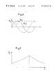
- FIG. 1is a graph of the relationship between the pressure and the axial deflection of the pump rotor
- FIG. 2is a graph of the relationship between the pressure and the through-flow in a pump (“restrictor curve”)
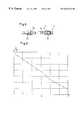
- FIG. 3is an exemplary embodiment of an axial passive journalling of a pump rotor with position sensors for the determination of the position of the rotor
- FIG. 4is a section along the line IV—IV in FIG. 3,
- FIG. 5is an illustration analogous to FIG. 4, however with an axially deflected rotor
- FIG. 6is an exemplary plot of the magnetic flux through position sensors for the determination of the position of the rotor
- FIG. 7is the theoretical plot of the amplitude of the magnetic flux through a position sensor in dependence on the axial deflection of the rotor
- FIG. 8is an exemplary embodiment for an axially displaced arrangement of the position sensors
- FIG. 9is an exemplary plot of the magnetic flux in an arrangement with axially displaced position sensors
- FIG. 10is the theoretical graph of the drive torque in dependence on the drive current at different axial displacements of the rotor
- FIG. 11is an illustration of the relationship between the power and the through-flow in a pump (“power-flux characteristics”)
- FIG. 12is a qualitative illustration of the amplitude of the deflection of the rotor at a varying speed of rotation at two different viscosities of the liquid to be forwarded, and
- FIG. 13is an illustration of the parameter region of a stable control circuit (PD-regulator) of the axial magnetic journalling of the rotor.
- PD-regulatorstable control circuit
- axial forcesact on the pump rotor as a result of the different pressures on the intake side and the output side of a pump (e.g. of a centrifugal pump, a diagonal pump or an axial pump)—thus at both sides of the pump rotor.
- a pumpe.g. of a centrifugal pump, a diagonal pump or an axial pump
- These axial forcesare dependent on the pressure difference between the two sides of the pump rotor. Due to this dependence of the axial forces on the pressure difference it is possible to determine the pressure difference—the “pressure” in the pump—with the help of the axial forces.
- Thisis easily possible in pumps with a magnetic journalling of the pump rotor because the axial forces which act on the pump rotor can be determined very precisely in a magnetic journalling of the pump rotor.
- FIG. 1The relationship between the pressure p (ordinate) and the deflection z of the rotor in the axial direction (abscissa) is illustrated in FIG. 1 for a passive axial magnetic journalling of the rotor for different (angular) rotational frequencies ⁇ .
- the axial deflection z of the rotoris approximately directly proportional to the axial force which acts on the rotor and is thus a measure for the axial force which acts on the rotor.
- This dependence of the pressure p on the axial deflection z of the rotor at different speeds of rotationcan now be stored in the form of an electronic look-up table in the memory of a computer or microprocessor.
- This look-up tableneed be recorded only once for the respective pump type insofar as the manufacture of the individual pump parts remains within predetermined tolerances. It can however also be recorded separately for each individual pump, which improves the precision, but also increases the cost and complexity. In order to reduce the amount of data in this, several support points can be recorded. When deflections arise during operation which lie between the support points then the usual interpolation procedures are used.
- the dependence of the pressure p on the axial deflection z of the rotorcan however also be described by a polynomial.
- the individual coefficients of this polynomialare correspondingly recorded and the pressure p is calculated during operation with the help of the angular rotational frequency w and the axial deflection z.
- a polynomial of this kindcan for example have the form
- a pressure p which is determined with the help of this polynomial of eighth degreerepresents a very good approximation for the actual pressure.
- the precisioncan naturally be further increased through increasing the degree of the polynomial, but the computational effort also naturally increases therein.
- the through-flow Q through the pumpcan subsequently be determined with the help of the pressure-through-flow characteristic (“restrictor curve”) of the pump.
- a restrictor curve of this kindis illustrated in FIG. 2; the relationship between the pressure p in the pump (ordinate) and the through-flow Q (abscissa) at different speeds of rotation ⁇ (or angular speeds of rotation respectively) can be read off from it.
- the restrictor curvecan either again be stored in the form of a look-up table—as described above—or the through-flow can be calculated by a polynomial when the pressure is known (as described above).
- the advantage of this methodnaturally consists on the one hand in that the pressure p and the through-flow Q can be determined without sensors.
- the main advantage howeverconsists in that it is not necessary to know the drive torque of the pump rotor (or, respectively, the motor current, which is proportional to this drive torque). This is a great advantage to the extent that many drive motors for pumps are either supplied with a fixed rotary voltage or—in converter operation—are operated in a voltage controlled manner so that the motor current is not measured at all and is thus not known to the drive regulator as a measured value.
- FIG. 3shows a section along the line IV—IV through the exemplary embodiment in accordance with FIG. 3 .
- the field plotis also qualitatively indicated in these two figures.
- a pump rotor 1which comprises a ring-shaped magnet 10 and an iron yoke 11 .
- the rotor 1is surrounded by a stator 2 , which here has a plurality of teeth 20 with grooves 21 lying between them.
- the arrows in the ring-shaped magnet 10indicate the magnetization direction; the remaining arrows stand qualitatively for the distribution of the magnetic field in this rotor position.
- each position sensors S 1 , S 2 , S 3 , S 4are arranged in each case in grooves 21 between the teeth 20 .
- a magnetic control fluxwhich derives from the windings (not illustrated) which are arranged about the teeth 20 and which serves for the controlling of the rotor position.
- the sensors S 1 , S 2 , S 3 , S 4With the help of the sensors S 1 , S 2 , S 3 , S 4 the direction and strength of the magnetic field in the air gap G and thus the angle of rotation of the rotor 1 can be determined.
- the sensorsare typically designed as Hall sensors.
- the signal of the sensors S 1 , S 2 , S 3 , S 4is now used in order to determine the axial deflection of the rotor.
- the amplitude of the magnetic flux which is measured with the sensorsvaries namely with the axial deflection of the rotor.
- the arrangement of the sensors S 1 , S 2 , S 3 , S 4 in grooves 21is advantageous insofar as the previously mentioned control flux for the controlling of the rotor position is not also measured by the sensors.
- both the angular position and the axial position or deflection respectively of the rotor 1can already be determined by means of two sensors which are not displaced by a multiple of 180°, for example by means of the sensors S 1 and S 2 .
- An example for the magnetic flux ⁇ s through the sensors S 1 , S 2(the signals of the sensors S 3 , S 4 result from the multiplication of the signals of the sensors S 1 , S 2 by the factor ⁇ 1) is illustrated in FIG. 6 .
- ⁇ S1 and ⁇ S2represent the magnetic flux through the sensors S 1 and S 2 .
- FIG. 7a theoretical plot of the amplitude ⁇ s of the magnetic flux ⁇ s through a sensor is now illustrated.
- the magnetic fluxis a maximum when the rotor 1 is in its rest position (no axial deflection) and becomes smaller both for a deflection in the axial direction which is positive and for one which is negative.
- FIG. 9shows the path of the magnetic flux through the sensors in an arrangement with axially displacedly arranged sensors.
- FIG. 10a plot of the drive torque M of this kind in dependence on the drive current I A is shown qualitatively, with the individual straight lines corresponding to different deflections of the rotor from its rest position.
- the uppermost straight linecorresponds to the relationship between the drive current I A and the drive torque M at the rest position of the rotor, the lowermost straight line to the relationship between the drive current I A and the drive torque M at the maximum deflection of the rotor.
- the relationship between the drive torque M and the drive current I Aalso remains to a great extent linear in an axial deflection of the rotor from the rest position.
- ⁇angular rotational frequency
- the through-flow Q through the pumpcan be determined with the help of the power-flux characteristics.
- the power-flux characteristics of FIG. 11 for the pumpcan again be stored in the form of a look-up table, with it being necessary to record these characteristics only once for each pump type insofar as the pump parts remain within predetermined tolerances in the manufacture.
- a polynomial approximationcan be made here as well, as has already been described above.
- the pressure p in the pump which is determined from the axial bearing forceis substantially independent of the viscosity ⁇ of the liquid.
- the viscosity ⁇can finally be determined from the values for p real and p calculated . If the viscosity ⁇ of the liquid is known, then the determination of the pressure p and the through-flow Q with the help of the power-flux characteristics, which are strongly dependent on the viscosity, can subsequently be determined more precisely.
- each magnetic bearingcan be characterized by its stiffness S ML and by its damping D ML . If the magnetically journalled rotor is now located in a liquid, then in comparison with the operation in air, above all the damping is increased.
- the liquid dampingis determined with the help of the shifting of the eigen-frequencies of the rotor.
- Proper oscillations of the bodycan be subdivided into so-called rigid body oscillations, i.e. the body retains its external shape, and in bending oscillations.
- the eigen-frequencies of the rigid body oscillationsare predetermined by the mass and the geometry of the rotor and by the magnetic bearing parameters stiffness S ML and D ML .
- the material dampings of the rotorare also present since the rotor of course deforms in the process.
- the eigen-frequencies of the rotor in airare either known or are determined. If the eigen-frequencies of the rotor in the liquid have been determined in one of the described ways, then the relationship between the shifting of the eigen-frequencies and the viscosity ⁇ resulting therefrom can be stored, e.g. in a look-up table.
- the rotoris operated in the manner of an experiment with a speed of rotation which corresponds to an eigen-frequency of the rotor.
- a speed of rotationwhich corresponds to an eigen-frequency of the rotor.
- the amplitude A of the deflection of the rotoris then a measure for the system damping D tot , from which then the liquid damping D FL and from the latter the viscosity ⁇ can be determined (see e.g. FIG. 12; the broken line represents the liquid with the higher viscosity ⁇ ).
- the amplitude of the deflection and the respective viscosity ⁇ resulting therefromcan then be stored in a look-up table so that the viscosity ⁇ can then be determined from the respective amplitude of the deflection.
- the speed of rotationis varied by a predetermined amount, for example by an amount of ⁇ 10%.
- the axial bearing forcealso varies; in a passive magnetic bearing the axial deflection of the rotor also varies.
- the axial deflectionis less dependent on the viscosity; in the event of a high frequency of variation of the speed of rotation this dependence is stronger. From the measurement at two or more frequencies of variation of the speed of rotation the liquid damping D FL can then be determined, and, from the latter, the viscosity ⁇ .
- This relationship between the variation of the axial bearing force at two or more frequencies of variation of the speed of rotation or between the axial deflection of the rotor at two or more frequencies of variation of the speed of rotation respectively and the viscosity ⁇ resulting therefromcan then for example be stored in a look-up table.
- the shifting of the stability boundary of the closed control circuit for the axial magnetic bearingis determined.
- the parameter region in which a stable operation of the control circuit is possibleis substantially determined by its amplification (the P component) and by its damping (the D component).
- the P componentthe amplification
- the D componentthe damping
- FIG. 13a parameter region of this kind in which a stable operation of the control circuit is possible is illustrated for a simple PD control system by way of example. If the rotor is located in air, then a stable operation of the control circuit is possible within the hatched parameter region.
- a boundary-stable behaviorcan be achieved, that is, the rotor begins to execute continuous oscillations with respect to that regulator axis (there are five such axes: the two axes of horizontal displacement of the rotor in the radial bearing plane, the two tilt axes and the axis of the displacement of the rotor perpendicular to the plane of the bearing) in which the parameter displacement takes place.
- the critical damping D crit of the control circuit itselfis displaced in the direction of a lower critical damping D′ crit because of course an additional damping is produced by the liquid.
- the critical amplification P crit of the control circuit itselfis displaced on the contrary in the direction of a higher critical amplification P′ crit because a portion of the amplification is “eaten up” by the additional damping of the liquid.
- the displacement of the stability boundary of the control circuit for the axial magnetic journalling of the rotoris therefore a measure for the liquid damping D FL , from which then the viscosity ⁇ of the liquid can be determined.
Landscapes
- Physics & Mathematics (AREA)
- General Physics & Mathematics (AREA)
- Magnetic Bearings And Hydrostatic Bearings (AREA)
Abstract
Description
Claims (27)
Applications Claiming Priority (2)
| Application Number | Priority Date | Filing Date | Title |
|---|---|---|---|
| EP98810657 | 1998-07-10 | ||
| EP98810657 | 1998-07-10 |
Publications (1)
| Publication Number | Publication Date |
|---|---|
| US6634224B1true US6634224B1 (en) | 2003-10-21 |
Family
ID=28686070
Family Applications (1)
| Application Number | Title | Priority Date | Filing Date |
|---|---|---|---|
| US09/359,526Expired - LifetimeUS6634224B1 (en) | 1998-07-10 | 1999-07-22 | Method for the determination of the pressure in and/or of the through-flow through a pump |
Country Status (2)
| Country | Link |
|---|---|
| US (1) | US6634224B1 (en) |
| DE (1) | DE59915262D1 (en) |
Cited By (50)
| Publication number | Priority date | Publication date | Assignee | Title |
|---|---|---|---|---|
| US20040173249A1 (en)* | 2001-07-07 | 2004-09-09 | Walter Assmann | Dishwasher comprising spraying arms and a circulating pump |
| US20050287022A1 (en)* | 2004-03-24 | 2005-12-29 | Terumo Kabushiki Kaisha | Blood pump apparatus |
| US20070193635A1 (en)* | 2006-02-23 | 2007-08-23 | Levitronix Llc | Rotary pump, hydrodynamic mixer with a rotary pump, and also the use of the rotary pump for the processing of fluids |
| US7591777B2 (en) | 2004-05-25 | 2009-09-22 | Heartware Inc. | Sensorless flow estimation for implanted ventricle assist device |
| US20100048790A1 (en)* | 2005-07-22 | 2010-02-25 | Imerys Minerals Limited | Particulate Material |
| US20100185280A1 (en)* | 1999-04-23 | 2010-07-22 | Ventrassist Pty. Ltd | Rotary blood pump and control system therefor |
| US8366381B2 (en) | 1997-09-05 | 2013-02-05 | Thoratec Corporation | Rotary pump with hydrodynamically suspended impeller |
| WO2014036419A1 (en) | 2012-08-31 | 2014-03-06 | Thoratec Corporation | Hall sensor mounting in an implantable blood pump |
| WO2014036410A1 (en) | 2012-08-31 | 2014-03-06 | Thoratec Corporation | Start-up algorithm for an implantable blood pump |
| WO2014110202A1 (en) | 2013-01-09 | 2014-07-17 | Imerys Pigments, Inc. | Treatment for non-caking mine rock dust |
| US8827663B2 (en) | 2004-10-18 | 2014-09-09 | Thoratec Corporation | Rotary stability of a rotary pump |
| US8905910B2 (en) | 2010-06-22 | 2014-12-09 | Thoratec Corporation | Fluid delivery system and method for monitoring fluid delivery system |
| US9089635B2 (en) | 2010-06-22 | 2015-07-28 | Thoratec Corporation | Apparatus and method for modifying pressure-flow characteristics of a pump |
| US9091271B2 (en) | 2010-08-20 | 2015-07-28 | Thoratec Corporation | Implantable blood pump |
| WO2016176134A1 (en) | 2015-04-27 | 2016-11-03 | Imerys Pigments, Inc. | Compositions including blends of hydrophobic and non-hydrophobic inorganic particulate material for use in covering products |
| US9526818B2 (en) | 2014-04-15 | 2016-12-27 | Thoratec Corporation | Protective cap for driveline cable connector |
| WO2017015210A1 (en) | 2015-07-20 | 2017-01-26 | Thoratec Corporation | Strain gauge for flow estimation |
| WO2017015268A1 (en) | 2015-07-20 | 2017-01-26 | Thoratec Corporation | Flow estimation using hall-effect sensors |
| US9631492B2 (en) | 2013-07-02 | 2017-04-25 | Imerys Usa, Inc. | Non-caking rock dust for use in underground coal mines |
| US9629948B2 (en) | 2014-04-15 | 2017-04-25 | Tc1 Llc | Methods for upgrading ventricle assist devices |
| CN106860929A (en)* | 2017-01-16 | 2017-06-20 | 哈尔滨理工大学 | A kind of blood pump that suspension type impeller displacement measurement is coupled for magnetic liquid |
| US9694123B2 (en) | 2014-04-15 | 2017-07-04 | Tc1 Llc | Methods and systems for controlling a blood pump |
| US9744280B2 (en) | 2014-04-15 | 2017-08-29 | Tc1 Llc | Methods for LVAD operation during communication losses |
| US9786150B2 (en) | 2014-04-15 | 2017-10-10 | Tci Llc | Methods and systems for providing battery feedback to patient |
| CN107466238A (en)* | 2015-04-13 | 2017-12-12 | 柏林心脏有限公司 | Pump and the method for running the pump for fluid |
| US9849224B2 (en) | 2014-04-15 | 2017-12-26 | Tc1 Llc | Ventricular assist devices |
| CN107530479A (en)* | 2015-04-29 | 2018-01-02 | 柏林心脏有限公司 | The method of pump configuration and operation fluid pump |
| WO2018057795A1 (en) | 2016-09-26 | 2018-03-29 | Tc1 Llc | Heart pump driveline power modulation |
| US9938970B2 (en) | 2011-12-16 | 2018-04-10 | Fluid Handling Llc | Best-fit affinity sensorless conversion means or technique for pump differential pressure and flow monitoring |
| WO2018201134A1 (en) | 2017-04-28 | 2018-11-01 | Tc1 Llc | Patient adapter for driveline cable and methods |
| WO2019183126A1 (en) | 2018-03-20 | 2019-09-26 | Tc1 Llc | Mechanical gauge for estimating inductance changes in resonant power transfer systems with flexible coils for use with implanted medical devices |
| US10533417B2 (en) | 2013-01-09 | 2020-01-14 | Imerys Usa, Inc. | Non-caking mine rock dust for use in underground coal mines |
| EP3597231A1 (en) | 2018-07-17 | 2020-01-22 | Tc1 Llc | Systems and methods for inertial sensing for vad diagnostics and closed loop control |
| WO2020068333A1 (en) | 2018-09-25 | 2020-04-02 | Tc1 Llc | Adaptive speed control algorithms and controllers for optimizing flow in ventricular assist devices |
| US10702641B2 (en) | 2015-06-29 | 2020-07-07 | Tc1 Llc | Ventricular assist devices having a hollow rotor and methods of use |
| US10722632B2 (en) | 2015-08-28 | 2020-07-28 | Tc1 Llc | Blood pump controllers and methods of use for improved energy efficiency |
| US10780209B2 (en) | 2017-03-29 | 2020-09-22 | Tc1 Llc | Adjusting pump protocol based on irregular heart rhythm |
| US10835654B2 (en) | 2017-03-29 | 2020-11-17 | Tc1 Llc | Pressure sensing ventricular assist devices and methods of use |
| US10973967B2 (en) | 2018-01-10 | 2021-04-13 | Tc1 Llc | Bearingless implantable blood pump |
| US11065436B2 (en) | 2017-03-29 | 2021-07-20 | Tc1 Llc | Communication methods and architecture for heart treatment systems |
| US11167123B2 (en) | 2018-03-19 | 2021-11-09 | Tc1 Llc | Coordinated ventricular assist and cardiac rhythm management devices and methods |
| US11421694B2 (en) | 2019-02-01 | 2022-08-23 | White Knight Fluid Handling Inc. | Pump having magnets for journaling and magnetically axially positioning rotor thereof, and related methods |
| US11517740B2 (en) | 2018-03-15 | 2022-12-06 | Tc1 Llc | Methods for controlling a left ventricular assist device |
| WO2023158493A1 (en) | 2022-02-16 | 2023-08-24 | Tc1 Llc | Real time heart rate monitoring for close loop control and/or artificial pulse synchronization of implantable ventricular assist devices |
| WO2023229899A1 (en) | 2022-05-26 | 2023-11-30 | Tc1 Llc | Tri-axis accelerometers for patient physiologic monitoring and closed loop control of implantable ventricular assist devices |
| WO2023235230A1 (en) | 2022-06-02 | 2023-12-07 | Tc1 Llc | Implanted connector booster sealing for implantable medical devices |
| WO2024050319A1 (en) | 2022-08-29 | 2024-03-07 | Tc1 Llc | Implantable electrical connector assembly |
| WO2024097236A1 (en) | 2022-11-01 | 2024-05-10 | Tc1 Llc | Assessment and management of adverse event risks in mechanical circulatory support patients |
| WO2024131262A1 (en)* | 2022-12-20 | 2024-06-27 | 上海炫脉医疗科技有限公司 | Method and device for measuring blood pressure at outlet of blood pump |
| WO2025137296A1 (en) | 2023-12-22 | 2025-06-26 | Tc1 Llc | Utilization of a left-ventricular pressure sensor for measurement of left-atrial and aortic pressure |
Citations (14)
| Publication number | Priority date | Publication date | Assignee | Title |
|---|---|---|---|---|
| US3649137A (en)* | 1970-11-30 | 1972-03-14 | Nikolaus Laing | Centrifugal pump with magnetic coupling |
| US4341111A (en) | 1979-03-05 | 1982-07-27 | Fresenius Ag | Process and apparatus for determining the visco elastic characteristics of fluids |
| US4779614A (en) | 1987-04-09 | 1988-10-25 | Nimbus Medical, Inc. | Magnetically suspended rotor axial flow blood pump |
| US4781525A (en) | 1987-07-17 | 1988-11-01 | Minnesota Mining And Manufacturing Company | Flow measurement system |
| US5036236A (en)* | 1990-05-07 | 1991-07-30 | Hughes Aircraft Company | Air gap matching proximity sensor for magnetic bearings |
| US5104284A (en)* | 1990-12-17 | 1992-04-14 | Dresser-Rand Company | Thrust compensating apparatus |
| US5127792A (en)* | 1988-08-22 | 1992-07-07 | Ebara Corporation | Centrifugal pump having magnet bearing |
| US5350283A (en)* | 1991-12-04 | 1994-09-27 | Ntn Corporation | Clean pump |
| WO1996031934A1 (en)* | 1995-04-03 | 1996-10-10 | Sulzer Electronics Ag | Rotary machine with an electromagnetic rotary drive |
| US5613831A (en) | 1994-07-25 | 1997-03-25 | Sulzer Pumpen Ag | Apparatus for thrust compensation on shaft of rotary pump |
| US5725357A (en) | 1995-04-03 | 1998-03-10 | Ntn Corporation | Magnetically suspended type pump |
| US5857348A (en)* | 1993-06-15 | 1999-01-12 | Multistack International Limited | Compressor |
| US5911558A (en)* | 1996-05-10 | 1999-06-15 | Ntn Corporation | Magnetically suspended pump having position sensing control |
| US6074180A (en)* | 1996-05-03 | 2000-06-13 | Medquest Products, Inc. | Hybrid magnetically suspended and rotated centrifugal pumping apparatus and method |
- 1999
- 1999-07-02DEDE59915262Tpatent/DE59915262D1/ennot_activeExpired - Lifetime
- 1999-07-22USUS09/359,526patent/US6634224B1/ennot_activeExpired - Lifetime
Patent Citations (15)
| Publication number | Priority date | Publication date | Assignee | Title |
|---|---|---|---|---|
| US3649137A (en)* | 1970-11-30 | 1972-03-14 | Nikolaus Laing | Centrifugal pump with magnetic coupling |
| US4341111A (en) | 1979-03-05 | 1982-07-27 | Fresenius Ag | Process and apparatus for determining the visco elastic characteristics of fluids |
| US4779614A (en) | 1987-04-09 | 1988-10-25 | Nimbus Medical, Inc. | Magnetically suspended rotor axial flow blood pump |
| US4781525A (en) | 1987-07-17 | 1988-11-01 | Minnesota Mining And Manufacturing Company | Flow measurement system |
| US5127792A (en)* | 1988-08-22 | 1992-07-07 | Ebara Corporation | Centrifugal pump having magnet bearing |
| US5036236A (en)* | 1990-05-07 | 1991-07-30 | Hughes Aircraft Company | Air gap matching proximity sensor for magnetic bearings |
| US5104284A (en)* | 1990-12-17 | 1992-04-14 | Dresser-Rand Company | Thrust compensating apparatus |
| US5350283A (en)* | 1991-12-04 | 1994-09-27 | Ntn Corporation | Clean pump |
| US5857348A (en)* | 1993-06-15 | 1999-01-12 | Multistack International Limited | Compressor |
| US5613831A (en) | 1994-07-25 | 1997-03-25 | Sulzer Pumpen Ag | Apparatus for thrust compensation on shaft of rotary pump |
| WO1996031934A1 (en)* | 1995-04-03 | 1996-10-10 | Sulzer Electronics Ag | Rotary machine with an electromagnetic rotary drive |
| US5725357A (en) | 1995-04-03 | 1998-03-10 | Ntn Corporation | Magnetically suspended type pump |
| US6100618A (en)* | 1995-04-03 | 2000-08-08 | Sulzer Electronics Ag | Rotary machine with an electromagnetic rotary drive |
| US6074180A (en)* | 1996-05-03 | 2000-06-13 | Medquest Products, Inc. | Hybrid magnetically suspended and rotated centrifugal pumping apparatus and method |
| US5911558A (en)* | 1996-05-10 | 1999-06-15 | Ntn Corporation | Magnetically suspended pump having position sensing control |
Cited By (107)
| Publication number | Priority date | Publication date | Assignee | Title |
|---|---|---|---|---|
| US8366381B2 (en) | 1997-09-05 | 2013-02-05 | Thoratec Corporation | Rotary pump with hydrodynamically suspended impeller |
| US20100185280A1 (en)* | 1999-04-23 | 2010-07-22 | Ventrassist Pty. Ltd | Rotary blood pump and control system therefor |
| US8282359B2 (en) | 1999-04-23 | 2012-10-09 | Thoratec Corporation | Rotary blood pump and control system therefor |
| US8870552B2 (en) | 1999-04-23 | 2014-10-28 | Thoratec Corporation | Rotary blood pump and control system therefor |
| US7100623B2 (en)* | 2001-07-07 | 2006-09-05 | Miele & Cie. Kg | Dishwasher having spray arms and a circulation pump |
| US20040173249A1 (en)* | 2001-07-07 | 2004-09-09 | Walter Assmann | Dishwasher comprising spraying arms and a circulating pump |
| US7748964B2 (en) | 2004-03-24 | 2010-07-06 | Terumo Kabushiki Kaisha | Blood pump apparatus |
| US20100221130A1 (en)* | 2004-03-24 | 2010-09-02 | Terumo Kabushiki Kaisha | Blood pump apparatus |
| US20050287022A1 (en)* | 2004-03-24 | 2005-12-29 | Terumo Kabushiki Kaisha | Blood pump apparatus |
| US8430652B2 (en) | 2004-03-24 | 2013-04-30 | Terumo Kabushiki Kaisha | Blood pump apparatus |
| US8506470B2 (en) | 2004-05-25 | 2013-08-13 | Heartware, Inc. | Sensorless flow estimation for implanted ventricle assist device |
| US20110137108A1 (en)* | 2004-05-25 | 2011-06-09 | Heartware, Inc. | Sensorless flow estimation for implanted ventricle assist device |
| US8961390B2 (en) | 2004-05-25 | 2015-02-24 | Heartware, Inc. | Sensorless flow estimation for implanted ventricle assist device |
| US7591777B2 (en) | 2004-05-25 | 2009-09-22 | Heartware Inc. | Sensorless flow estimation for implanted ventricle assist device |
| US8827663B2 (en) | 2004-10-18 | 2014-09-09 | Thoratec Corporation | Rotary stability of a rotary pump |
| US20100048790A1 (en)* | 2005-07-22 | 2010-02-25 | Imerys Minerals Limited | Particulate Material |
| US20070193635A1 (en)* | 2006-02-23 | 2007-08-23 | Levitronix Llc | Rotary pump, hydrodynamic mixer with a rotary pump, and also the use of the rotary pump for the processing of fluids |
| US8092074B2 (en)* | 2006-02-23 | 2012-01-10 | Levitronix Technologies, LLC | Rotary pump, hydrodynamic mixer with a rotary pump, and also the use of the rotary pump for the processing of fluids |
| US9839733B2 (en) | 2010-06-22 | 2017-12-12 | Tc1 Llc | Apparatus and method for modifying pressure-flow characteristics of a pump |
| US8905910B2 (en) | 2010-06-22 | 2014-12-09 | Thoratec Corporation | Fluid delivery system and method for monitoring fluid delivery system |
| US9089635B2 (en) | 2010-06-22 | 2015-07-28 | Thoratec Corporation | Apparatus and method for modifying pressure-flow characteristics of a pump |
| US9675741B2 (en) | 2010-08-20 | 2017-06-13 | Tc1 Llc | Implantable blood pump |
| US9091271B2 (en) | 2010-08-20 | 2015-07-28 | Thoratec Corporation | Implantable blood pump |
| US10500321B2 (en) | 2010-08-20 | 2019-12-10 | Tc1 Llc | Implantable blood pump |
| US9938970B2 (en) | 2011-12-16 | 2018-04-10 | Fluid Handling Llc | Best-fit affinity sensorless conversion means or technique for pump differential pressure and flow monitoring |
| US10413650B2 (en) | 2012-08-31 | 2019-09-17 | Tc1 Llc | Hall sensor mounting in an implantable blood pump |
| US9492599B2 (en) | 2012-08-31 | 2016-11-15 | Thoratec Corporation | Hall sensor mounting in an implantable blood pump |
| US10485911B2 (en) | 2012-08-31 | 2019-11-26 | Tc1 Llc | Sensor mounting in an implantable blood pump |
| WO2014036419A1 (en) | 2012-08-31 | 2014-03-06 | Thoratec Corporation | Hall sensor mounting in an implantable blood pump |
| US9579436B2 (en) | 2012-08-31 | 2017-02-28 | Thoratec Corporation | Sensor mounting in an implantable blood pump |
| US9427510B2 (en) | 2012-08-31 | 2016-08-30 | Thoratec Corporation | Start-up algorithm for an implantable blood pump |
| WO2014036410A1 (en) | 2012-08-31 | 2014-03-06 | Thoratec Corporation | Start-up algorithm for an implantable blood pump |
| US9731058B2 (en) | 2012-08-31 | 2017-08-15 | Tc1 Llc | Start-up algorithm for an implantable blood pump |
| US11421531B2 (en) | 2013-01-09 | 2022-08-23 | Imerys Usa, Inc. | Non-caking mine rock dust for use in underground coal mines |
| WO2014110202A1 (en) | 2013-01-09 | 2014-07-17 | Imerys Pigments, Inc. | Treatment for non-caking mine rock dust |
| US10533417B2 (en) | 2013-01-09 | 2020-01-14 | Imerys Usa, Inc. | Non-caking mine rock dust for use in underground coal mines |
| US9631492B2 (en) | 2013-07-02 | 2017-04-25 | Imerys Usa, Inc. | Non-caking rock dust for use in underground coal mines |
| US9526818B2 (en) | 2014-04-15 | 2016-12-27 | Thoratec Corporation | Protective cap for driveline cable connector |
| US10388142B2 (en) | 2014-04-15 | 2019-08-20 | Tc1 Llc | Methods and systems for providing battery feedback to patient |
| US9789237B2 (en) | 2014-04-15 | 2017-10-17 | Tc1 Llc | Systems for upgrading ventricle assist devices |
| US10500324B2 (en) | 2014-04-15 | 2019-12-10 | Tc1 Llc | Systems for LVAD operation during communication losses |
| US9744280B2 (en) | 2014-04-15 | 2017-08-29 | Tc1 Llc | Methods for LVAD operation during communication losses |
| US9849224B2 (en) | 2014-04-15 | 2017-12-26 | Tc1 Llc | Ventricular assist devices |
| US10398819B2 (en) | 2014-04-15 | 2019-09-03 | Tci Llc | Ventricular assist devices |
| US9629948B2 (en) | 2014-04-15 | 2017-04-25 | Tc1 Llc | Methods for upgrading ventricle assist devices |
| US9786150B2 (en) | 2014-04-15 | 2017-10-10 | Tci Llc | Methods and systems for providing battery feedback to patient |
| US9694123B2 (en) | 2014-04-15 | 2017-07-04 | Tc1 Llc | Methods and systems for controlling a blood pump |
| US9937284B2 (en) | 2014-04-15 | 2018-04-10 | Tc1 Llc | Systems for upgrading ventricle assist devices |
| US10115290B2 (en) | 2014-04-15 | 2018-10-30 | Tci Llc | Methods and systems for providing battery feedback to patient |
| US10111996B2 (en) | 2014-04-15 | 2018-10-30 | Tc1 Llc | Ventricular assist devices |
| US10207039B2 (en) | 2014-04-15 | 2019-02-19 | Tc1 Llc | Methods and systems for upgrading ventricle assist devices |
| CN107466238B (en)* | 2015-04-13 | 2021-08-27 | 柏林心脏有限公司 | Pump and method for operating a pump for a fluid |
| US10660999B2 (en) | 2015-04-13 | 2020-05-26 | Berlin Heart Gmbh | Pump, and method for operating a pump for fluids |
| CN107466238A (en)* | 2015-04-13 | 2017-12-12 | 柏林心脏有限公司 | Pump and the method for running the pump for fluid |
| WO2016176134A1 (en) | 2015-04-27 | 2016-11-03 | Imerys Pigments, Inc. | Compositions including blends of hydrophobic and non-hydrophobic inorganic particulate material for use in covering products |
| US10695475B2 (en) | 2015-04-29 | 2020-06-30 | Berlin Heart Gmbh | Pump arrangement and method of operating a fluid pump |
| CN107530479A (en)* | 2015-04-29 | 2018-01-02 | 柏林心脏有限公司 | The method of pump configuration and operation fluid pump |
| US10702641B2 (en) | 2015-06-29 | 2020-07-07 | Tc1 Llc | Ventricular assist devices having a hollow rotor and methods of use |
| US10300184B2 (en) | 2015-07-20 | 2019-05-28 | Tc1 Llc | Flow estimation using hall-effect sensors |
| US10722630B2 (en) | 2015-07-20 | 2020-07-28 | Tc1 Llc | Strain gauge for flow estimation |
| US11872384B2 (en) | 2015-07-20 | 2024-01-16 | Tc1 Llc | Method of operating a blood pump having a magnetically levitated impeller |
| US11806517B2 (en) | 2015-07-20 | 2023-11-07 | Tc1 Llc | Impeller displacement based flow estimation |
| WO2017015210A1 (en) | 2015-07-20 | 2017-01-26 | Thoratec Corporation | Strain gauge for flow estimation |
| WO2017015268A1 (en) | 2015-07-20 | 2017-01-26 | Thoratec Corporation | Flow estimation using hall-effect sensors |
| US11040188B2 (en) | 2015-07-20 | 2021-06-22 | Tc1 Llc | Flow estimation using hall-effect sensors and/or magnetic bearing currents |
| US9901666B2 (en) | 2015-07-20 | 2018-02-27 | Tc1 Llc | Flow estimation using hall-effect sensors for measuring impeller eccentricity |
| US10722632B2 (en) | 2015-08-28 | 2020-07-28 | Tc1 Llc | Blood pump controllers and methods of use for improved energy efficiency |
| US11224737B2 (en) | 2015-08-28 | 2022-01-18 | Tc1 Llc | Blood pump controllers and methods of use for improved energy efficiency |
| WO2018057795A1 (en) | 2016-09-26 | 2018-03-29 | Tc1 Llc | Heart pump driveline power modulation |
| US12144975B2 (en) | 2016-09-26 | 2024-11-19 | Tc1 Llc | Heart pump driveline power modulation |
| US10933182B2 (en) | 2016-09-26 | 2021-03-02 | Tci Llc | Heart pump driveline power modulation |
| CN106860929B (en)* | 2017-01-16 | 2019-02-01 | 哈尔滨理工大学 | A kind of blood pump for magnetic liquid coupling suspension type impeller displacement measurement |
| CN106860929A (en)* | 2017-01-16 | 2017-06-20 | 哈尔滨理工大学 | A kind of blood pump that suspension type impeller displacement measurement is coupled for magnetic liquid |
| US12029535B2 (en) | 2017-03-29 | 2024-07-09 | Tc1 Llc | Communication methods and architecture for heart treatment systems |
| US11065436B2 (en) | 2017-03-29 | 2021-07-20 | Tc1 Llc | Communication methods and architecture for heart treatment systems |
| US11478629B2 (en) | 2017-03-29 | 2022-10-25 | Tc1 Llc | Adjusting pump protocol based on irregular heart rhythm |
| US10835654B2 (en) | 2017-03-29 | 2020-11-17 | Tc1 Llc | Pressure sensing ventricular assist devices and methods of use |
| US11779234B2 (en) | 2017-03-29 | 2023-10-10 | Tc1 Llc | Pressure sensing ventricular assist devices and methods of use |
| US12383156B2 (en) | 2017-03-29 | 2025-08-12 | Tc1 Llc | Pressure sensing ventricular assist devices and methods of use |
| US10780209B2 (en) | 2017-03-29 | 2020-09-22 | Tc1 Llc | Adjusting pump protocol based on irregular heart rhythm |
| US10737007B2 (en) | 2017-04-28 | 2020-08-11 | Tc1 Llc | Patient adapter for driveline cable and methods |
| WO2018201134A1 (en) | 2017-04-28 | 2018-11-01 | Tc1 Llc | Patient adapter for driveline cable and methods |
| US10973967B2 (en) | 2018-01-10 | 2021-04-13 | Tc1 Llc | Bearingless implantable blood pump |
| US12383725B2 (en) | 2018-01-10 | 2025-08-12 | Tc1 Llc | Bearingless implantable blood pump |
| US11517740B2 (en) | 2018-03-15 | 2022-12-06 | Tc1 Llc | Methods for controlling a left ventricular assist device |
| US12390170B2 (en) | 2018-03-15 | 2025-08-19 | Tc1 Llc | Methods and systems for controlling a left ventricular assist device |
| US11167123B2 (en) | 2018-03-19 | 2021-11-09 | Tc1 Llc | Coordinated ventricular assist and cardiac rhythm management devices and methods |
| WO2019183126A1 (en) | 2018-03-20 | 2019-09-26 | Tc1 Llc | Mechanical gauge for estimating inductance changes in resonant power transfer systems with flexible coils for use with implanted medical devices |
| US11689057B2 (en) | 2018-03-20 | 2023-06-27 | Tc1 Llc | Mechanical gauge for estimating inductance changes in resonant power transfer systems with flexible coils for use with implanted medical devices |
| US10940251B2 (en) | 2018-03-20 | 2021-03-09 | Tc1 Llc | Mechanical gauge for estimating inductance changes in resonant power transfer systems with flexible coils for use with implanted medical devices |
| EP4190392A1 (en) | 2018-07-17 | 2023-06-07 | Tc1 Llc | Systems and methods for inertial sensing for vad diagnostics and closed loop control |
| EP3597231A1 (en) | 2018-07-17 | 2020-01-22 | Tc1 Llc | Systems and methods for inertial sensing for vad diagnostics and closed loop control |
| US11241570B2 (en) | 2018-07-17 | 2022-02-08 | Tc1 Llc | Systems and methods for inertial sensing for VAD diagnostics and closed loop control |
| US12064612B2 (en) | 2018-07-17 | 2024-08-20 | Tc1 Llc | Systems and methods for inertial sensing for VAD diagnostics and closed loop control |
| EP4360691A2 (en) | 2018-09-25 | 2024-05-01 | Tc1 Llc | Adaptive speed control algorithms and controllers for optimizing flow in ventricular assist devices |
| US11998730B2 (en) | 2018-09-25 | 2024-06-04 | Tc1 Llc | Adaptive speed control algorithms and controllers for optimizing flow in ventricular assist devices |
| US11241572B2 (en) | 2018-09-25 | 2022-02-08 | Tc1 Llc | Adaptive speed control algorithms and controllers for optimizing flow in ventricular assist devices |
| WO2020068333A1 (en) | 2018-09-25 | 2020-04-02 | Tc1 Llc | Adaptive speed control algorithms and controllers for optimizing flow in ventricular assist devices |
| US12012965B2 (en) | 2019-02-01 | 2024-06-18 | White Knight Fluid Handling Inc. | Pump having opposing magnets between a rotor and stator, and related assemblies, systems, and methods |
| US11421694B2 (en) | 2019-02-01 | 2022-08-23 | White Knight Fluid Handling Inc. | Pump having magnets for journaling and magnetically axially positioning rotor thereof, and related methods |
| WO2023158493A1 (en) | 2022-02-16 | 2023-08-24 | Tc1 Llc | Real time heart rate monitoring for close loop control and/or artificial pulse synchronization of implantable ventricular assist devices |
| WO2023229899A1 (en) | 2022-05-26 | 2023-11-30 | Tc1 Llc | Tri-axis accelerometers for patient physiologic monitoring and closed loop control of implantable ventricular assist devices |
| WO2023235230A1 (en) | 2022-06-02 | 2023-12-07 | Tc1 Llc | Implanted connector booster sealing for implantable medical devices |
| WO2024050319A1 (en) | 2022-08-29 | 2024-03-07 | Tc1 Llc | Implantable electrical connector assembly |
| WO2024097236A1 (en) | 2022-11-01 | 2024-05-10 | Tc1 Llc | Assessment and management of adverse event risks in mechanical circulatory support patients |
| WO2024131262A1 (en)* | 2022-12-20 | 2024-06-27 | 上海炫脉医疗科技有限公司 | Method and device for measuring blood pressure at outlet of blood pump |
| WO2025137296A1 (en) | 2023-12-22 | 2025-06-26 | Tc1 Llc | Utilization of a left-ventricular pressure sensor for measurement of left-atrial and aortic pressure |
Also Published As
| Publication number | Publication date |
|---|---|
| DE59915262D1 (en) | 2011-06-01 |
Similar Documents
| Publication | Publication Date | Title |
|---|---|---|
| US6634224B1 (en) | Method for the determination of the pressure in and/or of the through-flow through a pump | |
| US6129660A (en) | Method of controlling blood pump | |
| KR100447052B1 (en) | Servo control device | |
| US7501782B2 (en) | Method and apparatus for controlling a magnetic bearing device | |
| JP6558501B2 (en) | Magnetic bearing device and fluid mechanical system using the same | |
| US10823632B2 (en) | Method for measuring the unbalance of flexible rotors by means of position-measuring sensors | |
| US6711943B1 (en) | Method for the determination of the viscosity of a liquid such as blood | |
| Zad et al. | Design and analysis of a novel bearingless motor for a miniature axial flow blood pump | |
| CA2264173A1 (en) | Integrated controller pump | |
| Zhu et al. | Rotordynamic performance of flexure pivot hydrostatic gas bearings for oil-free turbomachinery | |
| Kim et al. | In situ runout identification in active magnetic bearing system by extended influence coefficient method | |
| US20010033115A1 (en) | Brushless spindle DC motor used as an actuator to create radial force | |
| US5284053A (en) | Controlled flow volumetric flowmeter | |
| EP2740954B1 (en) | Magnetic bearing apparatus and method for reducing vibration caused by magnetic bearing apparatus | |
| JPH08270595A (en) | Magnetic levitation pump | |
| Bently et al. | Active controlled hydrostatic bearings for a new generation of machines | |
| JP4139444B2 (en) | Method and structure for exciting shaft winding and drive winding system of electric machine having magnetic bearing and electric drive device | |
| Yang et al. | Radial displacement measurement method in bearingless slice motor through eddy current displacement sensors positioned on the underside of the rotor | |
| WO1980001898A1 (en) | Axial gap permanent magnet motor | |
| Schöb et al. | The Bearingless centrifugal pump-A perfect example of a mechatronics system | |
| Zhou et al. | Reluctance force magnetic suspension characteristics and control for cylindrical rotor bearingless motors | |
| Hilton et al. | Test controller design, implementation, and performance for a magnetic suspension continuous flow ventricular assist device | |
| US20040212333A1 (en) | Motor control system, motor apparatus, vacuum pump, correction current value measuring apparatus, and motor control method | |
| JP2002071532A (en) | Reaction measuring device for mechanical element | |
| US3531700A (en) | Variable speed drive arrangement for an analytical instrument |
Legal Events
| Date | Code | Title | Description |
|---|---|---|---|
| AS | Assignment | Owner name:SULZER ELECTRONICS AG, SWITZERLAND Free format text:ASSIGNMENT OF ASSIGNORS INTEREST;ASSIGNORS:SCHOEB, RETO;BARLETTA, NATALE;HAHN, JUERGEN;REEL/FRAME:010124/0394 Effective date:19990511 Owner name:LUST ANTRIEBSTECHNIK GMBH, GERMANY Free format text:ASSIGNMENT OF ASSIGNORS INTEREST;ASSIGNORS:SCHOEB, RETO;BARLETTA, NATALE;HAHN, JUERGEN;REEL/FRAME:010124/0394 Effective date:19990511 | |
| AS | Assignment | Owner name:LEVITRONIX LLC, MASSACHUSETTS Free format text:ASSIGNMENT OF ASSIGNORS INTEREST;ASSIGNORS:SULZER ELECTRONICS AG;LUST ANTRIEBSTECHNIK GMBH;REEL/FRAME:011922/0270;SIGNING DATES FROM 20010308 TO 20010430 | |
| STCF | Information on status: patent grant | Free format text:PATENTED CASE | |
| CC | Certificate of correction | ||
| FPAY | Fee payment | Year of fee payment:4 | |
| REFU | Refund | Free format text:REFUND - PAYMENT OF FILING FEES UNDER 1.28(C) (ORIGINAL EVENT CODE: R1461); ENTITY STATUS OF PATENT OWNER: LARGE ENTITY Free format text:REFUND - PAYMENT OF MAINTENANCE FEE UNDER 1.28(C) (ORIGINAL EVENT CODE: R1559); ENTITY STATUS OF PATENT OWNER: LARGE ENTITY | |
| FEPP | Fee payment procedure | Free format text:PAT HOLDER NO LONGER CLAIMS SMALL ENTITY STATUS, ENTITY STATUS SET TO UNDISCOUNTED (ORIGINAL EVENT CODE: STOL); ENTITY STATUS OF PATENT OWNER: LARGE ENTITY | |
| SULP | Surcharge for late payment | ||
| FEPP | Fee payment procedure | Free format text:PAT HOLDER CLAIMS SMALL ENTITY STATUS, ENTITY STATUS SET TO SMALL (ORIGINAL EVENT CODE: LTOS); ENTITY STATUS OF PATENT OWNER: LARGE ENTITY | |
| FPAY | Fee payment | Year of fee payment:8 | |
| AS | Assignment | Owner name:THORATEC LLC, CALIFORNIA Free format text:CHANGE OF NAME;ASSIGNOR:LEVITRONIX LLC;REEL/FRAME:026772/0729 Effective date:20110803 | |
| FEPP | Fee payment procedure | Free format text:PAYOR NUMBER ASSIGNED (ORIGINAL EVENT CODE: ASPN); ENTITY STATUS OF PATENT OWNER: LARGE ENTITY | |
| FEPP | Fee payment procedure | Free format text:PAT HOLDER NO LONGER CLAIMS SMALL ENTITY STATUS, ENTITY STATUS SET TO UNDISCOUNTED (ORIGINAL EVENT CODE: STOL); ENTITY STATUS OF PATENT OWNER: LARGE ENTITY | |
| SULP | Surcharge for late payment | ||
| FPAY | Fee payment | Year of fee payment:12 |