US6634217B1 - Live line method and tool for identifying electrical conductors - Google Patents
Live line method and tool for identifying electrical conductorsDownload PDFInfo
- Publication number
- US6634217B1 US6634217B1US10/107,184US10718402AUS6634217B1US 6634217 B1US6634217 B1US 6634217B1US 10718402 AUS10718402 AUS 10718402AUS 6634217 B1US6634217 B1US 6634217B1
- Authority
- US
- United States
- Prior art keywords
- testing
- tool
- wire
- hardness
- target
- Prior art date
- Legal status (The legal status is an assumption and is not a legal conclusion. Google has not performed a legal analysis and makes no representation as to the accuracy of the status listed.)
- Expired - Fee Related
Links
- 238000000034methodMethods0.000titleclaimsabstractdescription12
- 239000004020conductorSubstances0.000titledescription5
- 238000012360testing methodMethods0.000claimsabstractdescription33
- 238000007542hardness measurementMethods0.000claimsabstractdescription21
- 238000009826distributionMethods0.000claimsabstractdescription14
- 238000007373indentationMethods0.000claimsdescription28
- 229910001369BrassInorganic materials0.000claimsdescription2
- 239000010951brassSubstances0.000claimsdescription2
- 239000002184metalSubstances0.000claims7
- RYGMFSIKBFXOCR-UHFFFAOYSA-NCopperChemical compound[Cu]RYGMFSIKBFXOCR-UHFFFAOYSA-N0.000description14
- 235000019589hardnessNutrition0.000description12
- 229910052802copperInorganic materials0.000description4
- 239000010949copperSubstances0.000description4
- 229910000831SteelInorganic materials0.000description3
- 239000010959steelSubstances0.000description3
- 238000012986modificationMethods0.000description2
- 230000004048modificationEffects0.000description2
- 229910000838Al alloyInorganic materials0.000description1
- 229910001150Cartridge brassInorganic materials0.000description1
- 206010014405ElectrocutionDiseases0.000description1
- HCHKCACWOHOZIP-UHFFFAOYSA-NZincChemical compound[Zn]HCHKCACWOHOZIP-UHFFFAOYSA-N0.000description1
- 230000032683agingEffects0.000description1
- 230000004075alterationEffects0.000description1
- XAGFODPZIPBFFR-UHFFFAOYSA-NaluminiumChemical compound[Al]XAGFODPZIPBFFR-UHFFFAOYSA-N0.000description1
- 229910052782aluminiumInorganic materials0.000description1
- 238000010276constructionMethods0.000description1
- 238000005520cutting processMethods0.000description1
- 238000004519manufacturing processMethods0.000description1
- 239000000463materialSubstances0.000description1
- 239000000203mixtureSubstances0.000description1
- 238000000926separation methodMethods0.000description1
- 239000000126substanceSubstances0.000description1
- 239000002699waste materialSubstances0.000description1
- 239000011701zincSubstances0.000description1
- 229910052725zincInorganic materials0.000description1
Images


Classifications
- G—PHYSICS
- G01—MEASURING; TESTING
- G01N—INVESTIGATING OR ANALYSING MATERIALS BY DETERMINING THEIR CHEMICAL OR PHYSICAL PROPERTIES
- G01N3/00—Investigating strength properties of solid materials by application of mechanical stress
- G01N3/40—Investigating hardness or rebound hardness
- G01N3/42—Investigating hardness or rebound hardness by performing impressions under a steady load by indentors, e.g. sphere, pyramid
- B—PERFORMING OPERATIONS; TRANSPORTING
- B60—VEHICLES IN GENERAL
- B60M—POWER SUPPLY LINES, AND DEVICES ALONG RAILS, FOR ELECTRICALLY- PROPELLED VEHICLES
- B60M1/00—Power supply lines for contact with collector on vehicle
- B60M1/12—Trolley lines; Accessories therefor
- B60M1/28—Manufacturing or repairing trolley lines
- H—ELECTRICITY
- H02—GENERATION; CONVERSION OR DISTRIBUTION OF ELECTRIC POWER
- H02G—INSTALLATION OF ELECTRIC CABLES OR LINES, OR OF COMBINED OPTICAL AND ELECTRIC CABLES OR LINES
- H02G1/00—Methods or apparatus specially adapted for installing, maintaining, repairing or dismantling electric cables or lines
- H02G1/005—Methods or apparatus specially adapted for installing, maintaining, repairing or dismantling electric cables or lines for cutting cables or wires, or splicing
- G—PHYSICS
- G01—MEASURING; TESTING
- G01N—INVESTIGATING OR ANALYSING MATERIALS BY DETERMINING THEIR CHEMICAL OR PHYSICAL PROPERTIES
- G01N2203/00—Investigating strength properties of solid materials by application of mechanical stress
- G01N2203/0058—Kind of property studied
- G01N2203/0069—Fatigue, creep, strain-stress relations or elastic constants
- G—PHYSICS
- G01—MEASURING; TESTING
- G01N—INVESTIGATING OR ANALYSING MATERIALS BY DETERMINING THEIR CHEMICAL OR PHYSICAL PROPERTIES
- G01N2203/00—Investigating strength properties of solid materials by application of mechanical stress
- G01N2203/02—Details not specific for a particular testing method
- G01N2203/0202—Control of the test
- G01N2203/0212—Theories, calculations
- H—ELECTRICITY
- H01—ELECTRIC ELEMENTS
- H01R—ELECTRICALLY-CONDUCTIVE CONNECTIONS; STRUCTURAL ASSOCIATIONS OF A PLURALITY OF MUTUALLY-INSULATED ELECTRICAL CONNECTING ELEMENTS; COUPLING DEVICES; CURRENT COLLECTORS
- H01R2201/00—Connectors or connections adapted for particular applications
- H01R2201/20—Connectors or connections adapted for particular applications for testing or measuring purposes
Definitions
- the inventionrelates to tools for handling live electrical conductors, and more particularly to a method and tool for testing the hardness of a live electrical conductor.
- Copper wirehas been widely used in the past as the material of construction for electrical power distribution lines. Some distribution lines contain soft annealed copper wire, while others contain hard drawn or medium hard drawn copper wire. Hard drawn and medium hard drawn wire have a considerably higher minimum breaking strength than soft annealed wire. When soft annealed copper wire distribution lines are restrung due to aging, there is a risk of breakage and in-service failure.
- the present inventionprovides a method of live testing of the hardness of a target electrical distribution wire having a known gauge.
- the methodcomprises a) providing a hardness testing tool at the operating end of an insulated tool for manipulating live distribution lines, wherein the hardness testing tool comprises a testing surface of known hardness; b) forcing the testing surface against the target wire; and c)comparing the resultant degree of deformation or lack of deformation on the testing surface with the expected degree of deformation which would occur for wire of that gauge having a specific hardness.
- the present inventionfurther provides a tool for live testing of the hardness of a target electrical distribution wire having a known gauge.
- the toolcomprises an elongated insulated handle and is provided at the operating end thereof with a hardness testing element, wherein the hardness testing element comprises a testing surface of known hardness, the hardness testing element being adapted to force the testing surface against the target wire.
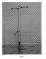
- FIG. 1is a perspective view of a tool according to the invention
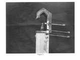
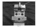
- FIGS. 2 and 3are front and side views respectively of the prior art tool head
- FIGS. 4 and 5are front and side views respectively showing the upper screw threaded end of the prior art tool head shown in FIGS. 2 and 3;
- FIG. 6is a partial perspective view of the nested rotatable inner pole of the tool shown in FIG. 1;
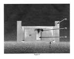
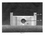
- FIGS. 7 through 10are front, side, top and bottom views respectively of the indentation block holder according to the invention with the indentation block removed;
- FIGS. 11 and 12are front and side views respectively of the indentation block holder according to the invention with the indentation block in place;
- FIGS. 13 and 14are front and side views respectively of the indentation block and test surface
- FIGS. 15 and 16are front and side views respectively of the indentation block holder according to the invention with the indentation block in place installed in the tool head;
- FIGS. 17 and 18are partial perspective views illustrating the location of the load indicator and its arrangement with respect to the hot stick.
- FIGS. 19 and 20, respectively,illustrate the surface of the indentation block after testing of medium hard drawn and soft annealed #6 copper wire.
- the present invention 10 shown in FIG. 1comprises a “hot stick” modified to allow hardness testing.
- Hot sticksare manufactured to allow workers to handle live electrical distribution lines without risk of electrocution. For example, they may be used when splicing or disconnecting live power lines.
- FIG. 1A hot stick modified according to the invention is shown in FIG. 1 .
- the inventioncomprises an elongated, insulated hollow cylindrical outer pole 12 . It has a modified tool head 14 and a modified nested rotatable inner pole 16 .
- the nested rotatable inner pole 16 prior to modificationis shown in FIG. 6 . It extends within, and is rotatable within, outer pole 12 . It is connected to an upper screw threaded end 18 , shown in FIGS. 4 and 5, which extends through a threaded nut (not shown) secured in the end 21 of outer pole 12 adjacent the tool head 14 whereby rotation of inner pole 16 causes the connector end 20 of threaded end 18 to extend from, or be drawn back towards, the end 21 .
- a wire supporting piece 22is rotatably connected to connector end 20 and can be moved towards or away from hook 24 to clamp the tool head to a wire, or release the tool head from the wire.
- the tool head 14is modified by replacing the existing wire supporting piece 22 with an indentation block holder 26 , shown in FIGS. 7 through 12.
- the indentation block holderholds the indentation block 28 in place. It can be machined from a free cutting brass (C36000).
- the indentation block holderhas three cylindrical cavities: cavity 30 for the receiving end 20 (FIG. 5) and two cavities 70 for two steel cylinders 74 ; and a rectangular cavity 32 for receiving the indentation block 28 .
- Two magnets 76are permanently embedded in cavities 70 as shown in FIG. 12 .
- Screws 34together with a faceplate 72 , steel cylinders 74 , magnets 76 and a set screw 78 , hold the indentation block 28 in place.
- Steel cylinders 74 and magnets 76assist in retaining indentation block 28 by magnetic attraction, while set screw 78 can be tightened against indentation block 28 to retain it.
- Arms 36ensure that the holder moves in alignment with the tool head 14
- Indentation block 28is shown in FIGS. 11, 12 , 13 , and 14 .
- the hardness of the block 28is selected so that the target wire will be too soft to indent the upper surface of the block when forced against it, but the harder copper wire will cause an indentation.
- Itserves to differentiate wires of different hardnesses. It has a body portion 40 which typically forms a block about 0.25′′ ⁇ 0.30′′ ⁇ 0.50′′ and a tapered upper portion 42 with an upper planar surface 43 , typically 0.30′′ ⁇ 0.16′′.
- Aperture 41receives set screw 78 .
- FIGS. 11 and 12show the indentation block 28 seated in the holder 26 .
- FIGS. 15 and 16show the holder 26 with the indentation block 28 in place and fastened onto the head of the screw threaded end 18 in tool head 14 .
- the block 28is aligned to be perpendicular to the wire to be tested when held in tool head 14 .
- Load indicatorsare added to the bottom of the hot stick 10 , shown in FIG. 1, to provide a pre-determined load as illustrated in FIGS. 17 and 18.
- FIG. 17shows indicator elements 50 and 52 , which form two separate lower and upper matching units fixed to inner pole 16 and outer pole 12 , respectively.
- Element 50rotates with pole 16 while element 52 is fixed to pole 12 .
- Element 50comprises a pointer 51 and element 52 comprises pointers 53 , 55 .
- the width of the separation 54represents the rotative force needed to properly indent the indentation block.
- the indicator elementsare made of aluminum alloy 6061-T6. The indicator controls the loading that is the expected contact force between the indentation block and the copper wire. It is important that the operator tighten the hot stick with a controlled force. Too much or too little force will produce an unexpected result.
- the head of tool 14is placed over the bare, uninsulated wire to be tested 60 so that the wire extends through space A in FIG. 16 .
- the inner poleis rotated clockwise until it reaches a position where the lower indicator 55 is in alignment with the upper pointer 51 as shown in FIG. 17 .
- the operatorthen rotates the inner pole farther, tightening the indentation block 28 against the test wire until the lower indicator 53 is in alignment with the upper pointer 51 , as shown in FIG. 18 .
- the inner poleis then loosened and the hot stick is removed from the test wire.
- the surface 43 of the indentation block 28is examined. If it displays a significant indentation from the wire, as in FIG. 19, then the wire is hard or medium hard drawn and need not be replaced. If it does not display a significant indentation from the wire, as in FIG. 20, then the wire is soft annealed and requires replacement.
Landscapes
- Engineering & Computer Science (AREA)
- General Health & Medical Sciences (AREA)
- Life Sciences & Earth Sciences (AREA)
- Chemical & Material Sciences (AREA)
- Analytical Chemistry (AREA)
- Biochemistry (AREA)
- Physics & Mathematics (AREA)
- General Physics & Mathematics (AREA)
- Immunology (AREA)
- Pathology (AREA)
- Health & Medical Sciences (AREA)
- Manufacturing & Machinery (AREA)
- Mechanical Engineering (AREA)
- Investigating Strength Of Materials By Application Of Mechanical Stress (AREA)
Abstract
Description
Claims (15)
Priority Applications (2)
| Application Number | Priority Date | Filing Date | Title |
|---|---|---|---|
| US10/107,184US6634217B1 (en) | 2002-03-28 | 2002-03-28 | Live line method and tool for identifying electrical conductors |
| CA002379750ACA2379750A1 (en) | 2002-03-28 | 2002-03-28 | Live line method and tool for indentifying electrical conductors |
Applications Claiming Priority (2)
| Application Number | Priority Date | Filing Date | Title |
|---|---|---|---|
| US10/107,184US6634217B1 (en) | 2002-03-28 | 2002-03-28 | Live line method and tool for identifying electrical conductors |
| CA002379750ACA2379750A1 (en) | 2002-03-28 | 2002-03-28 | Live line method and tool for indentifying electrical conductors |
Publications (2)
| Publication Number | Publication Date |
|---|---|
| US20030182992A1 US20030182992A1 (en) | 2003-10-02 |
| US6634217B1true US6634217B1 (en) | 2003-10-21 |
Family
ID=29737441
Family Applications (1)
| Application Number | Title | Priority Date | Filing Date |
|---|---|---|---|
| US10/107,184Expired - Fee RelatedUS6634217B1 (en) | 2002-03-28 | 2002-03-28 | Live line method and tool for identifying electrical conductors |
Country Status (2)
| Country | Link |
|---|---|
| US (1) | US6634217B1 (en) |
| CA (1) | CA2379750A1 (en) |
Families Citing this family (1)
| Publication number | Priority date | Publication date | Assignee | Title |
|---|---|---|---|---|
| CN105911317A (en)* | 2016-07-05 | 2016-08-31 | 国网辽宁省电力有限公司丹东供电公司 | Novel grounding probe of groundmeter |
Citations (5)
| Publication number | Priority date | Publication date | Assignee | Title |
|---|---|---|---|---|
| US4079978A (en)* | 1976-12-03 | 1978-03-21 | Hastings Fiber Glass Products, Inc. | Hot stick with air cushion |
| US4535623A (en)* | 1983-02-11 | 1985-08-20 | Paul Gilberto | Material hardness testing apparatus |
| US5337566A (en)* | 1993-03-18 | 1994-08-16 | Burndy Corporation | Powder actuated compression tool |
| US5341088A (en)* | 1984-06-22 | 1994-08-23 | Davis Murray W | System for rating electric power transmission lines and equipment |
| US5397982A (en)* | 1992-09-25 | 1995-03-14 | Cooper Industries, Inc. | Releasable sensor for conductor fault detection including a rigid trigger arm |
- 2002
- 2002-03-28CACA002379750Apatent/CA2379750A1/ennot_activeAbandoned
- 2002-03-28USUS10/107,184patent/US6634217B1/ennot_activeExpired - Fee Related
Patent Citations (5)
| Publication number | Priority date | Publication date | Assignee | Title |
|---|---|---|---|---|
| US4079978A (en)* | 1976-12-03 | 1978-03-21 | Hastings Fiber Glass Products, Inc. | Hot stick with air cushion |
| US4535623A (en)* | 1983-02-11 | 1985-08-20 | Paul Gilberto | Material hardness testing apparatus |
| US5341088A (en)* | 1984-06-22 | 1994-08-23 | Davis Murray W | System for rating electric power transmission lines and equipment |
| US5397982A (en)* | 1992-09-25 | 1995-03-14 | Cooper Industries, Inc. | Releasable sensor for conductor fault detection including a rigid trigger arm |
| US5337566A (en)* | 1993-03-18 | 1994-08-16 | Burndy Corporation | Powder actuated compression tool |
Also Published As
| Publication number | Publication date |
|---|---|
| US20030182992A1 (en) | 2003-10-02 |
| CA2379750A1 (en) | 2003-09-28 |
Similar Documents
| Publication | Publication Date | Title |
|---|---|---|
| US8267730B2 (en) | Device for connecting two electrical conductors | |
| US12025551B2 (en) | Method and equipment for determining conditions of stiction between a braking element and an element to be braked | |
| JP2017150075A (en) | Cathodic Protection Monitoring Probe | |
| CN108931544B (en) | Sample holding device and testing method for in-situ electron backscattering diffraction research | |
| US6634217B1 (en) | Live line method and tool for identifying electrical conductors | |
| US4760327A (en) | Cable status testing | |
| US4210373A (en) | Ground clamp for welding apparatus | |
| KR101721527B1 (en) | Electrical Cnnection Device for Safety Diagnosis of Reinforced Concrete Structure | |
| CN220289720U (en) | DC current testing clamp for grounding end of loop resistance tester | |
| CN205263131U (en) | A auxiliary device for 10kv vacuum circuit breaker high -voltage testing | |
| US4461168A (en) | Hydrogen embrittlement tester | |
| US1370651A (en) | Stick for handling high-voltage line conductors | |
| CN207165437U (en) | Insulating bar | |
| KR20150011867A (en) | Cable connection device | |
| CN210307283U (en) | A clamping device for grinding and polishing the section of thin sample | |
| JPH11304603A (en) | Method and apparatus for measuring residual stress | |
| JPH1133732A (en) | Earth side splicing equipment for electric welder | |
| Mantha | Spot Welding Protocol | |
| CN216085383U (en) | A multi-purpose pile head structure and grounding pile | |
| US2309886A (en) | Electrode holder | |
| CN111769373B (en) | A portable screw-in broken leather type wiring clip | |
| US1997963A (en) | Terminal attachment | |
| ATE319099T1 (en) | DEVICE AND METHOD FOR DETERMINING THE VOLTAGE FREENESS OF MULTIPHASE ELECTRICAL CABLES | |
| KR200450320Y1 (en) | Lead Cable Connection Structure of Lead Body for Measuring Equipment | |
| EP4518056A1 (en) | Removal of insulation sheath from power cable |
Legal Events
| Date | Code | Title | Description |
|---|---|---|---|
| AS | Assignment | Owner name:BRITISH COLUMBIA HYDRO AND POWER AUTHORITY, CANADA Free format text:ASSIGNMENT OF ASSIGNORS INTEREST;ASSIGNORS:BHUYAN, GOURI S.;RAO, AVARAI S.;KANG, CHIEN;AND OTHERS;REEL/FRAME:012740/0343 Effective date:20020322 Owner name:POWERTECH LABS INC., CANADA Free format text:ASSIGNMENT OF ASSIGNORS INTEREST;ASSIGNORS:BHUYAN, GOURI S.;RAO, AVARAI S.;KANG, CHIEN;AND OTHERS;REEL/FRAME:012740/0343 Effective date:20020322 Owner name:BRITISH COLUMBIA HYDRO AND POWER AUTHORITY,CANADA Free format text:ASSIGNMENT OF ASSIGNORS INTEREST;ASSIGNORS:BHUYAN, GOURI S.;RAO, AVARAI S.;KANG, CHIEN;AND OTHERS;REEL/FRAME:012740/0343 Effective date:20020322 Owner name:POWERTECH LABS INC.,CANADA Free format text:ASSIGNMENT OF ASSIGNORS INTEREST;ASSIGNORS:BHUYAN, GOURI S.;RAO, AVARAI S.;KANG, CHIEN;AND OTHERS;REEL/FRAME:012740/0343 Effective date:20020322 | |
| FPAY | Fee payment | Year of fee payment:4 | |
| REMI | Maintenance fee reminder mailed | ||
| LAPS | Lapse for failure to pay maintenance fees | ||
| STCH | Information on status: patent discontinuation | Free format text:PATENT EXPIRED DUE TO NONPAYMENT OF MAINTENANCE FEES UNDER 37 CFR 1.362 | |
| FP | Lapsed due to failure to pay maintenance fee | Effective date:20111021 |