US6633676B1 - Encoding a video signal - Google Patents
Encoding a video signalDownload PDFInfo
- Publication number
- US6633676B1 US6633676B1US09/572,993US57299300AUS6633676B1US 6633676 B1US6633676 B1US 6633676B1US 57299300 AUS57299300 AUS 57299300AUS 6633676 B1US6633676 B1US 6633676B1
- Authority
- US
- United States
- Prior art keywords
- pictures
- picture
- resolution
- motion
- series
- Prior art date
- Legal status (The legal status is an assumption and is not a legal conclusion. Google has not performed a legal analysis and makes no representation as to the accuracy of the status listed.)
- Expired - Fee Related
Links
Images


Classifications
- H—ELECTRICITY
- H04—ELECTRIC COMMUNICATION TECHNIQUE
- H04N—PICTORIAL COMMUNICATION, e.g. TELEVISION
- H04N19/00—Methods or arrangements for coding, decoding, compressing or decompressing digital video signals
- H04N19/50—Methods or arrangements for coding, decoding, compressing or decompressing digital video signals using predictive coding
- H04N19/503—Methods or arrangements for coding, decoding, compressing or decompressing digital video signals using predictive coding involving temporal prediction
- H04N19/51—Motion estimation or motion compensation
- H04N19/53—Multi-resolution motion estimation; Hierarchical motion estimation
- G—PHYSICS
- G06—COMPUTING OR CALCULATING; COUNTING
- G06T—IMAGE DATA PROCESSING OR GENERATION, IN GENERAL
- G06T3/00—Geometric image transformations in the plane of the image
- G06T3/40—Scaling of whole images or parts thereof, e.g. expanding or contracting
- G06T3/4007—Scaling of whole images or parts thereof, e.g. expanding or contracting based on interpolation, e.g. bilinear interpolation
- H—ELECTRICITY
- H04—ELECTRIC COMMUNICATION TECHNIQUE
- H04N—PICTORIAL COMMUNICATION, e.g. TELEVISION
- H04N19/00—Methods or arrangements for coding, decoding, compressing or decompressing digital video signals
- H04N19/10—Methods or arrangements for coding, decoding, compressing or decompressing digital video signals using adaptive coding
- H04N19/102—Methods or arrangements for coding, decoding, compressing or decompressing digital video signals using adaptive coding characterised by the element, parameter or selection affected or controlled by the adaptive coding
- H04N19/117—Filters, e.g. for pre-processing or post-processing
- H—ELECTRICITY
- H04—ELECTRIC COMMUNICATION TECHNIQUE
- H04N—PICTORIAL COMMUNICATION, e.g. TELEVISION
- H04N19/00—Methods or arrangements for coding, decoding, compressing or decompressing digital video signals
- H04N19/10—Methods or arrangements for coding, decoding, compressing or decompressing digital video signals using adaptive coding
- H04N19/134—Methods or arrangements for coding, decoding, compressing or decompressing digital video signals using adaptive coding characterised by the element, parameter or criterion affecting or controlling the adaptive coding
- H04N19/167—Position within a video image, e.g. region of interest [ROI]
- H—ELECTRICITY
- H04—ELECTRIC COMMUNICATION TECHNIQUE
- H04N—PICTORIAL COMMUNICATION, e.g. TELEVISION
- H04N19/00—Methods or arrangements for coding, decoding, compressing or decompressing digital video signals
- H04N19/10—Methods or arrangements for coding, decoding, compressing or decompressing digital video signals using adaptive coding
- H04N19/169—Methods or arrangements for coding, decoding, compressing or decompressing digital video signals using adaptive coding characterised by the coding unit, i.e. the structural portion or semantic portion of the video signal being the object or the subject of the adaptive coding
- H04N19/17—Methods or arrangements for coding, decoding, compressing or decompressing digital video signals using adaptive coding characterised by the coding unit, i.e. the structural portion or semantic portion of the video signal being the object or the subject of the adaptive coding the unit being an image region, e.g. an object
- H—ELECTRICITY
- H04—ELECTRIC COMMUNICATION TECHNIQUE
- H04N—PICTORIAL COMMUNICATION, e.g. TELEVISION
- H04N19/00—Methods or arrangements for coding, decoding, compressing or decompressing digital video signals
- H04N19/40—Methods or arrangements for coding, decoding, compressing or decompressing digital video signals using video transcoding, i.e. partial or full decoding of a coded input stream followed by re-encoding of the decoded output stream
- H—ELECTRICITY
- H04—ELECTRIC COMMUNICATION TECHNIQUE
- H04N—PICTORIAL COMMUNICATION, e.g. TELEVISION
- H04N19/00—Methods or arrangements for coding, decoding, compressing or decompressing digital video signals
- H04N19/50—Methods or arrangements for coding, decoding, compressing or decompressing digital video signals using predictive coding
- H04N19/59—Methods or arrangements for coding, decoding, compressing or decompressing digital video signals using predictive coding involving spatial sub-sampling or interpolation, e.g. alteration of picture size or resolution
- H—ELECTRICITY
- H04—ELECTRIC COMMUNICATION TECHNIQUE
- H04N—PICTORIAL COMMUNICATION, e.g. TELEVISION
- H04N7/00—Television systems
- H04N7/01—Conversion of standards, e.g. involving analogue television standards or digital television standards processed at pixel level
- H04N7/0135—Conversion of standards, e.g. involving analogue television standards or digital television standards processed at pixel level involving interpolation processes
- H04N7/014—Conversion of standards, e.g. involving analogue television standards or digital television standards processed at pixel level involving interpolation processes involving the use of motion vectors
Definitions
- the inventionrelates to a method of encoding a video signal comprising a series of pictures in a motion-compensated encoder, said method comprising the steps of receiving the series of pictures and estimating motion vectors in the series of pictures with sub-resolution accuracy.
- the inventionalso relates to a motion-compensated encoder for encoding a video signal comprising a series of pictures, said encoder comprising receiving means for receiving the series of pictures, estimation means for estimating motion vectors in the series of pictures with sub-resolution accuracy, a picture memory for storing the pictures, and means for forming and supplying a motion-compensated encoded video signal by means of the picture memory.
- the inventionfurther relates to a camera system comprising an image sensor for picking up a video signal which comprises a series of pictures, and a motion-compensated encoder.
- the article by Regis Saint Girons “The digital simulcast AD-HDTV coding system”, IEEE Trans. on Consumer Electr. Vol. 38, No. 4, November 1992, pp. 778-782describes an Advanced Digital High Definition Television System which comprises an MPEG video encoder.
- a video signalis received after it has been processed in a preprocessor.
- the encodercomprises a device for estimating motion.
- the articledescribes a technique for estimating motion in macroblocks of 16 ⁇ 16 pixels with half-pixel accuracy.
- Motion vectorsare generated which indicate the motion of a macroblock in a picture with respect to a previous picture. When a motion vector is known, pixel values can be predicted for a macroblock from a previous, reconstructed picture.
- the predicted pixel valuesare subtracted from the actual pixel values of the relevant macroblock.
- the differenceis a residual macroblock.
- the residual macroblockis further encoded and applied, together with the motion vectors, to an output of the encoder. In this way, use is made of time redundance in the video signal.
- the method according to the inventionis characterized in that it comprises the step of making a choice between generating and supplying a motion-compensated encoded video signal and generating and supplying a higher-resolution picture having a higher resolution than the pictures of the series, if the motion-compensated encoded video signal is generated, forming the motion-compensated encoded video signal by means of the picture memory, and if the higher-resolution picture is generated, forming the higher-resolution picture from the series of pictures and the motion vectors by means of a picture memory. Forming a higher-resolution picture is based on the availability of sub-resolution motion information and on the presence of aliasing in the video signal.
- the information present in various picturesis thus used for forming a new picture with a higher resolution.
- the resolutionis the extent of fineness or focus of the picture. In many cases, the resolution will correspond to the number of pixels from which the picture is built up. If a number of pixels is jointly used for displaying the picture information of one pixel, the number of pixels may be larger than the resolution. This occurs, for example, when using a color filter grating which samples color channels through a limited set of pixels, or when projecting a picture on a larger number of pixels without increasing the picture contents.
- Sub-resolution accuracyinvolves a greater accuracy than the fineness or focus of the picture and corresponds in many cases to sub-pixel accuracy.
- the known methodsare used for displaying the video signal.
- the enhancement of resolution in accordance with the inventionis, however, performed when encoding the video signal in a motion-compensated encoder.
- European patent application EP 0 731 600describes that the video signal can be remote-displayed via a communication network, this patent application does not give any indication about encoding the video signal in a motion-compensated encoder.
- An advantage of enhancing the resolution in a motion-compensated encoderis that means for estimating motion are already present in such an encoder.
- the motion estimator present in the motion-compensated encoder and the picture memoryare used to advantage, both for generating the motion-compensated encoded video signal and for generating the higher-resolution picture.
- a series of pictures with a higher resolutionis supplied from an output of the encoder.
- the series of picturesis adapted to a predetermined standard output signal. This may be, for example, a standard number of pictures per second.
- Another, generally larger number of lower-resolution pictures per secondcan be applied to the input, which lower-resolution pictures are used for forming the standard number of pictures at the output with a higher resolution, dependent on the video signal.
- Two higher-resolution picturescan be combined to one interlaced picture.
- the inventionrequires storage space for storing the various pictures from the series. This means that there should be more storage space in an encoder in which the resolution is enhanced than in an encoder in which the resolution is not enhanced, because more pictures are generally stored in the case of resolution enhancement.
- An embodiment complying with the quantity of required storage spaceis characterized in that the method comprises the steps of selecting a predetermined region of interest from the video signal and storing the series of pictures in the picture memory, the pictures relating to the region of interest.
- the region of interestforms a sub-signal of the video signal.
- the region of interestis a preselected sub-region of the display supplied by the video signal. The choice of the region of interest is passed on to the encoder, whereafter the region of interest is selected from the video signal.
- the sub-pictures relating to the region of interestoccupy less space than the full pictures.
- the conventional picture memoryis the picture memory which is present in a comparable encoder in which no higher-resolution picture is formed. In this way, an inexpensive and practical method is possible for enhancing the resolution.
- a series of sub-pictures of a region of interestis combined to one picture having a higher resolution than the separate sub-pictures, which higher-resolution picture preferably has the same number of pixels as a normal picture.
- the motionis preferably estimated in a hybrid encoder in which both motion compensation and other encoding operations are performed.
- An exampleis MPEG.
- An MPEG encoderalready comprises standard means for estimating motion and generating motion vectors, and a picture memory for storing the various pictures. A higher-resolution picture may be supplied as an intracoded frame.
- An MPEG decodercan decode it without additional information.
- Another example of a compression techniqueis H.263.
- the motion-compensated encoder according to the inventionis characterized in that the encoder comprises combination means for forming and supplying a higher-resolution picture from the series of pictures and the motion vectors by means of the picture memory, said higher-resolution picture having a higher resolution than the pictures of the series.
- the camera system according to the inventioncomprises an image sensor for picking up the video signal, and a motion-compensated encoder for encoding the video signal according to the invention.
- the integration of an encoder according to the invention in a camera systemhas the advantage that it is simpler to obtain the series of pictures at a high rate.
- the inventionis very suitable for sensor-encoder integration.
- FIG. 1shows a device comprising a known encoder.
- FIG. 2shows an embodiment of a device according to the invention.
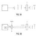
- FIGS. 3A, 3 Billustrate the input and output of an encoder in a preferred embodiment according to the invention.
- FIG. 1shows a device comprising a known encoder. It is a camera system 1 comprising an image sensor 2 and a hybrid encoder 3 .
- Encoder 3comprises receiving means 30 , a motion estimator 31 , a motion compensator 32 and a picture memory 33 .
- the encoderalso comprises a subtracter circuit 34 and an adder circuit 35 .
- the operation of a known encoderwill be roughly explained with reference to FIG. 1 .
- the pictures F 1,2 . . .are present in a video signal coming from the image sensor 2 and are received in the receiving means 30 in the encoder 3 . Means which may be present for preprocessing the video signal are not shown.
- a first picture F 1is applied to the subtracter circuit 34 and to the motion estimator 31 . This first picture is encoded without using motion estimation and motion compensation. This means that nothing is subtracted from this first picture F 1 in the subtracter circuit 34 . It is common practice to subject the picture after the subtracter circuit 34 to various encoding operations so as to compress the signal. In these operations, use is made of the spatial redundance in the pictures.
- Examples of these encoding operationsare Discrete Cosine Transform (DCT) in combination with adaptive quantization, differential coding, run-length coding (RLC) and variable-length coding (VLC). Means for performing these encoding operations are not directly important for the invention and are therefore not shown in the Figure for the sake of clarity.
- DCTDiscrete Cosine Transform
- RVLCrun-length coding
- VLCvariable-length coding
- Means for performing these encoding operationsare not directly important for the invention and are therefore not shown in the Figure for the sake of clarity.
- I(ntracoded) pictureSince the first picture F 1 is only subjected to the above-mentioned encoding operations and is not subjected to motion compensation, the result of the encoding operation of the first picture is referred to as I(ntracoded) picture.
- the I pictureis applied to the output of the encoder 3 and also to adder circuit 35 . Since no motion compensation has taken place, nothing is added to the I picture in the adder
- Motion estimation and motion compensationis used for a second picture F 2 .
- the second picture F 2is compared with the F 1 ′ picture reconstructed from the I picture, stored in the memory 33 and being ideally identical to the first picture F 1 .
- Per macroblockmotion in the second picture is estimated with respect to the F 1 ′ picture.
- motion vectors mare generated which are passed on to an output of the encoder 3 .
- a motion-compensated picture associated with these motion vectors mis computed in the motion compensator 32 . This is done on the basis of the F 1 ′ picture which is stored in the memory 33 .
- the motion-compensated pictureis subtracted in the subtracter circuit 34 from the second picture F 2 , which results in a residual second picture.
- the residual second pictureis further compressed in accordance with the various encoding methods mentioned hereinbefore.
- the resultis referred to as a P(redictively coded) or B(idirectionally coded) picture, dependent on the motion compensation used.
- the distinction between P and B picturesis not important for the invention.
- the residual second picturemay be added in the adder circuit 35 to the motion-compensated picture so that a reconstructed second picture is obtained which can be stored in the picture memory 33 for further use for motion compensation.
- FIG. 2shows an embodiment of a camera system 1 according to the invention.
- the camera system in this embodimentcomprises selection means 36 for selecting a region of interest (ROI) from the video signal coming from the image sensor 2 .
- the selection means 36are shown in FIG. 2 within the encoder, but they may alternatively be present outside the encoder 3 , in the image sensor 2 or elsewhere.
- the region of interestis predetermined, for example, by a user watching a display on a display screen. The user may choose, for example, a region of interest because he wants to zoom in on a given partial region of the picture picked up by the image sensor 2 .
- the selection means 36are notified in a predetermined manner, which is not important for the invention, what should be selected as a region of interest from the video signal.
- a signal S(ROI)is applied to the selection means 36 in the embodiment shown, which signal defines the region of interest.
- the selection means 36select the data from the video signal associated with the region of interest and pass on these data.
- the pictures F 1,2,3, . . . in the video signal, coming from the image sensor 2are reduced to sub-pictures f 1,2,3, . . . by the selection means 36 , which sub-pictures only relate to the region of interest. These sub-pictures f 1,2,3, . . .
- various sub-pictures f 1,2,3, . . .can be stored in the same picture memory 33 , dependent on the size of the region of interest and on the picture memory 33 . If various sub-pictures f 1,2,3, . . . are available, they may be used for enhancing the resolution in accordance with the known methods.
- the result of the resolution enhancementis one picture I H having a higher resolution than the sub-pictures f 1,2,3, . . . of the series.
- the higher-resolution picture I His generally subjected to the previously mentioned various-encoding operations.
- the I H picturehas the same format as a standard I picture as described with reference to FIG. 1.
- a subsequent series of sub-pictures f 1,2,3, . . .is required for a subsequent higher-resolution picture I H .
- a signal having a given number of sub-pictures f 1,2,3, . . . per secondis thus converted into a signal having a smaller or equal number of pictures I H per second but with a higher resolution per picture I H .
- the resolution enhancementmay be performed in accordance with the method as known from the previously mentioned European patent application EP 0 731 600.
- a methodis described in which one of the pictures with a lower resolution is selected as the reference picture.
- the relative motion between the pixels of the reference picture and each of the other picturesis estimated with a sub-resolution accuracy.
- the lower-resolution picturesare scaled with reference to the high-resolution domain and combined for forming the high-resolution picture.
- the relative motionis represented in the form of a mapping transform.
- the higher-resolution picture I His preferably formed from the series of sub-pictures f 1,2,3, . . . while using motion vectors m which are generated in a motion estimation process 31 . This may be done, for example, in accordance with the method as described in the previously mentioned article by Debin Chen et al. In accordance with the Chen method, the resolution of an I picture is enhanced while using the next P and B pictures and the associated motion vectors m. These pictures are up-sampled whereafter a reduced sub-pixel searching process starts for matching macroblocks with the up-sampled video picture while using the half pixel motion vectors m as initial value conditions.
- the motion vectors mare directly used for matching or interpolating the macroblocks with the up-sampled video picture.
- the motion estimator 31 and the picture memory 33are already present in a standard encoder as shown in, for example, FIG. 1 .
- Components which are further necessaryare a vector memory 37 for storing motion vectors, and an interpolator 38 .
- a complicated addressing schemeis necessary because several pictures must be stored simultaneously in the memory and further used for reconstructing the higher-resolution picture I H .
- a great advantageis that when enhancing the resolution in the encoder 3 , many components already present in a known standard encoder 3 can be used, the most important of which are the motion estimator 31 and the picture memory 33 .
- the sub-pictures f 1,2,3, . . . from the seriesare not encoded pictures such as I, B and P pictures but sub-pictures f 1,2,3, . . . of pictures F 1,2,3, . . . as come in from the receiving means 30 from the image sensor 2 .
- These sub-pictures f 1,2,3, . . .do not need to be decoded first.
- the sub-pictures f 1,2,3, . . . from the video signalare not only passed on to the picture memory 33 for the resolution enhancement but also to the motion estimator 31 .
- a first sub-picture f 1is applied to the picture memory 33 without motion being estimated.
- the motionis preferably estimated with respect to the sub-picture preceding and/or succeeding said sub-picture. The reason is that this yields a better result for the motion estimation than the use of a reference picture.
- the motion vectors m obtainedare stored in the vector memory 37 .
- the phase of storing sub-pictures f 1,2,3, . . . , the estimation of motion and the storage of the motion vectors mmay be referred to as the “collection phase”. This is a first phase of the resolution enhancement.
- a second phaseis the construction of the higher-resolution picture I H .
- This phasemay be referred to as the “interpolation phase”. Interpolation is preferably performed while using the motion vectors m.
- the sub-pictures f 1,2,3, . . . which are stored in the picture memory 33are interpolated to a higher-resolution picture I H by means of the motion vectors m. This interpolation takes place in an interpolator 38 .
- Interpolator 38is coupled to the picture memory 33 and to the vector memory 37 .
- Interpolator 38constructs the higher-resolution picture I H from the series of sub-pictures f 1,2,3, . . .
- interpolationis that it can be performed in a relatively simple and rapid way.
- the higher-resolution picture I His further compressed in the conventional manner.
- This picture I His passed on as a normal I picture in this embodiment.
- Successive higher-resolution pictures I Hcan be passed on without motion compensation taking place. It is alternatively possible to perform motion compensation on the higher-resolution pictures I H .
- a method as described with reference to FIG. 1is required, for which storage space is necessary in the picture memory 33 or in another memory.
- the picture memoryrequires extension or no extension.
- a control unit 39determines whether the encoder supplies a motion-compensated encoded video signal or a higher-resolution picture I H .
- FIGS. 3A, 3 Billustrate the input and output of the encoder 3 in accordance with a preferred embodiment of the invention.
- FIG. 3Ashows a normal video mode, as described with reference to FIG. 1 .
- Input pictures F 1,2, . . . relating to a display Xare applied to the encoder 3 and encoded therein.
- the outputconsists of encoded pictures I, B, P.
- FIG. 3Bshows a ROI video mode.
- a region of interest ROIis chosen from the video signal and forms a sub-region of the display X.
- the sub-pictures f 1,2,3, . . . relating to the region of interest ROIare sub-pictures of pictures F 1,2,3, . . . which relate to the display X.
- the sub-pictures f 1,2,3, . . .are selected in the selection means 36 from the pictures F 1,2,3, . . . , dependent on signal S(ROI).
- the input f 1,2,3, . . .is used in the encoder 2 for forming the higher-resolution pictures I H .
- the output signalcomplies with the same standard and can be decoded with the same decoder.
- an I H picturecorresponds for a decoder to a normal I picture. It is necessary for this embodiment that the pictures of the region of interest f 1,2,3, . . . are available at a sufficiently high rate.
- a combination of the encoder 3 with the image sensor 2 as shown in FIG. 2provides the advantage that it is easier to obtain pictures f 1,2,3, . . . at a high rate from the sensor 2 , and that it is also easier to adapt the encoder 3 to the sensor 2 .
- the picture memory 33requires an extension or no extension.
- the regions of interests ROIare chosen to be such that it is possible to enhance the resolution in the encoder without extending the picture memory 33 with respect to the normal video mode. Then it is possible to perform both a normal mode (see FIGS. 1 and 3A) and a ROI video mode (see FIGS. 2 and 3B) with a minimum number of extra components. If the picture memory 33 is extended, it is also possible to use more and/or larger regions of interests ROI for the entire display X, or for using I, B, P sequences.
- An example of a practical embodiment of the inventionis a CMOS PC camera.
Landscapes
- Engineering & Computer Science (AREA)
- Multimedia (AREA)
- Signal Processing (AREA)
- Physics & Mathematics (AREA)
- General Physics & Mathematics (AREA)
- Theoretical Computer Science (AREA)
- Compression Or Coding Systems Of Tv Signals (AREA)
- Compression, Expansion, Code Conversion, And Decoders (AREA)
Abstract
Description
Claims (7)
Applications Claiming Priority (2)
| Application Number | Priority Date | Filing Date | Title |
|---|---|---|---|
| EP99201695 | 1999-05-27 | ||
| EP99201695 | 1999-05-27 |
Publications (1)
| Publication Number | Publication Date |
|---|---|
| US6633676B1true US6633676B1 (en) | 2003-10-14 |
Family
ID=8240249
Family Applications (1)
| Application Number | Title | Priority Date | Filing Date |
|---|---|---|---|
| US09/572,993Expired - Fee RelatedUS6633676B1 (en) | 1999-05-27 | 2000-05-17 | Encoding a video signal |
Country Status (7)
| Country | Link |
|---|---|
| US (1) | US6633676B1 (en) |
| EP (1) | EP1101358B1 (en) |
| JP (1) | JP2003501902A (en) |
| KR (1) | KR20010072074A (en) |
| CN (1) | CN1166207C (en) |
| DE (1) | DE60042475D1 (en) |
| WO (1) | WO2000074386A1 (en) |
Cited By (19)
| Publication number | Priority date | Publication date | Assignee | Title |
|---|---|---|---|---|
| US20050007466A1 (en)* | 2003-06-27 | 2005-01-13 | Katsuyuki Tsukui | Image sensing apparatus and control method thereof |
| US20060215766A1 (en)* | 2005-03-01 | 2006-09-28 | Haohong Wang | Region-of-interest coding in video telephony using RHO domain bit allocation |
| US20060238444A1 (en)* | 2005-03-01 | 2006-10-26 | Haohong Wang | Quality metric-biased region-of-interest coding for video telephony |
| US20060238445A1 (en)* | 2005-03-01 | 2006-10-26 | Haohong Wang | Region-of-interest coding with background skipping for video telephony |
| US20070014361A1 (en)* | 2005-07-15 | 2007-01-18 | Cruz Diego S | Method and apparatus for motion compensated temporal filtering |
| US20080309778A1 (en)* | 2007-06-15 | 2008-12-18 | Sony Corporation And Sony Electronics Inc. | Shutter time compensation |
| US20090189900A1 (en)* | 2006-10-02 | 2009-07-30 | Eiji Furukawa | Image processing apparatus, image processing program, image production method, and recording medium |
| US20090315982A1 (en)* | 2006-11-22 | 2009-12-24 | Alexander Schmidt | Arrangement and method for the recording and display of images of a scene and/or an object |
| US20100271462A1 (en)* | 2004-02-27 | 2010-10-28 | Td Vision Corporation S.A. De C.V. | System and method for decoding 3d stereoscopic digital video |
| US20100271463A1 (en)* | 2004-02-27 | 2010-10-28 | Td Vision Corporation S.A. De C.V. | System and method for encoding 3d stereoscopic digital video |
| CN101283599B (en)* | 2005-10-12 | 2011-01-26 | 汤姆森许可贸易公司 | Region of interest H.264 scalable video coding |
| US20110122953A1 (en)* | 2008-07-25 | 2011-05-26 | Sony Corporation | Image processing apparatus and method |
| US20110142356A1 (en)* | 2009-12-10 | 2011-06-16 | Sony Corporation | Image processing method and image processing apparatus |
| US20110175993A1 (en)* | 2010-01-19 | 2011-07-21 | Sony Corporation | Image processing apparatus and image processing method |
| US8457422B2 (en) | 2009-02-19 | 2013-06-04 | Sony Corporation | Image processing device and method for generating a prediction image |
| US8824542B2 (en) | 2009-02-19 | 2014-09-02 | Sony Corporation | Image processing apparatus and method |
| US8831369B2 (en) | 2010-09-03 | 2014-09-09 | Sony Corporation | Image processing apparatus and image processing method |
| US8934531B2 (en) | 2009-02-19 | 2015-01-13 | Sony Corporation | Image processing apparatus and method |
| US10448027B2 (en) | 2015-11-16 | 2019-10-15 | Samsung Electronics Co., Ltd. | Method of encoding video data, video encoder performing the same and electronic system including the same |
Families Citing this family (9)
| Publication number | Priority date | Publication date | Assignee | Title |
|---|---|---|---|---|
| JP2004200739A (en) | 2002-12-16 | 2004-07-15 | Sanyo Electric Co Ltd | Image processor |
| CN100435578C (en)* | 2003-10-16 | 2008-11-19 | 凌阳科技股份有限公司 | Directional interpolation method and device for increasing image resolution |
| CN101313578B (en)* | 2005-09-26 | 2011-10-19 | 韩国电子通信研究院 | Method and apparatus for defining and reconstructing regions of interest in scalable video coding |
| CN101395918B (en)* | 2006-01-13 | 2012-02-29 | 雅虎公司 | Methods and systems for creating and applying dynamic media specification creators and applicators |
| US8229234B2 (en)* | 2006-11-24 | 2012-07-24 | Nec Corporation | Coding and decoding device, coding and decoding method and program |
| CN101453639B (en)* | 2007-11-29 | 2012-05-30 | 展讯通信(上海)有限公司 | Method and system for encoding and decoding multiple video streams supporting ROI (region of interest) |
| CN102742267B (en)* | 2007-12-19 | 2015-05-27 | 杜比实验室特许公司 | Adaptive motion estimation |
| CN101282479B (en)* | 2008-05-06 | 2011-01-19 | 武汉大学 | Spatial Resolution Adjustable Coding and Decoding Method Based on Region of Interest |
| WO2021081830A1 (en)* | 2019-10-30 | 2021-05-06 | SZ DJI Technology Co., Ltd. | Computation load distribution |
Citations (8)
| Publication number | Priority date | Publication date | Assignee | Title |
|---|---|---|---|---|
| EP0731600A2 (en) | 1995-03-09 | 1996-09-11 | Eastman Kodak Company | System for creating a high resolution image from a sequence of lower resolution motion images |
| WO1999033024A1 (en) | 1997-12-22 | 1999-07-01 | Koninklijke Philips Electronics N.V. | Method and arrangement for creating a high-resolution still picture |
| US6122321A (en)* | 1998-05-12 | 2000-09-19 | Hitachi America, Ltd. | Methods and apparatus for reducing the complexity of inverse quantization operations |
| US6148032A (en)* | 1998-05-12 | 2000-11-14 | Hitachi America, Ltd. | Methods and apparatus for reducing the cost of video decoders |
| US6154491A (en)* | 1997-08-27 | 2000-11-28 | Kabushiki Kaisha Toshiba | Motion vector detecting method and apparatus |
| US6222886B1 (en)* | 1996-06-24 | 2001-04-24 | Kabushiki Kaisha Toshiba | Compression based reduced memory video decoder |
| US6385248B1 (en)* | 1998-05-12 | 2002-05-07 | Hitachi America Ltd. | Methods and apparatus for processing luminance and chrominance image data |
| US6442203B1 (en)* | 1999-11-05 | 2002-08-27 | Demografx | System and method for motion compensation and frame rate conversion |
Family Cites Families (1)
| Publication number | Priority date | Publication date | Assignee | Title |
|---|---|---|---|---|
| US5745178A (en)* | 1996-01-22 | 1998-04-28 | Lucent Technologies Inc. | Global rate control for model-assisted coding of low bit rate video |
- 2000
- 2000-05-08DEDE60042475Tpatent/DE60042475D1/ennot_activeExpired - Lifetime
- 2000-05-08KRKR1020017001152Apatent/KR20010072074A/ennot_activeCeased
- 2000-05-08EPEP00931175Apatent/EP1101358B1/ennot_activeExpired - Lifetime
- 2000-05-08JPJP2001500558Apatent/JP2003501902A/ennot_activeWithdrawn
- 2000-05-08WOPCT/EP2000/004222patent/WO2000074386A1/enactiveApplication Filing
- 2000-05-08CNCNB008015155Apatent/CN1166207C/ennot_activeExpired - Fee Related
- 2000-05-17USUS09/572,993patent/US6633676B1/ennot_activeExpired - Fee Related
Patent Citations (9)
| Publication number | Priority date | Publication date | Assignee | Title |
|---|---|---|---|---|
| EP0731600A2 (en) | 1995-03-09 | 1996-09-11 | Eastman Kodak Company | System for creating a high resolution image from a sequence of lower resolution motion images |
| US5696848A (en)* | 1995-03-09 | 1997-12-09 | Eastman Kodak Company | System for creating a high resolution image from a sequence of lower resolution motion images |
| US6222886B1 (en)* | 1996-06-24 | 2001-04-24 | Kabushiki Kaisha Toshiba | Compression based reduced memory video decoder |
| US6154491A (en)* | 1997-08-27 | 2000-11-28 | Kabushiki Kaisha Toshiba | Motion vector detecting method and apparatus |
| WO1999033024A1 (en) | 1997-12-22 | 1999-07-01 | Koninklijke Philips Electronics N.V. | Method and arrangement for creating a high-resolution still picture |
| US6122321A (en)* | 1998-05-12 | 2000-09-19 | Hitachi America, Ltd. | Methods and apparatus for reducing the complexity of inverse quantization operations |
| US6148032A (en)* | 1998-05-12 | 2000-11-14 | Hitachi America, Ltd. | Methods and apparatus for reducing the cost of video decoders |
| US6385248B1 (en)* | 1998-05-12 | 2002-05-07 | Hitachi America Ltd. | Methods and apparatus for processing luminance and chrominance image data |
| US6442203B1 (en)* | 1999-11-05 | 2002-08-27 | Demografx | System and method for motion compensation and frame rate conversion |
Non-Patent Citations (10)
| Title |
|---|
| Debin Chen et al, "Extraction of High-Resolution Video Stills from MPEG Image Sequences", 1998 IEEE, XP-000870448, pp. 465-469. |
| Debin Chen et al, "Extraction of High-Resolution Video Stills from MPEG Image Sequences", 1998 IEEE, XP-000870448, pp. 465-469. </STEXT> |
| Debin Chen et al, "Extraction of High-Resolution Video Stills from MPEG Picture Sequences", ICIP '98, Oct. 1998, Chicago. |
| Debin Chen et al, "Extraction of High-Resolution Video Stills from MPEG Picture Sequences", ICIP '98, Oct. 1998, Chicago. </STEXT> |
| Jeongnam Youn et al, "Motion Estimation for High Performance Transcoding", 1998 IEEE, XP-002096503, pp. 649-658. |
| Jeongnam Youn et al, "Motion Estimation for High Performance Transcoding", 1998 IEEE, XP-002096503, pp. 649-658. </STEXT> |
| Regis Saint Girons, "The Digital Simulcast AD-HDTV Coding System", IEEE Trans. on Consumer Elctronics vol. 38, No. 4, Nov. 1992, pp. 778-782. |
| Regis Saint Girons, "The Digital Simulcast AD-HDTV Coding System", IEEE Trans. on Consumer Elctronics vol. 38, No. 4, Nov. 1992, pp. 778-782. </STEXT> |
| Ser. No. 09/216,266, filed Dec. 18, 1998, PHN 16,674. |
| Ser. No. 09/216,266, filed Dec. 18, 1998, PHN 16,674.</STEXT> |
Cited By (42)
| Publication number | Priority date | Publication date | Assignee | Title |
|---|---|---|---|---|
| US7522777B2 (en)* | 2003-06-27 | 2009-04-21 | Canon Kabushiki Kaisha | Image sensing apparatus and control method thereof |
| US20050007466A1 (en)* | 2003-06-27 | 2005-01-13 | Katsuyuki Tsukui | Image sensing apparatus and control method thereof |
| US9503742B2 (en) | 2004-02-27 | 2016-11-22 | Td Vision Corporation S.A. De C.V. | System and method for decoding 3D stereoscopic digital video |
| EP2538676A2 (en) | 2004-02-27 | 2012-12-26 | Tdvision Corporation S.A. DE C.V. | Method and system for digital coding 3D stereoscopic video images |
| US20100271463A1 (en)* | 2004-02-27 | 2010-10-28 | Td Vision Corporation S.A. De C.V. | System and method for encoding 3d stereoscopic digital video |
| US20100271462A1 (en)* | 2004-02-27 | 2010-10-28 | Td Vision Corporation S.A. De C.V. | System and method for decoding 3d stereoscopic digital video |
| US7724972B2 (en) | 2005-03-01 | 2010-05-25 | Qualcomm Incorporated | Quality metric-biased region-of-interest coding for video telephony |
| US8768084B2 (en)* | 2005-03-01 | 2014-07-01 | Qualcomm Incorporated | Region-of-interest coding in video telephony using RHO domain bit allocation |
| US20060238444A1 (en)* | 2005-03-01 | 2006-10-26 | Haohong Wang | Quality metric-biased region-of-interest coding for video telephony |
| US8693537B2 (en) | 2005-03-01 | 2014-04-08 | Qualcomm Incorporated | Region-of-interest coding with background skipping for video telephony |
| US20060215766A1 (en)* | 2005-03-01 | 2006-09-28 | Haohong Wang | Region-of-interest coding in video telephony using RHO domain bit allocation |
| US20060238445A1 (en)* | 2005-03-01 | 2006-10-26 | Haohong Wang | Region-of-interest coding with background skipping for video telephony |
| US20070014361A1 (en)* | 2005-07-15 | 2007-01-18 | Cruz Diego S | Method and apparatus for motion compensated temporal filtering |
| US8279918B2 (en)* | 2005-07-15 | 2012-10-02 | Utc Fire & Security Americas Corporation, Inc. | Method and apparatus for motion compensated temporal filtering using residual signal clipping |
| CN101283599B (en)* | 2005-10-12 | 2011-01-26 | 汤姆森许可贸易公司 | Region of interest H.264 scalable video coding |
| US20090189900A1 (en)* | 2006-10-02 | 2009-07-30 | Eiji Furukawa | Image processing apparatus, image processing program, image production method, and recording medium |
| US20100134599A1 (en)* | 2006-11-22 | 2010-06-03 | Ronny Billert | Arrangement and method for the recording and display of images of a scene and/or an object |
| US8330796B2 (en) | 2006-11-22 | 2012-12-11 | 3D International Europe Gmbh | Arrangement and method for the recording and display of images of a scene and/or an object |
| US20090315982A1 (en)* | 2006-11-22 | 2009-12-24 | Alexander Schmidt | Arrangement and method for the recording and display of images of a scene and/or an object |
| US20080309778A1 (en)* | 2007-06-15 | 2008-12-18 | Sony Corporation And Sony Electronics Inc. | Shutter time compensation |
| US7705889B2 (en) | 2007-06-15 | 2010-04-27 | Sony Corporation | Shutter time compensation |
| US8705627B2 (en) | 2008-07-25 | 2014-04-22 | Sony Corporation | Image processing apparatus and method |
| US20110122953A1 (en)* | 2008-07-25 | 2011-05-26 | Sony Corporation | Image processing apparatus and method |
| US10334244B2 (en) | 2009-02-19 | 2019-06-25 | Sony Corporation | Image processing device and method for generation of prediction image |
| US10321136B2 (en) | 2009-02-19 | 2019-06-11 | Sony Corporation | Image processing apparatus and method |
| US8824542B2 (en) | 2009-02-19 | 2014-09-02 | Sony Corporation | Image processing apparatus and method |
| US9282345B2 (en) | 2009-02-19 | 2016-03-08 | Sony Corporation | Image processing apparatus and method |
| US10931944B2 (en) | 2009-02-19 | 2021-02-23 | Sony Corporation | Decoding device and method to generate a prediction image |
| US10721480B2 (en) | 2009-02-19 | 2020-07-21 | Sony Corporation | Image processing apparatus and method |
| US8934531B2 (en) | 2009-02-19 | 2015-01-13 | Sony Corporation | Image processing apparatus and method |
| US8995779B2 (en) | 2009-02-19 | 2015-03-31 | Sony Corporation | Image processing device and method for generating a prediction image |
| US10491919B2 (en) | 2009-02-19 | 2019-11-26 | Sony Corporation | Image processing apparatus and method |
| US9462294B2 (en) | 2009-02-19 | 2016-10-04 | Sony Corporation | Image processing device and method to enable generation of a prediction image |
| US8457422B2 (en) | 2009-02-19 | 2013-06-04 | Sony Corporation | Image processing device and method for generating a prediction image |
| US9277235B2 (en) | 2009-02-19 | 2016-03-01 | Sony Corporation | Image processing apparatus and method |
| US9872020B2 (en) | 2009-02-19 | 2018-01-16 | Sony Corporation | Image processing device and method for generating prediction image |
| US20110142356A1 (en)* | 2009-12-10 | 2011-06-16 | Sony Corporation | Image processing method and image processing apparatus |
| US8929670B2 (en) | 2009-12-10 | 2015-01-06 | Sony Corporation | Image processing method and image processing apparatus |
| US20110175993A1 (en)* | 2010-01-19 | 2011-07-21 | Sony Corporation | Image processing apparatus and image processing method |
| US8908025B2 (en) | 2010-01-19 | 2014-12-09 | Sony Corporation | Image processing apparatus and image processing method |
| US8831369B2 (en) | 2010-09-03 | 2014-09-09 | Sony Corporation | Image processing apparatus and image processing method |
| US10448027B2 (en) | 2015-11-16 | 2019-10-15 | Samsung Electronics Co., Ltd. | Method of encoding video data, video encoder performing the same and electronic system including the same |
Also Published As
| Publication number | Publication date |
|---|---|
| JP2003501902A (en) | 2003-01-14 |
| WO2000074386A1 (en) | 2000-12-07 |
| CN1166207C (en) | 2004-09-08 |
| CN1327687A (en) | 2001-12-19 |
| KR20010072074A (en) | 2001-07-31 |
| DE60042475D1 (en) | 2009-08-13 |
| EP1101358B1 (en) | 2009-07-01 |
| EP1101358A1 (en) | 2001-05-23 |
Similar Documents
| Publication | Publication Date | Title |
|---|---|---|
| US6633676B1 (en) | Encoding a video signal | |
| US6349154B1 (en) | Method and Arrangement for creating a high-resolution still picture | |
| JP3631642B2 (en) | Effective down-conversion in 2: 1 decimation | |
| US7054366B2 (en) | Systems and methods for MPEG subsample decoding | |
| JP3338639B2 (en) | Digital video decoder and method for decoding digital video signal | |
| US20090110076A1 (en) | Method and System for Optical Flow Based Motion Vector Estimation for Picture Rate Up-Conversion | |
| US6931062B2 (en) | Decoding system and method for proper interpolation for motion compensation | |
| JP2000125296A (en) | Down conversion using pre-decimation filter | |
| JP2000156858A (en) | Upsampling filter for down conversion system | |
| JP2007525906A (en) | Stereo 3D video image digital coding system and method | |
| KR20040069210A (en) | Sharpness enhancement in post-processing of digital video signals using coding information and local spatial features | |
| JP2005513968A (en) | Improving temporary consistency in improving image definition | |
| EP1386486B1 (en) | Detection and proper interpolation of interlaced moving areas for mpeg decoding with embedded resizing | |
| JPH11266457A (en) | Image processing apparatus, method, and recording medium | |
| JP3168922B2 (en) | Digital image information recording and playback device | |
| KR20030005219A (en) | Apparatus and method for providing a usefulness metric based on coding information for video enhancement | |
| JPH11298861A (en) | Image signal frame number conversion method and apparatus | |
| JPH0937243A (en) | Moving image coder and decoder | |
| US20070140351A1 (en) | Interpolation unit for performing half pixel motion estimation and method thereof | |
| Martins et al. | A unified approach to restoration, deinterlacing and resolution enhancement in decoding MPEG-2 video | |
| JP4140259B2 (en) | Information signal processing apparatus, information signal processing method, program, and computer-readable medium | |
| JP2005518728A (en) | Image processing method and apparatus | |
| JP2002199399A (en) | Method and device for transforming moving vector | |
| JP2008193712A (en) | Coefficient type data generating apparatus and coefficient data generating apparatus | |
| JPH10336650A (en) | Frequency demultiplier for digital signal and frequency demultiplying method for digital signal |
Legal Events
| Date | Code | Title | Description |
|---|---|---|---|
| AS | Assignment | Owner name:U.S. PHILIPS CORPORATION, NEW YORK Free format text:ASSIGNMENT OF ASSIGNORS INTEREST;ASSIGNORS:KLEIHORST, RICHARD PETRUS;OP DE BEECK, MARC JOSEPH RITA;VAN DER WERF, ALBERT;AND OTHERS;REEL/FRAME:011176/0712;SIGNING DATES FROM 20000606 TO 20000614 | |
| AS | Assignment | Owner name:KONINKLIJKE PHILIPS ELECTRONICS N.V., NETHERLANDS Free format text:ASSIGNMENT OF ASSIGNORS INTEREST;ASSIGNOR:U.S. PHILIPS CORPORATION;REEL/FRAME:013869/0750 Effective date:20030808 | |
| FPAY | Fee payment | Year of fee payment:4 | |
| AS | Assignment | Owner name:IPG ELECTRONICS 503 LIMITED Free format text:ASSIGNMENT OF ASSIGNORS INTEREST;ASSIGNOR:KONINKLIJKE PHILIPS ELECTRONICS N.V.;REEL/FRAME:022203/0791 Effective date:20090130 Owner name:IPG ELECTRONICS 503 LIMITED, GUERNSEY Free format text:ASSIGNMENT OF ASSIGNORS INTEREST;ASSIGNOR:KONINKLIJKE PHILIPS ELECTRONICS N.V.;REEL/FRAME:022203/0791 Effective date:20090130 | |
| FEPP | Fee payment procedure | Free format text:PAYOR NUMBER ASSIGNED (ORIGINAL EVENT CODE: ASPN); ENTITY STATUS OF PATENT OWNER: LARGE ENTITY Free format text:PAYER NUMBER DE-ASSIGNED (ORIGINAL EVENT CODE: RMPN); ENTITY STATUS OF PATENT OWNER: LARGE ENTITY | |
| FPAY | Fee payment | Year of fee payment:8 | |
| AS | Assignment | Owner name:PENDRAGON WIRELESS LLC, WASHINGTON Free format text:ASSIGNMENT OF ASSIGNORS INTEREST;ASSIGNOR:IPG ELECTRONICS 503 LIMITED;REEL/FRAME:028594/0224 Effective date:20120410 | |
| FEPP | Fee payment procedure | Free format text:PAYOR NUMBER ASSIGNED (ORIGINAL EVENT CODE: ASPN); ENTITY STATUS OF PATENT OWNER: LARGE ENTITY Free format text:PAYER NUMBER DE-ASSIGNED (ORIGINAL EVENT CODE: RMPN); ENTITY STATUS OF PATENT OWNER: LARGE ENTITY | |
| REMI | Maintenance fee reminder mailed | ||
| LAPS | Lapse for failure to pay maintenance fees | ||
| STCH | Information on status: patent discontinuation | Free format text:PATENT EXPIRED DUE TO NONPAYMENT OF MAINTENANCE FEES UNDER 37 CFR 1.362 | |
| FP | Lapsed due to failure to pay maintenance fee | Effective date:20151014 |