US6633616B2 - OFDM pilot tone tracking for wireless LAN - Google Patents
OFDM pilot tone tracking for wireless LANDownload PDFInfo
- Publication number
- US6633616B2 US6633616B2US09/935,081US93508101AUS6633616B2US 6633616 B2US6633616 B2US 6633616B2US 93508101 AUS93508101 AUS 93508101AUS 6633616 B2US6633616 B2US 6633616B2
- Authority
- US
- United States
- Prior art keywords
- pilot
- phase error
- ofdm
- phase
- pilots
- Prior art date
- Legal status (The legal status is an assumption and is not a legal conclusion. Google has not performed a legal analysis and makes no representation as to the accuracy of the status listed.)
- Expired - Lifetime
Links
Images


Classifications
- H—ELECTRICITY
- H04—ELECTRIC COMMUNICATION TECHNIQUE
- H04L—TRANSMISSION OF DIGITAL INFORMATION, e.g. TELEGRAPHIC COMMUNICATION
- H04L27/00—Modulated-carrier systems
- H04L27/26—Systems using multi-frequency codes
- H04L27/2601—Multicarrier modulation systems
- H04L27/2647—Arrangements specific to the receiver only
- H04L27/2655—Synchronisation arrangements
- H04L27/2657—Carrier synchronisation
- H—ELECTRICITY
- H04—ELECTRIC COMMUNICATION TECHNIQUE
- H04L—TRANSMISSION OF DIGITAL INFORMATION, e.g. TELEGRAPHIC COMMUNICATION
- H04L27/00—Modulated-carrier systems
- H04L27/26—Systems using multi-frequency codes
- H04L27/2601—Multicarrier modulation systems
- H04L27/2647—Arrangements specific to the receiver only
- H04L27/2655—Synchronisation arrangements
- H04L27/2668—Details of algorithms
- H04L27/2673—Details of algorithms characterised by synchronisation parameters
- H04L27/2675—Pilot or known symbols
- H—ELECTRICITY
- H04—ELECTRIC COMMUNICATION TECHNIQUE
- H04L—TRANSMISSION OF DIGITAL INFORMATION, e.g. TELEGRAPHIC COMMUNICATION
- H04L27/00—Modulated-carrier systems
- H04L27/26—Systems using multi-frequency codes
- H04L27/2601—Multicarrier modulation systems
- H04L27/2647—Arrangements specific to the receiver only
- H04L27/2655—Synchronisation arrangements
- H04L27/2668—Details of algorithms
- H04L27/2673—Details of algorithms characterised by synchronisation parameters
- H04L27/2676—Blind, i.e. without using known symbols
- H04L27/2679—Decision-aided
- H—ELECTRICITY
- H04—ELECTRIC COMMUNICATION TECHNIQUE
- H04L—TRANSMISSION OF DIGITAL INFORMATION, e.g. TELEGRAPHIC COMMUNICATION
- H04L27/00—Modulated-carrier systems
- H04L27/0014—Carrier regulation
- H04L2027/0044—Control loops for carrier regulation
- H04L2027/0063—Elements of loops
- H04L2027/0067—Phase error detectors
- H—ELECTRICITY
- H04—ELECTRIC COMMUNICATION TECHNIQUE
- H04L—TRANSMISSION OF DIGITAL INFORMATION, e.g. TELEGRAPHIC COMMUNICATION
- H04L27/00—Modulated-carrier systems
- H04L27/0014—Carrier regulation
- H04L2027/0083—Signalling arrangements
- H04L2027/0087—Out-of-band signals, (e.g. pilots)
Definitions
- the present inventionrelates generally to orthogonal frequency division multiplexed (OFDM)-based communications, and more specifically to tracking pilot tones of OFDM-based communications to reduce phase noise requirements in the radio portion of an OFDM receiver, as well as provide nearly optimal frequency error tracking performance.
- OFDMorthogonal frequency division multiplexed
- LOlocal oscillator
- the symbol rateis chosen to be low enough to combat the severe multipath propagation characteristics that exist like those in indoor wireless applications and this low symbol rate also leads to greater phase noise related performance impairment.
- the symbol rateis approximately 250 kHz thereby accentuating the need to have excellent phase noise performance in the radio at frequency offsets from the carrier in the vicinity of 250 kHz and less.
- phase of the RF signalingis effected by phase noise generated in the local oscillators (LOs) of both the transmitter and the receiver.
- phase perturbationsare introduced when the transmitter or the receiver physically moves relative each other and also when the multipath changes, e.g., a door is opened.
- poor LO phase noise performanceleads to a potentially high symbol error rate, which seriously degrades both the communication range and throughput of the system.
- the acceptable phase noise interfering with each subcarrier of the OFDM waveformis on the order of 2.7 degrees rms. While this may be acceptable for QPSK and 16-QAM modulations, it is excessive for 64-QAM modulation or higher constellations, resulting in constellation points being easily confused.
- the present inventionadvantageously addresses the needs above as well as other needs by providing a pilot tracking system utilizing an optimum pilot phase error metric based on a maximum likelihood estimation approach in the baseband processing portion of the OFDM-based receiver to compensate for poor local oscillator performance in the radio portion of the OFDM-based receiver and transmitter and improve frequency tracking in general.
- the inventioncan be characterized as a pilot phase tracking loop for an orthogonal frequency division multiplexed (OFDM) receiver including a phase rotator for receiving and phase de-rotating an incoming signal, a fast Fourier transform coupled to an output of the phase rotator for processing a signal output from the phase rotator and a pilot phase error metric including a discrete Fourier transform portion.
- the discrete Fourier transform portionis coupled to the output of the phase rotator.
- the pilot phase error metricdetermines a phase error estimate associated with a received OFDM symbol of the signal output from the phase rotator.
- a loop filtercoupled to an output of the pilot phase error metric and an oscillator coupled to an output of the loop filter.
- the oscillatorhas an output coupled to the phase rotator such that the phase rotator adjusts the phase of subsequent OFDM symbols of the incoming signal arriving after the received OFDM symbol by the phase error estimate.
- the inventioncan be characterized as a method of pilot phase tracking in an orthogonal frequency division multiplexed (OFDM) receiver comprising the steps of: receiving a baseband signal corresponding to an OFDM preamble waveform at a discrete Fourier transform portion of the OFDM receiver, wherein the discrete Fourier transform is a separate processing operation than a fast Fourier transform of the OFDM receiver; determining pilot reference points corresponding to a plurality of pilots of an OFDM preamble waveform; receiving a baseband signal corresponding to an OFDM symbol at the discrete Fourier transform portion; determining complex signal measurements corresponding to each of the plurality of pilots of the OFDM symbol; determining a phase error estimate corresponding to the OFDM symbol based on the pilot reference points and the complex signal measurements; filtering the phase error estimate; and rotating a phase of an incoming signal corresponding to subsequent OFDM symbols to be received at the fast Fourier transform after the OFDM symbol by a filtered phase error estimate; wherein a phase noise of the incoming signal
- OFDM
- the inventioncan be characterized as a method of pilot phase tracking in an orthogonal frequency division multiplexed (OFDM) receiver comprising the steps of: receiving a signal representing an OFDM waveform at a discrete Fourier transform portion of the OFDM receiver, wherein the discrete Fourier transform is a separate processing operation than a fast Fourier transform of the OFDM receiver that also receives the signal; determining a phase error estimate corresponding to an OFDM symbol of the OFDM waveform; filtering the phase error estimate; and rotating a phase of the signal for subsequent OFDM symbols to be received at the fast Fourier transform after the OFDM symbol by the filtered phase error estimate, wherein a phase noise of the signal for the subsequent OFDM symbols to be received at the fast Fourier transform is reduced.
- OFDMorthogonal frequency division multiplexed
- the inventioncan be characterized as a pilot phase error metric for an orthogonal frequency division multiplexed (OFDM) receiver including a discrete Fourier transform portion for receiving an incoming signal corresponding to an OFDM waveform.
- the discrete Fourier transform portionoutputs complex signal measurements corresponding to each of a plurality of pilots of a preamble portion of the OFDM waveform and complex signal measurements corresponding to each of a plurality of pilots of a subsequent OFDM symbol of the OFDM waveform.
- the discrete Fourier transform portionis separate from a fast Fourier transform operation of the OFDM receiver.
- a maximum likelihood phase error/weighting processoris coupled to the discrete Fourier transform portion for processing the complex signal measurements corresponding to each of the plurality of pilots of the subsequent OFDM symbol in comparison to the pilot reference points.
- a phase error estimatoris coupled to the maximum likelihood phase error/weighting processor for estimating a phase error of the subsequent OFDM symbol relative to a phase corresponding to the preamble portion based on the processed complex signal measurements and the pilot reference points.
- the inventioncan be characterized as a method of pilot phase error estimation in an orthogonal frequency division multiplexed (OFDM) receiver comprising the steps of: determining pilot reference points corresponding to a plurality of pilots of an OFDM preamble waveform; processing, in a parallel path to the determining step, the OFDM preamble waveform with a fast Fourier transform; determining a phase error estimate of a subsequent OFDM symbol relative to the pilot reference points; and processing, in the parallel path to the determining steps, the subsequent OFDM symbol with the fast Fourier transform; wherein the determining the phase error estimate step is completed prior to the completion of the processing the subsequent OFDM symbol with the fast Fourier transform in the parallel path.
- OFDMorthogonal frequency division multiplexed
- the inventioncan be characterized as a method of pilot phase error estimation in an orthogonal frequency division multiplexed (OFDM) receiver comprising the steps of: determining, in a separate processing path parallel to a fast Fourier transform processing path of the OFDM receiver, pilot reference points corresponding to a plurality of pilots of an OFDM preamble waveform; and estimating, in the separate processing path, an aggregate phase error of a subsequent OFDM symbol relative to the pilot reference points using complex signal measurements corresponding to each of the plurality of pilots of the subsequent OFDM symbol and the pilot reference points.
- OFDMorthogonal frequency division multiplexed
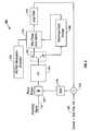
- FIG. 1is a block diagram of an orthogonal frequency division multiplexed (OFDM) receiver illustrating a phase noise contribution of the local oscillators (LO) of the radio portion of the OFDM receiver, and in which one or more embodiments of the invention may be practiced;
- OFDMorthogonal frequency division multiplexed
- FIG. 2is a diagram of the PHY-layer frame structure for the IEEE 802.11a standard used in OFDM communications, for example, by the OFDM receiver of FIG. 1;
- FIG. 3is a functional block diagram of a pilot tracking loop of a baseband processing portion of the OFDM receiver of FIG. 1, which utilizes a pilot phase error metric based on a maximum likelihood estimation approach for estimating the phase error of the OFDM data symbols in accordance with one embodiment of the invention;
- FIG. 4is a functional block diagram of a pilot phase error metric of the pilot tracking loop of FIG. 3 which is based upon maximum likelihood estimation in accordance with one embodiment of the invention
- FIG. 5is a graph illustrating the LO phase noise contribution vs. frequency using no pilot tracking and pilot tracking according to the embodiment of FIGS. 3 and 4;
- FIG. 6is a flowchart of the steps performed in the pilot phase error metric of FIG. 4 in accordance with one embodiment of the invention.
- FIG. 7is an illustration of the closed-loop transfer functions of the pilot tracking loop of FIG. 3 according to one embodiment
- FIG. 8is a functional block diagram of a pilot tracking loop of the baseband processing portion of the OFDM receiver of FIG. 1, which includes a phase error metric utilizing a maximum likelihood estimator for the phase error of OFDM data symbols in accordance with another embodiment of the invention;
- FIG. 9is a functional block diagram of the pilot phase error metric of the pilot tracking loop of FIG. 8 using an optimum maximum likelihood estimation performed in accordance with one embodiment of the invention.
- FIG. 10is a functional block diagram of a discrete Fourier transform portion of the pilot phase error metric of FIG. 9 in accordance with yet another embodiment of the invention.
- FIG. 11is an illustration of the closed-loop transfer functions of the pilot tracking loop 806 of FIG. 8 according to another embodiment
- FIG. 12is a graph illustrating the LO phase noise contribution vs. frequency using no pilot tracking, pilot tracking according to the embodiment of FIGS. 3 through 4 and pilot tracking according to the embodiments of FIGS. 8 through 10;
- FIG. 13is a functional block diagram illustrating the loop filter of the pilot tracking loop of FIG. 8 according to one embodiment of the invention.
- FIG. 14is a functional block diagram of a digital implementation of the loop filter of FIG. 13 according to another embodiment of the invention.
- FIG. 15is a functional block diagram illustrating a simulated version of the digital loop filter of FIG. 14;
- FIG. 16is a graph illustrating the response of the simulated tracking loop filter of FIG. 15 as measured at the indicated probe points in FIG. 15;
- FIG. 17is a flowchart is shown of the steps performed to reduce the effects of frequency pulling and frequency pushing according to another embodiment of the invention.
- FIG. 1a block diagram is shown of an orthogonal frequency division multiplexed (OFDM) receiver illustrating the phase noise contribution of the local oscillators (LO) of the radio portion of the OFDM receiver, and in which one or more embodiments of the invention may be practiced.
- the OFDM receiver 100(also referred to as the receiver 100 ) includes an antenna 102 , a radio portion 104 and a baseband processing portion 106 .
- the radio portion 104includes local oscillators, shown collectively as local oscillator 108 (hereinafter referred to as LO 108 ), which introduces phase noise, shown as noise 110 , into the receiver 100 .
- LO 108local oscillator
- the noise 110is summed with the signals from the local oscillator 108 (illustrated at summer 114 ) and multiplied with the received signal at mixer 112 .
- the received signalis converted from RF (radio frequency) to an incoming signal 116 (also referred to as a “baseband/IF signal”) sent to the baseband processing portion 106 .
- the incoming signal 116may be a baseband signal (also referred to as a “baseband I/Q signal”).
- the incoming signal 116may be an intermediate frequency signal (also referred to as an IF signal) which is converted to baseband in the baseband processing portion 106 .
- the frequency translation from RF to basebandcan be done in multiple steps of frequency conversions.
- the incoming signal 116includes phase noise 110 as introduced by the LO 108 of the radio portion 104 of the OFDM receiver 100 .
- the incoming signal 116will also include phase noise as introduced by the local oscillators at the OFDM transmitter that transmits the OFDM signal to the receiver 100 as well as other noise introduced by the channel, e.g., changes in the multipath, movements of the receiver and transmitter relative to each other, and thermal noise.
- One solution to reducing the phase noise contribution of the LO 108is to design a radio portion 104 having good phase noise performance characteristics.
- the radio portion 104 and the baseband processing portion 106are integrated into one or more devices (i.e., chips)
- the design of such a radio portion 104is difficult and costly, particularly as higher order modulations are used.
- the specifications of the radio portion 104are relaxed such that a certain amount of phase noise 110 introduced by the LO 108 is acceptable.
- the phase noise 110 introduced by the LO 108is compensated for by the baseband processing portion 106 of the OFDM receiver 100 .
- the baseband processing portion 106works to effectively relax the phase noise performance requirements of the radio portion 104 , which allows the radio portion 104 to be designed anticipating the poorer phase noise performance.
- the radio portion 104can be implemented more easily and inexpensively.
- the key to such embodimentsis understanding the relationship between both the radio portion 104 and the baseband processing portion 106 .
- a typical approachmight be to optimally design the radio portion 104 and then optimally design the baseband processing portion 106 .
- Such an approachleads to a complex and expensive radio portion 104 requiring good phase noise performance. That is, the phase noise introduced by the LO 108 does not need to be further corrected and is sufficient to support signaling at the specified modulations.
- the modulation constellationincreases, for example, moving from 16-QAM to 64-QAM to 256-QAM, less and less phase noise introduced by the LO 108 can be tolerated. Otherwise, with such higher-order constellations, the same phase noise introduced by the LO 108 is more likely to result in constellation points being confused.
- the specifications of the radio portion 104become increasingly more stringent.
- a radio portion 104 with good phase noise performancebecomes more difficult and expensive to implement as the constellation complexity increases.
- the radio portion 104by relaxing the requirements of the radio portion 104 such that the radio portion 104 contributes phase noise 110 that might otherwise result in constellation point errors (possibly resulting in an unacceptable symbol error rate), a simpler and less expensive radio portion is implemented. Furthermore, advantageously the phase noise contribution of the LO 108 is tracked and removed using a pilot tracking loop employing a maximum likelihood estimator in the baseband processing portion 106 of the receiver 100 . Thus, the baseband processing portion 106 effectively reduces the phase noise contribution of the LO 108 of the radio portion 104 without requiring that the radio portion 104 have good phase noise performance.
- the baseband processing portion 106 and the radio portion 104are designed together to provide an integrated OFDM receiver 100 that is more easily implementable on a single device and that can support many symbol by symbol modulations, such as MPSK or M-ary QAM, e.g., constellations of 64-QAM or higher.
- FIG. 2a diagram is shown of the PHY-layer frame structure for the 802.11a standard used in OFDM communications, for example, by the OFDM receiver 100 of FIG. 1 .
- the preamble 202includes a short symbol portion 206 including 10 short symbols (t 1 -t 10 ) and a long symbol portion 208 including two long symbols (T 1 and T 2 ).
- the data portion 204includes multiple data symbols 210 (also referred to as OFDM symbols or simply symbols). Each long symbol T 1 and T 2 and each data symbol 210 having a guard time interval 212 preceding it.
- the frame 200is also referred to as a PHY-layer frame or a medium access control (MAC) frame.
- MACmedium access control
- the preamble 202is chosen which is well suited to measuring frequency errors quickly in the communication system, but is substantially less ideal for measuring precision time of signal arrival.
- the short symbol portion 206is used for signal detection, diversity selection, coarse frequency offset estimation, and timing synchronization.
- the long symbol portion 208is used for channel estimation and fine frequency offset estimation.
- each OFDM symbol 210consists of a properly time-windowed set of modulated subcarriers (e.g., sine waves) and a guard time interval 212 .
- this guard time interval 212is utilized to allow the communication channel's transient to decay before transmitting the next OFDM symbol 210 .
- this guard time interval 212is 0.8 ⁇ s and the symbol 210 length is 3.2 ⁇ s.
- the guard time interval in the long symbol portion 208is twice the duration of that preceding each data symbol 210 , i.e., 1.6 ⁇ s.
- the guard time interval 212is selectable between 0.4 ⁇ s or 0.8 ⁇ s while the symbol 210 length is 3.2 ⁇ s. As such, the guard time interval 212 is long enough such that all reflections of the transmitted symbol 210 are adequately reduced prior to transmission of the next OFDM symbol 210 .
- each symbolwhether the data symbol 210 or one of the long symbols T 1 and T 2 , includes 48 data bearing subcarriers and a plurality of pilot subcarriers (also referred to as “pilot tones” or simply as “pilots”) buried within the signal that do not transport data, e.g., 4 pilots in the IEEE 802.11a and HiperLAN2 waveforms.
- pilotsoccupy subcarrier positions ⁇ 7 ⁇ F and ⁇ 21 ⁇ F of each symbol.
- the phase behavior of the pilotsis precisely known aside from channel related impairments and LO phase noise.
- phase noise imposed on these pilot tonesis the same phase noise that is imposed upon all of the subcarriers, it is possible to mitigate much of the LO phase noise by phase tracking these pilots.
- SNRsignal-to-noise ratio
- the effective noise bandwidth of the tracking algorithmcan not be made arbitrarily large. Rather, the bandwidth of the tracking algorithm is based upon a compromise between LO-related phase noise suppression and additive noise due to the finite input SNR.
- a pilot phase error metric of a pilot tracking loopprocesses complex signal measurements for all of the pilots of each subsequent data symbol 210 along with the pilot reference points to produce an estimate of the aggregate phase error of the current OFDM data symbol as compared to the actual phase at the beginning of the MAC frame 200 .
- the pilot phase error metricis based on a maximum likelihood estimation approach in how the complex signal measurements of the pilots and the pilot reference points are combined.
- this embodimentestimates the aggregate phase error of the data symbol without having to explicitly calculate the amplitude and phase of the individual pilots in the long symbol portion 208 or calculate the amplitude and phase of the individual pilots of each data symbol 210 .
- the estimation of the aggregate phase error of the current data symbolis then fed back through a loop filter and used to rotate the phase of the incoming baseband IQ signal for the next OFDM data symbols so that they will be received with an improved phase error.
- This maximum likelihood estimation-based approach in the pilot phase error metricis a departure from conventional methods in that it tracks the pilot aggregate of the data symbols, rather than only tracking the strongest of the plurality of pilots of the data symbols.
- the maximum likelihood pilot phase error metriccompensates for the poor phase noise performance of the radio portion of the OFDM receiver.
- a natural by-product of the maximum likelihood metricis that it also maximizes the effective SNR for the pilot symbols considered as a whole.
- the additional SNRpermits greater suppression of the LO phase noise by these disclosed techniques.
- the maximum likelihood formulationautomatically adjust the effective contribution made by each pilot even in the presence of frequency selective fading, delivering the lowest variance phase error estimate possible.
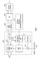
- FIG. 3a functional block diagram is shown of a pilot tracking loop 300 of the baseband processing portion of the OFDM receiver of FIG. 1, which utilizes a pilot phase error metric based on a maximum likelihood estimation approach for estimating the phase error of OFDM data symbols in accordance with one embodiment of the invention.
- a PN pilot modulation generator 312pseudo random pilot modulation generator
- the incoming signal 116is input to the phase rotator 302 .
- the phase rotator 302is coupled to the FFT 304 , which is coupled to the switch 306 .
- the switch 306is coupled to the pilot reference storage 308 , which is coupled to the pilot phase error metric 310 .
- the switch 306is directly coupled to the pilot phase error metric 310 .
- the PN pilot modulation generator 312is also coupled to the pilot phase error metric 310 .
- the loop filter 314couples the pilot phase error metric 310 to the NCO 316 via the summation 318 and the NCO 316 is coupled back to the phase rotator 302 .
- the summation 318sums the output of the loop filter 314 with the coarse and fine frequency estimate signal 320 , which is then output to the NCO 316 .
- the pilot tracking loop 300(also referred to as a phase-locked loop) is used to track the phase changes of all of the plurality of pilots for each symbol in order to correct or minimize the phase error for subsequent data symbols relative to the reference points measured, for example, during the preamble.
- the pilot tracking loopdetermines reference points for each of the respective pilots since the amplitudes and phases of the received pilots are completely unknown and may vary from pilot to pilot within each symbol due to the multipath and the time of arrival.
- the pilots of the long symbols T 1 and T 2 of the OFDM preamble waveformare used to determine the reference points.
- the switch 306when the long symbols of the incoming signal 116 pass through the phase rotator 302 , they are unchanged in phase since the pilot tracking loop is not yet activated, i.e., the switch 306 is in position A.
- a channel estimateis made by the FFT 304 and saved, e.g., the complex signal measurements I+jQ for each pilot are extracted at the FFT 304 and saved in the reference point storage 308 .
- the NCO 316is preset to the proper initial conditions and the loop filter 314 updating is disabled.
- the subsequent data symbols of the incoming signal 116are processed by the FFT 304 one at a time.
- the switch 306is now moved to position B, which activates the pilot tracking loop.
- the outputs of the FFT 304i.e., complex signal measurements, corresponding to each of the pilots of the current data symbol are input to the pilot phase error metric 310 which is based upon a maximum likelihood estimation approach using each of the pilots of the data symbol as compared to the respective stored reference points u k and v k for each pilot.
- the result of the pilot phase error metric 310is an aggregate phase error estimate over the respective data symbol.
- the pilot phase error metric 310advantageously uses all of the pilots to produce its estimate. It is important that all of the pilots of each data symbol are tracked in order to mitigate the effect of frequency selective fading over the frequency range of the OFDM data symbol.
- the loop filter 314is updated based upon the output of the pilot phase error metric 310 . Since the pilot phase error metric 310 and the loop filter 314 track relatively small frequencies, the coarse/fine frequency estimate signal 320 (obtained from the channel estimation process during the long symbols of the preamble at another portion of the OFDM receiver) is summed with the output of the loop filter 314 at summation 318 . Thus, the loop filter 314 then modifies the NCO 316 which causes the phase rotator 302 to de-rotate the incoming signal 116 to keep the aggregate phase error as low as possible.
- the loop filter 314 , summation 318 and the NCO 316are well known components that may be found in many phase-locked loops as known in the art.
- the PN pilot modulation generator 312provides the pseudo random number sequence to remove the random BPSK (binary phase shift keying) modulation applied to each of the pilot tones as given in the IEEE 802.11a standard.
- the pilot tracking loop 300includes phase rotator 302 for receiving and phase de-rotating the incoming signal 116 , the switch 306 , the reference point storage 308 , the pilot phase error metric 310 , the loop filter 314 , and the NCO 316 while advantageously utilizing the FFT 304 which is required within the OFDM receiver. It is also noted that in this embodiment, the phase rotator 302 is provided before the FFT 304 in the receiver such that the phase error is corrected prior to the FFT 304 operation. In the event the incoming signal 116 comprises an IF signal, the phase rotator also converts this IF signal to a baseband signal or a baseband I/Q signal. Thus, whether the incoming signal 116 is a baseband signal or an IF signal, the output of the phase rotator is a baseband signal.
- FIG. 4a functional block diagram is shown of the pilot phase error metric of the pilot tracking loop of FIG. 3 which is based upon maximum likelihood estimation in accordance with one embodiment of the invention.
- the pilot phase error metric 310including multiplexers 402 and 404 , a maximum likelihood phase error/weighting processor 406 , a quality estimator 408 , a phase error estimator 410 , and a random pilot modulation removal 412 .
- the PN pilot modulation generator 312 and the reference point storage 308which includes a u k storage 414 and a v k storage 416 .
- Input I and Q samples from the FFT 304 for the respective pilots of the OFDM data symbolsare illustrated as signals 418 and 420 for pilot #0, signals 422 and 424 for pilot #1, signals 426 and 428 for pilot #2, and signals 430 and 432 for pilot #3.
- u k and v kare complex signal measurements in rectangular form for each pilot that represent the reference points in IQ space for each of the four pilots (i.e., pilot #0, pilot #1, pilot #2 and pilot #3). These pilot reference points are saved for use in the maximum likelihood phase error/weighting processor 406 .
- r k (t)is the received signal
- s k (t)is the transmitted signal
- n k (t)represents complex Gaussian noise having a two-sided power spectral density of N o /2 W/Hz.
- the pilot phase tracking loopis activated, e.g., the switch 306 of FIG. 3 is moved to position B.
- each r k (t)changes with time from data symbol to data symbol over the frame structure.
- the sampled tracking looptracks the nominal pilot subcarrier phase departure from the phase of the reference point at the beginning of the frame structure for each pilot.
- the pilot tracking loopis activated and the complex signal measurements (Is and Qs) from the FFT corresponding to each of the respective pilots #0 through #3 for each subsequent data symbol are coupled to the respective one of multiplexers 402 and 404 to be input into the maximum likelihood phase error/weighting processor 406 .
- the pilot reference pointsare stored in rectangular form as u k and v k and that the amplitude and phase of each of the pilot reference points is not actually calculated.
- the subsequent data symbol by data symbol complex signal measurements of the in-phase and quadrature terms for the same pilot tones during the rest of the burst receptionare labeled as I k,m and Q k,m , where m is the data symbol time index.
- the I k,m values from the FFT operation for each data symbolare coupled to multiplexer 402 while the Q k,m values from the FFT operation for each data symbol are coupled to multiplexer 404 .
- the multiplexers 402 and 404function to buffer the I k,m and Q k,m values to the maximum likelihood phase error/weighting processor 406 .
- the maximum likelihood phase error/weighting processor 406serially processes one set of I k,m and Q k,m values at a time such that redundant gates are not required to simultaneously perform the steps in the maximum likelihood phase error/weighting processor 406 in parallel.
- rm k (t)represents the k th pilot after removal of the phase initial estimate for the particular pilot during the long symbol portion of the preamble.
- ⁇ eis the actual pilot phase error of the k th pilot of the data symbol relative to the pilot reference point, which is not explicitly calculated, but is assumed to be the same for all of the pilots of a given data symbol.
- the MAC frame time durationis purposely chosen such that the channel characteristics change very little over an individual MAC frame. Therefore, for a specific MAC frame, it is assumed that
- A k′ a constant.
- the pilot tracking loop of this embodimentprimarily tracks phase rather than signal amplitude, some error in signal amplitude is acceptable.
- n kc and n ksare the real and imaginary parts of the k th bin noise sample n k and ⁇ is the standard deviation of the Gaussian noise.
- ⁇ circumflex over ( ⁇ ) ⁇is the estimate of the aggregate pilot phase error of a data symbol relative to the reference points looking at all of the pilots of the data symbol together.
- rm k,m( I k , m + jQ k , m ) ⁇ ( u k - jv k u k 2 + v k 2 ) Eq . ⁇ ( 9 )
- rm k,mrepresents the signal measurement of the k th pilot after removal of the phase initial estimate, which is not explicitly calculated.
- each pilot signal contribution of Eq. (9)is then weighted by the signal amplitude A k of the k th pilot.
- the amplitudes A kare time varying, they generally do not vary over the duration of the MAC frame such that A k (t) approximates the A k measurement at the beginning of the MAC frame, e.g., from the reference points u k +jv k of the long symbol duration.
- Eq. (13)must be adjusted to deal with the random bi-phase modulation of the pilot subcarriers during the frame; however, the quantity in Eq. (13) is the estimate that is produced by the pilot phase error metric, and is further shown in more detail below as Eq. (14).
- the argument of the complex composite signal(i.e., Eq. (13)) is determined by the phase error estimator 410 and is based upon the maximum likelihood estimation approach of Eq. (6), which is re-written below in Eqs. (14) through (16).
- Eq. (13)the argument of the complex composite signal
- Eq. (14)the output of the phase error estimator 410 is given by Eq. (14).
- Eq. (14)making use of the small angle approximation within the phase error estimator 410 , Eq. (14) can be recast as Eqs.
- the maximum likelihood/weighting processor 406calculates the quantities in the numerator and the denominator of Eqs. (14) through (16) while the quantity ⁇ circumflex over ( ⁇ ) ⁇ m of Eqs. (14) through (16) is determined in the phase error estimator 410 .
- the quantities in the numerator and the denominator or Eqs. (14) through (16)are weighted averages producing composite I and Q signals that represent the deviation of the pilots of the current data symbol compared to the reference points measured at the beginning of the frame.
- the random bi-phase modulation applied to the pilots at the OFDM transmitteris removed by the random pilot modulation removal 412 , which uses a pseudo random sequence which is known a priori from the PN pilot modulation generator 312 .
- the output of the random pilot modulation removal 412is the aggregate phase error of the processed data symbol, ⁇ circumflex over ( ⁇ ) ⁇ m .
- the multiplexers 402 and 404buffer the I and Q samples for each pilot of the symbol received from the FFT operation.
- the maximum likelihood phase error/weighting processor 406calculates the numerator and denominator of Eqs. (14) through (16), it only processes one pilot at a time. This reduces the overall gate count in a design implemented in a chip.
- redundant gatesmay be used in place of the multiplexers 402 and 404 in other embodiments.
- all calculations done within the maximum likelihood phase error/weighting processor 406are done in rectangular form, instead of in polar form, for simplification reasons.
- the pilot phase error metric 310does not actually calculate the amplitude or phase of the individual pilot reference points, nor does it calculate the amplitude and phase of individual pilots of each subsequent data symbol. Likewise, the pilot phase error metric 310 does not actually calculate the relative phase error of individual pilots of each data symbol compared to each pilot reference point.
- the pilot phase error metric 310advantageously uses pre-signal detection combining techniques to combine the complex signal measurements (from the FFT operation) of the pilots to be used as the pilot reference points and the complex signal measurements of the pilots of each subsequent data symbol in such a way that a complex composite signal is generated prior to signal detection.
- This complex composite signalrepresents a weighted pilot phase error for the aggregate of the pilots of the m th data symbol relative to the pilot reference points.
- the maximum likelihood phase error/weighting processor 406determines the composite signals for the numerator and denominator of Eq. (14).
- the phase error estimator 410performs the signal detection by computing the arctangent in Eq. (14) to obtain the aggregate phase error for the m th data symbol.
- a processing gain of approximately 10log 10 n(where n is the number of pilots) is realized in comparison to performing signal detection on each individual pilot of the data symbol and then averaging them to obtain the aggregate phase error of the data symbol, e.g., approximately 6 dB in the 4 pilot case.
- pilot phase error metric 310performs pre-signal detection combining.
- the phase error estimator 410determines the phase angle of the aggregate phase error ⁇ circumflex over ( ⁇ ) ⁇ m or phase noise of the signaling, a potentially large portion of which is due to the phase noise contribution of the LO of the radio portion of the OFDM receiver.
- a preferred approachis to use a cordic-based arctangent method (see Eq. (14)) and an alternative approach is to use a small angle approximation (see Eq. (16)).
- the cordic-based arctangent approachdoes not require large bit-width multiplications. It only shifts and adds.
- the small angle approximationshould be faster than the cordic-based arctangent approach, but it involves large bit width multiplication or division and is more prone to difficulties with the numerical dynamic range.
- the cordic-based arctangent approachis implemented such that the cordic iteration is performed between 8 and 15 times.
- Cordic-based arctangent methodsare well known in the art, thus, no further explanation is required.
- the pilot phase error metric 310advantageously provides a maximum likelihood estimation based approach for the pilot phase error relative to the pilot reference points for all of the pilots of the OFDM symbols.
- the phasemay not change uniformly for all of the pilots as the channel conditions change.
- a single pilotmay have the strongest SNR (e.g., the highest amplitude) and its phase changes noticeably from symbol to symbol; however, the phase of the other pilots may remain unchanged, or have changed only slightly, from symbol to symbol. These other pilots may also continue to have a lower amplitude than the amplitude of the strongest pilot.
- the strongest pilotdoes not accurately reflect the phase characteristics of the entire OFDM data symbol.
- a more accurate picture of the signal phase across the OFDM symbolis estimated such that the phase contribution due to the multipath and also introduced by the LO of the OFDM radios can be minimized.
- M-ary QAMe.g., 64-QAM or 256-QAM
- several of the embodiments of the inventionwill reduce this phase error for many symbol by symbol modulations, such as MPSK and M-ary QAM.
- a natural by-product of the maximum likelihood metric of this embodimentis that it also maximizes the effective SNR for the pilot symbols considered as a whole.
- the additional SNRallows enhanced phase noise tracking resulting in greater suppression of the LO phase noise.
- the quality estimator 408calculates a measure of the pilot tracking loop's quality, which is required elsewhere in the signal processing of the OFDM receiver.
- the quality estimator 408may be integrated with the maximum likelihood phase error/weighting processor 406 .
- FIG. 5a graph is shown illustrating the LO phase noise contribution vs. frequency offset in Hz using no pilot tracking and pilot tracking according to the embodiment of FIGS. 3 and 4.
- Line 502represents the LO phase contribution spectrum without pilot tracking techniques synthesized at 4 GHz.
- the graph of FIG. 5does not include channel additive Gaussian noise.
- the achievable phase noise performance in a free running on-chip VCOmay be approximately ⁇ 78 dBc/Hz at 10 kHz offset.
- the integrated phase noise interfering with each subcarrieris on the order of 2.7 degrees rms, which is excessive for 64-QAM and above.
- the achievable phase noise performance in a free running on-chip VCOis greater than about ⁇ 80 dBc/Hz at 10 kHz offset. Also, in one embodiment, it is noted that phase noise is present in both the transmitter and receiver ends and that above about 1.5 degrees rms, the integrated phase noise interfering with each subcarrier at the receiver end becomes excessive for 64-QAM communications.
- Line 504represents the phase noise contribution spectrum of the LO of the radio portion with the pilot phase tracking of the embodiments described above, such that the phase noise contribution is significantly reduced, particular at lower frequency offsets.
- the integrated phase error interfering with each subcarriercan be substantially improved, the actual amount being a function of the signal constellation type and the prevailing channel SNR.
- the pilot reference pointsare determined for each pilot subcarrier of the OFDM waveform (Step 602 ).
- These reference points u k and v kare the complex reference points within IQ space which represent the respective pilots and are determined, in one embodiment, by taking the output of the FFT operation for each of the pilots of the long symbol portion of the preamble of the IEEE 802.11a waveform.
- these pilot reference pointsare received into the pilot phase error metric 310 of FIG. 3 . This is performed when the pilot tracking loop of FIG. 3 is not activated, for example, the switch 306 of FIG. 3 is in position A.
- these reference pointsare saved (Step 604 ), for example, in the reference point storage of FIGS. 3 and 4.
- the pilot reference pointsmay be obtained by taking the output of the FFT operation for each of the pilots of a particular data symbol (e.g., data portion 204 of FIG. 2) within the data symbol portion of the MAC frame (e.g., data portion 204 of FIG. 2 ), rather than from the long symbol portion of the preamble.
- the length of the data portionmay be significantly longer in duration than that specified in the IEEE 802.11a standard and may require new pilot reference points to be obtained from within the data portion. For example, in such cases, the phase of the data symbols in the middle or near the end of the data portion may be quite different relative to the pilot reference points measured during the preamble.
- pilot reference pointsmay be obtained using pilots of symbols from the preamble or from pilot from symbols in the data portion of a MAC frame.
- the pilot tracking loopis activated (e.g., switch 306 of FIG. 3 is now in position B).
- complex signal measurementsare determined in the FFT operation for each of the plurality of pilots for a subsequent data symbol, or more generically, a subsequent symbol (Step 606 ).
- these complex signal measurementsare received at the pilot phase error metric of FIG. 3 . This is done by taking the outputs of the frequency bins of the FFT operation corresponding to the respective pilot subcarriers.
- the pilot phase error metricperforms pre-detection combining and computes a complex signal for each pilot of the subsequent data symbol based upon the pilot reference points and the complex signal measurements for the pilots of the subsequent data symbol (Step 608 ).
- the complex signal for each pilot of the subsequent data symbolis given by Eq. (11).
- the complex signalsare summed to produce a complex composite signal (Step 610 ).
- the complex composite signal for the subsequent data symbolis represented in Eq. (12). It is noted that the pilot phase error metric deals strictly with vectors and thus, no phase is actually determined at this point, i.e., signal detection has not yet occurred.
- Step 612the aggregate pilot phase error for the subsequent data symbol is estimated (Step 612 ).
- This estimateis obtained by determining the argument of the complex composite signal, for example, as given in Eq. (13).
- the argument of the complex composite signalis determined as guided by Eq. (6) in the phase error estimator 410 of FIG. 4 and may be done using a cordic-based arctangent approach (see Eq. (14)) or a small angle approximation approach (see Eqs. (15) and (16)).
- signal detectionoccurs during Step 612 , for example, in the arctangent operation.
- Steps 602 through 612apply a pilot phase error metric based on a maximum likelihood-based estimation that advantageously tracks all of the pilots for each data symbol of the OFDM waveform.
- this estimatemust be modified to remove the pseudo random modulation present on the pilots. For example, this is removed at the random pilot modulation removal 412 of FIG. 4, which uses the PN pilot modulation generator 312 .
- Step 614the estimate of the aggregate phase error is used to modify the pilot tracking loop and then Steps 606 through 614 are repeated until the end of the MAC frame (Step 614 ). This is done by the updating the loop filter 314 of FIG. 3, which adjusts the NCO 316 of FIG. 3 .
- the NCO 316causes the phase rotator 302 of FIG. 3 to de-rotate the incoming baseband signal 116 to minimize the phase error of the next symbols, e.g., the next data symbols.
- Steps 606 through 614are repeated for the next OFDM data symbol (or more generally, the next OFDM symbol) in an iterative fashion.
- Steps 602 , 606 , 608 and 610are performed by the maximum likelihood phase error/weighting processor 406 of FIG. 4 .
- Step 612is performed by the phase error estimator 410 of FIG. 4 .
- all of the calculations of the maximum likelihood phase error/weighting processor 406are carried out in rectangular form to simplify the implementation.
- the steps of FIG. 6are typically performed as a set of instructions that are performed in dedicated hardware for optimum speed in the calculations or in software using a processor or other machine to execute the instructions to accomplish the given steps.
- the steps of FIG. 6are performed by the pilot tracking loop of the baseband processing portion of an OFDM receiver having a pilot phase error metric and utilizing the FFT operation of the OFDM receiver.
- the baseband processing portion and the radio portion of the OFDM receivermay be integrated on to one or more devices or chips.
- the FFT 304must wait to receive all of the samples of a given data symbol before it begins processing them. Then, the FFT 304 processes the samples in order to produce the complex signal measurements that are input to the pilot phase error metric 310 . Then, the pilot phase error metric 310 processes these complex signal measurements as described with reference to FIGS. 4-6. Once an estimate of the aggregate phase error is obtained, the loop filter 314 is updated which causes the NCO 316 to make adjustments to the phase rotator 302 to minimize the phase error for subsequent data symbols.
- the total processing delay in the FFT 304 and the pilot phase error metric 310is about another 3 ⁇ sec. This overall delay of about 6 ⁇ sec negatively impacts the maximum allowable closed-loop bandwidth of the pilot tracking loop 300 .
- This choicealso corresponds to the maximum closed-loop bandwidth achievable in the sampled control pilot tracking loop.
- the maximum closed-loop bandwidthis approximately 40 kHz for the 250 kHz OFDM symbol rate (of the IEEE 802.11a and HyperLAN2 standards). While this tracking loop bandwidth is sufficient to track and reduce local oscillator phase noise at small frequency offsets, it is too small to help reduce local oscillator phase noise at larger frequency offsets, for example, frequency offsets in the 100 kHz range, as is illustrated in FIG. 7 below.
- FIG. 7an illustration is shown of the closed-loop transfer functions of the pilot tracking loop as shown in FIG. 3 .
- FIG. 8a functional block diagram is shown of a pilot tracking loop of the baseband processing portion of the OFDM receiver of FIG. 1, which includes a pilot phase error metric utilizing a maximum likelihood estimator for the phase error of OFDM data symbols in accordance with another embodiment of the invention. Shown are the incoming signal 116 , the phase rotator 302 , a baseband signal 810 which is ouput from the phase rotator 302 , a cyclic prefix removal 802 , the FFT 304 , and a channel estimator 804 .
- a pilot tracking loop 806which includes the phase rotator 302 , a pilot phase error metric 808 (also referred to as the phase error metric), the loop filter 314 , the summation 318 , the coarse and fine frequency estimate signal 320 and the NCO 316 . Also shown is the PN pilot modulation generator 312 .
- the incoming signal 116is input to the phase rotator 302 .
- the incoming signal 116may be a baseband signal or an IF signal.
- the output of the phase rotator 302i.e., the baseband signal 810 or baseband I/Q signal, is coupled to both the cyclic prefix removal 802 and the pilot phase error metric 808 .
- the output of the cyclic prefix removal 802is coupled to the FFT 304 , which is coupled to the channel estimator 804 . It is noted that in some embodiments, the cyclic prefix removal 802 occurs before the phase rotator 302 , such that the output of the phase rotator 302 is coupled directly to the FFT 304 .
- the cyclic prefix removal 802is an optional functional component illustrated in dashed lines. Furthermore, in some embodiments and as is known in the art, there may be other functional modules or processing operations that occur in between the phase rotator 302 and the FFT 304 in place of or in addition to the cyclic prefix removal 802 .
- the output of the pilot phase error metric 808is coupled to the loop filter 314 , which is coupled to the NCO 316 , which is coupled back to the phase rotator 302 . Since the pilot phase error metric 310 and the loop filter 314 track relatively small frequencies, the output of the loop filter 314 is summed at summation 318 with the coarse and fine frequency estimate signal 320 .
- the coarse and fine frequency estimate signal 320is commonly derived at the channel estimator 804 .
- the pilot phase error metric 808is also coupled to the NCO 316 in order to preset the NCO 316 .
- the PN pilot modulation generator 312is coupled to the pilot phase error metric 808 .
- the pilot phase error metric 808rather than using the FFT 304 to process and produce the complex signal measurements needed for the pilot phase error metric, the pilot phase error metric 808 generates the complex signal measurements itself. This reduces the processing delay that occurs while waiting for the FFT operation to be completed, which will increase the allowable closed-loop bandwidth.
- the FFT 304is still part of the OFDM baseband processing portion of the OFDM receiver.
- the incoming signal 116passes through the phase rotator 302 .
- the output of the phase rotator 302goes through the cyclic prefix removal 802 prior to entering the FFT 304 .
- the cyclic prefix removal 802removes the guard time interval prepended to each OFDM symbol.
- the output of the phase rotator 302may be directly routed to the FFT 304 , the cyclic prefix removal occurring elsewhere.
- the FFT 304continues to process the baseband IQ signal.
- the channel estimator 804utilizes the outputs of the FFT 304 to determine the initial course frequency estimate from short symbols (e.g., t 1 through t 10 ) of the OFDM preamble and the fine frequency estimate from the long symbols (e.g., T 1 and T 2 ) of the OFDM preamble. This information is used to generate the coarse and fine frequency estimate signal 320 needed in the pilot tracking loop 806 .
- the output of the phase rotatori.e., the baseband signal 810
- the FFT 304e.g., through the cyclic prefix removal 802
- the pilot phase error metric 808 of the pilot tracking loop 806in parallel paths, i.e., path A and path B.
- This embodiment of the pilot tracking loop 806is a departure from those known in the art.
- the fact that the incoming signal 116 is phase de-rotated prior to the FFT operationis unique. Most pilot tracking techniques take place and adjust the phase after the FFT operation.
- processing the baseband signal 810 in parallel paths, shown as path A and path B, with the FFT 304is unique.
- pilot trackingif present occurs after the completion of the FFT operation, not in a parallel path to the FFT operation.
- path B for pilot trackingis not known in the existing art.
- all pilot trackingoccurs before the FFT 304 operation, such that the phase error for subsequent symbols, e.g., subsequent data symbols, is reduced prior to these subsequent OFDM data symbols being processed by the FFT 304 .
- the output of the phase rotator 302is routed to the pilot phase error metric 808 , which outputs an estimate of the aggregate phase error over the entire OFDM data symbol. This estimate is used to update the loop filter 314 , which triggers the NCO 316 to rotate the phase of the incoming signal 116 for subsequent OFDM symbols.
- the pilot phase error metric 808is similar to the pilot phase error metric 310 of FIG. 3, but includes respective discrete Fourier transforms (DFTs) to generate complex signal measurements corresponding to each of the respective pilot subcarriers of the OFDM symbols. See FIG. 9 for more details on the pilot phase error metric 808 .
- the pilot phase error metric 808 of FIG. 8determines its own pilot reference points (u k and v k ) and saves them. Then the pilot phase error metric 808 determines complex signal measurements (I k,m and Q k,m ) corresponding to each of the pilot subcarriers of subsequent symbols and processes them as the pilot phase error metric 310 of FIG. 3 .
- the pilot phase error metric 808may generate an aggregate phase error almost immediately after receiving the last time sample of the baseband signal 810 for a given symbol. This reduces the time delay within the pilot tracking loop, which will increase the allowable closed-loop bandwidth.
- the FFT 304 of FIGS. 3 and 8waits until it receives all of the samples of the given OFDM symbol, e.g., given OFDM data symbol, to begin processing them.
- FIG. 9a functional block diagram is shown of the pilot phase error metric of the pilot tracking loop of FIG. 8 using a maximum likelihood estimation performed in accordance with one embodiment of the invention.
- the pilot phase error metric 808including a discrete Fourier transform portion 901 (hereinafter referred to as DFT portion 901 ), multiplexers 402 and 404 , a maximum likelihood phase error/weighting processor 406 , a quality estimator 408 , a phase error estimator 410 , and a random pilot modulation removal 412 .
- the DFT portion 901includes DFTs 902 , 904 , 906 and 908 (each of which may be referred to generically as Fourier transforms).
- the PN pilot modulation generator 312 and the reference point storage 308which includes a u k storage 414 and a v k storage 416 .
- the pilot phase error metric 808 of FIG. 9works similarly to the pilot phase error metric 310 of FIG. 4 .
- these valuesare determined in the DFT portion 901 by respective ones of DFTs 902 , 904 , 906 and 908 .
- Each of these DFTsis configured to process the respective pilots of the OFDM waveform.
- DFT 902determines the complex signal measurements in rectangular form for pilot #0 (i.e., DFT 902 determines u 0 and v 0 ), DFT 904 determines the complex signal measurements in rectangular form for pilot #1 (i.e., DFT 904 determines u 1 and v 1 ), DFT 906 determines the complex signal measurements in rectangular form for pilot #2 (i.e., DFT 906 determines u 2 and v 2 ), and DFT 908 determines the complex signal measurements in rectangular form for pilot #3 (i.e., DFT 908 determines u 3 and v 3 ).
- pilot #0i.e., DFT 902 determines u 0 and v 0
- DFT 904determines the complex signal measurements in rectangular form for pilot #1 (i.e., DFT 904 determines u 1 and v 1 )
- DFT 906determines the complex signal measurements in rectangular form for pilot #2 (i.e., DFT 906 determines u 2 and v 2
- u k and v kare stored in the reference point storage 308 , i.e., in the u k storage 414 and a v k storage 416 . It is noted that the reference point storage 308 is not shown in FIG. 8 . This reference point storage 308 may be embodied within the pilot phase error metric 808 or separately, as shown, such that the reference point storage 308 couples to the pilot phase error metric 808 . With respect to Step 602 of FIG. 6, respective ones of DFTs 902 , 904 , 906 and 908 , not the FFT operation of the OFDM receiver, determine the pilot reference points for each of a plurality of k pilots. As described with reference to FIG. 4, these pilot reference points are saved for use in the maximum likelihood phase error/weighting processor 406 .
- the pilot tracking loop 806is activated.
- complex signal measurementsare determined by the DFT portion 901 using respective ones of DFTs 902 , 904 , 906 and 908 for each of the plurality of pilots for the subsequent symbols, e.g., subsequent data symbols, rather than using the FFT operation.
- the DFTs 902 , 904 , 906 and 908determine the complex signal measurements (I k,m and Q k,m ) corresponding to each of the pilot subcarriers of subsequent symbols.
- phase error metric 808also follows the same steps as recited in FIG. 6; however, Steps 602 and 606 are performed by the DFT portion 901 , instead of FFT 304 .
- the data portion of the MAC framemay be much longer in duration than that specified in IEEE 802.11a.
- the complex measurements obtained for the pilots of a particular OFDM data symbolare stored as pilot reference points, replacing the pilot reference points previously obtained during the preamble portion of the OFDM waveform.
- the pilot reference pointsmay be obtained from the pilots of an OFDM symbol, e.g., an OFDM data symbol, within the data portion of the MAC frame.
- the complex signal measurements of the pilots of subsequent OFDM symbols, e.g., subsequent OFDM data symbolsare compared to the pilot reference points obtained from within the data portion of the MAC frame.
- the pilot phase error metric 808since the pilot phase error metric 808 does not have to wait for the FFT 304 operation to be complete, the pilot phase error metric 808 generates an aggregate phase error almost immediately after receiving the last time sample of the baseband IQ signal output from the phase rotator 302 for a given symbol. This reduces the time delay within the pilot tracking loop, which will increase the allowable closed-loop bandwidth. In contrast, the FFT 304 of FIGS. 3 and 8 waits until it receives all of the samples of the given OFDM data symbol to begin processing them.
- the time delay from the arrival of the last input sample pair (I,Q) of the current OFDM symbol into the pilot phase error metric 808 to the computation of the output of the phase error metric 808 , ⁇ circumflex over ( ⁇ ) ⁇ m ,should be less than or equal to 10 clocks at 40 MHz.
- the total transport delay through the pilot phase error metric 808should be kept to less than 10% of an OFDM symbol, i.e., about 0.40 ⁇ sec.
- thisrepresents a significant savings in time as compared to using the output bins of the FFT as described with reference to FIGS. 3-5.
- the pilot phase error metric 808 of FIG. 8 and the pilot phase error metric 310 of FIG. 3may employ other metrics to track the phase error of the OFDM data symbols. For example, rather than determining an aggregate phase error estimate of the current OFDM data symbol relative to the pilot reference points for each of the pilots of the preamble or for each of the pilots of a data symbol within the data portion of the MAC frame, a phase error estimate may be determined by tracking the pilots of the current OFDM data symbol relative to the strongest pilot of the preamble. Even such pilot phase error metrics when applied in the pilot tracking loops of FIGS. 3 and 8 are a departure from the known art since the phase rotation is applied to the incoming signal for subsequent OFDM data symbols prior to being input into the FFT operation of the OFDM receiver.
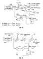
- FIG. 10a functional block diagram is shown of one embodiment of the DFT portion 901 of the phase error metric of FIG. 9 . Illustrated is the DFT portion 901 including the baseband signal 810 input into correlation processors 1002 and 1003 , sign reversal modules 1004 and 1005 , and integrate and dump modules 1006 and 1007 .
- the inphase (I) and quadrature (Q) terms of the baseband signal 810are correlated with the respective ones of the sine and cosine of the output of a numerically controlled oscillator 1010 at 7 ⁇ F (hereinafter referred to as NCO 1010 ) at multipliers 1012 , 1014 , 1016 , and 1018 .
- the outputs of multipliers 1012 and 1014are summed at summation 1020 , while the output of multiplier 1014 is subtracted from the output of multiplier 1012 at summation 1022 .
- the outputs of multipliers 1016 and 1018are summed at summation 1024 , while the output of multiplier 1016 is subtracted from the output of multiplier 1018 at summation 1026 .
- the inphase (I) and quadrature (Q) terms of the baseband signal 810are correlated with the respective ones of the sine and cosine of the output of a numerically controlled oscillator 1011 at 21 ⁇ F (hereinafter referred to as NCO 1011 ) at multipliers 1028 , 1030 , 1032 , and 1034 .
- the outputs of multipliers 1028 and 1030are summed at summation 1036 , while the output of multiplier 1030 is subtracted from the output of multiplier 1028 at summation 1038 .
- the outputs of multipliers 1032 and 1034are summed at summation 1040 , while the output of multiplier 1032 is subtracted from the output of multiplier 1034 at summation 1042 .
- the number of discrete DFTsis reduced from 4 to 2. That is, the number of NCOs and complex cross multiplies is reduced from 4 to 2 in the correlation processors 1002 and 1003 .
- the NCOs 1010 and 1011operate at 7 ⁇ F and 21 ⁇ F respectively and the negative frequencies are realized by using different signs in the addition processes (e.g., respective ones of summations 1020 , 1022 , 1024 , 1026 , 1036 , 1038 , 1040 and 1042 ) that immediately follow the multiplications (e.g., at respective ones of multipliers 1012 , 1014 , 1016 , 1018 , 1028 , 1030 , 1032 and 1034 ). Since these two frequencies (i.e., 7 ⁇ F and 21 ⁇ F) are known a priori, and they are tied to the symbol timing, the outputs of NCOs 1010 and 1011 are straightforward known number sequences.
- polarity differences between the pilot tones due to the random bi-phase modulation (e.g., BPSK) that is imposed on the OFDM pilot subcarriersare removed using respective ones of sign reversal multipliers 1044 , 1046 , 1048 , 1050 , 1052 , 1054 , 1056 and 1058 of the sign reversal modules 1004 and 1005 .
- sign reversal multipliers 1044 , 1046 , 1048 , 1050 , 1052 , 1054 , 1056 and 1058 of the sign reversal modules 1004 and 1005This is due to the fact that depending on various modes, the polarity of all the pilot tones is not necessarily +1. For example, the polarity of one or more pilot tones may be set to +1 while the polarity of others of the pilot tones may be set to ⁇ 1.
- the output of summations 1026 and 1020are multiplied at sign reversal multipliers 1044 and 1046 , respectively, by S 0 .
- the output of summations 1024 and 1022are multiplied at sign reversal multipliers 1048 and 1050 , respectively, by S 1 ;
- the output of summations 1042 and 1036are multiplied at sign reversal multipliers 1052 and 1064 , respectively, by S 2 ;
- the output of summations 1040 and 1038are multiplied at sign reversal multipliers 1056 and 1058 , respectively, by S 3 .
- the values of S 0 -S 3are either ⁇ 1 depending on the specific system design.
- the sign reversal modules 1004 and 1005are not needed. It is noted that the sign reversal modules 1004 and 1005 could occur either before the correlation processors 1002 and 1003 , or after the respective integrate and dump modules 1006 and 1007 ; however, the location was chosen in order to minimize the number of gates for implementation.
- the outputs of sign reversal modules 1004 and 1005are input to integrate and dump modules 1006 and 1007 .
- Each signalis input to a respective one integrators 1060 , which is then input to a respective one of shifters 1062 .
- the number of samples summed in the integrators 1060depends on whether the long symbols T 1 and T 2 of the long symbol portion 208 are being summed in the channel estimation (accumulating 2 ⁇ 3.2 ⁇ sec or 128 samples at 20 MHz (or 256 samples at 40 MHZ)). i.e., Ch Eat in FIG.
- the number of samples summed in the integrators 1060depends on whether the DFT portion 901 is determining the pilot reference points (Step 602 of FIG. 6) or whether the DFT portion 901 is determining the complex signal measurements for each of the pilots of a subsequent data symbol (Step 606 of FIG. 6 ). Additionally, the shifters 1062 dump a number of bits from 0 to 2 depending on the dock rate, the type of symbol (e.g., channel estimation symbol (Ch Est) or data symbol (Dat Sym)), and the type of constellation type or modulation.
- the type of symbole.g., channel estimation symbol (Ch Est) or data symbol (Dat Sym)
- the integrate and dump modules 1006 and 1007should be synchronized with the period of time recognized by the receiver as the active portion of the received OFDM symbol, and accumulation only occurs over this interval, e.g., a 3.2 ⁇ sec window.
- the accumulation windowshould be similarly aligned in time with the channel estimation process, precisely in-synch with the FFT channel estimation process that is occurring in parallel at the channel estimator 804 of FIG. 8 .
- the DFT portion 901outputs either the pilot reference points u k and v k or the complex signal measurements for the m th subsequent data symbol I k,m and Q k,m .
- themis a respective DFT bin output for each of the plurality of pilots of the OFDM waveform.
- These outputsare coupled to either the reference point storage 308 or one of multiplexers 402 and 404 as shown in FIG. 8 .
- the functionality and design of the correlation processors 1002 and 1003 , the sign reversal modules 1004 and 1005 and the integrate and dump modules 1006 and 1007 components of the DFT portion 901 of the phase error metric 808am well understood in the art. It is also noted that the DFT portion 901 represents one embodiment of the DFT portion 901 including DFTs 902 , 904 , 906 and 908 of FIG. 9 . It is further noted that one of ordinary skill in the art could easily modify the DFT portion 901 to achieve slightly different results depending on the implementation.
- FIG. 11an illustration is shown of the closed-loop transfer functions of the pilot tracking loop 806 of FIG. 8 .
- this illustrationdoes not include additive Gaussian noise. This choice also corresponds to the maximum closed-loop bandwidth achievable in the sampled control pilot tracking loop.
- the maximum usage closed-loop bandwidthis approximately 40 kHz for the 250 kHz OFDM symbol rate (of the IEEE 802.11a and HyperLAN2 standards) without the additional delay, in comparison to the maximum usable closed loop bandwidth of 15 kHz with the additional delay as shown in FIG. 7 .
- the maximum closed-loop bandwidthis derived from the symbol rate of 250 kHz divided by 2 ⁇ given an acceptable amount of delay.
- the pilot tracking loop 806 of FIG. 8is sufficient to track and reduce local oscillator phase noise at small frequency offsets, as well as at larger frequency offsets.
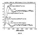
- FIG. 12a graph is shown illustrating the LO phase noise contribution vs. frequency using no pilot tracking, pilot tracking according to the embodiment of FIGS. 3 through 4 and pilot tracking according to the embodiments of FIGS. 8 through 10.
- Line 502represents the LO phase contribution spectrum without pilot tracking techniques synthesized at 4 GHz.
- the graphs of FIG. 5 and FIG. 12do not include channel additive Gaussian noise.
- the achievable phase noise performance in a free running on-chip VCOwill be approximately ⁇ 78 dBc/Hz at 10 kHz offset.
- the integrated phase noise interfering with each subcarrieris on the order of 2.7 degrees rms, which is excessive for 64-QAM and above.
- the achievable phase noise performance in a free running on-chip VCOis typically greater than about ⁇ 80 dBc/Hz at 10 kHz offset, which results in an integrated phase noise interfering with each subcarrier of greater than 2.5 degrees rms.
- Line 504represents the phase noise contribution spectrum of the LO of the radio portion with the pilot phase tracking of the embodiment of FIGS. 3 through 4 as described above, such that the phase noise contribution is significantly reduced, particular at lower frequency offsets. It is also seen that at higher frequency offsets, e.g., between 10 kHz and 100 kHz, the phase noise actually worsens in comparison to not using any pilot tracking techniques. It is also noted that as the closed loop tracking bandwidth is increased in the pilot tracking loop of FIGS. 3 and 4, more and more instability results due to additional delay added. Although not illustrated in FIG. 12, this results in an even more pronounced phase noise peaking at about 25-30 kHz in comparison to that shown in line 504 .
- Line 1202represents the phase noise contribution spectrum of the LO of the radio portion with the optimum pilot phase tracking of the embodiment of FIGS. 8 through 10 as described above, such that the phase noise contribution is also reduced, in comparison to no pilot tracking techniques and also in comparison to the phase noise contribution of the pilot phase tracking of FIGS. 3 through 4.
- the peaking shown in line 504is reduced at higher frequency offsets, more closely resembling line 502 at frequency offsets greater than about 11 kHz.
- the phase noise performance in a free running on-chip VCOwill be approximately ⁇ 85 dBc/Hz at a 10 kHz frequency offset.
- the integrated phase noiseis advantageously reduced from about 2.7 degrees rms to about 0.48 degrees rms using the pilot tracking loop of FIG. 8 .
- the integrated phase noisemay be reduced from greater than about 2.5 degrees rms to less than about 1 degree rms, and more preferably, less than 0.5 degrees rms.
- This improvement in the phase noisemakes it possible to reduce the requirements on the radio's LO phase noise performance.
- This improvementalso makes it possible to support higher order modulations, such as MPSK and M-ary QAM, e.g., QPSK, 16-QAM, 64-QAM, 128-QAM, or higher.
- FIG. 13a functional block diagram is shown illustrating the loop filter of the pilot tracking loop of FIG. 8 according to one embodiment of the invention. Illustrated are a signal decryption module 1302 , the incoming signal 116 (which is a baseband signal in this embodiment), an NCO/phase rotator 1304 outputting baseband signal 810 , the phase error metric 808 , the loop filter 314 , coarse/fine frequency estimate signal 320 and a summation 318 . Also shown are path A and path B for the baseband signal 810 .
- loop filter 314is illustrated for the embodiment of FIG. 8, these details of the loop filter also apply to the embodiment of FIG. 3 .
- the signal decryption module 1302is shown in FIG. 13, although not illustrated in FIG. 8 .
- the incoming signal 116 received into the NCO/phase rotator 1304has already been decrypted.
- the NCO and phase rotator functional blocks of FIG. 8are combined into the NCO/phase rotator module 1304 .
- the loop filter 314illustrated as a closed-loop tracking filter functions as a digital phase lock loop that tracks out small frequency errors remaining after the coarse and fine frequency estimation steps performed, for example, by the channel estimator 804 of FIG. 8 .
- the input to the loop filter 314is an estimate of the aggregate phase error of the processed data symbol relative to the average pilot phase of the pilot reference points, ⁇ circumflex over ( ⁇ ) ⁇ m .
- the loop filter 314 (and the NCO/phase rotator module 1304 )is clocked at sampling rates of 20 MHz or 40 MHz and the loop filter 314 outputs 20-bit words (19.07 Hz/lsb at 20 MHz or 38.15 Hz/lsb at 40 MHz).
- the coarse/fine frequency estimate signal 320(from the channel estimation process during the long symbols of the preamble) is summed with the output of the loop filter 314 at summation 318 .
- the resulting output to the NCO/phase rotator module 1304updates the NCO and causes the phase rotator to de-rotate the phase of the incoming baseband signal 116 in order to reduce phase error and noise over the symbols of the OFDM MAC frame.
- FIG. 14a functional block diagram is shown of a digital implementation of the loop filter of FIG. 13 according to another embodiment of the invention. Illustrated are the pilot phase error metric 808 , multiplier 1402 , summations 1404 and 1406 , bit shifters 1408 and 1410 , and z-transform 1412 .
- the z-transform 1412is a simple one clock delay.
- bit shifter 1408(which is a left shifter), which shifts the input word by K 2d — shift +K 2s , where digital parameter K 2s is 0 at 40 MHz or 2 at 20 MHz, and digital parameter K 2d — shift is derived by setting the loop natural frequency ⁇ n and the damping factor ⁇ at desired values and then computing the digital gains to achieve equivalent loop filter outputs for the digital implementation.
- the output of bit shifter 1408is summed at summation 1406 with the output of the summation 1406 as output from z-transform 1412 (e.g., one clock delay) and fed back into summation 1406 .
- bit shifter 1410which is a right shifter
- the integral term 1416is summed with the proportional term 1414 at summation 1404 to produce the loop filter output 1418 .
- the fixed-point Q numbers illustrated in FIG. 14indicate the number of binary bits and the position of their relative binary points. Any change in the Q format after an operation implies truncation of the least significant bits after the binary points (the fractional part) and dropping the most significant bits before the binary point (the integer part) while preserving the msb sign bit.
- the Q format for the product the output of the phase error metric 808 and K 1f *K 1d at multiplier 1402is 16Q15t*12Q0u or 28Q15t and is converted to 15Q2t by truncating 13 labs.
- phase detector gain K ddis such that the a full-scale error of 180 degrees yields a unity output
- the NCO step size K vd2 ⁇ ⁇ ⁇ ( F s 2 20 )
- ⁇ nis the natural loop frequency
- ⁇is the damping factor
- K vdis the NCO step size
- T sis F s ⁇ 1 .
- K 1d329 in 12 Q 0 u 1 ⁇ ° ⁇ ⁇ phase ⁇ ⁇ error ⁇ 32768
- 180182 ⁇ ⁇ in ⁇ ⁇ 16 ⁇
- ⁇ drop ⁇ ⁇ 4 ⁇ ⁇ msbs ⁇ ⁇ 1.75 ⁇ 2 ⁇ ⁇ in ⁇ ⁇ 9 ⁇ Q0t ⁇ 2 ⁇ 38.15 ⁇ ⁇ Hz76.3 ⁇ ⁇ Hz
- Digital parameter K 1dis the rounded K 1 value representing with 13-bit unsigned number (13Q0u) in the fixed-point implementation.
- Digital parameter K 2dis a fixed point representation of K 2 *16 and rounded to the closest power of 2's so that the multiplier on the integral path can be implemented with the left bit shifter 1408 as indicated in Table 1 by K 2d — shift .
- the K 1 and K 2 valuesare as given in Table 1 except that they must be multiplied by factors of 2 and 4, respectively.
- the output 1418 of the digital implementation of the loop filter 314has resolution of F s 2 20
- loop filter 314such as the digital implementation illustrated in FIG. 14 is operated under processor control.
- the processor controlling the loop filterselects the appropriate digital parameters to ensure the best operation of the pilot phase tracking loop.
- the loop filter and the determination of the respective digital parameters as described hereinis well understood in art.
- FIG. 15a functional block diagram is shown illustrating a simulated version of the digital loop filter of FIG. 14 . Illustrated is the pilot phase error metric 1502 , multipliers 1502 and 1504 , summations 1506 , 1508 and 318 , and z-transform 1512 . Also shown are the probe points in the simulation, i.e., the pilot phase error metric 1520 , the DPLL proportional 1514 , the DPLL Integral 1516 and the DPLL output 1518 . The simulation was done using a fixed point Matlab simulation. The results of the simulation at the probe points are plotted in FIG.
- Line 1602represents the output of the pilot phase error metric 1520
- line 1604represents the DPLL proportional 1514
- line 1606represents the DPLL Integral 1516
- line 1608represents the DPLL output 1518 after being summed with the coarse/fine frequency estimate signal 320 at the summation 318 .
- the transient peak time of occurrenceis approximately 48.12 sec or 962 samples at 20 MHz and the peak phase error is approximately 7.8°. It is noted that in operation, the actual peak time of the phase error metric will be longer than 962 samples because the loop filter does not run during the guard interval of the OFDM symbol. Thus, as can be seen in the simulation, the pilot tracking loop quickly acquires the initial frequency error thereby eliminating frequency errors prior to the FFT in the OFDM receiver.
- frequency pullingdue to slight impedance changes imposed on the output of the main local oscillator frequency synthesizer or LO 108
- frequency pushingdue to primarily slight D.C. supply changes resulting from current load changes
- Frequency pullingis a frequency error primarily caused by the switching of the OFDM transceiver between transmit and receive operations.
- FIG. 1illustrates the OFDM receiver 100
- the OFDM receiver 100may be a part of an OFDM transceiver including an OFDM transmitter.
- Such an OFDM receiver and OFDM transmittermay be integrated into one or more devices and together comprise the OFDM transceiver.
- Frequency pushingis a frequency error that arises from power supply noise or contamination. Frequency pushing is most problematic at frequencies on the order of the natural loop frequency con of the pilot tracking loop. It is noted that the concepts of frequency pulling and frequency pushing are well understood in the art. Furthermore, as described above, the total frequency error between an OFDM transmitter (not shown) and the OFDM receiver 100 should be on the order of 100 Hz or less for 64-QAM or higher modulation operation. This is a stringent requirement according to preferred embodiments where the operational frequency is in the 5 GHz range and 100 Hz represents roughly 0.02 parts-per-million (ppm). Thus, ideally, frequency pulling and frequency pushing occurring at the beginning of an OFDM MAC frame should be kept to the 100 Hz maximum.
- pilot tracking loopsare described above with reference to FIGS. 2-16 are designed to reduce phase/frequency errors by tracking the pilots of the OFDM waveform.
- the pilot tracking loope.g., pilot tracking loops 300 and 806 in the baseband processing 106 portion
- the pilot tracking loopmay be further modified to minimize this effect.
- the closed loop bandwidth of the pilot tracking loopis operated wider than the nominally designed closed loop tracking bandwidth at the front end of the time slot when receiving OFDM data symbols in order to minimize the phase tracking error due to the frequency transient. Then, the closed loop bandwidth of the pilot tracking loop is subsequently reduced later in the time slot to the nominally designed closed loop tracking bandwidth once the frequency error has been adequately contained. Generally, widening the closed loop bandwidth improves the frequency error pull-in time and frequency pulling and pushing issues of the pilot tracking loop up to a point, but it also allows more Gaussian noise contribution to fall within the pilot tracking loop.
- the RF frequency pushing and pullingare kept to the 100 Hz maximum.
- the PTLis designed such that it can be used to mitigate frequency pushing and pulling problems at the beginning of a user burst if this objective is not met.
- the PTL closed-loop bandwidthcan be increased at the front-end of the time slot in order to minimize the phase tracking error due to the frequency transient and the bandwidth subsequently reduced later in the time slot once the frequency error has been adequately contained.
- the larger bandwidthwill result in poorer performance due to Gaussian channel noise however, so the degree of bandwidth expansion used must be chosen to optimize the overall result.
- ⁇ Transientis the peak phase transient caused by any initial frequency error at the beginning of a user burst
- ⁇ AWGNis the Gaussian rms noise contribution from the receive channel that falls within the PTL noise bandwidth
- ⁇ LOis the phase noise contribution from the transmitter and receiver local oscillators that still remains after clean-up by the PTL.
- ⁇is a confidence factor that should be taken to be in the range of 1.0 to 3.0.
- ⁇ Tot of Eq. (21)primarily depend upon (a) the received signal SNR, (b) the phase noise spectrum of the transmitter and receiver local oscillators, and (c) the amount of initial frequency error that must be handled at the beginning of each time slot. If for a given scenario an acceptably small ⁇ Tot cannot be achieved relative to the signal constellation type being used (e.g., 16-QAM), the net result is a loss of receiver sensitivity. Thus, as can be seen in Eq. (21), the effect of increasing the closed loop tracking bandwidth is an increase in the total phase error. Thus, once the effects of frequency pulling and frequency pushing are sufficiently reduced, the closed loop bandwidth of the pilot tracking loop is reduced. This allows for the OFDM transceiver to be able to support communications of at least QPSK modulation (i.e., 4-ary QAM) or higher, e.g., 16-QAM, 64-QAM, etc.
- QPSK modulationi.e., 4-ary QAM
- the OFDM receiverdetects the beginning of an OFDM MAC frame (Step 1702 ).
- the preamble of the MAC frameis processed as described above.
- the pilot tracking loopis activated, such that the pilot tracking loop has a nominal closed loop tracking bandwidth.
- the closed loop tracking bandwidthoperated at a closed loop tracking bandwidth that is greater than the nominal closed loop tracking bandwidth during a specified number of OFDM data symbols at the beginning of the data portion of the MAC frame (Step 1704 ). It is noted that the amount of the increase in the closed loop bandwidth above the nominal closed loop tracking bandwidth and the number of data symbols that the increased bandwidth is used varies depending on the requirements of the particular system. Furthermore, it is noted that operating the bandwidth above the nominally designed closed loop tracking bandwidth for a given system is normally not desirable since this allows for more Gaussian noise to be introduced into the pilot tracking loop.
- a specified amounte.g. 100 Hz in this embodiment
- the closed loop tracking bandwidthis subsequently reduced back to the nominal closed loop tracking bandwidth (Step 1706 ).
- the effects of frequency pulling and frequency pushingcan be reduced, e.g., reduced such that the frequency error between transmitter and receiver is less than the prescribed amount, (in this case, reduced to less than 100 Hz).
- the closed loop bandwidthis returned to the nominal value. It is noted that according to this embodiment, the closed loop tracking bandwidth is altered during the data portion of a single OFDM MAC frame. Again, the increase in the bandwidth above the nominally designed closed loop tracking bandwidth and the duration of increase will vary depending on the system.
- the steps of FIG. 17are typically performed as a set of instructions that are performed in dedicated hardware or in software using a processor or other machine to execute the instructions to accomplish the given steps.
- the steps of FIG. 17are performed by the pilot tracking loop of the baseband processing portion of an OFDM receiver as controlled by a processor or other component.
Landscapes
- Engineering & Computer Science (AREA)
- Computer Networks & Wireless Communication (AREA)
- Signal Processing (AREA)
- Synchronisation In Digital Transmission Systems (AREA)
Abstract
Description


| TABLE 1 | ||||||||
| K1d | K2*16 | |||||||
| ωn/2π | ζ | K1 | (13Q0u) | K2 | (Q4) | |||
| 0 | 2000 Hz | 0.50 | 167.71 | 168 | 0.05175 | 0.8 | <<0 |
| 1 | 2000 Hz | 0.707 | 232.90 | 233 | 0.05175 | 0.8 | <<0 |
| 2 | 2000 Hz | 0.90 | 296.48 | 294 | 0.05175 | 0.8 | <<0 |
| 3 | 4000 Hz | 0.50 | 329.42 | 329 | 0.20698 | 3.31 | <<2 |
| 4 | 4000 Hz | 0.707 | 465.8 | 466 | 0.20698 | 3.31 | <<2 |
| 5 | 4000 Hz | 0.90 | 592.96 | 593 | 0.20698 | 3.31 | <<2 |
| 6 | 6000 Hz | 0.50 | 494.13 | 494 | 0.46571 | 7.45 | <<3 |
| 7 | 6000 Hz | 0.707 | 698.7 | 699 | 0.46571 | 7.45 | <<3 |
| 8 | 6000 Hz | 0.90 | 889.43 | 889 | 0.46571 | 7.45 | <<3 |
| 9 | 8000 Hz | 0.50 | 658.84 | 659 | 0.82792 | 13.25 | <<4 |
| 10 | 8000 Hz | 0.707 | 931.6 | 932 | 0.82792 | 13.25 | <<4 |
| 11 | 8000 Hz | 0.90 | 1185.91 | 1186 | 0.82792 | 13.25 | <<4 |
| 12 | 10000 Hz | 0.50 | 823.55 | 824 | 1.29363 | 20.7 | <<4 |
| 13 | 10000 Hz | 0.707 | 1164.5 | 1165 | 1.29363 | 20.7 | <<4 |
| 14 | 10000 Hz | 0.90 | 1482.39 | 1482 | 1.29363 | 20.7 | <<4 |
| 15 | Res. | Res. | Res. | Res. | Res. | Res. | Res. |
| ... | ... | ... | ... | ... | ... | ... | ... |
| 31 | Res. | Res. | Res. | Res. | Res. | Res. | Res. |

Claims (29)

Priority Applications (4)
| Application Number | Priority Date | Filing Date | Title |
|---|---|---|---|
| US09/935,081US6633616B2 (en) | 2001-02-21 | 2001-08-21 | OFDM pilot tone tracking for wireless LAN |
| PCT/US2002/004627WO2002069515A1 (en) | 2001-02-21 | 2002-02-15 | Ofdm pilot tone tracking for wireless lan |
| TW091102768ATW545008B (en) | 2001-02-21 | 2002-02-19 | OFDM pilot tone tracking for wireless LAN |
| US10/636,512US7551677B2 (en) | 2001-02-21 | 2003-08-06 | OFDM pilot tone tracking for wireless LAN |
Applications Claiming Priority (2)
| Application Number | Priority Date | Filing Date | Title |
|---|---|---|---|
| US09/790,429US6549583B2 (en) | 2001-02-21 | 2001-02-21 | Optimum phase error metric for OFDM pilot tone tracking in wireless LAN |
| US09/935,081US6633616B2 (en) | 2001-02-21 | 2001-08-21 | OFDM pilot tone tracking for wireless LAN |
Related Parent Applications (1)
| Application Number | Title | Priority Date | Filing Date |
|---|---|---|---|
| US09/790,429Continuation-In-PartUS6549583B2 (en) | 2001-02-21 | 2001-02-21 | Optimum phase error metric for OFDM pilot tone tracking in wireless LAN |
Related Child Applications (1)
| Application Number | Title | Priority Date | Filing Date |
|---|---|---|---|
| US10/636,512DivisionUS7551677B2 (en) | 2001-02-21 | 2003-08-06 | OFDM pilot tone tracking for wireless LAN |
Publications (2)
| Publication Number | Publication Date |
|---|---|
| US20020159533A1 US20020159533A1 (en) | 2002-10-31 |
| US6633616B2true US6633616B2 (en) | 2003-10-14 |
Family
ID=32511782
Family Applications (2)
| Application Number | Title | Priority Date | Filing Date |
|---|---|---|---|
| US09/935,081Expired - LifetimeUS6633616B2 (en) | 2001-02-21 | 2001-08-21 | OFDM pilot tone tracking for wireless LAN |
| US10/636,512Expired - LifetimeUS7551677B2 (en) | 2001-02-21 | 2003-08-06 | OFDM pilot tone tracking for wireless LAN |
Family Applications After (1)
| Application Number | Title | Priority Date | Filing Date |
|---|---|---|---|
| US10/636,512Expired - LifetimeUS7551677B2 (en) | 2001-02-21 | 2003-08-06 | OFDM pilot tone tracking for wireless LAN |
Country Status (1)
| Country | Link |
|---|---|
| US (2) | US6633616B2 (en) |
Cited By (44)
| Publication number | Priority date | Publication date | Assignee | Title |
|---|---|---|---|---|
| US20020159540A1 (en)* | 2001-03-08 | 2002-10-31 | Alain Chiodini | Fine-frequency offset estimation |
| US20030058951A1 (en)* | 2001-09-24 | 2003-03-27 | John Thomson | Efficient pilot tracking method for OFDM receivers |
| US20030087620A1 (en)* | 2001-11-08 | 2003-05-08 | Andrew Sendonais | Frequency tracking using pilot and non-pilot symbols |
| US20030112825A1 (en)* | 2001-09-24 | 2003-06-19 | Yi-Hsiu Wang | Method and system to implement non-linear filtering and crossover detection for pilot carrier signal phase tracking |
| US20030133530A1 (en)* | 2001-09-17 | 2003-07-17 | Mark Peting | Apparatus and method for correcting signal imbalances for a multi-channel processing system |
| US20030185158A1 (en)* | 2002-04-02 | 2003-10-02 | Lucas L. Victor | Frequency correction system for a wireless device communicating in a wireless local area network |
| US20030232606A1 (en)* | 2002-06-14 | 2003-12-18 | Hiroji Akahori | Automatic frequency control apparatus |
| US20040004935A1 (en)* | 2002-07-03 | 2004-01-08 | Oki Techno Centre (Singapore) Pte Ltd. | Receiver and method for WLAN burst type signals |
| US20040066773A1 (en)* | 2002-10-01 | 2004-04-08 | Atheros Communications, Inc. | Decision feedback channel estimation and pilot tracking for OFDM systems |
| US20040203442A1 (en)* | 2002-10-29 | 2004-10-14 | Ranganathan Krishnan | Channel estimation for OFDM communication systems |
| US20050013238A1 (en)* | 2003-07-18 | 2005-01-20 | Hansen Christopher J. | OFDM frame formatting |
| US20050201270A1 (en)* | 2004-03-13 | 2005-09-15 | Samsung Electronics Co., Ltd. | Method and apparatus for transmitting and receiving pilot signals in an orthogonal frequency division multiple access system |
| US20050272374A1 (en)* | 2004-05-19 | 2005-12-08 | Michael Lewis | Tracking system |
| WO2006068347A1 (en)* | 2004-12-21 | 2006-06-29 | Electronics And Telecommunications Research Institute | Method and apparatus for estimating timing error and frequency offset of hpi system |
| US20070008097A1 (en)* | 2005-07-06 | 2007-01-11 | Denso Corporation | Wheel identifying apparatus and tire inflation pressure detecting apparatus with function of wheel identification |
| US20070127601A1 (en)* | 2005-12-02 | 2007-06-07 | Park Jin A | Apparatus and method of deciding received symbol in M-PSK system |
| US20070133389A1 (en)* | 2005-12-14 | 2007-06-14 | Anders Berkeman | Circular fast fourier transform |
| US20070183518A1 (en)* | 2005-12-10 | 2007-08-09 | Samsung Electronics Co., Ltd. | Method and apparatus for estimating timing error and frequency offset of mimo system |
| US20070242599A1 (en)* | 2006-04-14 | 2007-10-18 | Freescale Semiconductor Inc | Mitigation of DC distortion in OFDM receivers |
| US20080013442A1 (en)* | 2006-07-13 | 2008-01-17 | Infineon Technologies Ag | Apparatus and method for compensating for frequency / phase pulling bursts in received OFDM signals |
| US20080137563A1 (en)* | 2006-12-11 | 2008-06-12 | Adaptix, Inc. | Automatic frequency offset compensation in a TDD wireless OFDM communication system |
| US7436878B1 (en)* | 2005-05-24 | 2008-10-14 | L-3 Communications Corporation | Method and apparatus for efficient carrier bin search for a composite spreading code |
| US20090003308A1 (en)* | 2007-04-13 | 2009-01-01 | General Dynamics C4 Systems, Inc. | Methods and apparatus for generating synchronization/pilot sequences for embedding in wireless signals |
| US20100008215A1 (en)* | 2008-07-10 | 2010-01-14 | Amit Shaw | Equal phase combining technique for a robust ofdm system |
| US7697449B1 (en) | 2004-07-20 | 2010-04-13 | Marvell International Ltd. | Adaptively determining a data rate of packetized information transmission over a wireless channel |
| US20100172427A1 (en)* | 2008-03-19 | 2010-07-08 | General Dynamics C4 Systems, Inc. | Methods and apparatus for multiple-antenna communication of wireless signals with embedded synchronization/pilot sequences |
| US20100260233A1 (en)* | 2009-04-14 | 2010-10-14 | Qualcomm Incorporated | Phase tracking in frequency domain in a wireless communication system |
| US7817760B2 (en)* | 2001-01-19 | 2010-10-19 | Qualcomm Incorporated | Delay lock loops for wireless communication systems |
| US7864678B1 (en) | 2003-08-12 | 2011-01-04 | Marvell International Ltd. | Rate adaptation in wireless systems |
| US20110032921A1 (en)* | 2001-03-09 | 2011-02-10 | Adaptix, Inc. | Communication system using ofdm for one direction and dsss for another direction |
| US20110075745A1 (en)* | 2009-09-25 | 2011-03-31 | General Dynamics C4 Systems, Inc. | Reducing transmitter-to-receiver non-linear distortion at a transmitter prior to estimating and cancelling known non-linear distortion at a receiver |
| US20110074506A1 (en)* | 2009-09-25 | 2011-03-31 | General Dynamics C4 Systems, Inc. | Cancelling non-linear power amplifier induced distortion from a received signal by moving incorrectly estimated constellation points |
| US20110149929A1 (en)* | 2008-04-14 | 2011-06-23 | General Dynamics C4 Systems, Inc. | Methods and apparatus for multiple-antenna communication of wireless signals with embedded pilot signals |
| US20110255577A1 (en)* | 2000-06-13 | 2011-10-20 | Cpu Consultants, Inc. | Apparatus for calculating weights associated with a received signal and applying the weights to transmit data |
| US8102832B2 (en) | 2003-05-12 | 2012-01-24 | Qualcomm Incorporated | Fast frequency hopping with a code division multiplexed pilot in an OFDMA system |
| US8111770B1 (en)* | 2004-07-01 | 2012-02-07 | Regents Of The University Of Minnesota | High-bandwidth over-the-air signal processing |
| US8149810B1 (en) | 2003-02-14 | 2012-04-03 | Marvell International Ltd. | Data rate adaptation in multiple-in-multiple-out systems |
| WO2012058757A1 (en)* | 2010-11-03 | 2012-05-10 | Yair Linn | Phase detector |
| US8238923B2 (en) | 2004-12-22 | 2012-08-07 | Qualcomm Incorporated | Method of using shared resources in a communication system |
| US8611283B2 (en) | 2004-01-28 | 2013-12-17 | Qualcomm Incorporated | Method and apparatus of using a single channel to provide acknowledgement and assignment messages |
| US8638870B2 (en) | 2004-12-22 | 2014-01-28 | Qualcomm Incorporated | MC-CDMA multiplexing in an orthogonal uplink |
| US8724555B2 (en) | 2002-10-29 | 2014-05-13 | Qualcomm Incorporated | Uplink pilot and signaling transmission in wireless communication systems |
| US8892465B2 (en) | 2001-06-27 | 2014-11-18 | Skky Incorporated | Media delivery platform |
| US9480074B2 (en) | 2004-07-23 | 2016-10-25 | Qualcomm Incorporated | Enabling quick and easy demodulation |
Families Citing this family (77)
| Publication number | Priority date | Publication date | Assignee | Title |
|---|---|---|---|---|
| DE10115221A1 (en)* | 2001-03-28 | 2002-10-10 | Bosch Gmbh Robert | Method for frame and frequency synchronization of an OFDM signal and method for transmitting an OFDM signal |
| DE60142082D1 (en)* | 2001-06-22 | 2010-06-17 | Thomson Licensing | METHOD AND SYSTEM FOR COMPENSATING A CARRIER FREQUENCY TRANSLATION IN AN OFDM RECEIVER |
| US7133473B1 (en) | 2002-02-15 | 2006-11-07 | Marvell International Ltd. | Divisionless baseband equalization in symbol modulated communications |
| EP2096784B1 (en) | 2002-03-08 | 2021-04-21 | Intel Corporation | Packet header configuration for the coexistence of stations in a multi-rate wireless system |
| KR100790114B1 (en)* | 2002-03-16 | 2007-12-31 | 삼성전자주식회사 | Adaptive Pilot Carrier Allocation Method and Apparatus in Orthogonal Frequency Division Multiple Access System |
| US20030235252A1 (en)* | 2002-06-19 | 2003-12-25 | Jose Tellado | Method and system of biasing a timing phase estimate of data segments of a received signal |
| KR100938929B1 (en)* | 2002-07-31 | 2010-01-27 | 톰슨 라이센싱 | Centralized Buffer Architecture for Orthogonal Frequency Division Multiplexing (OPDM) Receivers |
| AU2003269739A1 (en)* | 2003-03-28 | 2004-10-18 | Intel Corporation | Method and apparatus for ofdm symbol timing synchronization |
| AU2003269742A1 (en)* | 2003-03-28 | 2004-10-18 | Dmitry V. Akhmetov | System and method for two channel frequency offset estimation of ofdm signals |
| WO2004086709A1 (en)* | 2003-03-28 | 2004-10-07 | Intel Corporation | System and method for adaptive phase compensation of ofdm signals |
| ATE357103T1 (en)* | 2003-06-11 | 2007-04-15 | Koninkl Philips Electronics Nv | RECEIVER FOR A MULTI CARRIER COMMUNICATIONS SYSTEM |
| DE10336092A1 (en)* | 2003-08-06 | 2005-03-03 | Rohde & Schwarz Gmbh & Co. Kg | Method and device for estimating the frequency and / or the phase of a digital signal sequence |
| US7558340B2 (en)* | 2003-12-01 | 2009-07-07 | Lg Electronics Inc. | VSB receiver and carrier recovery apparatus thereof |
| KR100983272B1 (en)* | 2003-12-22 | 2010-09-24 | 엘지전자 주식회사 | Carrier Recovery Device in DTV Receiver |
| KR100582906B1 (en) | 2003-12-27 | 2006-05-23 | 한국전자통신연구원 | Preamble configuration method and frame synchronization detection method for wireless LAN system |
| US7342980B2 (en)* | 2003-12-30 | 2008-03-11 | Intel Corporation | Estimating carrier phase in communication systems |
| US7408976B1 (en) | 2004-05-19 | 2008-08-05 | Marvell International Ltd. | MIMO-OFDM receiver processing with frequency and channel estimation |
| US20050281239A1 (en)* | 2004-06-22 | 2005-12-22 | Texas Instruments Incorporated | System and method for signaling modes |
| WO2006019371A1 (en)* | 2004-07-15 | 2006-02-23 | Thomson Licensing | System and method for improved carrier recovery |
| US8325863B2 (en)* | 2004-10-12 | 2012-12-04 | Qualcomm Incorporated | Data detection and decoding with considerations for channel estimation errors due to guard subbands |
| WO2006054993A1 (en)* | 2004-11-16 | 2006-05-26 | Thomson Licensing | Method and apparatus for carrier recovery using multiple sources |
| US20060135072A1 (en)* | 2004-12-17 | 2006-06-22 | Assaf Kasher | Apparatus and related methods to aid in system identification in a heterogeneous communication system environment |
| TWI258270B (en)* | 2005-01-24 | 2006-07-11 | Realtek Semiconductor Corp | Apparatus and method for tracking sampling clock of multi-carrier communication system |
| US8462860B2 (en)* | 2008-07-07 | 2013-06-11 | Eices Research, Inc. | Increased capacity communications systems, methods and/or devices |
| US7876845B2 (en)* | 2005-06-22 | 2011-01-25 | Eices Research, Inc. | Wireless communications systems and/or methods providing low interference, high privacy and/or cognitive flexibility |
| US8670493B2 (en) | 2005-06-22 | 2014-03-11 | Eices Research, Inc. | Systems and/or methods of increased privacy wireless communications |
| USRE47633E1 (en) | 2005-06-22 | 2019-10-01 | Odyssey Wireless Inc. | Systems/methods of conducting a financial transaction using a smartphone |
| US8233554B2 (en) | 2010-03-29 | 2012-07-31 | Eices Research, Inc. | Increased capacity communications for OFDM-based wireless communications systems/methods/devices |
| US7865158B2 (en)* | 2005-07-26 | 2011-01-04 | Interdigital Technology Corporation | Method and apparatus for automatically correcting receiver oscillator frequency |
| US7474713B2 (en)* | 2005-08-05 | 2009-01-06 | Broadcom Corporation | System and method for demodulating multiple QAM signals |
| US20070047671A1 (en)* | 2005-08-25 | 2007-03-01 | Mediatek Inc. | Frequency tracking and channel estimation in orthogonal frequency division multiplexing systems |
| KR100668663B1 (en)* | 2005-09-30 | 2007-01-12 | 한국전자통신연구원 | Automatic Gain Control Apparatus and Method of Mobile Station in OPDM System |
| JP2007142881A (en)* | 2005-11-18 | 2007-06-07 | Fujitsu Ltd | Communication system, communication method, transmitter and receiver |
| KR100826185B1 (en)* | 2006-01-16 | 2008-04-30 | 엘지전자 주식회사 | Broadcast signal demodulation device |
| US8019036B2 (en)* | 2006-03-07 | 2011-09-13 | Interdigital Technology Corporation | Method and apparatus for correcting sampler clock frequency offset in OFDM MIMO systems |
| US7852972B2 (en)* | 2006-05-22 | 2010-12-14 | Qualcomm Incorporated | Single-burst acquistion for wireless communication system |
| US7808557B2 (en)* | 2006-06-23 | 2010-10-05 | Rgb Systems, Inc. | Method and apparatus for automatic reduction of noise in video transmitted over conductors |
| US8290031B1 (en)* | 2006-08-14 | 2012-10-16 | The Board Of Trustees Of The Leland Stanford Junior University | Arrangements and methods for providing compensation for non-idealities of components in communications systems |
| US7787057B2 (en)* | 2006-08-22 | 2010-08-31 | Rgb Systems, Inc. | Method and apparatus for DC restoration using feedback |
| US20080101492A1 (en)* | 2006-10-31 | 2008-05-01 | Jean-Philippe Gregoire | Method for Tracking Phase Noise in an OFDM System |
| CN101849365B (en)* | 2007-03-06 | 2014-12-10 | 皇家飞利浦电子股份有限公司 | Robust perception using correlation to detect signals |
| US7912438B2 (en)* | 2007-03-20 | 2011-03-22 | Qualcomm Incorporated | Method and apparatus for mitigating phase noise |
| EP1988676B1 (en)* | 2007-05-03 | 2019-02-20 | Telefonaktiebolaget LM Ericsson (publ) | Determining a frequency error in a receiver of an wireless ofdm communications system |
| US20090059782A1 (en)* | 2007-08-29 | 2009-03-05 | Rgb Systems, Inc. | Method and apparatus for extending the transmission capability of twisted pair communication systems |
| US8149902B1 (en)* | 2007-09-13 | 2012-04-03 | Maxim Integrated Products, Inc. | Methods to relax the second order intercept point of transceivers |
| US7876784B1 (en)* | 2007-09-27 | 2011-01-25 | Marvell International Ltd. | Methods and apparatus for providing receivers for use in superposition coded multi-user systems |
| US7957478B2 (en)* | 2007-09-28 | 2011-06-07 | Ibiquity Digital Corporation | Radio signal generator |
| US8050173B2 (en)* | 2008-07-01 | 2011-11-01 | Broadcom Corporation | Dynamic precision for datapath modules |
| US9374746B1 (en) | 2008-07-07 | 2016-06-21 | Odyssey Wireless, Inc. | Systems/methods of spatial multiplexing |
| US8731074B2 (en)* | 2008-09-17 | 2014-05-20 | Harris Corporation | Communications device using measured frequency offset over time to adjust phase and frequency tracking |
| JP4809445B2 (en)* | 2009-01-13 | 2011-11-09 | 株式会社エヌ・ティ・ティ・ドコモ | Apparatus and method for measuring radio quality |
| US9806790B2 (en) | 2010-03-29 | 2017-10-31 | Odyssey Wireless, Inc. | Systems/methods of spectrally efficient communications |
| US9157950B2 (en) | 2011-04-18 | 2015-10-13 | International Business Machines Corporation | Loop parameter sensor using repetitive phase errors |
| US8493113B2 (en) | 2011-09-12 | 2013-07-23 | International Business Machines Corporation | PLL bandwidth correction with offset compensation |
| EP2600544B1 (en) | 2011-11-30 | 2014-10-15 | Telefonaktiebolaget L M Ericsson (publ) | Technique for crosstalk reduction |
| KR20130061959A (en)* | 2011-12-02 | 2013-06-12 | 한국전자통신연구원 | Error vector magnitued measurement method |
| WO2013147764A1 (en)* | 2012-03-28 | 2013-10-03 | Intel Corporation | Device, system and method of communicating a wireless communication orthogonal-frequency-division-multiplexing signal |
| US9008167B2 (en)* | 2012-12-29 | 2015-04-14 | Intel Corporation | Methods and arrangements for phase tracking for multi-mode operation in wireless networks |
| US9306676B1 (en)* | 2013-03-14 | 2016-04-05 | Clariphy Communications, Inc. | Cycle slip compensation in coherent receiver |
| US9363128B2 (en) | 2013-03-15 | 2016-06-07 | Echelon Corporation | Method and apparatus for phase-based multi-carrier modulation (MCM) packet detection |
| US9413575B2 (en) | 2013-03-15 | 2016-08-09 | Echelon Corporation | Method and apparatus for multi-carrier modulation (MCM) packet detection based on phase differences |
| US9397673B2 (en) | 2014-04-23 | 2016-07-19 | Telefonaktiebolaget L M Ericsson (Publ) | Oscillator crosstalk compensation |
| US9407274B2 (en)* | 2014-04-29 | 2016-08-02 | Telefonaktiebolaget L M Ericsson (Publ) | Local oscillator interference cancellation |
| US9257999B1 (en) | 2014-08-01 | 2016-02-09 | Telefonaktiebolaget L M Ericsson (Publ) | Compensating for a known modulated interferer to a controlled oscillator of a phase-locked loop |
| US10129052B2 (en)* | 2015-08-14 | 2018-11-13 | Qualcomm Incorporated | Phase noise estimation |
| US11223518B2 (en) | 2015-11-20 | 2022-01-11 | Geotab Inc. | Big telematics data network communication fault identification device |
| US10299205B2 (en) | 2015-11-20 | 2019-05-21 | Geotab Inc. | Big telematics data network communication fault identification method |
| US10136392B2 (en) | 2015-11-20 | 2018-11-20 | Geotab Inc. | Big telematics data network communication fault identification system method |
| US10127096B2 (en) | 2015-11-20 | 2018-11-13 | Geotab Inc. | Big telematics data network communication fault identification system |
| US10439663B2 (en)* | 2016-04-06 | 2019-10-08 | Qualcomm Incorporated | Methods and apparatus for phase noise estimation in data symbols for millimeter wave communications |
| US9945901B1 (en)* | 2016-10-18 | 2018-04-17 | Analog Devices, Inc. | Measuring and correcting non-idealities of a system |
| TWI635711B (en)* | 2017-04-07 | 2018-09-11 | 晨星半導體股份有限公司 | Phase calibration method and related phase-locked loop circuit |
| US10727861B2 (en)* | 2018-06-12 | 2020-07-28 | Maxlinear, Inc. | Excess loop delay estimation and correction |
| FR3102620B1 (en) | 2019-10-24 | 2022-12-23 | St Microelectronics Grenoble 2 | voltage converter |
| FR3113140B1 (en) | 2020-07-30 | 2022-12-23 | St Microelectronics Grenoble 2 | voltage converter |
| FR3113142B1 (en) | 2020-07-30 | 2022-12-23 | St Microelectronics Grenoble 2 | voltage converter |
| US20240305325A1 (en)* | 2023-03-09 | 2024-09-12 | Skyworks Solutions, Inc. | Tone tracking and cancellation for radio receivers |
Citations (10)
| Publication number | Priority date | Publication date | Assignee | Title |
|---|---|---|---|---|
| US5170415A (en)* | 1989-06-14 | 1992-12-08 | Nec Corporation | Burst demodulator for establishing carrier and clock timing from a sequence of alternating symbols |
| US5577072A (en)* | 1994-03-07 | 1996-11-19 | Hyundai Electronics Industries Co., Ltd. | Timing phase detector and timing recovery using the same |
| EP0822682A1 (en)* | 1996-07-05 | 1998-02-04 | Deutsche Thomson-Brandt Gmbh | Method for the frequency correction of multicarrier signals and related apparatus |
| US5799047A (en)* | 1995-09-25 | 1998-08-25 | Nec Corporation | Carrier synchronization unit and synchronization method |
| US5930305A (en)* | 1996-02-23 | 1999-07-27 | Northern Telecom Limited | Signal demodulation and diversity combining in a communications system using orthogonal modulation |
| US5940450A (en)* | 1997-02-28 | 1999-08-17 | Hitachi America, Ltd. | Carrier recovery method and apparatus |
| US6035003A (en)* | 1996-11-29 | 2000-03-07 | Daewoo Electronics Co., Ltd. | Apparatus for correcting frequency offset in OFDM receiving system |
| US6181258B1 (en)* | 1999-05-17 | 2001-01-30 | Cellnet Data Systems, Inc. | Receiver capable of parallel demodulation of messages |
| US6218896B1 (en)* | 1999-08-27 | 2001-04-17 | Tachyon, Inc. | Vectored demodulation and frequency estimation apparatus and method |
| US6310926B1 (en)* | 1998-09-25 | 2001-10-30 | Telefonaktiebolaget Lm Ericsson (Publ) | Adjustment of the sampling frequency in a multicarrier receiver |
Family Cites Families (7)
| Publication number | Priority date | Publication date | Assignee | Title |
|---|---|---|---|---|
| CN1120602C (en)* | 1998-04-14 | 2003-09-03 | 弗兰霍菲尔运输应用研究公司 | Method and device for fine frequency synchronization in multi-carrier demodulation system |
| KR100314353B1 (en)* | 1998-04-28 | 2001-12-28 | 전주범 | Ofdm receiver system |
| US6370188B1 (en)* | 1999-03-31 | 2002-04-09 | Texas Instruments Incorporated | Phase and frequency offset compensation in a telecommunications receiver |
| US6891792B1 (en)* | 1999-05-14 | 2005-05-10 | At&T Corp. | Method for estimating time and frequency offset in an OFDM system |
| US6549583B2 (en) | 2001-02-21 | 2003-04-15 | Magis Networks, Inc. | Optimum phase error metric for OFDM pilot tone tracking in wireless LAN |
| US6549561B2 (en) | 2001-02-21 | 2003-04-15 | Magis Networks, Inc. | OFDM pilot tone tracking for wireless LAN |
| US7023928B2 (en)* | 2001-08-06 | 2006-04-04 | Lucent Technologies Inc. | Synchronization of a pilot assisted channel estimation orthogonal frequency division multiplexing system |
- 2001
- 2001-08-21USUS09/935,081patent/US6633616B2/ennot_activeExpired - Lifetime
- 2003
- 2003-08-06USUS10/636,512patent/US7551677B2/ennot_activeExpired - Lifetime
Patent Citations (10)
| Publication number | Priority date | Publication date | Assignee | Title |
|---|---|---|---|---|
| US5170415A (en)* | 1989-06-14 | 1992-12-08 | Nec Corporation | Burst demodulator for establishing carrier and clock timing from a sequence of alternating symbols |
| US5577072A (en)* | 1994-03-07 | 1996-11-19 | Hyundai Electronics Industries Co., Ltd. | Timing phase detector and timing recovery using the same |
| US5799047A (en)* | 1995-09-25 | 1998-08-25 | Nec Corporation | Carrier synchronization unit and synchronization method |
| US5930305A (en)* | 1996-02-23 | 1999-07-27 | Northern Telecom Limited | Signal demodulation and diversity combining in a communications system using orthogonal modulation |
| EP0822682A1 (en)* | 1996-07-05 | 1998-02-04 | Deutsche Thomson-Brandt Gmbh | Method for the frequency correction of multicarrier signals and related apparatus |
| US6035003A (en)* | 1996-11-29 | 2000-03-07 | Daewoo Electronics Co., Ltd. | Apparatus for correcting frequency offset in OFDM receiving system |
| US5940450A (en)* | 1997-02-28 | 1999-08-17 | Hitachi America, Ltd. | Carrier recovery method and apparatus |
| US6310926B1 (en)* | 1998-09-25 | 2001-10-30 | Telefonaktiebolaget Lm Ericsson (Publ) | Adjustment of the sampling frequency in a multicarrier receiver |
| US6181258B1 (en)* | 1999-05-17 | 2001-01-30 | Cellnet Data Systems, Inc. | Receiver capable of parallel demodulation of messages |
| US6218896B1 (en)* | 1999-08-27 | 2001-04-17 | Tachyon, Inc. | Vectored demodulation and frequency estimation apparatus and method |
Non-Patent Citations (34)
| Title |
|---|
| Baoguo Yang, et al., "Timing Recovery For OFDM Transmission", IEEE Journal of Selected Areas In Communications, Nov. 2000, pp. 2278-2291, vol. 18, No. 11, IEEE. |
| Baoguo Yang, et al., "Timing Recovery For OFDM Transmission", IEEE Journal of Selected Areas In Communications, Nov. 2000, pp. 2278-2291, vol. 18, No. 11, IEEE. </STEXT> |
| Du{haeck over (s)}an Matić, et al., "OFDM Synchronisation Based On The Phase Rotation Of Sub-Carriers", IEEE Journal, 2000, pp. 1260-1264, IEEE. |
| Dusan Matic, et al., "OFDM Synchronisation Based On The Phase Rotation Of Sub-Carriers", IEEE Journal, 2000, pp. 1260-1264, IEEE. </STEXT> |
| European Telecommunications Standards Institute 2000 (ETSI); "Broadband Radio Access Networks (BRAN); Hiperlan Type 2; Physical (PHY) Layer"; Technical Specification; http://www.etsi.org ; pp. 1-40; ETSI TS 101 475 V1.1.1 (Apr. 2000). |
| European Telecommunications Standards Institute 2000 (ETSI); "Broadband Radio Access Networks (BRAN); Hiperlan Type 2; Physical (PHY) Layer"; Technical Specification; http://www.etsi.org ; pp. 1-40; ETSI TS 101 475 V1.1.1 (Apr. 2000). </STEXT> |
| Fred Daneshgaran, et al., "ML Symbol Synchronization For Multichannel Modulation: Analysis And Implementation", ECE Department, California State University, Los Angeles, p. 1-5. |
| Fred Daneshgaran, et al., "ML Symbol Synchronization For Multichannel Modulation: Analysis And Implementation", ECE Department, California State University, Los Angeles, p. 1-5. </STEXT> |
| Hui Liu, et al., "A High-Efficiency Carrier Estimator For OFDM Communications", IEEE Communications Letters, Apr. 1998, vol. 2, No. 4, pp. 104-106, IEEE. |
| Hui Liu, et al., "A High-Efficiency Carrier Estimator For OFDM Communications", IEEE Communications Letters, Apr. 1998, vol. 2, No. 4, pp. 104-106, IEEE. </STEXT> |
| Hyoung-Kyu Song, et al., "Frequency-Offset Synchronization and Channel Estimation For OFDM-Based Transmission", IEEE Communications Letters, Mar. 2000, pp. 95-97, vol. 4, No. 3, IEEE. |
| Hyoung-Kyu Song, et al., "Frequency-Offset Synchronization and Channel Estimation For OFDM-Based Transmission", IEEE Communications Letters, Mar. 2000, pp. 95-97, vol. 4, No. 3, IEEE. </STEXT> |
| IEEE Computer Society; "Draft Supplement to Standard [for] Information Technology-Telecommunications and Information Exchange Between Systems-Local and Metropolitan Area Networks-Specific Requirements-Part 11: Wireless LAN Medium Access Control (MAC) and Physical Layer (PHY) Specifications: High Speed Physical Layer in the 5 Ghz Band"; IEEE P802.11a/D7.0; Supplement to IEEE Standard 802.11-1999; (1999); pp. 1-90. |
| IEEE Computer Society; "Draft Supplement to Standard [for] Information Technology-Telecommunications and Information Exchange Between Systems-Local and Metropolitan Area Networks-Specific Requirements-Part 11: Wireless LAN Medium Access Control (MAC) and Physical Layer (PHY) Specifications: High Speed Physical Layer in the 5 Ghz Band"; IEEE P802.11a/D7.0; Supplement to IEEE Standard 802.11-1999; (1999); pp. 1-90. </STEXT> |
| Jihoon Choi, et al., "Carrier Frequency Offset Compensation For Uplink Of OFDM-FDMA Systems", IEEE Communications Letters, Dec. 2000, pp. 414-416, vol. 4, No. 12, IEEE. |
| Jihoon Choi, et al., "Carrier Frequency Offset Compensation For Uplink Of OFDM-FDMA Systems", IEEE Communications Letters, Dec. 2000, pp. 414-416, vol. 4, No. 12, IEEE. </STEXT> |
| Keukjoon Bang, et al., "A Coarse Frequency Offset Estimation In An OFDM System Using The Concept Of The Coherence Phase Bandwidth", IEEE, pp. 1135-1139, IEEE. |
| Keukjoon Bang, et al., "A Coarse Frequency Offset Estimation In An OFDM System Using The Concept Of The Coherence Phase Bandwidth", IEEE, pp. 1135-1139, IEEE. </STEXT> |
| Navid Lashkarian, et al., "Globally Optimum ML Estimation Of Timing And Frequency Offset In OFDM Systems", IEEE Journal, pp. 1044-1048, IEEE. |
| Navid Lashkarian, et al., "Globally Optimum ML Estimation Of Timing And Frequency Offset In OFDM Systems", IEEE Journal, pp. 1044-1048, IEEE. </STEXT> |
| Paul H. Moose, "A Technique For Orthogonal Frequency Division Multiplexing Frequency Offset Correction", IEEE Transactions On Communications, Oct. 1994, vol. 42, No. 10, pp. 2908-2914, IEEE. |
| Paul H. Moose, "A Technique For Orthogonal Frequency Division Multiplexing Frequency Offset Correction", IEEE Transactions On Communications, Oct. 1994, vol. 42, No. 10, pp. 2908-2914, IEEE. </STEXT> |
| Paul Koufalas, "State Variable Approach To Carrier Phase Recovery And Fine Automatic Gain Control On Flat Fading Channels", Aug. 30, 1996, Submitted to the School of Physics and Electronic Systems Engineering of the Faculty of Information Technology of the University of South Australia for the Degree of Master of Electonic Engineering by Research, University of South Australia. |
| Paul Koufalas, "State Variable Approach To Carrier Phase Recovery And Fine Automatic Gain Control On Flat Fading Channels", Aug. 30, 1996, Submitted to the School of Physics and Electronic Systems Engineering of the Faculty of Information Technology of the University of South Australia for the Degree of Master of Electonic Engineering by Research, University of South Australia.</STEXT> |
| Sébastien Simoens, et al., "A New Method For Joint Cancellation Of Clock And Carrier Frequency Offsets In OFDM Receivers Over Frequency Selective Channels", Center de Recherche Motorola Paris, Espace Technologique Saint-Aubin 99193, Gifsur Yvette France, pp. 390-394, IEEE VTC2000, IEEE. |
| Sébastien Simoens, et al., "A New Method For Joint Cancellation Of Clock And Carrier Frequency Offsets In OFDM Receivers Over Frequency Selective Channels", Center de Recherche Motorola Paris, Espace Technologique Saint-Aubin 99193, Gifsur Yvette France, pp. 390-394, IEEE VTC2000, IEEE. </STEXT> |
| Stefan A. Fechtel, "Performance Of OFDM Carrier And Sampling Frequency Synchronization On Stationary And Mobile Channels", International Conf. On Consumer Electronics 2000, IEEE Journal, Jun. 13-15, 2000, pp. 18-19, IEEE. |
| Stefan A. Fechtel, "Performance Of OFDM Carrier And Sampling Frequency Synchronization On Stationary And Mobile Channels", International Conf. On Consumer Electronics 2000, IEEE Journal, Jun. 13-15, 2000, pp. 18-19, IEEE. </STEXT> |
| Timothy M. Schmidl, et al., "Robust Frequency And Timing Synchronization For OFDM", IEEE Transactions On Communications, Dec. 1997, pp. 1613-1621, vol. 45, No. 12, IEEE. |
| Timothy M. Schmidl, et al., "Robust Frequency And Timing Synchronization For OFDM", IEEE Transactions On Communications, Dec. 1997, pp. 1613-1621, vol. 45, No. 12, IEEE. </STEXT> |
| U.S. patent application Ser. No. 09/790,429, Crawford, filed Feb. 21, 2001. |
| U.S. patent application Ser. No. 09/790,429, Crawford, filed Feb. 21, 2001. </STEXT> |
| U.S. patent application Ser. No. 09/935,243, Crawford, filed Aug. 21, 2001. |
| U.S. patent application Ser. No. 09/935,243, Crawford, filed Aug. 21, 2001. </STEXT> |
Cited By (128)
| Publication number | Priority date | Publication date | Assignee | Title |
|---|---|---|---|---|
| US9401783B1 (en) | 2000-06-13 | 2016-07-26 | Comcast Cable Communications, Llc | Transmission of data to multiple nodes |
| US9515788B2 (en) | 2000-06-13 | 2016-12-06 | Comcast Cable Communications, Llc | Originator and recipient based transmissions in wireless communications |
| US9820209B1 (en) | 2000-06-13 | 2017-11-14 | Comcast Cable Communications, Llc | Data routing for OFDM transmissions |
| US20110255577A1 (en)* | 2000-06-13 | 2011-10-20 | Cpu Consultants, Inc. | Apparatus for calculating weights associated with a received signal and applying the weights to transmit data |
| US9106286B2 (en) | 2000-06-13 | 2015-08-11 | Comcast Cable Communications, Llc | Network communication using diversity |
| US9722842B2 (en) | 2000-06-13 | 2017-08-01 | Comcast Cable Communications, Llc | Transmission of data using a plurality of radio frequency channels |
| US10349332B2 (en) | 2000-06-13 | 2019-07-09 | Comcast Cable Communications, Llc | Network communication using selected resources |
| USRE45775E1 (en) | 2000-06-13 | 2015-10-20 | Comcast Cable Communications, Llc | Method and system for robust, secure, and high-efficiency voice and packet transmission over ad-hoc, mesh, and MIMO communication networks |
| USRE45807E1 (en) | 2000-06-13 | 2015-11-17 | Comcast Cable Communications, Llc | Apparatus for transmitting a signal including transmit data to a multiple-input capable node |
| US9654323B2 (en) | 2000-06-13 | 2017-05-16 | Comcast Cable Communications, Llc | Data routing for OFDM transmission based on observed node capacities |
| US8451929B2 (en)* | 2000-06-13 | 2013-05-28 | Aloft Media, Llc | Apparatus for calculating weights associated with a received signal and applying the weights to transmit data |
| US9344233B2 (en) | 2000-06-13 | 2016-05-17 | Comcast Cable Communications, Llc | Originator and recipient based transmissions in wireless communications |
| US9197297B2 (en) | 2000-06-13 | 2015-11-24 | Comcast Cable Communications, Llc | Network communication using diversity |
| US9356666B1 (en) | 2000-06-13 | 2016-05-31 | Comcast Cable Communications, Llc | Originator and recipient based transmissions in wireless communications |
| US9391745B2 (en) | 2000-06-13 | 2016-07-12 | Comcast Cable Communications, Llc | Multi-user transmissions |
| US10257765B2 (en) | 2000-06-13 | 2019-04-09 | Comcast Cable Communications, Llc | Transmission of OFDM symbols |
| US9209871B2 (en) | 2000-06-13 | 2015-12-08 | Comcast Cable Communications, Llc | Network communication using diversity |
| US7817760B2 (en)* | 2001-01-19 | 2010-10-19 | Qualcomm Incorporated | Delay lock loops for wireless communication systems |
| US6882691B2 (en)* | 2001-03-08 | 2005-04-19 | Proxim Corporation | Fine-frequency offset estimation |
| US20020159540A1 (en)* | 2001-03-08 | 2002-10-31 | Alain Chiodini | Fine-frequency offset estimation |
| US20110032921A1 (en)* | 2001-03-09 | 2011-02-10 | Adaptix, Inc. | Communication system using ofdm for one direction and dsss for another direction |
| US8873516B2 (en) | 2001-03-09 | 2014-10-28 | Adaptix, Inc. | Communication system using OFDM for one direction and DSSS for another direction |
| US9124717B2 (en) | 2001-06-27 | 2015-09-01 | Skky Incorporated | Media delivery platform |
| US8972289B2 (en) | 2001-06-27 | 2015-03-03 | Skky Incorporated | Media delivery platform |
| US9203870B2 (en) | 2001-06-27 | 2015-12-01 | Skky Incorporated | Media delivery platform |
| US9203956B2 (en) | 2001-06-27 | 2015-12-01 | Skky Incorporated | Media delivery platform |
| US9215310B2 (en) | 2001-06-27 | 2015-12-15 | Skky Incorporated | Media delivery platform |
| US9219810B2 (en) | 2001-06-27 | 2015-12-22 | Skky Incorporated | Media delivery platform |
| US9832304B2 (en) | 2001-06-27 | 2017-11-28 | Skky, Llc | Media delivery platform |
| US9319516B2 (en) | 2001-06-27 | 2016-04-19 | Skky, Llc | Media delivery platform |
| US9124718B2 (en) | 2001-06-27 | 2015-09-01 | Skky Incorporated | Media delivery platform |
| US9118693B2 (en) | 2001-06-27 | 2015-08-25 | Skky Incorporated | Media delivery platform |
| US8892465B2 (en) | 2001-06-27 | 2014-11-18 | Skky Incorporated | Media delivery platform |
| US8908567B2 (en) | 2001-06-27 | 2014-12-09 | Skky Incorporated | Media delivery platform |
| US9037502B2 (en) | 2001-06-27 | 2015-05-19 | Skky Incorporated | Media delivery platform |
| US20030133530A1 (en)* | 2001-09-17 | 2003-07-17 | Mark Peting | Apparatus and method for correcting signal imbalances for a multi-channel processing system |
| US7382838B2 (en)* | 2001-09-17 | 2008-06-03 | Digeo, Inc. | Frequency drift compensation across multiple broadband signals in a digital receiver system |
| US20030058951A1 (en)* | 2001-09-24 | 2003-03-27 | John Thomson | Efficient pilot tracking method for OFDM receivers |
| US20030112825A1 (en)* | 2001-09-24 | 2003-06-19 | Yi-Hsiu Wang | Method and system to implement non-linear filtering and crossover detection for pilot carrier signal phase tracking |
| US20030058968A1 (en)* | 2001-09-24 | 2003-03-27 | John Thomson | Detection of a false detection of a communication packet |
| US7103116B2 (en) | 2001-09-24 | 2006-09-05 | Atheros Communications, Inc. | Detection of a false detection of a communication packet |
| US7203255B2 (en) | 2001-09-24 | 2007-04-10 | Atheros Communications, Inc. | Method and system to implement non-linear filtering and crossover detection for pilot carrier signal phase tracking |
| US7184495B2 (en)* | 2001-09-24 | 2007-02-27 | Atheros Communications, Inc. | Efficient pilot tracking method for OFDM receivers |
| US7092459B2 (en)* | 2001-11-08 | 2006-08-15 | Qualcomm, Incorporated | Frequency tracking using pilot and non-pilot symbols |
| US20030087620A1 (en)* | 2001-11-08 | 2003-05-08 | Andrew Sendonais | Frequency tracking using pilot and non-pilot symbols |
| US20030185158A1 (en)* | 2002-04-02 | 2003-10-02 | Lucas L. Victor | Frequency correction system for a wireless device communicating in a wireless local area network |
| US7212512B2 (en) | 2002-04-02 | 2007-05-01 | Conexant, Inc. | Frequency correction system for a wireless device communicating in a wireless local area network |
| US7099639B2 (en)* | 2002-06-14 | 2006-08-29 | Oki Electric Industry Co,. Ltd | Automatic frequency control apparatus for determining loop gain constant based on absolute phase error |
| US20030232606A1 (en)* | 2002-06-14 | 2003-12-18 | Hiroji Akahori | Automatic frequency control apparatus |
| US20040004935A1 (en)* | 2002-07-03 | 2004-01-08 | Oki Techno Centre (Singapore) Pte Ltd. | Receiver and method for WLAN burst type signals |
| US20100111212A1 (en)* | 2002-10-01 | 2010-05-06 | Atheros Communications, Inc. | Decision Feedback Channel Estimation And Pilot Tracking for OFDM Systems |
| US20050226341A1 (en)* | 2002-10-01 | 2005-10-13 | Qinfang Sun | Decision feedback channel estimation and pilot tracking for OFDM systems |
| US20040066773A1 (en)* | 2002-10-01 | 2004-04-08 | Atheros Communications, Inc. | Decision feedback channel estimation and pilot tracking for OFDM systems |
| US7693036B2 (en) | 2002-10-01 | 2010-04-06 | Atheros Communications, Inc. | Decision feedback channel estimation and pilot tracking for OFDM systems |
| US7039004B2 (en)* | 2002-10-01 | 2006-05-02 | Atheros Communications, Inc. | Decision feedback channel estimation and pilot tracking for OFDM systems |
| US8000227B2 (en) | 2002-10-01 | 2011-08-16 | Atheros Communications, Inc. | Decision feedback channel estimation and pilot tracking for OFDM systems |
| US8724555B2 (en) | 2002-10-29 | 2014-05-13 | Qualcomm Incorporated | Uplink pilot and signaling transmission in wireless communication systems |
| US20040203442A1 (en)* | 2002-10-29 | 2004-10-14 | Ranganathan Krishnan | Channel estimation for OFDM communication systems |
| US7039001B2 (en)* | 2002-10-29 | 2006-05-02 | Qualcomm, Incorporated | Channel estimation for OFDM communication systems |
| US9155106B2 (en) | 2002-10-29 | 2015-10-06 | Qualcomm Incorporated | Uplink pilot and signaling transmission in wireless communication systems |
| US7463576B2 (en)* | 2002-10-29 | 2008-12-09 | Qualcomm Incorporated | Channel estimation for OFDM communication systems |
| US20050170783A1 (en)* | 2002-10-29 | 2005-08-04 | Ranganathan Krishnan | Channel estimation for OFDM communication systems |
| US8149810B1 (en) | 2003-02-14 | 2012-04-03 | Marvell International Ltd. | Data rate adaptation in multiple-in-multiple-out systems |
| US8532081B1 (en) | 2003-02-14 | 2013-09-10 | Marvell International Ltd. | Data rate adaptation in multiple-in-multiple-out systems |
| US8861499B1 (en) | 2003-02-14 | 2014-10-14 | Marvell International Ltd. | Data rate adaptation in multiple-in-multiple-out systems |
| US8102832B2 (en) | 2003-05-12 | 2012-01-24 | Qualcomm Incorporated | Fast frequency hopping with a code division multiplexed pilot in an OFDMA system |
| US20050013238A1 (en)* | 2003-07-18 | 2005-01-20 | Hansen Christopher J. | OFDM frame formatting |
| US7864678B1 (en) | 2003-08-12 | 2011-01-04 | Marvell International Ltd. | Rate adaptation in wireless systems |
| US8693331B1 (en) | 2003-08-12 | 2014-04-08 | Marvell International Ltd. | Rate adaptation in wireless systems |
| US9271192B1 (en) | 2003-08-12 | 2016-02-23 | Marvell International Ltd. | Rate adaptation in wireless systems |
| US8611283B2 (en) | 2004-01-28 | 2013-12-17 | Qualcomm Incorporated | Method and apparatus of using a single channel to provide acknowledgement and assignment messages |
| US9369914B1 (en) | 2004-03-11 | 2016-06-14 | Marvell International Ltd. | Adaptively determining a data rate of packetized information transmission over a wireless channel |
| KR100798968B1 (en)* | 2004-03-13 | 2008-01-28 | 삼성전자주식회사 | Method and apparatus for transmitting and receiving pilot signal in orthogonal division multiple access system |
| US20050201270A1 (en)* | 2004-03-13 | 2005-09-15 | Samsung Electronics Co., Ltd. | Method and apparatus for transmitting and receiving pilot signals in an orthogonal frequency division multiple access system |
| US7751501B2 (en)* | 2004-05-19 | 2010-07-06 | Infineon Technologies Ag | Tracking system |
| US20050272374A1 (en)* | 2004-05-19 | 2005-12-08 | Michael Lewis | Tracking system |
| US8111770B1 (en)* | 2004-07-01 | 2012-02-07 | Regents Of The University Of Minnesota | High-bandwidth over-the-air signal processing |
| US7697449B1 (en) | 2004-07-20 | 2010-04-13 | Marvell International Ltd. | Adaptively determining a data rate of packetized information transmission over a wireless channel |
| US8687510B1 (en) | 2004-07-20 | 2014-04-01 | Marvell International Ltd. | Adaptively determining a data rate of packetized information transmission over a wireless channel |
| US9480074B2 (en) | 2004-07-23 | 2016-10-25 | Qualcomm Incorporated | Enabling quick and easy demodulation |
| US9871617B2 (en) | 2004-07-23 | 2018-01-16 | Qualcomm Incorporated | Method of optimizing portions of a frame |
| US20080008082A1 (en)* | 2004-12-21 | 2008-01-10 | Zhang-Yong Ma | Method and Apparatus for Estimating Timing Error and Frequency Offset of Hpi System |
| WO2006068347A1 (en)* | 2004-12-21 | 2006-06-29 | Electronics And Telecommunications Research Institute | Method and apparatus for estimating timing error and frequency offset of hpi system |
| US7961697B2 (en)* | 2004-12-21 | 2011-06-14 | Samsung Electronics Co., Ltd. | Method and apparatus for estimating timing error and frequency offset of HPi system |
| US8831115B2 (en) | 2004-12-22 | 2014-09-09 | Qualcomm Incorporated | MC-CDMA multiplexing in an orthogonal uplink |
| US8638870B2 (en) | 2004-12-22 | 2014-01-28 | Qualcomm Incorporated | MC-CDMA multiplexing in an orthogonal uplink |
| US8649451B2 (en) | 2004-12-22 | 2014-02-11 | Qualcomm Incorporated | MC-CDMA multiplexing in an orthogonal uplink |
| US8238923B2 (en) | 2004-12-22 | 2012-08-07 | Qualcomm Incorporated | Method of using shared resources in a communication system |
| US8817897B2 (en) | 2004-12-22 | 2014-08-26 | Qualcomm Incorporated | MC-CDMA multiplexing in an orthogonal uplink |
| US7436878B1 (en)* | 2005-05-24 | 2008-10-14 | L-3 Communications Corporation | Method and apparatus for efficient carrier bin search for a composite spreading code |
| US20090160632A1 (en)* | 2005-07-06 | 2009-06-25 | Denso Corporation | Wheel identifying apparatus and tire inflation pressure detecting apparatus with function of wheel identification |
| US7515040B2 (en)* | 2005-07-06 | 2009-04-07 | Denso Corporation | Wheel identifying apparatus and tire inflation pressure detecting apparatus with function of wheel identification |
| US7639124B2 (en) | 2005-07-06 | 2009-12-29 | Denso Corporation | Wheel identifying apparatus and tire inflation pressure detecting apparatus with function of wheel identification |
| US20070008097A1 (en)* | 2005-07-06 | 2007-01-11 | Denso Corporation | Wheel identifying apparatus and tire inflation pressure detecting apparatus with function of wheel identification |
| US7756001B2 (en)* | 2005-12-02 | 2010-07-13 | Electronics And Telecommunications Research Institute | Apparatus and method of deciding received symbol in M-PSK system |
| US20070127601A1 (en)* | 2005-12-02 | 2007-06-07 | Park Jin A | Apparatus and method of deciding received symbol in M-PSK system |
| KR100973585B1 (en)* | 2005-12-10 | 2010-08-02 | 한국전자통신연구원 | Method and apparatus for estimating timing error and frequency offset in MIO mobile communication system |
| US7778338B2 (en)* | 2005-12-10 | 2010-08-17 | Samsung Electronics Co., Ltd. | Method and apparatus for estimating timing error and frequency offset of MIMO system |
| US20070183518A1 (en)* | 2005-12-10 | 2007-08-09 | Samsung Electronics Co., Ltd. | Method and apparatus for estimating timing error and frequency offset of mimo system |
| US7685220B2 (en) | 2005-12-14 | 2010-03-23 | Telefonaktiebolaget L M Ericsson (Publ) | Circular fast fourier transform |
| US20070133389A1 (en)* | 2005-12-14 | 2007-06-14 | Anders Berkeman | Circular fast fourier transform |
| US7675983B2 (en)* | 2006-04-14 | 2010-03-09 | Freescale Semiconductor, Inc. | Mitigation of DC distortion in OFDM receivers |
| US20070242599A1 (en)* | 2006-04-14 | 2007-10-18 | Freescale Semiconductor Inc | Mitigation of DC distortion in OFDM receivers |
| US7693095B2 (en)* | 2006-07-13 | 2010-04-06 | Infineon Technologies Ag | Apparatus and method for compensating for frequency / phase pulling bursts in received OFDM signals |
| US20080013442A1 (en)* | 2006-07-13 | 2008-01-17 | Infineon Technologies Ag | Apparatus and method for compensating for frequency / phase pulling bursts in received OFDM signals |
| US7782985B2 (en)* | 2006-12-11 | 2010-08-24 | Adaptix, Inc. | Automatic frequency offset compensation in a TDD wireless OFDM communication system |
| US20080137563A1 (en)* | 2006-12-11 | 2008-06-12 | Adaptix, Inc. | Automatic frequency offset compensation in a TDD wireless OFDM communication system |
| US8131218B2 (en) | 2007-04-13 | 2012-03-06 | General Dynamics C4 Systems, Inc. | Methods and apparatus for wirelessly communicating signals that include embedded synchronization/pilot sequences |
| US20090052561A1 (en)* | 2007-04-13 | 2009-02-26 | General Dynamics C4 Systems, Inc. | Methods and apparatus for generating and communicating wireless signals having pilot signals with variable pilot signal parameters |
| US8358644B2 (en) | 2007-04-13 | 2013-01-22 | General Dynamics C4 Systems, Inc. | Methods and apparatus for generating synchronization/pilot sequences for embedding in wireless signals |
| US20090011722A1 (en)* | 2007-04-13 | 2009-01-08 | General Dynamics C4 Systems, Inc. | Methods and apparatus for wirelessly communicating signals that include embedded synchronization/pilot sequences |
| US20090003308A1 (en)* | 2007-04-13 | 2009-01-01 | General Dynamics C4 Systems, Inc. | Methods and apparatus for generating synchronization/pilot sequences for embedding in wireless signals |
| US8098713B2 (en) | 2007-04-13 | 2012-01-17 | General Dynamics C4 Systems | Methods and apparatus for generating and communicating wireless signals having pilot signals with variable pilot signal parameters |
| US8379752B2 (en) | 2008-03-19 | 2013-02-19 | General Dynamics C4 Systems, Inc. | Methods and apparatus for multiple-antenna communication of wireless signals with embedded synchronization/pilot sequences |
| US20100172427A1 (en)* | 2008-03-19 | 2010-07-08 | General Dynamics C4 Systems, Inc. | Methods and apparatus for multiple-antenna communication of wireless signals with embedded synchronization/pilot sequences |
| US20110149929A1 (en)* | 2008-04-14 | 2011-06-23 | General Dynamics C4 Systems, Inc. | Methods and apparatus for multiple-antenna communication of wireless signals with embedded pilot signals |
| US8331420B2 (en) | 2008-04-14 | 2012-12-11 | General Dynamics C4 Systems, Inc. | Methods and apparatus for multiple-antenna communication of wireless signals with embedded pilot signals |
| US8050335B2 (en)* | 2008-07-10 | 2011-11-01 | Ittiam Systems (P) Ltd. | Equal phase combining technique for a robust OFDM system |
| US20100008215A1 (en)* | 2008-07-10 | 2010-01-14 | Amit Shaw | Equal phase combining technique for a robust ofdm system |
| US20100260233A1 (en)* | 2009-04-14 | 2010-10-14 | Qualcomm Incorporated | Phase tracking in frequency domain in a wireless communication system |
| US8265181B2 (en) | 2009-04-14 | 2012-09-11 | Qualcomm Incorporated | Phase tracking in frequency domain in a wireless communication system |
| US20110074506A1 (en)* | 2009-09-25 | 2011-03-31 | General Dynamics C4 Systems, Inc. | Cancelling non-linear power amplifier induced distortion from a received signal by moving incorrectly estimated constellation points |
| US20110075745A1 (en)* | 2009-09-25 | 2011-03-31 | General Dynamics C4 Systems, Inc. | Reducing transmitter-to-receiver non-linear distortion at a transmitter prior to estimating and cancelling known non-linear distortion at a receiver |
| US8744009B2 (en) | 2009-09-25 | 2014-06-03 | General Dynamics C4 Systems, Inc. | Reducing transmitter-to-receiver non-linear distortion at a transmitter prior to estimating and cancelling known non-linear distortion at a receiver |
| US8355466B2 (en) | 2009-09-25 | 2013-01-15 | General Dynamics C4 Systems, Inc. | Cancelling non-linear power amplifier induced distortion from a received signal by moving incorrectly estimated constellation points |
| AU2011325822B2 (en)* | 2010-11-03 | 2015-06-04 | Linn-Mahler Holdings Inc. | Phase detector |
| WO2012058757A1 (en)* | 2010-11-03 | 2012-05-10 | Yair Linn | Phase detector |
| US9130805B2 (en) | 2010-11-03 | 2015-09-08 | Yair Linn | Phase detector |
Also Published As
| Publication number | Publication date |
|---|---|
| US20040114675A1 (en) | 2004-06-17 |
| US20020159533A1 (en) | 2002-10-31 |
| US7551677B2 (en) | 2009-06-23 |
Similar Documents
| Publication | Publication Date | Title |
|---|---|---|
| US6633616B2 (en) | OFDM pilot tone tracking for wireless LAN | |
| US6549561B2 (en) | OFDM pilot tone tracking for wireless LAN | |
| US6549583B2 (en) | Optimum phase error metric for OFDM pilot tone tracking in wireless LAN | |
| US20030063678A1 (en) | OFDM pilot tone tracking to reduce performance loss due to frequency pulling and pushing | |
| US7894325B2 (en) | Receiver architecture for pilot based OFDM systems | |
| Tubbax et al. | Compensation of IQ imbalance and phase noise in OFDM systems | |
| CN1881823B (en) | Method for correcting sampling frequency offset of a data packet in a communications system | |
| EP3135011B1 (en) | Phase noise tracking and reduction | |
| US7457366B2 (en) | System and method for adaptive phase compensation of OFDM signals | |
| JP4495159B2 (en) | Frequency domain equalizer for wireless communication system | |
| US20040005018A1 (en) | Receiver and method for WLAN burst type signals | |
| US20040005022A1 (en) | Receiver and method for WLAN burst type signals | |
| US20040004934A1 (en) | Receiver and method for WLAN burst type signals | |
| KR101035218B1 (en) | Method and apparatus for clock correction in MIO ODM | |
| US8014472B1 (en) | Integer frequency offset estimation in wireless systems | |
| CN102090035B (en) | Methods and an apparatus for estimating a residual frequency error in a communications system | |
| JP3846546B2 (en) | Frequency offset estimator | |
| US11290316B2 (en) | Methods, systems, and computer readable media for efficient compensation of residual phase noise in 5G new radio (NR) downlink (DL) signals | |
| US7620124B2 (en) | Direct conversion receiver and receiving method | |
| US20040004933A1 (en) | Receiver and method for WLAN burst type signals | |
| US20070058734A1 (en) | Circuit for improving channel impulse response estimation and compensating for remnant frequency offset in the orthogonal frequency division multiplexing baseband receiver for IEEE 802.11a/g wireless LAN standard standard | |
| US7366255B1 (en) | Time domain estimation of IQ imbalance in a wireless OFDM direct conversion receiver | |
| US20040004935A1 (en) | Receiver and method for WLAN burst type signals | |
| US20020176519A1 (en) | Coarse frequency offset estimation | |
| WO2002069515A1 (en) | Ofdm pilot tone tracking for wireless lan |
Legal Events
| Date | Code | Title | Description |
|---|---|---|---|
| AS | Assignment | Owner name:MAGIS NETWORKS, INC., CALIFORNIA Free format text:ASSIGNMENT OF ASSIGNORS INTEREST;ASSIGNOR:CRAWFORD, JAMES A.;REEL/FRAME:012128/0501 Effective date:20010813 | |
| STCF | Information on status: patent grant | Free format text:PATENTED CASE | |
| AS | Assignment | Owner name:M2 NETWORKS, INC., CALIFORNIA Free format text:ASSIGNMENT OF ASSIGNORS INTEREST;ASSIGNORS:SANYO SEMICONDUCTOR CORPORATION;BRUCKNER, CLARENCE;LIAO, EDDIE;AND OTHERS;REEL/FRAME:014662/0567 Effective date:20040429 Owner name:AC D'AUGUSTINE, NEVADA Free format text:CONTRIBUTION AGREEMENT;ASSIGNOR:SANYO SEMICONDUCTOR CORPORATION;REEL/FRAME:014662/0839 Effective date:20040121 Owner name:BRUCKNER, CLARENCE, CALIFORNIA Free format text:CONTRIBUTION AGREEMENT;ASSIGNOR:SANYO SEMICONDUCTOR CORPORATION;REEL/FRAME:014662/0839 Effective date:20040121 Owner name:LAO, EDDIE, CALIFORNIA Free format text:CONTRIBUTION AGREEMENT;ASSIGNOR:SANYO SEMICONDUCTOR CORPORATION;REEL/FRAME:014662/0839 Effective date:20040121 Owner name:SANYO SEMOCONDUCTOR CORPORATION, NEW JERSEY Free format text:CONTRIBUTION AGREEMENT;ASSIGNOR:SANYO SEMICONDUCTOR CORPORATION;REEL/FRAME:014662/0839 Effective date:20040121 | |
| AS | Assignment | Owner name:JAIC AMERICA, INC., CALIFORNIA Free format text:SECURITY INTEREST;ASSIGNOR:M2 NETWORKS, INC.;REEL/FRAME:014675/0681 Effective date:20040520 | |
| AS | Assignment | Owner name:PIKIN FAMILY TRUST, CALIFORNIA Free format text:SECURITY INTEREST;ASSIGNOR:M2 NETWORKS, INC.;REEL/FRAME:017198/0085 Effective date:20040520 | |
| FPAY | Fee payment | Year of fee payment:4 | |
| AS | Assignment | Owner name:SANYO SEMICONDUCTOR CORPORATION, NEW JERSEY Free format text:ASSIGNMENT OF ASSIGNORS INTEREST;ASSIGNOR:MAGIS NETWORKS, INC.;REEL/FRAME:021281/0593 Effective date:20040122 | |
| AS | Assignment | Owner name:CREDIT MANAGERS ASSOCIATION OF CALIFORNIA D.B.A. C Free format text:NUNC PRO TUNC ASSIGNMENT;ASSIGNOR:M2 NETWORKS, INC.;REEL/FRAME:021354/0246 Effective date:20080807 | |
| AS | Assignment | Owner name:MWORKS WIRELESS HOLDINGS LLC, DELAWARE Free format text:ASSIGNMENT OF ASSIGNORS INTEREST;ASSIGNOR:CREDIT MANAGERS ASSOCIATION OF CALIFORNIA DBA CMA BUSINESS CREDIT SERVICES;REEL/FRAME:021547/0346 Effective date:20080808 | |
| FPAY | Fee payment | Year of fee payment:8 | |
| FPAY | Fee payment | Year of fee payment:12 | |
| AS | Assignment | Owner name:CUFER ASSET LTD. L.L.C., DELAWARE Free format text:MERGER;ASSIGNOR:MWORKS WIRELESS HOLDINGS LLC;REEL/FRAME:037038/0545 Effective date:20150812 | |
| AS | Assignment | Owner name:M2 NETWORKS, INC., CALIFORNIA Free format text:RELEASE BY SECURED PARTY;ASSIGNORS:JAIC AMERICA, INC.;WU, RICHARD;THE PIPKIN FAMILY TRUST DATED 10/6/89;AND OTHERS;REEL/FRAME:052260/0934 Effective date:20080731 | |
| AS | Assignment | Owner name:INTELLECTUAL VENTURES ASSETS 163 LLC, DELAWARE Free format text:ASSIGNMENT OF ASSIGNORS INTEREST;ASSIGNOR:CUFER ASSET LTD. L.L.C.;REEL/FRAME:052547/0679 Effective date:20200416 | |
| AS | Assignment | Owner name:FLEET CONNECT SOLUTIONS LLC, TEXAS Free format text:ASSIGNMENT OF ASSIGNORS INTEREST;ASSIGNOR:INTELLECTUAL VENTURES ASSETS 163 LLC;REEL/FRAME:052856/0891 Effective date:20200529 | |
| RR | Request for reexamination filed | Effective date:20241228 | |
| CONR | Reexamination decision confirms claims | Kind code of ref document:C1 Free format text:REEXAMINATION CERTIFICATE Filing date:20241228 Effective date:20250625 |