US6633301B1 - RGB illuminator with calibration via single detector servo - Google Patents
RGB illuminator with calibration via single detector servoDownload PDFInfo
- Publication number
- US6633301B1 US6633301B1US09/313,227US31322799AUS6633301B1US 6633301 B1US6633301 B1US 6633301B1US 31322799 AUS31322799 AUS 31322799AUS 6633301 B1US6633301 B1US 6633301B1
- Authority
- US
- United States
- Prior art keywords
- light
- display system
- light source
- illumination device
- input
- Prior art date
- Legal status (The legal status is an assumption and is not a legal conclusion. Google has not performed a legal analysis and makes no representation as to the accuracy of the status listed.)
- Expired - Fee Related
Links
- 238000005286illuminationMethods0.000claimsabstractdescription152
- 230000007246mechanismEffects0.000claimsabstractdescription14
- 238000000034methodMethods0.000claimsdescription39
- 230000004044responseEffects0.000claimsdescription31
- 230000003595spectral effectEffects0.000claimsdescription17
- 239000003086colorantSubstances0.000claimsdescription10
- 230000006870functionEffects0.000claimsdescription8
- 238000001429visible spectrumMethods0.000claimsdescription6
- 238000009434installationMethods0.000claims1
- 230000008447perceptionEffects0.000claims1
- 238000004519manufacturing processMethods0.000description20
- 230000008569processEffects0.000description18
- 230000003287optical effectEffects0.000description5
- 230000008901benefitEffects0.000description4
- XUIMIQQOPSSXEZ-UHFFFAOYSA-NSiliconChemical compound[Si]XUIMIQQOPSSXEZ-UHFFFAOYSA-N0.000description3
- 230000032683agingEffects0.000description3
- 229910052710siliconInorganic materials0.000description3
- 239000010703siliconSubstances0.000description3
- 230000000712assemblyEffects0.000description2
- 238000000429assemblyMethods0.000description2
- 239000004973liquid crystal related substanceSubstances0.000description2
- 239000011159matrix materialSubstances0.000description2
- 239000004065semiconductorSubstances0.000description2
- 230000035945sensitivityEffects0.000description2
- 238000001228spectrumMethods0.000description2
- 239000003990capacitorSubstances0.000description1
- 238000010586diagramMethods0.000description1
- 230000000694effectsEffects0.000description1
- 230000006872improvementEffects0.000description1
- 238000000926separation methodMethods0.000description1
- 230000003068static effectEffects0.000description1
- 239000000758substrateSubstances0.000description1
Images


Classifications
- G—PHYSICS
- G09—EDUCATION; CRYPTOGRAPHY; DISPLAY; ADVERTISING; SEALS
- G09G—ARRANGEMENTS OR CIRCUITS FOR CONTROL OF INDICATING DEVICES USING STATIC MEANS TO PRESENT VARIABLE INFORMATION
- G09G3/00—Control arrangements or circuits, of interest only in connection with visual indicators other than cathode-ray tubes
- G09G3/20—Control arrangements or circuits, of interest only in connection with visual indicators other than cathode-ray tubes for presentation of an assembly of a number of characters, e.g. a page, by composing the assembly by combination of individual elements arranged in a matrix no fixed position being assigned to or needed to be assigned to the individual characters or partial characters
- G09G3/34—Control arrangements or circuits, of interest only in connection with visual indicators other than cathode-ray tubes for presentation of an assembly of a number of characters, e.g. a page, by composing the assembly by combination of individual elements arranged in a matrix no fixed position being assigned to or needed to be assigned to the individual characters or partial characters by control of light from an independent source
- G09G3/3406—Control of illumination source
- G09G3/3413—Details of control of colour illumination sources
- G—PHYSICS
- G09—EDUCATION; CRYPTOGRAPHY; DISPLAY; ADVERTISING; SEALS
- G09G—ARRANGEMENTS OR CIRCUITS FOR CONTROL OF INDICATING DEVICES USING STATIC MEANS TO PRESENT VARIABLE INFORMATION
- G09G2310/00—Command of the display device
- G09G2310/02—Addressing, scanning or driving the display screen or processing steps related thereto
- G09G2310/0235—Field-sequential colour display
- G—PHYSICS
- G09—EDUCATION; CRYPTOGRAPHY; DISPLAY; ADVERTISING; SEALS
- G09G—ARRANGEMENTS OR CIRCUITS FOR CONTROL OF INDICATING DEVICES USING STATIC MEANS TO PRESENT VARIABLE INFORMATION
- G09G2320/00—Control of display operating conditions
- G09G2320/02—Improving the quality of display appearance
- G09G2320/0285—Improving the quality of display appearance using tables for spatial correction of display data
- G—PHYSICS
- G09—EDUCATION; CRYPTOGRAPHY; DISPLAY; ADVERTISING; SEALS
- G09G—ARRANGEMENTS OR CIRCUITS FOR CONTROL OF INDICATING DEVICES USING STATIC MEANS TO PRESENT VARIABLE INFORMATION
- G09G2320/00—Control of display operating conditions
- G09G2320/02—Improving the quality of display appearance
- G09G2320/029—Improving the quality of display appearance by monitoring one or more pixels in the display panel, e.g. by monitoring a fixed reference pixel
- G—PHYSICS
- G09—EDUCATION; CRYPTOGRAPHY; DISPLAY; ADVERTISING; SEALS
- G09G—ARRANGEMENTS OR CIRCUITS FOR CONTROL OF INDICATING DEVICES USING STATIC MEANS TO PRESENT VARIABLE INFORMATION
- G09G2320/00—Control of display operating conditions
- G09G2320/06—Adjustment of display parameters
- G09G2320/0626—Adjustment of display parameters for control of overall brightness
- G09G2320/0633—Adjustment of display parameters for control of overall brightness by amplitude modulation of the brightness of the illumination source
- G—PHYSICS
- G09—EDUCATION; CRYPTOGRAPHY; DISPLAY; ADVERTISING; SEALS
- G09G—ARRANGEMENTS OR CIRCUITS FOR CONTROL OF INDICATING DEVICES USING STATIC MEANS TO PRESENT VARIABLE INFORMATION
- G09G2320/00—Control of display operating conditions
- G09G2320/06—Adjustment of display parameters
- G09G2320/0666—Adjustment of display parameters for control of colour parameters, e.g. colour temperature
- G—PHYSICS
- G09—EDUCATION; CRYPTOGRAPHY; DISPLAY; ADVERTISING; SEALS
- G09G—ARRANGEMENTS OR CIRCUITS FOR CONTROL OF INDICATING DEVICES USING STATIC MEANS TO PRESENT VARIABLE INFORMATION
- G09G2320/00—Control of display operating conditions
- G09G2320/06—Adjustment of display parameters
- G09G2320/0693—Calibration of display systems
- G—PHYSICS
- G09—EDUCATION; CRYPTOGRAPHY; DISPLAY; ADVERTISING; SEALS
- G09G—ARRANGEMENTS OR CIRCUITS FOR CONTROL OF INDICATING DEVICES USING STATIC MEANS TO PRESENT VARIABLE INFORMATION
- G09G2360/00—Aspects of the architecture of display systems
- G09G2360/14—Detecting light within display terminals, e.g. using a single or a plurality of photosensors
- G09G2360/145—Detecting light within display terminals, e.g. using a single or a plurality of photosensors the light originating from the display screen
- G—PHYSICS
- G09—EDUCATION; CRYPTOGRAPHY; DISPLAY; ADVERTISING; SEALS
- G09G—ARRANGEMENTS OR CIRCUITS FOR CONTROL OF INDICATING DEVICES USING STATIC MEANS TO PRESENT VARIABLE INFORMATION
- G09G5/00—Control arrangements or circuits for visual indicators common to cathode-ray tube indicators and other visual indicators
- G09G5/02—Control arrangements or circuits for visual indicators common to cathode-ray tube indicators and other visual indicators characterised by the way in which colour is displayed
Definitions
- the present inventionrelates generally to methods and arrangements for calibrating illumination assemblies to obtain desired white-point, color balance and/or intensity. More specifically, the invention relates to using electronic storage devices and/or photodetectors and electronic circuitry to vary the current supplied to illumination devices such as light-emitting diodes, thus providing a calibrated light source for display applications.
- LED part-to-part illumination variationresults in inconsistent brightness, white-point and color balance. Every LED's illumination output as a function of current is different, and each LED's illumination response to current across its entire current-controlled operating range may be non-linear. Manufacturing LEDs within tighter tolerances and more closely matching the three LED colors in a single assembly, thereby providing a more stable white-point and/or color balance, would be unnecessarily expensive, and would nevertheless provide unsatisfactory results.
- RGBred, green and blue
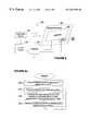
- Display system 100includes a light modulating display 102 , an illumination device 104 , which provides the light source for display 102 , and an adjustable current source 106 electrically connected to illumination device 104 .
- Adjustable current source 106is manually adjusted during manufacturing in order to cause illumination device 104 to provide calibrated light. The adjustment takes place by comparing the illumination output of illumination device 104 to a reference intensity and adjusting current source 106 until the illumination output of illumination device 104 matches the reference intensity. If illumination device 104 contains more than one light source, the process is repeated for each light source.
- Display system 100further includes a controller 108 and a display information input 110 .
- controller 108receives display information via input 110 and determines the current to be supplied to illumination device 104 .
- the setting made during manufacturing to adjustable current source 106causes the current to vary proportionally to the setting, thereby providing partially calibrated light. Because the adjustment made to adjustable current source 106 during manufacturing calibrates the illumination output of illumination device 104 for only a single intensity, this system does not correct the non-linear illumination response to current of illumination device 104 across the device's entire current-controlled operating range.
- Display system 100includes the additional limitation that adjustable current source 106 must be manually set during manufacturing. Having to manually calibrate the current source increases the cost of producing such a device.
- FIG. 2illustrates a display system that overcomes this particular limitation.
- Display system 120includes a voltage source 122 and an adjustable resistor 124 .
- Adjustable resistor 124may be a laser trim resistor that is capable of being adjusted during manufacturing using an automated process to provide the desired intensity for a specific voltage. While this method overcomes one limitation of display system 100 by allowing the calibration to be accomplished by automated means during manufacturing, display system 120 similarly fails to correct the non-linear illumination response to current of illumination device 104 across its entire current-controlled operating range. Further, neither display system 100 nor display system 120 is capable of correcting illumination device variations that occur after manufacturing, such as illumination device aging.
- the present inventiondiscloses arrangements and methods for calibrating illumination devices to reduce both pre- and post-manufacturing variations, including non-linear illumination output as a function of current across the current-controlled operating range and illumination device aging.
- a display systemincluding an arrangement for calibrating an input-driven illumination device.
- the display systemincludes a spatial light modulator divided into an array of individually controllable pixels and an input-driven illumination device which is adapted to receive a variable input and which is configured to direct light of variable intensity onto the modulator, depending on the input.
- the display systemfurther includes an arrangement adapted for connection with the illumination device for providing to the illumination device a specific input for a desired intensity level of the light, the specific input being provided from calibration information particular to the illumination device.
- the arrangementfurther includes a memory device for storing the calibration information.
- a method of operating a display system as described aboveincludes determining calibration information for an input driven illumination device which is adapted to receive a variable input and which is configured to direct light of variable intensity onto a light modulator, depending on the input.
- the methodfurther includes storing the calibration information in a memory device and establishing a specific input for a desired intensity level of the light from the calibration information.
- the methodfurther includes providing the specific input to the illumination device, and directing the light of the desired intensity level onto the light modulator.
- an illumination assemblyincluding calibration information.
- the illumination assemblyincludes an input-driven illumination device which is adapted to receive a variable input and which is configured to produce light of variable intensity depending on the input.
- the illumination assemblyfurther includes an arrangement including a memory device for storing calibration information and generating from the information a specific input for causing the illumination device to produce light of a particular intensity.
- the arrangementis adapted to be connected with the illumination device such that the latter receives the specific input.
- the display systemin another embodiment, includes a light modulator and an input-driven illumination device which has been pre-calibrated to provide light of a given intensity in response to a particular input and which is configured to direct the light onto the modulator.
- the display systemfurther includes an electronic storage arrangement for storing a value which corresponds to the particular input, and an arrangement responsive to the value in the electronic storage means for generating the particular input and using it to drive the illumination device in a way which provides light of the given intensity.
- a method of operating a display system as described aboveincludes determining a particular value for controlling the input to an input-driven illumination device and electronically storing the particular value. The method further includes driving the illumination device in response to the particular value in a way which produces light of a desired intensity level, and directing the light of the desired intensity level onto a light modulator.
- the display systemincludes a light modulator divided into an array of individually controllable pixels and an input-driven illumination device which is adapted to receive a variable input and which is configured to direct light of variable intensity onto the modulator, depending on the input.
- the display systemfurther includes a calibrating arrangement for establishing the input for a desired intensity level of the light.
- the arrangementincludes a light sensing mechanism, which senses the light from the illumination device while the illumination device is driven by an initial input.
- the calibration arrangementis configured to determine a comparison between the sensed light and a value representative of the desired intensity level.
- the calibration arrangementfurther includes a control arrangement responsive to the comparison for varying the input so as to provide light of the desired intensity level.
- the light sensing mechanismmay form part of the light modulator.
- the input-driven illumination device in either of the aforementioned display systems or the aforementioned illumination assemblymay contain one, and only one, light source.
- the illumination devicemay include a plurality of light sources, wherein the calibration arrangement is designed to establish the input for a desired intensity level for each light source, so as to produce combined light of a desired color.
- the particular intensity of light produced by each light sourcemay be different.
- the desired colormay be white.
- the illumination devicemay consist of red, green and blue light-emitting diodes.
- the sensing mechanismmay be a photodetector.
- the sensing mechanismmay be configured to sense only light within the visible spectrum.
- the sensing mechanismmay be configured to have photopic spectral response substantially similar to the human eye.
- a method of operating the immediately aforementioned display systemincludes providing an input-driven illumination device which is adapted to receive a variable input and which is configured to direct light of variable intensity onto a light modulator depending on the input.
- the methodfurther includes sensing the light from the illumination device while the illumination device is driven by an initial input and comparing the sensed light to a value representative of the desired intensity.
- the methodfurther includes establishing the input for a desired intensity level of the light in response to the comparison and directing the light of the desired intensity level onto the light modulator.
- the spectral response of the photodetectormay vary from photodetector to photodetector, and the value representative of the desired intensity level is pre-calibrated to vary proportionally with the photodetector spectral response variation.
- the sensing mechanismmay include a plurality of photodetectors, each configured to sense light of a specific range of wavelengths and wherein each range of wavelengths is different.
- a color displayin another embodiment, includes a light modulator and a plurality of different colored lights, each of which are pre-calibrated to provide light of a given intensity in response to an input of a particular value.
- the lightsare configured to direct the light onto the modulator.
- This embodimentincludes an improvement that includes an electronic storage arrangement for storing the particular value and a control arrangement responsive to the particular value in the electronic storage arrangement for driving the light sources in a way which provides light of the given intensity.
- FIG. 1is a diagrammatic illustration of a first prior art display system.
- FIG. 2is a diagrammatic illustration of an alternative prior art display system.
- FIG. 3is a diagrammatic illustration of a first embodiment of a display system designed in accordance with the present invention.
- FIG. 4is a diagrammatic illustration of a calibration arrangement for calibrating a display system designed in accordance with the present invention.
- FIG. 5is a diagrammatic illustration of a second embodiment of a display system designed in accordance with the present invention.
- FIG. 6is a diagrammatic illustration of a third embodiment of a display system designed in accordance with the present invention.
- FIG. 6 ais a flow diagram illustrating the various steps of a method of operating a display system in accordance with the invention.
- FIG. 7is a diagrammatic illustration of a fourth embodiment of a display system designed in accordance with the present invention.
- FIG. 8is a diagrammatic illustration of a fifth embodiment of a display system designed in accordance with the present invention.
- FIG. 9is a diagrammatic illustration of a sixth embodiment of a display system designed in accordance with the present invention.
- An inventionis herein described for providing methods and arrangements for calibrating the illumination output of illumination devices used, for instance, in display applications.
- numerous specific detailsare set forth in order to provide a thorough understanding of the present invention.
- the present inventionmay be embodied in a wide variety of specific configurations.
- known manufacturing processeswill not be described in detail.
- the various components used to produce illumination devices and display systems, other than the novel circuitrywill not be described in detail. These components are known to those skilled in the art of display systems and their associated illumination devices.
- Display system 200includes an illumination assembly 202 and a light modulating display 204 having an array of pixels 205 .
- One such novel display systemis disclosed in U.S. Pat. No. 5,748,164, entitled ACTIVE MATRIX LIQUID CRYSTAL IMAGE GENERATOR, and issued May 5, 1998, which patent is incorporated herein by reference.
- a display system of this typeis further described in U. S. Pat. No. 5,808,800, entitled OPTICS ARRANGEMENTS INCLUDING LIGHT SOURCE ARRANGEMENTS FOR AN ACTIVE MATRIX LIQUID CRYSTAL IMAGE GENERATOR, and issued Sep.
- Illumination assembly 202provides the light source for light-modulating display 204 .
- Those skilled in the art of micro-displaysunderstand that images are displayed on display system 200 by switching pixels 205 between various optical states in response to image data supplied at the display information input I, thereby forming a pattern of modulated light.
- the systemis operated by displaying image frames at a certain frame rate in order to produce a viewable image.
- each frameis typically divided into subframes or fields for sequentially displaying each of the different primary-color separations of the image. These color fields are displayed at a rate faster than the critical flicker frequency of the human eye. Therefore, the color fields of the different colors are integrated by the viewer's eye.
- the color sensed by the eye of a person viewing the displaydepends on the ratio of intensities of the primary colors in any given portion of the image displayed.
- the relative intensities of the light sources at different brightness levelsare therefore important to producing the correct colors in the final image. It is sufficient, however, to calibrate the light source to produce white light at a desired color and intensity, because the system is thereby calibrated to produce other colors correctly when the system is operated as described above.
- illumination assembly 202further includes a memory device 206 and an illumination device 208 .
- Memory device 206may be any standard electronic memory device.
- memory device 206is a semiconductor memory such as an SRAM (static random access memory) or DRAM (dynamic random access memory).
- memory device 206is a non-volatile semiconductor memory such as a programmable read-only memory (PROM), EEPROM (electrically erasable programmable read-only memory), or “flash” memory device.
- Illumination device 208may be LEDs, laser diodes, incandescent lamps, fluorescent lamps, or any other illumination device capable of being calibrated.
- Calibration methodsmay include adjusting the illumination device drive current, voltage, and/or any other parameter(s) that changes the illumination intensity.
- memory device 206 and illumination device 208the present invention is not limited to these specific examples; other devices may be used that nevertheless remain within the scope of the present invention.
- Memory device 206may store one or more calibrating values, each representing the current required to provide light of a specific intensity from illumination device 208 .
- the calibrating valuesare determined and placed in memory device 206 utilizing the calibration arrangement such as calibration arrangement 210 of FIG. 4 .
- Calibration arrangement 210includes a current source 212 , a light sensing device 214 to measure the intensity of light from illumination device 208 , a calibration controller 216 connected electrically to light sensing device 214 , and a reference value storage device 218 connected electrically to calibration controller 216 .
- Light sensing device 214may be a photodetector or any other device capable of converting an optical signal into an electrical signal representative of the illumination intensity of the optical signal.
- current source 212supplies a specific current to illumination device 208 .
- Light sensing device 214measures the intensity of the light produced by illumination device 208
- calibration controller 216compares the measured intensity unique to illumination device 208 to a reference value representing the desired intensity, the reference value being stored in reference value storage device 218 .
- the reference valuemay be obtained by exposing the same light sensing device 214 to a reference or standard light source 219 and causing the value of the measured light level to be stored in the reference value storage device 218 . Based on the comparison, calibration controller 216 causes current source 212 to vary the current supplied to illumination device 208 until the intensity of light provided by illumination device 208 matches the reference intensity.
- calibration controller 216causes a calibrating value unique to illumination device 208 to be stored in memory device 206 .
- the calibrating valuemay be the specific current required to produce light of the desired intensity, or any other calibrating value capable of allowing a controller 220 of FIG. 3 to determine the correct current to provide to illumination device 208 in order to produce light of the desired intensity.
- the processmay be repeated for a plurality of desired intensity levels.
- memory device 206may store a plurality of calibrating values representing the current required to produce light of various specific intensities.
- display system 200further includes controller 220 electrically connected to memory device 206 and a current source 222 .
- current source 222is also electrically connected to illumination device 208 .
- the current sourceprovides electrical drive appropriate to the illumination device and can be of any of the types well known in the art associated with the various types of illumination devices. In particular, if the illumination device is made from LEDs, in may be preferred to provide electrical drive whose drive current does not depend on the LED forward voltage drop. Electronic circuits of this capability are well known in the art.
- current source 222may respond to a digital input from controller 220 , in which case current source 222 may incorporate a digital-to-analog converter (DAC) giving it the capability of providing an output current that varies in response to a digital input from the controller.
- DACdigital-to-analog converter
- light modulating display 204can be implemented on a silicon integrated circuit.
- controller 220 and current source 222may also be implemented on the same integrated circuit.
- controller 220receives display information via input I. Controller 220 uses the display information in combination with the calibrating value stored in memory device 206 to cause current source 222 to provide the particular amount of current to illumination device 208 in order to produce light of a desired intensity.
- the desired intensity of light to be produced at any particular timemay be the same as or different from the intensities for which calibrating values are stored in memory device 206 . For example, if the desired intensity is the same intensity for which a calibrating value is stored in memory device 206 , then controller 220 causes current source 222 to provide current corresponding to that value.
- controller 220interpolates between values to determine the correct current to produce light of the desired intensity. If only one calibrating value is stored in memory device 206 , then controller 220 interpolates between that calibrating value and zero current, which represents zero intensity, to determine the current necessary to produce light of the desired intensity. Controller 220 then causes current source 222 to provide that current to illumination device 208 . This method of interpolating between multiple calibrating values stored in memory device 206 provides the advantage that illumination assembly 202 may be calibrated to correct the non-linear response illumination device 208 has to current.
- illumination device 224includes a plurality of light sources, specifically red, green and blue light-emitting diodes (LEDs) indicated by reference numbers 226 a-c .
- Memory device 206stores one or more calibrating values for each light source, each value representing the current required to provide light of a particular intensity for the associated light source. Ideally, memory device 206 stores the calibrating values for each light source representing the current required for each light source to produce light that, when combined, produces light of a chosen color, color temperature, and/or white point. Further, if memory device 206 is configured to store more than one value for each light source, the stored values represent the current required to produce white light at various specific brightness levels.
- illumination assembly 202when operated as described above, is calibrated to provide a stable white-point for various brightness levels.
- the calibrating values stored in memory device 206 for each light source of illumination device 224are determined and placed in memory device 206 using a calibration arrangement such as calibration arrangement 210 of FIG. 4 as described above.
- the calibration processis carried out in a way similar to that described above with reference to FIG. 4 .
- Current source 212supplies current to each light source 226 a-c in sequence. As each light source is illuminated, light sensing device 214 measures the intensity of light produced, and calibration controller 216 compares the measured intensity to a reference value from reference value storage device 218 . Calibration controller 216 then causes current source 212 to vary the current until the light source is producing light of the desired intensity.
- Calibration controllerthen causes calibration information unique to the light source to be stored in memory device 206 .
- the processis repeated for each light source 226 a-c and for all desired brightness levels of each light source.
- memory device 206ultimately contains values unique to each light source 226 a-c.
- the reference values stored in device 218may preferably have been obtained in sequence by exposing the same light sensing device 214 to a reference light source that produces a sequence of red, green, and blue illuminations.
- a reference light sourcethat produces a sequence of red, green, and blue illuminations.
- the spectra of the red, green, and blue illuminations provided by the reference light sourcematch the spectra of the red, green, and blue LEDs of light source 224 .
- the present embodimenthas been described having RGB LEDs, it should be understood that the present invention is not limited to RGB LEDs or even LEDs.
- the present inventionmay be used to calibrate any light source, combination of light sources and/or combination of colors of light sources.
- illumination device 224has been described as being configured to produce white light with a stable white-point, this is not a requirement. Instead, light sources with a wide variety of colors may be mixed in a wide variety of manners to produce any desired color when combined.
- the controller and/or current sourcecan be fabricated with display 204 as a single integrated circuit.
- illumination assembly 202Often in manufacturing operations, components such as display 204 , illumination assembly 202 , current source 222 and controller 220 are not assembled into a combined product until late in the manufacturing process.
- the calibration process of FIG. 4may take place early in the manufacturing process. This is because the particular illumination device contained on the sub-assembly remains coupled throughout the manufacturing process with memory device 206 and the calibrating value stored therein that is unique to that specific illumination device.
- illumination assembly 202may be integrated with any combination of controller 220 , current source 222 and display 204 , without requiring further calibration, again because the unique calibrating value for the illumination device remains coupled with the illumination device.
- memory device 206is capable of maintaining the calibrating values without requiring an external power source.
- PROMprogrammable read-only memory
- the present inventionis not limited to PROM; any memory device capable of maintaining its stored value without external power may be used.
- illumination assembly 202may include an appropriate power supply 228 such as a battery or capacitor to power the memory device, and allow it to retain its calibration values during the interval between the calibration operation and the use of the display.
- FIG. 6illustrates a display system 230 designed in accordance with the present invention.
- Display system 230includes an illumination device 232 electrically connected to a controller 233 via a current source 234 .
- Display system 230further includes a display backplane 236 , which is illuminated by illumination device 232 .
- Display system 230further includes a light modulating display 240 and a light sensing device 242 .
- Light modulating device 240operates to form images, as previously described.
- Light sensing device 242may be a photodetector or any other device capable of converting an optical signal into an electrical signal representative of the illumination intensity of the optical signal.
- display backplane 236can be implemented as a silicon integrated circuit. In this case light sensing device 242 can easily be implemented on the same integrated circuit, for example as a photodiode or phototransistor, using techniques well known in the integrated circuit art. Controller 233 and current source 234 may also be implemented on the same integrated circuit.
- illumination device 232illuminates display backplane 236 in response to current supplied by current source 234 .
- Current source 234provides current in response to control information provided by controller 233 .
- Controller 233determines the control information to supply to current source 234 based on information supplied by light sensing device 242 in combination with display information from a display information input I.
- the display information supplied via display information input Iincludes information directing a desired intensity level of light to be supplied by illumination device 232 .
- Controller 233compares this desired intensity level with the output from light sensing device 242 , which represents the intensity of light being sensed. Controller 233 then varies the control information supplied to current source 234 so as to adjust the intensity of light from illumination device 232 until it matches the desired intensity.
- the calibration arrangement of display system 230acts as a servomechanism with continuous feedback for adjusting the light output of illumination device 232 to achieve and maintain the desired intensity of light.
- display system 230includes illumination device 232 and display 240 .
- the methodincludes the step of causing the illumination device to illuminate the display by driving it with an initial input as indicated by block 246 .
- this methodfurther includes the step of sensing the light from the illumination device.
- Block 248includes the step of comparing the signal representative of the intensity of the sensed light to a signal representative of the desired intensity of light.
- block 249includes the step of determining a new input for the illumination device, based on the comparison from the previous step, for causing the illumination device to produce light of the desired intensity.
- Illumination device 232 of FIG. 6could contain multiple light sources of different colors, in the same manner as was described with reference to FIG. 5, to create a sequentialcolor display system.
- the calibration servomechanism, with single light sensing device 242can function nevertheless according to the above method.
- Controller 233switches each different-colored light source within illumination device 232 on one at a time.
- Light sensing device 242measures in turn the intensity of each light source, and controller 233 acts on current source 234 to bring the measured intensity to its desired value.
- FIG. 7illustrates a display system 250 designed in accordance with the present invention and containing many of the same elements of display system 230 of FIG. 6 .
- the display backplane 256 of display system 250further includes a comparator 264 , a reference value storage device 266 and a calibrating value storage device 267 .
- reference value storage device 266may be non-volatile programmable read-only memory, or may be conventional SRAM or DRAM circuitry, or circuitry designed to represent a specific value or values.
- display system 250includes input I 2 , for selecting specific memory locations within reference value storage device 266 .
- Comparator 264is electrically connected to both light sensing device 242 and reference value storage device 266 .
- Comparator 264is configured for comparing values representing sensed light intensity received from light sensing device 242 , to reference intensities provided by reference value storage device 266 and selected from reference value storage device 266 using information from input 12 .
- Comparator 264is also electrically connected to calibrating value storage device 267 .
- Calibrating value storage device 267may be any programmable memory capable of being reprogrammed with new information following a calibration process.
- illumination device 232illuminates display backplane 256 in response to current supplied by current source 234 .
- Current source 234provides current in response to control information provided by controller 233 .
- Controller 233determines the control information to supply to current source 234 based on information supplied from calibrating value storage device 267 in combination with display information from a display information input I.
- the information supplied from calibrating value storage device 267is calibration information determined during a calibration process.
- illumination device 232is driven by a reference current from current source 234 .
- Light sensing device 242senses the light from illumination device 232 and provides light intensity information to comparator 264 .
- Comparator 264compares the sensed light with a reference value from reference value storage device 266 . This reference value may be derived from an earlier exposure of light sensing device 242 to a reference light source, as described previously. Comparator 264 then causes a calibrating value that is unique to illumination device 232 to be stored in calibrating value storage device 267 . Controller 233 later uses the comparison to appropriately adjust the control information supplied to current source 234 , thereby varying the current supplied to illumination device 232 in proportion to the comparison.
- calibrating value storage device 267must be capable of storing values representing calibration information for all light sources and all brightness levels. For example, if three light sources are included in illumination device 232 and values are stored for two brightness levels, then calibrating value storage device 267 must contain six memory locations.
- calibrating value storage device 267is not capable of maintaining its stored values without external power. As a result, the calibration process described above must be repeated following each external power interruption.
- this configurationprovides the advantage that the calibration process corrects post-manufacturing variations, such as LED aging, that result in light source intensity differences.
- calibrating value storage device 267could be non-volatile memory, such as flash, or a readily providable power source could be easily incorporated into display backplane 256 of display system 250 as demonstrated by power source 270 of FIG. 7 . This would allow calibration to take place during manufacturing and negate the need to recalibrate the system following each power interruption.
- the present embodimentfunctions best if the part-to-part spectral response variation of light sensing device 242 is small.
- the following embodimentprovides a display system that functions correctly even with large spectral variation.
- FIG. 8illustrates a display system 300 that functions in a similar manner to display system 250 of FIG. 7, except that display system 300 includes a reference value storage device 302 and a display backplane 304 .
- Reference value storage device 302 of display system 300need not be located on display backplane 304 as in display system 250 .
- Reference value storage device 302is made of a non-volatile memory type, or is provided with a power supply.
- reference value storage device 302contains reference intensity information as described in the previous embodiment, the reference value(s) for the present embodiment is/are adjusted during a sensing device calibration manufacturing process to account for spectral response variation of light sensing device 242 .
- the sensing device manufacturing calibration processtakes place as follows.
- display backplane 304is illuminated by light of a reference intensity and color.
- Light sensing device 242measures the intensity of the light, and the intensity reference value that is unique to light sensing device 242 is stored in reference value storage device 302 . The process is repeated for each light source within illumination device 232 (for example, different colored LEDs) and all desired brightness levels for each of those light sources.
- the reference valueis provided to comparator 264 during a calibration process as described for display system 256 of FIG. 7 .
- this embodimentcorrects the spectral response variation of light sensing device 242 .
- illumination device 232Some light sources that may be included in illumination device 232 have the potential for emitting light with a wavelength outside the visible spectrum. Because light sensing device 242 is not necessarily limited to sensing light of wavelengths within the visible spectrum, light emitted by illumination device 232 outside the visible spectrum will be sensed, and the calibration process may provide inaccurate calibration information. In order to overcome the aforementioned potential problem, a filter 306 may be positioned over light sensing device 242 . Filter 306 may be designed to pass only light having a wavelength within the visible spectrum, thereby preventing any light from outside the visible range being measured by light sensing device 242 .
- filter 306may be designed to solve yet another potential problem that may arise in display system applications.
- Part-to-part spectral output variation for a typical light source used in display system applicationsmay produce unacceptable color balance and white-point stability, even when calibrated in accordance with the present invention. This occurs because the typical light sensing device measures light intensity irrespective of the wavelength of light being measured. Therefore, a light source may produce light of an undesired wavelength, yet this fact would go undetected by the previously described display systems.
- filter 306may be a photopic response filter having the same wavelength variation sensitivity as a human eye. As a result, the light sensing device will have the same response to light source spectral variations as the human eye, and desired white-point calibration will be obtained.
- Display backplane 322 of display system 320includes a plurality of light sensing devices 324 a-c , each configured to measure only light of a specific range of wavelengths, and each configured to measure a different range of wavelengths of light.
- display system 320could include three light sensing devices for measuring the three primary colors, red, green and blue.
- Light sensing devices 324 a-cmay have filters 326 a-c positioned so as to filter the light being sensed by devices 324 a-c .
- light sensing devices 324 a-cmay be photodetectors specifically designed with a particular spectral response variation so as to be more sensitive to light within specific wavelength ranges.
- spectral sensitivitycan be tailored by the design of the photodetector, for example whether or not the photodetector is implemented directly in the silicon substrate or is alternately implemented in a CMOS well.
- light sensing devices 324 a-cmeasure the intensity of light from individual light sources contained in illumination device 232 .
- Comparator 264compares the measured intensities to reference values for the specific wavelengths of sensed light and causes the comparison information to be stored in calibrating value storage device 267 . Controller 233 later uses the comparison to appropriately adjust the control information supplied to current source 234 , thereby varying the current supplied to illumination device 232 in proportion to the comparison.
- the present inventionmay take on a wide variety of specific configurations and still remain within the scope of the present invention.
- the invention embodied in display system 320 of FIG. 9may be embodied in a display system similar to display system 230 of FIG. 6 (i.e., without elements comparator 264 , calibration value storage device 267 , and reference value storage device 302 ). Therefore, the present examples are to be considered as illustrative and not restrictive, and the invention is not to be limited to the details given herein, but may be modified within the scope of the appended claims.
Landscapes
- Engineering & Computer Science (AREA)
- Physics & Mathematics (AREA)
- Computer Hardware Design (AREA)
- General Physics & Mathematics (AREA)
- Theoretical Computer Science (AREA)
- Control Of Indicators Other Than Cathode Ray Tubes (AREA)
- Circuit Arrangement For Electric Light Sources In General (AREA)
Abstract
Description
Claims (28)
Priority Applications (1)
| Application Number | Priority Date | Filing Date | Title |
|---|---|---|---|
| US09/313,227US6633301B1 (en) | 1999-05-17 | 1999-05-17 | RGB illuminator with calibration via single detector servo |
Applications Claiming Priority (1)
| Application Number | Priority Date | Filing Date | Title |
|---|---|---|---|
| US09/313,227US6633301B1 (en) | 1999-05-17 | 1999-05-17 | RGB illuminator with calibration via single detector servo |
Publications (1)
| Publication Number | Publication Date |
|---|---|
| US6633301B1true US6633301B1 (en) | 2003-10-14 |
Family
ID=28791819
Family Applications (1)
| Application Number | Title | Priority Date | Filing Date |
|---|---|---|---|
| US09/313,227Expired - Fee RelatedUS6633301B1 (en) | 1999-05-17 | 1999-05-17 | RGB illuminator with calibration via single detector servo |
Country Status (1)
| Country | Link |
|---|---|
| US (1) | US6633301B1 (en) |
Cited By (84)
| Publication number | Priority date | Publication date | Assignee | Title |
|---|---|---|---|---|
| US20030214638A1 (en)* | 2002-05-16 | 2003-11-20 | Nec Viewtechnology, Ltd. | Projector and lamp information management method used for the same |
| US20040165068A1 (en)* | 2003-02-25 | 2004-08-26 | Jane Rone Fue | Projector color calibration device and method |
| US20040263502A1 (en)* | 2003-04-24 | 2004-12-30 | Dallas James M. | Microdisplay and interface on single chip |
| US20050041003A1 (en)* | 2002-02-01 | 2005-02-24 | Seiko Epson Corporation | Electro-optical device, driving method thereof, and electronic apparatus |
| US20050179628A1 (en)* | 2001-09-07 | 2005-08-18 | Semiconductor Energy Laboratory Co., Ltd. | Light emitting device and method of driving the same |
| US20050225683A1 (en)* | 2004-04-12 | 2005-10-13 | Seiko Epson Corporation | Electro-optical device and electronic apparatus |
| US20060017687A1 (en)* | 2004-07-20 | 2006-01-26 | Alps Electric Co., Ltd. | Liquid crystal display device |
| US20060038509A1 (en)* | 2004-08-19 | 2006-02-23 | Yi-Fang Lin | LED optical energy detection and feedback system |
| US20060049332A1 (en)* | 2004-09-08 | 2006-03-09 | Vornsand Steven J | Method of adjusting multiple light sources to compensate for variation in light output that occurs with time |
| US20060092209A1 (en)* | 2004-10-28 | 2006-05-04 | Carles Flotats | Illumination utilizing a plurality of light sources |
| US20060098123A1 (en)* | 2004-11-08 | 2006-05-11 | Antoine Simkine | Image processing device |
| US20060227147A1 (en)* | 2005-04-07 | 2006-10-12 | Toon Diels | Method and apparatus for an image presentation device with illumination control for black image processing |
| US20070001941A1 (en)* | 2005-07-04 | 2007-01-04 | Semiconductor Energy Laboratory Co., Ltd. | Semiconductor device and driving method thereof |
| US20070115662A1 (en)* | 2005-11-18 | 2007-05-24 | Cree, Inc. | Adaptive adjustment of light output of solid state lighting panels |
| US20070115228A1 (en)* | 2005-11-18 | 2007-05-24 | Roberts John K | Systems and methods for calibrating solid state lighting panels |
| US7227519B1 (en)* | 1999-10-04 | 2007-06-05 | Matsushita Electric Industrial Co., Ltd. | Method of driving display panel, luminance correction device for display panel, and driving device for display panel |
| US20070126656A1 (en)* | 2005-12-07 | 2007-06-07 | Industrial Technology Research Institute | Illumination brightness and color control system and method therefor |
| US20070146182A1 (en)* | 2005-12-23 | 2007-06-28 | Hsin-Hung Chen | Self-calibrating current source arrays |
| US20070216704A1 (en)* | 2005-11-18 | 2007-09-20 | Cree, Inc. | Systems and methods for calibrating solid state lighting panels using combined light output measurements |
| US20070278974A1 (en)* | 2006-05-31 | 2007-12-06 | Led Lighting Fixtures, Inc. | Lighting device with color control, and method of lighting |
| US20070285378A1 (en)* | 2006-06-09 | 2007-12-13 | Philips Lumileds Lighting Company, Llc | LED Backlight for LCD with Color Uniformity Recalibration Over Lifetime |
| US20080012820A1 (en)* | 2006-07-11 | 2008-01-17 | Chun-Chieh Yang | System and method for achieving desired operation illumination condition for light emitters |
| US20080024674A1 (en)* | 2006-02-06 | 2008-01-31 | Toshiba America Consumer Products, Llc. | Brightness control system and method |
| US20080036943A1 (en)* | 2004-05-11 | 2008-02-14 | Tatsuhiko Matsumoto | Backlight Device and Color Liquid Crystal Display |
| US20080074382A1 (en)* | 2006-07-20 | 2008-03-27 | Sang-Gil Lee | Display device, control method thereof, and backlight unit used therefor |
| US20080100551A1 (en)* | 2004-10-20 | 2008-05-01 | Sony Corporation | Color Liquid Crystal Display Apparatus |
| US20080129680A1 (en)* | 2006-12-01 | 2008-06-05 | Sony Corporation | Apparatus and method for controlling backlight and liquid crystal display |
| US20080174544A1 (en)* | 2007-01-24 | 2008-07-24 | Sony Corporation | Backlight apparatus, backlight controlling method and liquid crystal display apparatus |
| US7405852B2 (en) | 2005-02-23 | 2008-07-29 | Pixtronix, Inc. | Display apparatus and methods for manufacture thereof |
| US20080186433A1 (en)* | 2004-07-15 | 2008-08-07 | Shuichi Haga | Color Filter and Color Liquid Crystal Display Apparatus |
| US20080283737A1 (en)* | 2007-05-14 | 2008-11-20 | Au Optronics Corporation | Backlight module and calibration method thereof |
| US20080300661A1 (en)* | 2003-12-11 | 2008-12-04 | Star Energetics Holding Company | Perceptible Apparatus and Methods for Reactive Effect |
| US20090033613A1 (en)* | 2007-07-31 | 2009-02-05 | Mark Butterworth | Liquid crystal display |
| US20090058307A1 (en)* | 2007-08-29 | 2009-03-05 | Osram Gesellschaft Mit Beschrankter Haftung | Illumination device and method for adapting an emission characteristic of an illumination device |
| EP1564711B1 (en)* | 2004-02-13 | 2009-04-15 | Hewlett-Packard Development Company, L.P. | Light delivery device |
| US7551344B2 (en) | 2005-02-23 | 2009-06-23 | Pixtronix, Inc. | Methods for manufacturing displays |
| US20090180039A1 (en)* | 2003-11-01 | 2009-07-16 | Taro Endo | Video display system |
| US20090231440A1 (en)* | 2008-03-14 | 2009-09-17 | Innocom Technology (Shenzhen) Co., Ltd. | Brightness automatically adjusting system and method for adjusting brightness thereof |
| WO2009123605A1 (en)* | 2008-03-31 | 2009-10-08 | Hewlett-Packard Development Company, L.P. | Rgb led control using vector calibration |
| US7636189B2 (en) | 2005-02-23 | 2009-12-22 | Pixtronix, Inc. | Display methods and apparatus |
| US20100045690A1 (en)* | 2007-01-04 | 2010-02-25 | Handschy Mark A | Digital display |
| US7724316B2 (en) | 2006-09-22 | 2010-05-25 | Sony Corporation | Backlight device and display apparatus |
| EP1936602A3 (en)* | 2006-12-22 | 2010-06-02 | Samsung Electronics Co., Ltd. | Display apparatus and color temperature control method thereof |
| CN101286301B (en)* | 2007-04-11 | 2010-06-16 | 财团法人工业技术研究院 | Apparatus for driving light emitting semiconductor device and method thereof |
| US7746529B2 (en) | 2005-02-23 | 2010-06-29 | Pixtronix, Inc. | MEMS display apparatus |
| US7755582B2 (en) | 2005-02-23 | 2010-07-13 | Pixtronix, Incorporated | Display methods and apparatus |
| US7852546B2 (en) | 2007-10-19 | 2010-12-14 | Pixtronix, Inc. | Spacers for maintaining display apparatus alignment |
| US7876489B2 (en) | 2006-06-05 | 2011-01-25 | Pixtronix, Inc. | Display apparatus with optical cavities |
| US7927654B2 (en) | 2005-02-23 | 2011-04-19 | Pixtronix, Inc. | Methods and apparatus for spatial light modulation |
| WO2011137442A1 (en)* | 2010-04-30 | 2011-11-03 | Marvell World Trade Ltd | System and method of tuning current for leds |
| US20110273700A1 (en)* | 2008-07-21 | 2011-11-10 | John Henry Lambert | Sound-creation interface |
| US8159428B2 (en) | 2005-02-23 | 2012-04-17 | Pixtronix, Inc. | Display methods and apparatus |
| CN101437340B (en)* | 2008-12-22 | 2012-05-09 | 浙江生辉照明有限公司 | Automatic calibration instrument and calibration method for RGB chatoyancy LED lamp |
| CN102542996A (en)* | 2010-12-31 | 2012-07-04 | 深圳市长运通光电技术有限公司 | Light-emitting diode (LED) wavelength correcting circuit |
| US8248560B2 (en) | 2008-04-18 | 2012-08-21 | Pixtronix, Inc. | Light guides and backlight systems incorporating prismatic structures and light redirectors |
| US8262274B2 (en) | 2006-10-20 | 2012-09-11 | Pitronix, Inc. | Light guides and backlight systems incorporating light redirectors at varying densities |
| US8310442B2 (en) | 2005-02-23 | 2012-11-13 | Pixtronix, Inc. | Circuits for controlling display apparatus |
| CN103162179A (en)* | 2011-12-12 | 2013-06-19 | 三星显示有限公司 | A backlight |
| US8482496B2 (en) | 2006-01-06 | 2013-07-09 | Pixtronix, Inc. | Circuits for controlling MEMS display apparatus on a transparent substrate |
| CN101998724B (en)* | 2009-08-21 | 2013-08-21 | 深圳市长运通光电技术有限公司 | Method and system for correcting light emission of light emitting diode module group |
| US8519945B2 (en) | 2006-01-06 | 2013-08-27 | Pixtronix, Inc. | Circuits for controlling display apparatus |
| US8520285B2 (en) | 2008-08-04 | 2013-08-27 | Pixtronix, Inc. | Methods for manufacturing cold seal fluid-filled display apparatus |
| US8526096B2 (en) | 2006-02-23 | 2013-09-03 | Pixtronix, Inc. | Mechanical light modulators with stressed beams |
| US20130257894A1 (en)* | 2005-03-29 | 2013-10-03 | Texas Instruments Incorporated | Spatial light modulation display system |
| US8599463B2 (en) | 2008-10-27 | 2013-12-03 | Pixtronix, Inc. | MEMS anchors |
| US8749538B2 (en) | 2011-10-21 | 2014-06-10 | Qualcomm Mems Technologies, Inc. | Device and method of controlling brightness of a display based on ambient lighting conditions |
| US8866410B2 (en) | 2007-11-28 | 2014-10-21 | Cree, Inc. | Solid state lighting devices and methods of manufacturing the same |
| US9082353B2 (en) | 2010-01-05 | 2015-07-14 | Pixtronix, Inc. | Circuits for controlling display apparatus |
| US9087486B2 (en) | 2005-02-23 | 2015-07-21 | Pixtronix, Inc. | Circuits for controlling display apparatus |
| US9134552B2 (en) | 2013-03-13 | 2015-09-15 | Pixtronix, Inc. | Display apparatus with narrow gap electrostatic actuators |
| US9135868B2 (en) | 2005-02-23 | 2015-09-15 | Pixtronix, Inc. | Direct-view MEMS display devices and methods for generating images thereon |
| US9158106B2 (en) | 2005-02-23 | 2015-10-13 | Pixtronix, Inc. | Display methods and apparatus |
| US9176318B2 (en) | 2007-05-18 | 2015-11-03 | Pixtronix, Inc. | Methods for manufacturing fluid-filled MEMS displays |
| US9183812B2 (en) | 2013-01-29 | 2015-11-10 | Pixtronix, Inc. | Ambient light aware display apparatus |
| US9229222B2 (en) | 2005-02-23 | 2016-01-05 | Pixtronix, Inc. | Alignment methods in fluid-filled MEMS displays |
| US9261694B2 (en) | 2005-02-23 | 2016-02-16 | Pixtronix, Inc. | Display apparatus and methods for manufacture thereof |
| US9398666B2 (en) | 2010-03-11 | 2016-07-19 | Pixtronix, Inc. | Reflective and transflective operation modes for a display device |
| US9500853B2 (en) | 2005-02-23 | 2016-11-22 | Snaptrack, Inc. | MEMS-based display apparatus |
| US10251233B2 (en) | 2012-05-07 | 2019-04-02 | Micron Technology, Inc. | Solid state lighting systems and associated methods of operation and manufacture |
| US11043172B2 (en) | 2018-02-27 | 2021-06-22 | Nvidia Corporation | Low-latency high-dynamic range liquid-crystal display device |
| US11238815B2 (en)* | 2018-02-27 | 2022-02-01 | Nvidia Corporation | Techniques for updating light-emitting diodes in synchrony with liquid-crystal display pixel refresh |
| WO2022230884A1 (en)* | 2021-04-27 | 2022-11-03 | 日本精機株式会社 | Display device |
| US11636814B2 (en) | 2018-02-27 | 2023-04-25 | Nvidia Corporation | Techniques for improving the color accuracy of light-emitting diodes in backlit liquid-crystal displays |
| US20230245294A1 (en)* | 2020-05-06 | 2023-08-03 | Admesy B.V. | Method and setup for performing a series of optical measurements with a 2d imaging system |
Citations (11)
| Publication number | Priority date | Publication date | Assignee | Title |
|---|---|---|---|---|
| US5287096A (en)* | 1989-02-27 | 1994-02-15 | Texas Instruments Incorporated | Variable luminosity display system |
| US5369432A (en)* | 1992-03-31 | 1994-11-29 | Minnesota Mining And Manufacturing Company | Color calibration for LCD panel |
| US5386253A (en)* | 1990-04-09 | 1995-01-31 | Rank Brimar Limited | Projection video display systems |
| US5483259A (en)* | 1994-04-12 | 1996-01-09 | Digital Light & Color Inc. | Color calibration of display devices |
| US5589852A (en)* | 1989-02-27 | 1996-12-31 | Texas Instruments Incorporated | Apparatus and method for image projection with pixel intensity control |
| US5650844A (en)* | 1994-07-14 | 1997-07-22 | Advantest Corporation | LCD panel image quality inspection system and LCD image presampling method |
| US5748164A (en)* | 1994-12-22 | 1998-05-05 | Displaytech, Inc. | Active matrix liquid crystal image generator |
| US6108053A (en)* | 1997-05-30 | 2000-08-22 | Texas Instruments Incorporated | Method of calibrating a color wheel system having a clear segment |
| US6108122A (en)* | 1998-04-29 | 2000-08-22 | Sharp Kabushiki Kaisha | Light modulating devices |
| US6188427B1 (en)* | 1997-04-23 | 2001-02-13 | Texas Instruments Incorporated | Illumination system having an intensity calibration system |
| US6285349B1 (en)* | 1999-02-26 | 2001-09-04 | Intel Corporation | Correcting non-uniformity in displays |
- 1999
- 1999-05-17USUS09/313,227patent/US6633301B1/ennot_activeExpired - Fee Related
Patent Citations (11)
| Publication number | Priority date | Publication date | Assignee | Title |
|---|---|---|---|---|
| US5287096A (en)* | 1989-02-27 | 1994-02-15 | Texas Instruments Incorporated | Variable luminosity display system |
| US5589852A (en)* | 1989-02-27 | 1996-12-31 | Texas Instruments Incorporated | Apparatus and method for image projection with pixel intensity control |
| US5386253A (en)* | 1990-04-09 | 1995-01-31 | Rank Brimar Limited | Projection video display systems |
| US5369432A (en)* | 1992-03-31 | 1994-11-29 | Minnesota Mining And Manufacturing Company | Color calibration for LCD panel |
| US5483259A (en)* | 1994-04-12 | 1996-01-09 | Digital Light & Color Inc. | Color calibration of display devices |
| US5650844A (en)* | 1994-07-14 | 1997-07-22 | Advantest Corporation | LCD panel image quality inspection system and LCD image presampling method |
| US5748164A (en)* | 1994-12-22 | 1998-05-05 | Displaytech, Inc. | Active matrix liquid crystal image generator |
| US6188427B1 (en)* | 1997-04-23 | 2001-02-13 | Texas Instruments Incorporated | Illumination system having an intensity calibration system |
| US6108053A (en)* | 1997-05-30 | 2000-08-22 | Texas Instruments Incorporated | Method of calibrating a color wheel system having a clear segment |
| US6108122A (en)* | 1998-04-29 | 2000-08-22 | Sharp Kabushiki Kaisha | Light modulating devices |
| US6285349B1 (en)* | 1999-02-26 | 2001-09-04 | Intel Corporation | Correcting non-uniformity in displays |
Cited By (154)
| Publication number | Priority date | Publication date | Assignee | Title |
|---|---|---|---|---|
| US7227519B1 (en)* | 1999-10-04 | 2007-06-05 | Matsushita Electric Industrial Co., Ltd. | Method of driving display panel, luminance correction device for display panel, and driving device for display panel |
| US8947328B2 (en)* | 2001-09-07 | 2015-02-03 | Semiconductor Energy Laboratory Co., Ltd. | Light emitting device and method of driving the same |
| US20050179628A1 (en)* | 2001-09-07 | 2005-08-18 | Semiconductor Energy Laboratory Co., Ltd. | Light emitting device and method of driving the same |
| US7253813B2 (en)* | 2002-02-01 | 2007-08-07 | Seiko Epson Corporation | Electro-optical device, driving method thereof, and electronic apparatus |
| US20050041003A1 (en)* | 2002-02-01 | 2005-02-24 | Seiko Epson Corporation | Electro-optical device, driving method thereof, and electronic apparatus |
| US6802615B2 (en)* | 2002-05-16 | 2004-10-12 | Nec Viewtechnology, Ltd. | Projector and lamp information management method used for the same |
| US20030214638A1 (en)* | 2002-05-16 | 2003-11-20 | Nec Viewtechnology, Ltd. | Projector and lamp information management method used for the same |
| US20040165068A1 (en)* | 2003-02-25 | 2004-08-26 | Jane Rone Fue | Projector color calibration device and method |
| US7283105B2 (en) | 2003-04-24 | 2007-10-16 | Displaytech, Inc. | Microdisplay and interface on single chip |
| US20100245212A1 (en)* | 2003-04-24 | 2010-09-30 | Dallas James M | Microdisplay and interface on a single chip |
| US20080100633A1 (en)* | 2003-04-24 | 2008-05-01 | Dallas James M | Microdisplay and interface on a single chip |
| US20040263502A1 (en)* | 2003-04-24 | 2004-12-30 | Dallas James M. | Microdisplay and interface on single chip |
| US8816999B2 (en) | 2003-04-24 | 2014-08-26 | Citizen Finetech Miyota Co., Ltd. | Adjustment of liquid crystal display voltage |
| US20110227887A1 (en)* | 2003-04-24 | 2011-09-22 | Micron Technology, Inc. | Adjustment of liquid crystal display voltage |
| US7932875B2 (en) | 2003-04-24 | 2011-04-26 | Micron Technology, Inc. | Microdisplay and interface on a single chip |
| US7755570B2 (en) | 2003-04-24 | 2010-07-13 | Micron Technology, Inc. | Microdisplay and interface on a single chip |
| US20090180039A1 (en)* | 2003-11-01 | 2009-07-16 | Taro Endo | Video display system |
| US8350790B2 (en)* | 2003-11-01 | 2013-01-08 | Silicon Quest Kabushiki-Kaisha | Video display system |
| US20080300661A1 (en)* | 2003-12-11 | 2008-12-04 | Star Energetics Holding Company | Perceptible Apparatus and Methods for Reactive Effect |
| EP1564711B1 (en)* | 2004-02-13 | 2009-04-15 | Hewlett-Packard Development Company, L.P. | Light delivery device |
| US20050225683A1 (en)* | 2004-04-12 | 2005-10-13 | Seiko Epson Corporation | Electro-optical device and electronic apparatus |
| US7554514B2 (en)* | 2004-04-12 | 2009-06-30 | Seiko Epson Corporation | Electro-optical device and electronic apparatus |
| US7789527B2 (en) | 2004-05-11 | 2010-09-07 | Sony Corporation | Backlight device and color liquid crystal display |
| US20080036943A1 (en)* | 2004-05-11 | 2008-02-14 | Tatsuhiko Matsumoto | Backlight Device and Color Liquid Crystal Display |
| US7808585B2 (en) | 2004-07-15 | 2010-10-05 | Sony Corporation | Color filter and color LCD apparatus having red filter with a peak wavelength between 685 nm and 690 nm and a red light source having a peak wavelength of between 640 nm and 645 nm |
| US20080186433A1 (en)* | 2004-07-15 | 2008-08-07 | Shuichi Haga | Color Filter and Color Liquid Crystal Display Apparatus |
| JP2006030783A (en)* | 2004-07-20 | 2006-02-02 | Alps Electric Co Ltd | Liquid crystal display device |
| EP1619655A3 (en)* | 2004-07-20 | 2006-05-17 | Alps Electric Co., Ltd. | Liquid crystal display device with coloured back light sources and white balance correction |
| US20060017687A1 (en)* | 2004-07-20 | 2006-01-26 | Alps Electric Co., Ltd. | Liquid crystal display device |
| CN100399128C (en)* | 2004-07-20 | 2008-07-02 | 阿尔卑斯电气株式会社 | Liquid crystal display device |
| US7045974B2 (en)* | 2004-08-19 | 2006-05-16 | Radiant Opto-Electronics Corporation | LED optical energy detection and feedback system |
| US20060038509A1 (en)* | 2004-08-19 | 2006-02-23 | Yi-Fang Lin | LED optical energy detection and feedback system |
| US7135664B2 (en)* | 2004-09-08 | 2006-11-14 | Emteq Lighting and Cabin Systems, Inc. | Method of adjusting multiple light sources to compensate for variation in light output that occurs with time |
| US20060049332A1 (en)* | 2004-09-08 | 2006-03-09 | Vornsand Steven J | Method of adjusting multiple light sources to compensate for variation in light output that occurs with time |
| US20080100551A1 (en)* | 2004-10-20 | 2008-05-01 | Sony Corporation | Color Liquid Crystal Display Apparatus |
| US20060092209A1 (en)* | 2004-10-28 | 2006-05-04 | Carles Flotats | Illumination utilizing a plurality of light sources |
| US7432944B2 (en) | 2004-10-28 | 2008-10-07 | Hewlett-Packard Development Company, L.P. | Illumination utilizing a plurality of light sources |
| US20060098123A1 (en)* | 2004-11-08 | 2006-05-11 | Antoine Simkine | Image processing device |
| US7808556B2 (en)* | 2004-11-08 | 2010-10-05 | Thomson Licensing | Image processing device |
| US7551344B2 (en) | 2005-02-23 | 2009-06-23 | Pixtronix, Inc. | Methods for manufacturing displays |
| US9336732B2 (en) | 2005-02-23 | 2016-05-10 | Pixtronix, Inc. | Circuits for controlling display apparatus |
| US9158106B2 (en) | 2005-02-23 | 2015-10-13 | Pixtronix, Inc. | Display methods and apparatus |
| US9177523B2 (en) | 2005-02-23 | 2015-11-03 | Pixtronix, Inc. | Circuits for controlling display apparatus |
| US9135868B2 (en) | 2005-02-23 | 2015-09-15 | Pixtronix, Inc. | Direct-view MEMS display devices and methods for generating images thereon |
| US7755582B2 (en) | 2005-02-23 | 2010-07-13 | Pixtronix, Incorporated | Display methods and apparatus |
| US9087486B2 (en) | 2005-02-23 | 2015-07-21 | Pixtronix, Inc. | Circuits for controlling display apparatus |
| US9229222B2 (en) | 2005-02-23 | 2016-01-05 | Pixtronix, Inc. | Alignment methods in fluid-filled MEMS displays |
| US9261694B2 (en) | 2005-02-23 | 2016-02-16 | Pixtronix, Inc. | Display apparatus and methods for manufacture thereof |
| US7746529B2 (en) | 2005-02-23 | 2010-06-29 | Pixtronix, Inc. | MEMS display apparatus |
| US8519923B2 (en) | 2005-02-23 | 2013-08-27 | Pixtronix, Inc. | Display methods and apparatus |
| US9274333B2 (en) | 2005-02-23 | 2016-03-01 | Pixtronix, Inc. | Alignment methods in fluid-filled MEMS displays |
| US7927654B2 (en) | 2005-02-23 | 2011-04-19 | Pixtronix, Inc. | Methods and apparatus for spatial light modulation |
| US9530344B2 (en) | 2005-02-23 | 2016-12-27 | Snaptrack, Inc. | Circuits for controlling display apparatus |
| US9500853B2 (en) | 2005-02-23 | 2016-11-22 | Snaptrack, Inc. | MEMS-based display apparatus |
| US7405852B2 (en) | 2005-02-23 | 2008-07-29 | Pixtronix, Inc. | Display apparatus and methods for manufacture thereof |
| US8159428B2 (en) | 2005-02-23 | 2012-04-17 | Pixtronix, Inc. | Display methods and apparatus |
| US8310442B2 (en) | 2005-02-23 | 2012-11-13 | Pixtronix, Inc. | Circuits for controlling display apparatus |
| US7636189B2 (en) | 2005-02-23 | 2009-12-22 | Pixtronix, Inc. | Display methods and apparatus |
| US20130257894A1 (en)* | 2005-03-29 | 2013-10-03 | Texas Instruments Incorporated | Spatial light modulation display system |
| US9176316B2 (en)* | 2005-03-29 | 2015-11-03 | Texas Instruments Incorporated | Spatial light modulation display system |
| US20060227147A1 (en)* | 2005-04-07 | 2006-10-12 | Toon Diels | Method and apparatus for an image presentation device with illumination control for black image processing |
| US9318053B2 (en)* | 2005-07-04 | 2016-04-19 | Semiconductor Energy Laboratory Co., Ltd. | Semiconductor device and driving method thereof |
| US20070001941A1 (en)* | 2005-07-04 | 2007-01-04 | Semiconductor Energy Laboratory Co., Ltd. | Semiconductor device and driving method thereof |
| US8278846B2 (en) | 2005-11-18 | 2012-10-02 | Cree, Inc. | Systems and methods for calibrating solid state lighting panels |
| US20070216704A1 (en)* | 2005-11-18 | 2007-09-20 | Cree, Inc. | Systems and methods for calibrating solid state lighting panels using combined light output measurements |
| WO2007061751A3 (en)* | 2005-11-18 | 2008-01-03 | Cree Inc | Systems and methods for calibrating solid state lighting panels |
| US7926300B2 (en)* | 2005-11-18 | 2011-04-19 | Cree, Inc. | Adaptive adjustment of light output of solid state lighting panels |
| US8514210B2 (en) | 2005-11-18 | 2013-08-20 | Cree, Inc. | Systems and methods for calibrating solid state lighting panels using combined light output measurements |
| US20070115228A1 (en)* | 2005-11-18 | 2007-05-24 | Roberts John K | Systems and methods for calibrating solid state lighting panels |
| US20070115662A1 (en)* | 2005-11-18 | 2007-05-24 | Cree, Inc. | Adaptive adjustment of light output of solid state lighting panels |
| US7397205B2 (en) | 2005-12-07 | 2008-07-08 | Industrial Technology Research Institute | Illumination brightness and color control system and method therefor |
| US20070126656A1 (en)* | 2005-12-07 | 2007-06-07 | Industrial Technology Research Institute | Illumination brightness and color control system and method therefor |
| US20080315800A1 (en)* | 2005-12-07 | 2008-12-25 | Industrial Technology Research Institute | Illumination brightness and color control system and method therefor |
| US7781990B2 (en) | 2005-12-07 | 2010-08-24 | Industrial Technology Research Institute | Illumination brightness and color control system and method therefor |
| US7541953B2 (en)* | 2005-12-23 | 2009-06-02 | Alcatel-Lucent Usa Inc. | Self-calibrating current source arrays |
| US20070146182A1 (en)* | 2005-12-23 | 2007-06-28 | Hsin-Hung Chen | Self-calibrating current source arrays |
| US8482496B2 (en) | 2006-01-06 | 2013-07-09 | Pixtronix, Inc. | Circuits for controlling MEMS display apparatus on a transparent substrate |
| US8519945B2 (en) | 2006-01-06 | 2013-08-27 | Pixtronix, Inc. | Circuits for controlling display apparatus |
| US20080024674A1 (en)* | 2006-02-06 | 2008-01-31 | Toshiba America Consumer Products, Llc. | Brightness control system and method |
| US8526096B2 (en) | 2006-02-23 | 2013-09-03 | Pixtronix, Inc. | Mechanical light modulators with stressed beams |
| US9128277B2 (en) | 2006-02-23 | 2015-09-08 | Pixtronix, Inc. | Mechanical light modulators with stressed beams |
| US7969097B2 (en) | 2006-05-31 | 2011-06-28 | Cree, Inc. | Lighting device with color control, and method of lighting |
| US20070278974A1 (en)* | 2006-05-31 | 2007-12-06 | Led Lighting Fixtures, Inc. | Lighting device with color control, and method of lighting |
| US7876489B2 (en) | 2006-06-05 | 2011-01-25 | Pixtronix, Inc. | Display apparatus with optical cavities |
| US7696964B2 (en) | 2006-06-09 | 2010-04-13 | Philips Lumileds Lighting Company, Llc | LED backlight for LCD with color uniformity recalibration over lifetime |
| WO2007141732A3 (en)* | 2006-06-09 | 2008-04-24 | Koninkl Philips Electronics Nv | Led backlight for lcd with color uniformity recalibration over lifetime |
| US20070285378A1 (en)* | 2006-06-09 | 2007-12-13 | Philips Lumileds Lighting Company, Llc | LED Backlight for LCD with Color Uniformity Recalibration Over Lifetime |
| US20080012820A1 (en)* | 2006-07-11 | 2008-01-17 | Chun-Chieh Yang | System and method for achieving desired operation illumination condition for light emitters |
| US20080074382A1 (en)* | 2006-07-20 | 2008-03-27 | Sang-Gil Lee | Display device, control method thereof, and backlight unit used therefor |
| US7724316B2 (en) | 2006-09-22 | 2010-05-25 | Sony Corporation | Backlight device and display apparatus |
| US8262274B2 (en) | 2006-10-20 | 2012-09-11 | Pitronix, Inc. | Light guides and backlight systems incorporating light redirectors at varying densities |
| US8545084B2 (en) | 2006-10-20 | 2013-10-01 | Pixtronix, Inc. | Light guides and backlight systems incorporating light redirectors at varying densities |
| US8400392B2 (en) | 2006-12-01 | 2013-03-19 | Sony Corporation | Apparatus and method for controlling backlight and liquid crystal display |
| US20080129680A1 (en)* | 2006-12-01 | 2008-06-05 | Sony Corporation | Apparatus and method for controlling backlight and liquid crystal display |
| EP1936602A3 (en)* | 2006-12-22 | 2010-06-02 | Samsung Electronics Co., Ltd. | Display apparatus and color temperature control method thereof |
| US20100045690A1 (en)* | 2007-01-04 | 2010-02-25 | Handschy Mark A | Digital display |
| US8059142B2 (en) | 2007-01-04 | 2011-11-15 | Micron Technology, Inc. | Digital display |
| EP1950730A3 (en)* | 2007-01-24 | 2009-07-22 | Sony Corporation | Backlight and liquid crystal display |
| US9099045B2 (en) | 2007-01-24 | 2015-08-04 | Thomson Licensing | Backlight apparatus, backlight controlling method and liquid crystal display apparatus |
| US20080174544A1 (en)* | 2007-01-24 | 2008-07-24 | Sony Corporation | Backlight apparatus, backlight controlling method and liquid crystal display apparatus |
| CN101286301B (en)* | 2007-04-11 | 2010-06-16 | 财团法人工业技术研究院 | Apparatus for driving light emitting semiconductor device and method thereof |
| US20080283737A1 (en)* | 2007-05-14 | 2008-11-20 | Au Optronics Corporation | Backlight module and calibration method thereof |
| US9176318B2 (en) | 2007-05-18 | 2015-11-03 | Pixtronix, Inc. | Methods for manufacturing fluid-filled MEMS displays |
| WO2009017568A3 (en)* | 2007-07-31 | 2009-03-12 | Hewlett Packard Development Co | Liquid crystal display |
| US8259057B2 (en) | 2007-07-31 | 2012-09-04 | Hewlett-Packard Development Company, L.P. | Liquid crystal display |
| CN101779156B (en)* | 2007-07-31 | 2013-04-03 | 惠普开发有限公司 | Liquid crystal display |
| US20090033613A1 (en)* | 2007-07-31 | 2009-02-05 | Mark Butterworth | Liquid crystal display |
| DE102007040873A1 (en)* | 2007-08-29 | 2009-03-12 | Osram Gesellschaft mit beschränkter Haftung | Lighting device and method for adjusting a radiation characteristic of a lighting device |
| DE102007040873B4 (en)* | 2007-08-29 | 2017-07-20 | Osram Gmbh | Lighting device and method for adjusting a radiation characteristic of a lighting device |
| US8427062B2 (en) | 2007-08-29 | 2013-04-23 | Osram Gesellschaft Mit Beschraenkter Haftung | Illumination device and method for adapting an emission characteristic of an illumination device |
| US20090058307A1 (en)* | 2007-08-29 | 2009-03-05 | Osram Gesellschaft Mit Beschrankter Haftung | Illumination device and method for adapting an emission characteristic of an illumination device |
| US7852546B2 (en) | 2007-10-19 | 2010-12-14 | Pixtronix, Inc. | Spacers for maintaining display apparatus alignment |
| US8866410B2 (en) | 2007-11-28 | 2014-10-21 | Cree, Inc. | Solid state lighting devices and methods of manufacturing the same |
| US9491828B2 (en) | 2007-11-28 | 2016-11-08 | Cree, Inc. | Solid state lighting devices and methods of manufacturing the same |
| US20090231440A1 (en)* | 2008-03-14 | 2009-09-17 | Innocom Technology (Shenzhen) Co., Ltd. | Brightness automatically adjusting system and method for adjusting brightness thereof |
| US20110026256A1 (en)* | 2008-03-31 | 2011-02-03 | Szolyga Thomas H | RGB LED Control Using Vector Calibration |
| WO2009123605A1 (en)* | 2008-03-31 | 2009-10-08 | Hewlett-Packard Development Company, L.P. | Rgb led control using vector calibration |
| US8408744B2 (en) | 2008-03-31 | 2013-04-02 | Hewlett-Packard Development Company, L.P. | RGB LED control using vector calibration |
| US9243774B2 (en) | 2008-04-18 | 2016-01-26 | Pixtronix, Inc. | Light guides and backlight systems incorporating prismatic structures and light redirectors |
| US8248560B2 (en) | 2008-04-18 | 2012-08-21 | Pixtronix, Inc. | Light guides and backlight systems incorporating prismatic structures and light redirectors |
| US8441602B2 (en) | 2008-04-18 | 2013-05-14 | Pixtronix, Inc. | Light guides and backlight systems incorporating prismatic structures and light redirectors |
| US8934088B2 (en)* | 2008-07-21 | 2015-01-13 | Eigenlabs Limited | Sound-creation interface |
| US20110273700A1 (en)* | 2008-07-21 | 2011-11-10 | John Henry Lambert | Sound-creation interface |
| US8520285B2 (en) | 2008-08-04 | 2013-08-27 | Pixtronix, Inc. | Methods for manufacturing cold seal fluid-filled display apparatus |
| US8891152B2 (en) | 2008-08-04 | 2014-11-18 | Pixtronix, Inc. | Methods for manufacturing cold seal fluid-filled display apparatus |
| US9182587B2 (en) | 2008-10-27 | 2015-11-10 | Pixtronix, Inc. | Manufacturing structure and process for compliant mechanisms |
| US9116344B2 (en) | 2008-10-27 | 2015-08-25 | Pixtronix, Inc. | MEMS anchors |
| US8599463B2 (en) | 2008-10-27 | 2013-12-03 | Pixtronix, Inc. | MEMS anchors |
| CN101437340B (en)* | 2008-12-22 | 2012-05-09 | 浙江生辉照明有限公司 | Automatic calibration instrument and calibration method for RGB chatoyancy LED lamp |
| CN101998724B (en)* | 2009-08-21 | 2013-08-21 | 深圳市长运通光电技术有限公司 | Method and system for correcting light emission of light emitting diode module group |
| US9400382B2 (en) | 2010-01-05 | 2016-07-26 | Pixtronix, Inc. | Circuits for controlling display apparatus |
| US9082353B2 (en) | 2010-01-05 | 2015-07-14 | Pixtronix, Inc. | Circuits for controlling display apparatus |
| US9398666B2 (en) | 2010-03-11 | 2016-07-19 | Pixtronix, Inc. | Reflective and transflective operation modes for a display device |
| CN102870499B (en)* | 2010-04-30 | 2015-12-16 | 马维尔国际贸易有限公司 | Systems and methods for regulating current for LEDs |
| WO2011137442A1 (en)* | 2010-04-30 | 2011-11-03 | Marvell World Trade Ltd | System and method of tuning current for leds |
| CN102870499A (en)* | 2010-04-30 | 2013-01-09 | 马维尔国际贸易有限公司 | Systems and methods for regulating current for LEDs |
| CN102542996A (en)* | 2010-12-31 | 2012-07-04 | 深圳市长运通光电技术有限公司 | Light-emitting diode (LED) wavelength correcting circuit |
| CN102542996B (en)* | 2010-12-31 | 2014-09-03 | 深圳市长运通光电技术有限公司 | Light-emitting diode (LED) wavelength correcting circuit |
| US8749538B2 (en) | 2011-10-21 | 2014-06-10 | Qualcomm Mems Technologies, Inc. | Device and method of controlling brightness of a display based on ambient lighting conditions |
| CN103162179A (en)* | 2011-12-12 | 2013-06-19 | 三星显示有限公司 | A backlight |
| US11723127B2 (en) | 2012-05-07 | 2023-08-08 | Micron Technology, Inc. | Solid state lighting systems and associated methods of operation and manufacture |
| US10251233B2 (en) | 2012-05-07 | 2019-04-02 | Micron Technology, Inc. | Solid state lighting systems and associated methods of operation and manufacture |
| US10555394B2 (en) | 2012-05-07 | 2020-02-04 | Micron Technology, Inc. | Solid state lighting systems and associated methods of operation and manufacture |
| US12058789B2 (en) | 2012-05-07 | 2024-08-06 | Micron Technology, Inc. | Solid state lighting systems and associated methods of operation and manufacture |
| US11184964B2 (en) | 2012-05-07 | 2021-11-23 | Micron Technology, Inc. | Solid state lighting systems and associated methods of operation and manufacture |
| US9183812B2 (en) | 2013-01-29 | 2015-11-10 | Pixtronix, Inc. | Ambient light aware display apparatus |
| US9134552B2 (en) | 2013-03-13 | 2015-09-15 | Pixtronix, Inc. | Display apparatus with narrow gap electrostatic actuators |
| US11238815B2 (en)* | 2018-02-27 | 2022-02-01 | Nvidia Corporation | Techniques for updating light-emitting diodes in synchrony with liquid-crystal display pixel refresh |
| US11636814B2 (en) | 2018-02-27 | 2023-04-25 | Nvidia Corporation | Techniques for improving the color accuracy of light-emitting diodes in backlit liquid-crystal displays |
| US11776490B2 (en) | 2018-02-27 | 2023-10-03 | Nvidia Corporation | Techniques for improving the color accuracy of light-emitting diodes in backlit liquid-crystal displays |
| US11043172B2 (en) | 2018-02-27 | 2021-06-22 | Nvidia Corporation | Low-latency high-dynamic range liquid-crystal display device |
| US20230245294A1 (en)* | 2020-05-06 | 2023-08-03 | Admesy B.V. | Method and setup for performing a series of optical measurements with a 2d imaging system |
| US12380821B2 (en)* | 2020-05-06 | 2025-08-05 | Admesy B.V. | Method and setup for performing a series of optical measurements with a 2D imaging system |
| WO2022230884A1 (en)* | 2021-04-27 | 2022-11-03 | 日本精機株式会社 | Display device |
Similar Documents
| Publication | Publication Date | Title |
|---|---|---|
| US6633301B1 (en) | RGB illuminator with calibration via single detector servo | |
| JP5108788B2 (en) | Color balanced solid-state backlight with wide illumination range | |
| US6344641B1 (en) | System and method for on-chip calibration of illumination sources for an integrated circuit display | |
| US5093654A (en) | Thin-film electroluminescent display power supply system for providing regulated write voltages | |
| US7026769B2 (en) | Luminary control system adapted for reproducing the color of a known light source | |
| US7030574B2 (en) | Luminary control system | |
| KR101148703B1 (en) | Backlight driving device, backlight driving method, and liquid crystal display device | |
| CA2521588C (en) | Illumination device and control method | |
| US7510300B2 (en) | Light emitting device and display apparatus and read apparatus using the light emitting device | |
| EP1950730B1 (en) | Backlight and liquid crystal display using the same | |
| US20100072900A1 (en) | System and method for generating light by color mixing | |
| US7728808B2 (en) | Field sequential liquid crystal display | |
| US7622697B2 (en) | Brightness control for dynamic scanning backlight | |
| US6967447B2 (en) | Pre-configured light modules | |
| US20080297066A1 (en) | Illumination Device and Method for Controlling an Illumination Device | |
| EP1618549A4 (en) | Led illumination source/display with individual led brightness monitoring capability and calibration method | |
| JP4073272B2 (en) | Color display device and white balance adjustment method for color display device | |
| WO2010014991A1 (en) | Circuits for control of light sources in displays | |
| JPH10240145A (en) | Back light device for liquid crystal display | |
| US20080048956A1 (en) | Color management system and method for a visual display apparatus | |
| HK1079854A (en) | Luminary control system adapted for reproducing the color of a known light source |
Legal Events
| Date | Code | Title | Description |
|---|---|---|---|
| AS | Assignment | Owner name:DISPLAYTECH, INC., COLORADO Free format text:ASSIGNMENT OF ASSIGNORS INTEREST;ASSIGNORS:DALLAS, JAMES M.;HANDSCHY, MARK A.;MALZBENDER, RAINER;REEL/FRAME:010156/0318 Effective date:19990730 | |
| AS | Assignment | Owner name:DISPLAYTECH, INC., COLORADO Free format text:ASSIGNMENT OF ASSIGNORS INTEREST;ASSIGNORS:DALLAS, JAMES M.;HANDSCHY, MARK A.;MALZBENDER, RAINER;REEL/FRAME:012508/0382 Effective date:19990730 | |
| FPAY | Fee payment | Year of fee payment:4 | |
| AS | Assignment | Owner name:MICRON TECHNOLOGY, INC.,IDAHO Free format text:ASSIGNMENT OF ASSIGNORS INTEREST;ASSIGNOR:DISPLAYTECH, INC.;REEL/FRAME:024351/0598 Effective date:20090513 | |
| FPAY | Fee payment | Year of fee payment:8 | |
| AS | Assignment | Owner name:CITIZEN FINETECH MIYOTA CO., LTD., JAPAN Free format text:ASSIGNMENT OF ASSIGNORS INTEREST;ASSIGNOR:MICRON TECHNOLOGY, INC.;REEL/FRAME:028841/0195 Effective date:20120809 | |
| FEPP | Fee payment procedure | Free format text:PAYOR NUMBER ASSIGNED (ORIGINAL EVENT CODE: ASPN); ENTITY STATUS OF PATENT OWNER: LARGE ENTITY | |
| REMI | Maintenance fee reminder mailed | ||
| LAPS | Lapse for failure to pay maintenance fees | ||
| STCH | Information on status: patent discontinuation | Free format text:PATENT EXPIRED DUE TO NONPAYMENT OF MAINTENANCE FEES UNDER 37 CFR 1.362 | |
| FP | Lapsed due to failure to pay maintenance fee | Effective date:20151014 |