US6632230B2 - Ablation system with catheter clearing abrasive - Google Patents
Ablation system with catheter clearing abrasiveDownload PDFInfo
- Publication number
- US6632230B2 US6632230B2US09/835,130US83513001AUS6632230B2US 6632230 B2US6632230 B2US 6632230B2US 83513001 AUS83513001 AUS 83513001AUS 6632230 B2US6632230 B2US 6632230B2
- Authority
- US
- United States
- Prior art keywords
- catheter
- lesion
- burr
- aspiration
- lumen
- Prior art date
- Legal status (The legal status is an assumption and is not a legal conclusion. Google has not performed a legal analysis and makes no representation as to the accuracy of the status listed.)
- Expired - Lifetime
Links
Images


Classifications
- A—HUMAN NECESSITIES
- A61—MEDICAL OR VETERINARY SCIENCE; HYGIENE
- A61B—DIAGNOSIS; SURGERY; IDENTIFICATION
- A61B17/00—Surgical instruments, devices or methods
- A61B17/32—Surgical cutting instruments
- A61B17/3205—Excision instruments
- A61B17/3207—Atherectomy devices working by cutting or abrading; Similar devices specially adapted for non-vascular obstructions
- A61B17/320758—Atherectomy devices working by cutting or abrading; Similar devices specially adapted for non-vascular obstructions with a rotating cutting instrument, e.g. motor driven
- A—HUMAN NECESSITIES
- A61—MEDICAL OR VETERINARY SCIENCE; HYGIENE
- A61B—DIAGNOSIS; SURGERY; IDENTIFICATION
- A61B17/00—Surgical instruments, devices or methods
- A61B17/32—Surgical cutting instruments
- A61B17/3205—Excision instruments
- A61B17/3207—Atherectomy devices working by cutting or abrading; Similar devices specially adapted for non-vascular obstructions
- A61B17/32075—Pullback cutting; combined forward and pullback cutting, e.g. with cutters at both sides of the plaque
- A—HUMAN NECESSITIES
- A61—MEDICAL OR VETERINARY SCIENCE; HYGIENE
- A61B—DIAGNOSIS; SURGERY; IDENTIFICATION
- A61B17/00—Surgical instruments, devices or methods
- A61B17/32—Surgical cutting instruments
- A61B2017/320004—Surgical cutting instruments abrasive
- A—HUMAN NECESSITIES
- A61—MEDICAL OR VETERINARY SCIENCE; HYGIENE
- A61B—DIAGNOSIS; SURGERY; IDENTIFICATION
- A61B17/00—Surgical instruments, devices or methods
- A61B17/32—Surgical cutting instruments
- A61B17/320068—Surgical cutting instruments using mechanical vibrations, e.g. ultrasonic
- A61B2017/320072—Working tips with special features, e.g. extending parts
- A61B2017/32008—Working tips with special features, e.g. extending parts preventing clogging of suction channel
- A—HUMAN NECESSITIES
- A61—MEDICAL OR VETERINARY SCIENCE; HYGIENE
- A61B—DIAGNOSIS; SURGERY; IDENTIFICATION
- A61B17/00—Surgical instruments, devices or methods
- A61B17/32—Surgical cutting instruments
- A61B17/3205—Excision instruments
- A61B17/3207—Atherectomy devices working by cutting or abrading; Similar devices specially adapted for non-vascular obstructions
- A61B17/320758—Atherectomy devices working by cutting or abrading; Similar devices specially adapted for non-vascular obstructions with a rotating cutting instrument, e.g. motor driven
- A61B2017/320775—Morcellators, impeller or propeller like means
Definitions
- the present inventiongenerally relates to devices for removing undesirable deposits from the lumen of a blood vessel or from a stent positioned within a blood vessel, and more particularly, to atherectomy devices.
- Vascular diseasessuch as atherosclerosis and the like, have become quite prevalent in the modern day. These diseases may present themselves in a number of forms. Each form of vascular disease may require a different method of treatment to reduce or cure the harmful effects of the disease.
- Vascular diseasesmay take the form of deposits or growths in a patient's vasculature which may restrict, in the case of a partial occlusion, or stop, in the case of a total occlusion, blood flow to a certain portion of the patient's body. This can be particularly serious if, for example, such an occlusion occurs in a portion of the vasculature that supplies vital organs with blood or other necessary fluids.
- Non-invasive therapiesmay be less risky than invasive ones, and may be more welcomed by the patient because of the possibility of decreased chances of infection, reduced post-operative pain, and less post-operative rehabilitation.
- One type of non-invasive therapy for vascular diseasesis pharmaceutical in nature. Clot-busting drugs have been employed to help break up blood clots, which may be blocking a particular vascular lumen. Other drug therapies are also available.
- Further non-invasive, intravascular treatmentsexist that are not only pharmaceutical, but also revascularize blood vessels or lumens by mechanical means. Two examples of such intravascular therapies are balloon angioplasty and atherectomy that physically revascularize a portion of a patient's vasculature.
- Balloon angioplastycomprises a procedure wherein a balloon catheter is inserted intravascularly into a patient through a relatively small puncture, which may be located proximate the groin, and intravascularly navigated by a treating physician to the occluded vascular site.
- the balloon catheterincludes a balloon or dilating member that is placed adjacent the vascular occlusion and then is inflated. Intravascular inflation of the dilating member by sufficient pressures, on the order of 5 to 12 atmospheres or so, causes the balloon to displace the occluding matter to revascularize the occluded lumen and thereby restore substantially normal blood flow through the revascularized portion of the vasculature. It is to be noted, however, that this procedure does not remove the occluding matter from the patient's vasculature, but displaces and reforms it.
- occlusionsmay be difficult to treat with angioplasty.
- some intravascular occlusionsmay be composed of an irregular, loose or heavily calcified material which may extend relatively far along a vessel or may extend adjacent a side branching vessel, and thus are not prone or susceptible to angioplastic treatment. Even if angioplasty is successful, thereby revascularizing the vessel and substantially restoring normal blood flow therethrough, there is a chance that the occlusion may recur. Recurrence of an occlusion may require repeated or alternative treatments given at the same intravascular site.
- a relatively new technique to reduce the recurrence of occlusion after a balloon angioplasty procedureinvolves providing a stent at the revascularized site.
- a stentis a hollow tube, typically braided, that can be inserted into the vasculature of a patient in a compressed form. Once properly positioned at a desired site, the stent is expanded to hold the vessel open in an attempt to prevent restenosis. While this technique can help maintain blood flow past the site, it has been found that the occluding material often migrates through the interstices of the stent braid, and may again occlude the vessel. This phenomenon is sometimes referred to as interstitial hyperplasia.
- One such alternative mechanical treatment methodinvolves removal, not displacement, as is the case with balloon angioplasty, of the material occluding a vascular lumen.
- Such treatment devicessometimes referred to as atherectomy devices, use a variety of means, such as rotating cutters or ablaters, for example, to remove the occluding material.
- the rotating cuttersmay be particularly useful in removing certain vascular occlusions.
- an atherectomy deviceIn operation, an atherectomy device is typically advanced over a guide wire placed in vivo until the device is positioned just proximal to the occluded site.
- a motoris used to rotate a driveshaft coupled to the device, and the device is moved through the occluded vessel.
- an aspiration deviceis utilized in conjunction with the device to remove the loose particulate broken off by the device so that the particulate is not introduced into the body.
- a conventional aspiration deviceconsists of a catheter in fluid communication with a vacuum source or negative pressure such as a vacuum pump or bottle. The catheter, generally surrounding the driveshaft, is advanced to the occlusion site over the guide wire to remove the loose particulate.
- the ablation systemcomprises an atherectomy device and an aspiration catheter, each routed to a position just proximal to a lesion within a patient's vessel to ablate and remove the lesion so that blood flow through the vessel is adequately restored.
- an ablation systemin one embodiment, includes a driveshaft, an ablation burr coupled to the driveshaft and an aspiration catheter.
- the aspiration catheterhas a trap for collecting particles of occluding matter that are ablated by the burr.
- a mechanismis provided that cooperates with the trap on the aspiration catheter to clear collected particles from the trap.
- a system for ablating an occlusion in a patient's vesselcomprises an ablation burr having a front surface and a rear surface, and being rotatable to ablate the occlusion.
- the systemalso comprises an aspiration catheter having proximal and distal ends.
- the catheterincludes a lumen that extends longitudinally therethrough.
- the lumenforms an aspiration mouth at the distal end of the aspiration catheter, where the aspiration catheter includes a tapered inner surface defining a portion of the lumen.
- a methodfor ablating a lesion in a patient's vessel using an ablation burr system.
- An atherectomy burris routed to a position just proximal to the lesion, the burr having a downwardly tapering rear surface.
- An aspiration catheteris routed to a position just proximal to the burr, the aspiration catheter having proximal and distal ends and including a lumen that extends longitudinally therethrough. The lumen forms an aspiration mouth at the distal end of the aspiration catheter, where the aspiration catheter includes a tapered inner surface defining a portion of the lumen.
- the burris advanced distally through the lesion causing loose particulate to separate from the vessel wall.
- the loose particulateis aspirated with the aspiration catheter.
- the aspiration mouth of the aspiration catheteris cleared by pulling the burr proximally toward the aspiration catheter so that the burr can break down the loose particulate for removal by the catheter.
- FIG. 1is a side elevation view of an exemplary embodiment of an ablation burr system within an occluded vessel in accordance with aspects of the present invention
- FIG. 2is a partial cross-sectional view of an exemplary embodiment of an atherectomy device shown in FIG. 1;
- FIG. 3is a partial cross-section view of an exemplary embodiment of an aspiration catheter shown in FIG. 1;
- FIG. 4is a cross-sectional view of the exemplary embodiment of the ablation burr system shown in FIG. 1 wherein the atherectomy device is advanced away from the aspiration catheter;
- FIG. 5is a cross-section view of an exemplary embodiment of the ablation burr system shown in FIG. 1 wherein the atherectomy device is pulled proximally toward and within the aspiration catheter;
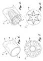
- FIG. 6is a perspective view of an exemplary embodiment of the distal end portion of the aspiration catheter shown in FIG. 1;
- FIG. 7is an end view of an alternative embodiment of the aspiration catheter in accordance with aspects of the present invention.
- FIG. 8is a perspective view of a distal end portion of an alternative embodiment of the aspiration catheter illustrating a contoured inner tapered portion
- FIG. 9is an end view of an alternative embodiment of the aspiration catheter illustrating a different cross-sectional geometry of the aspiration mouth.
- FIG. 1illustrates an exemplary embodiment of an ablation burr system 20 within an occluded vessel V, such as an SVG, having a lesion L in it.
- the ablation system 20comprises an atherectomy device 22 and an aspiration catheter 24 , each routed to a position just proximal to the lesion L to ablate and remove the lesion L so that the blood flow through the vessel V is adequately restored.
- the atherectomy device 22includes a flexible driveshaft 26 coupled to an ablation burr 28 .
- the flexible driveshaft 26has a lumen 30 extending therethrough to receive a guide wire 34 , as shown.
- the driveshaft 26is coupled at its proximal end to a source of rotational motion such as an electric motor or gas turbine (not shown) that rotates the driveshaft at high speeds, e.g., between 20,000 and 250,000 rpm.
- a source of rotational motionsuch as an electric motor or gas turbine (not shown) that rotates the driveshaft at high speeds, e.g., between 20,000 and 250,000 rpm.
- the guide wire 34is percutaneously inserted through the vasculature of a patient, and past the site of the lesion L.
- the atherectomy device 22is then routed to a point near the site of lesion L over the guide wire 34 by an advancer, not shown but well known in the art.
- a guide catheter 36shown in FIGS. 4 and 5, may be used to assist in the positioning of both the guide wire 34 and the atherectomy device 22 , also known in the art.
- Extending through the guide catheter 36is the aspiration catheter or sheath 24 for aspirating loose particulate 40 that breaks off during ablation.
- the ablation burr 28when rotated by the driveshaft 26 , ablates a new lumen through the lesion L in order to permit blood to flow freely through the vessel V.
- the aspiration catheter 24due to the presence of a vacuum or negative pressure, removes the loose particulate 40 from within the vessel.
- the atherectomy device 22 of the ablation system 20preferably comprises a flexible driveshaft 26 coupled to an ablation burr 28 , wherein the flexible driveshaft 26 and the ablation burr 28 are disposed about a central axis.
- the ablation burr 28is preferably constructed from a metallic material such as brass, and is shaped to have a generally concave front or leading surface 42 and a generally frusto-conical rear or trailing surface 44 .
- the concave front surface 42extends from an inner circumferential rim or edge portion 46 at the distal tip of the burr 28 to a ridge or crest 48 disposed approximately at the midpoint of the burr 28 .
- the frusto-conical rear surface 44extends from an inner circumferential rim or edge portion 50 at the proximal tip of the burr 28 to the ridge 48 . Accordingly, the ridge 48 has an outer diameter greater than either inner circumferential edge portions 46 , 50 .
- an axial socket 52is disposed along the central axis and extends through the frusto-conical rear surface region of the burr 28 for receiving the end of the driveshaft 26 .
- the ablation burr 28further includes a guide wire lumen 54 concentric with but having a smaller diameter than the axial socket 52 .
- the guide wire lumen 54extends from the distal end of the axial socket 52 , through the concave front surface 42 , and terminates at the distal end of the ablation burr 28 so that the ablation burr 28 may be threaded over guide wire 34 .
- the front surface 42 of the burris concave in cross section and is partially or totally covered with an abrasive material 58 such as diamond grit to ablate the lesion L when the burr is rotated.
- the frusto-conical shaped rear surface 44 of the burris also totally or partially covered with an abrasive material 60 such as diamond grit, the purpose of which is discussed in more detail below.
- the abrasive material 58 , 60can be secured on the outer surfaces 42 , 44 , of the burr by any conventional method such as electro and/or electroless plating.
- a smooth or non-abrasive portion 62 of the burr having a non-abrasive surfaceis preferably formed between the abrasive material 58 , 60 , found at the distal end and proximal ends of the burr.
- the non-abrasive portion 62preferably begins at a point of maximum diameter of the burr and continues proximally along a portion of the rear surface 44 of the burr in order to reduce irritation at the vessel walls.
- the aspiration catheter 24is routed to a position just proximal to the site of the lesion adjacent to the ablation burr so that the catheter 24 can aspirate or remove the loose particulate that might be broken off by the ablation burr.
- the aspiration catheter 24is in fluid communication with a vacuum source (not shown) such as a vacuum pump or bottle as is know in the art. It will be appreciated that other devices (not shown) may be used in conjunction with vacuum source such as a blood filter and pump to return the aspirated blood to the patient.
- the aspiration catheter 24has an elongate body of a generally cylindrical shape and includes a centrally located lumen 80 so that the driveshaft 26 can extend therethrough.
- the lumen 80also provides an conduit for loose particulate to be removed from the vessel.
- the centrally located lumen 80is concentric with the driveshaft 26 and is separated into two portions having different inner geometries.
- the two portionsconsist of a generally constant inner diameter proximal portion 82 and a generally conical distal portion 84 .
- the distal portion 84 of the lumen 80is positioned approximately at the distal end of the catheter 24 and defines an aspiration mouth 86 for receiving the loose particulate as vacuum or negative pressure is supplied to the catheter 24 via the centrally located lumen 80 .
- the distal portion 84narrows from the distal end of the catheter 24 toward the proximal end of the catheter 24 in an inwardly tapered manner to form a generally conical inner surface 90 .
- the taper of the inner surface 90 of the catheter 24generally corresponds to the taper of the rear surface 44 of the ablation burr 28 , as best shown in FIGS. 4 and 5, so that the ablation burr may be pulled back into the distal portion 84 of the lumen 80 during operation of the ablation burr system 20 .
- the diameter of the aspiration mouth 86is substantially equal to the diameter formed by the generally constant inner diameter proximal portion 82 .
- the constant inner diameter portion 82extends from the proximal end of the aspiration catheter 24 toward the distal end of the aspiration catheter 24 .
- a small, generally cylindrical lumen 88 having a substantially constant diametermay connect the proximal and distal portions 82 , 84 to provide an integral lumen 80 extending through the catheter 24 .
- the inner surface 90 of the aspiration catheter 24may be suitably contoured or textured to help grab or retain the loose particulate within the catheter 24 .
- a plurality of elongate ribs or splines 92may be positioned around the inner surface 90 of the aspiration catheter 24 to hold the loose particulate, as shown in FIGS. 7 and 8.
- the aspiration mouth 86may have a different cross-sectional geometry, such as a star-shaped opening shown in FIG. 9 which can act as a filter to collect the loose particulate at or near the mouth 86 of the aspiration catheter 24 . While the embodiments shown are exemplary of suggested configurations, it will be readily apparent to those skilled in the art that any one of a variety of suitable inner surface textures or aspiration mouth geometric openings are within the scope of the present invention.
- the ablation burr 28is routed over the guide wire 34 to the site of the lesion L.
- the aspiration catheter 24is then routed to just proximal the ablation burr 28 .
- the ablation burr 28is spun up to speed by the driveshaft 26 , which is rotated by rotational means such as a gas turbine or an electric motor.
- rotational meanssuch as a gas turbine or an electric motor.
- the burr 28is advanced through the lesion L by the advancer (not shown), whereby the abrasive 58 positioned on the front surface 42 of the burr 28 ablates the lesion L.
- the ablation burr 28may be pulled back by the advancer toward the mouth 86 of the aspiration catheter 24 . Due to the tapered rear surface 44 of the ablation burr 28 , the ablation burr 28 may be pulled into the mouth 86 of the aspiration catheter 24 .
- the ablation burr 28still rotating via the driveshaft 26 , ablates or breaks up the loose particulate 40 trapped within the aspiration catheter 24 due to the abrasive material 60 disposed on the rear surface 44 of the ablation burr 28 .
- the loose particulate 40is broken up into suitable dimensioned pieces 94 by the ablation burr 28 so that it may be removed by the aspiration catheter 24 .
- the aspiration catheterneed not have a frusto-conically-shaped lumen at its distal end.
- Other shapes that both trap ablated particles between the lumen walls and the driveshaft as well as cooperate with the rear of the burr to clear the cathetercould be used. Such shapes could be cylindrical, ovoidal, etc.
- the rear surface of the ablation burrcould include a number of blades that fit within the distal end of the aspiration catheter to clear trapped particles. If the catheter has a star-shaped or slotted lumen, as shown in FIGS.
- the rear surface of the burrmay have a corresponding shape to clear the entrance to the catheter.
- Such shapesmay be like a key such that they fit within the catheter when the burr is not rotating. It is therefore intended that the scope of the invention be determined from the following claims and equivalents thereof.
Landscapes
- Health & Medical Sciences (AREA)
- Surgery (AREA)
- Life Sciences & Earth Sciences (AREA)
- Biomedical Technology (AREA)
- Nuclear Medicine, Radiotherapy & Molecular Imaging (AREA)
- Engineering & Computer Science (AREA)
- Vascular Medicine (AREA)
- Heart & Thoracic Surgery (AREA)
- Medical Informatics (AREA)
- Molecular Biology (AREA)
- Animal Behavior & Ethology (AREA)
- General Health & Medical Sciences (AREA)
- Public Health (AREA)
- Veterinary Medicine (AREA)
- Surgical Instruments (AREA)
Abstract
Description
The present invention generally relates to devices for removing undesirable deposits from the lumen of a blood vessel or from a stent positioned within a blood vessel, and more particularly, to atherectomy devices.
Vascular diseases, such as atherosclerosis and the like, have become quite prevalent in the modern day. These diseases may present themselves in a number of forms. Each form of vascular disease may require a different method of treatment to reduce or cure the harmful effects of the disease. Vascular diseases, for example, may take the form of deposits or growths in a patient's vasculature which may restrict, in the case of a partial occlusion, or stop, in the case of a total occlusion, blood flow to a certain portion of the patient's body. This can be particularly serious if, for example, such an occlusion occurs in a portion of the vasculature that supplies vital organs with blood or other necessary fluids.
To treat these diseases, a number of different therapies are being developed. While a number of invasive therapies are available, it is desirable to develop noninvasive therapies as well. Non-invasive therapies may be less risky than invasive ones, and may be more welcomed by the patient because of the possibility of decreased chances of infection, reduced post-operative pain, and less post-operative rehabilitation. One type of non-invasive therapy for vascular diseases is pharmaceutical in nature. Clot-busting drugs have been employed to help break up blood clots, which may be blocking a particular vascular lumen. Other drug therapies are also available. Further non-invasive, intravascular treatments exist that are not only pharmaceutical, but also revascularize blood vessels or lumens by mechanical means. Two examples of such intravascular therapies are balloon angioplasty and atherectomy that physically revascularize a portion of a patient's vasculature.
Balloon angioplasty comprises a procedure wherein a balloon catheter is inserted intravascularly into a patient through a relatively small puncture, which may be located proximate the groin, and intravascularly navigated by a treating physician to the occluded vascular site. The balloon catheter includes a balloon or dilating member that is placed adjacent the vascular occlusion and then is inflated. Intravascular inflation of the dilating member by sufficient pressures, on the order of 5 to 12 atmospheres or so, causes the balloon to displace the occluding matter to revascularize the occluded lumen and thereby restore substantially normal blood flow through the revascularized portion of the vasculature. It is to be noted, however, that this procedure does not remove the occluding matter from the patient's vasculature, but displaces and reforms it.
While balloon angioplasty is quite successful in substantially revascularizing many vascular lumens by reforming the occluding material, other occlusions may be difficult to treat with angioplasty. Specifically, some intravascular occlusions may be composed of an irregular, loose or heavily calcified material which may extend relatively far along a vessel or may extend adjacent a side branching vessel, and thus are not prone or susceptible to angioplastic treatment. Even if angioplasty is successful, thereby revascularizing the vessel and substantially restoring normal blood flow therethrough, there is a chance that the occlusion may recur. Recurrence of an occlusion may require repeated or alternative treatments given at the same intravascular site.
A relatively new technique to reduce the recurrence of occlusion after a balloon angioplasty procedure involves providing a stent at the revascularized site. A stent is a hollow tube, typically braided, that can be inserted into the vasculature of a patient in a compressed form. Once properly positioned at a desired site, the stent is expanded to hold the vessel open in an attempt to prevent restenosis. While this technique can help maintain blood flow past the site, it has been found that the occluding material often migrates through the interstices of the stent braid, and may again occlude the vessel. This phenomenon is sometimes referred to as interstitial hyperplasia.
Accordingly, attempts have been made to develop other alternative mechanical methods of non-invasive, intravascular treatment in an effort to provide another way of revascularizing an occluded vessel and of restoring blood flow through the relevant vasculature. These alternative treatments may have particular utility with certain vascular occlusions, or may provide added benefits to a patient when combined with balloon angioplasty and/or drug therapies.
One such alternative mechanical treatment method involves removal, not displacement, as is the case with balloon angioplasty, of the material occluding a vascular lumen. Such treatment devices, sometimes referred to as atherectomy devices, use a variety of means, such as rotating cutters or ablaters, for example, to remove the occluding material. The rotating cutters may be particularly useful in removing certain vascular occlusions.
In operation, an atherectomy device is typically advanced over a guide wire placed in vivo until the device is positioned just proximal to the occluded site. A motor is used to rotate a driveshaft coupled to the device, and the device is moved through the occluded vessel. Frequently, an aspiration device is utilized in conjunction with the device to remove the loose particulate broken off by the device so that the particulate is not introduced into the body. Typically, a conventional aspiration device consists of a catheter in fluid communication with a vacuum source or negative pressure such as a vacuum pump or bottle. The catheter, generally surrounding the driveshaft, is advanced to the occlusion site over the guide wire to remove the loose particulate.
However, problems can occur when treating various vessels of the patient. For example, in saphenous vein grafts (SVG) and with stented vessels, the occluding material or gromous has a tendency to be more loosely organized and brittle, which makes the material friable. Therefore, in operation, conventional devices tend to break off large pieces of this material rather easily due to its morphology, instead of ablating it. These large particulate are then sucked into the mouth of the aspirating catheter, causing the loose particulate to become lodged in the mouth of the catheter. As a result, the occlusion site is presented with a lack of vacuum pressure that could hinder the aspiration process.
Therefore, there exists a need for an improved ablation burr system and process for removal of large, liberated particulate within an occluded blood vessel to overcome the deficiencies in the prior art.
An ablation system is provided to overcome the deficiencies in the prior art. The ablation system comprises an atherectomy device and an aspiration catheter, each routed to a position just proximal to a lesion within a patient's vessel to ablate and remove the lesion so that blood flow through the vessel is adequately restored.
In one embodiment of the invention, an ablation system includes a driveshaft, an ablation burr coupled to the driveshaft and an aspiration catheter. The aspiration catheter has a trap for collecting particles of occluding matter that are ablated by the burr.
In accordance with another aspect of the present invention, a mechanism is provided that cooperates with the trap on the aspiration catheter to clear collected particles from the trap.
In accordance with yet another aspect of the present invention, a system for ablating an occlusion in a patient's vessel comprises an ablation burr having a front surface and a rear surface, and being rotatable to ablate the occlusion. The system also comprises an aspiration catheter having proximal and distal ends. The catheter includes a lumen that extends longitudinally therethrough. The lumen forms an aspiration mouth at the distal end of the aspiration catheter, where the aspiration catheter includes a tapered inner surface defining a portion of the lumen.
In accordance with still another aspect of the present invention, a method is provided for ablating a lesion in a patient's vessel using an ablation burr system. An atherectomy burr is routed to a position just proximal to the lesion, the burr having a downwardly tapering rear surface. An aspiration catheter is routed to a position just proximal to the burr, the aspiration catheter having proximal and distal ends and including a lumen that extends longitudinally therethrough. The lumen forms an aspiration mouth at the distal end of the aspiration catheter, where the aspiration catheter includes a tapered inner surface defining a portion of the lumen. The burr is advanced distally through the lesion causing loose particulate to separate from the vessel wall. The loose particulate is aspirated with the aspiration catheter. The aspiration mouth of the aspiration catheter is cleared by pulling the burr proximally toward the aspiration catheter so that the burr can break down the loose particulate for removal by the catheter.
The foregoing aspects and many of the attendant advantages of this invention will become more readily appreciated as the same become better understood by reference to the following detailed description, when taken in conjunction with the accompanying drawings, wherein:
FIG. 1 is a side elevation view of an exemplary embodiment of an ablation burr system within an occluded vessel in accordance with aspects of the present invention;
FIG. 2 is a partial cross-sectional view of an exemplary embodiment of an atherectomy device shown in FIG. 1;
FIG. 3 is a partial cross-section view of an exemplary embodiment of an aspiration catheter shown in FIG. 1;
FIG. 4 is a cross-sectional view of the exemplary embodiment of the ablation burr system shown in FIG. 1 wherein the atherectomy device is advanced away from the aspiration catheter;
FIG. 5 is a cross-section view of an exemplary embodiment of the ablation burr system shown in FIG. 1 wherein the atherectomy device is pulled proximally toward and within the aspiration catheter;
FIG. 6 is a perspective view of an exemplary embodiment of the distal end portion of the aspiration catheter shown in FIG. 1;
FIG. 7 is an end view of an alternative embodiment of the aspiration catheter in accordance with aspects of the present invention;
FIG. 8 is a perspective view of a distal end portion of an alternative embodiment of the aspiration catheter illustrating a contoured inner tapered portion; and
FIG. 9 is an end view of an alternative embodiment of the aspiration catheter illustrating a different cross-sectional geometry of the aspiration mouth.
FIG. 1 illustrates an exemplary embodiment of anablation burr system 20 within an occluded vessel V, such as an SVG, having a lesion L in it. Theablation system 20 comprises anatherectomy device 22 and anaspiration catheter 24, each routed to a position just proximal to the lesion L to ablate and remove the lesion L so that the blood flow through the vessel V is adequately restored.
Referring now to FIG. 2, theatherectomy device 22 includes aflexible driveshaft 26 coupled to anablation burr 28. Theflexible driveshaft 26 has alumen 30 extending therethrough to receive aguide wire 34, as shown. Thedriveshaft 26 is coupled at its proximal end to a source of rotational motion such as an electric motor or gas turbine (not shown) that rotates the driveshaft at high speeds, e.g., between 20,000 and 250,000 rpm. In operation, with reference to FIGS. 1 and 2, theguide wire 34 is percutaneously inserted through the vasculature of a patient, and past the site of the lesion L. Theatherectomy device 22 is then routed to a point near the site of lesion L over theguide wire 34 by an advancer, not shown but well known in the art. Aguide catheter 36, shown in FIGS. 4 and 5, may be used to assist in the positioning of both theguide wire 34 and theatherectomy device 22, also known in the art. Extending through theguide catheter 36 is the aspiration catheter orsheath 24 for aspirating loose particulate40 that breaks off during ablation. Theablation burr 28, when rotated by thedriveshaft 26, ablates a new lumen through the lesion L in order to permit blood to flow freely through the vessel V. Theaspiration catheter 24, due to the presence of a vacuum or negative pressure, removes the loose particulate40 from within the vessel.
Referring to the exemplary embodiment of the present invention shown in FIG. 2, theatherectomy device 22 of theablation system 20 preferably comprises aflexible driveshaft 26 coupled to anablation burr 28, wherein theflexible driveshaft 26 and theablation burr 28 are disposed about a central axis. Theablation burr 28 is preferably constructed from a metallic material such as brass, and is shaped to have a generally concave front or leadingsurface 42 and a generally frusto-conical rear or trailingsurface 44. In the embodiment shown, the concavefront surface 42 extends from an inner circumferential rim oredge portion 46 at the distal tip of theburr 28 to a ridge orcrest 48 disposed approximately at the midpoint of theburr 28. The frusto-conicalrear surface 44 extends from an inner circumferential rim oredge portion 50 at the proximal tip of theburr 28 to theridge 48. Accordingly, theridge 48 has an outer diameter greater than either innercircumferential edge portions
As shown in FIG. 2, anaxial socket 52 is disposed along the central axis and extends through the frusto-conical rear surface region of theburr 28 for receiving the end of thedriveshaft 26. Theablation burr 28 further includes aguide wire lumen 54 concentric with but having a smaller diameter than theaxial socket 52. Theguide wire lumen 54 extends from the distal end of theaxial socket 52, through the concavefront surface 42, and terminates at the distal end of theablation burr 28 so that theablation burr 28 may be threaded overguide wire 34.
As indicated above, thefront surface 42 of the burr is concave in cross section and is partially or totally covered with anabrasive material 58 such as diamond grit to ablate the lesion L when the burr is rotated. The frusto-conical shapedrear surface 44 of the burr is also totally or partially covered with anabrasive material 60 such as diamond grit, the purpose of which is discussed in more detail below. Theabrasive material outer surfaces non-abrasive portion 62 of the burr having a non-abrasive surface is preferably formed between theabrasive material non-abrasive portion 62 preferably begins at a point of maximum diameter of the burr and continues proximally along a portion of therear surface 44 of the burr in order to reduce irritation at the vessel walls.
Referring now to FIG. 3, theaspiration catheter 24 is routed to a position just proximal to the site of the lesion adjacent to the ablation burr so that thecatheter 24 can aspirate or remove the loose particulate that might be broken off by the ablation burr. Theaspiration catheter 24 is in fluid communication with a vacuum source (not shown) such as a vacuum pump or bottle as is know in the art. It will be appreciated that other devices (not shown) may be used in conjunction with vacuum source such as a blood filter and pump to return the aspirated blood to the patient. Theaspiration catheter 24 has an elongate body of a generally cylindrical shape and includes a centrally locatedlumen 80 so that thedriveshaft 26 can extend therethrough. Thelumen 80 also provides an conduit for loose particulate to be removed from the vessel.
As shown in FIGS. 3 and 6, the centrally locatedlumen 80 is concentric with thedriveshaft 26 and is separated into two portions having different inner geometries. The two portions consist of a generally constant inner diameterproximal portion 82 and a generally conicaldistal portion 84. Thedistal portion 84 of thelumen 80 is positioned approximately at the distal end of thecatheter 24 and defines anaspiration mouth 86 for receiving the loose particulate as vacuum or negative pressure is supplied to thecatheter 24 via the centrally locatedlumen 80. Thedistal portion 84 narrows from the distal end of thecatheter 24 toward the proximal end of thecatheter 24 in an inwardly tapered manner to form a generally conicalinner surface 90. The taper of theinner surface 90 of thecatheter 24 generally corresponds to the taper of therear surface 44 of theablation burr 28, as best shown in FIGS. 4 and 5, so that the ablation burr may be pulled back into thedistal portion 84 of thelumen 80 during operation of theablation burr system 20.
In the embodiment shown, the diameter of theaspiration mouth 86 is substantially equal to the diameter formed by the generally constant inner diameterproximal portion 82. The constantinner diameter portion 82 extends from the proximal end of theaspiration catheter 24 toward the distal end of theaspiration catheter 24. A small, generallycylindrical lumen 88 having a substantially constant diameter may connect the proximal anddistal portions integral lumen 80 extending through thecatheter 24.
Theinner surface 90 of theaspiration catheter 24 may be suitably contoured or textured to help grab or retain the loose particulate within thecatheter 24. For example, a plurality of elongate ribs or splines92 may be positioned around theinner surface 90 of theaspiration catheter 24 to hold the loose particulate, as shown in FIGS. 7 and 8. Alternatively, theaspiration mouth 86 may have a different cross-sectional geometry, such as a star-shaped opening shown in FIG. 9 which can act as a filter to collect the loose particulate at or near themouth 86 of theaspiration catheter 24. While the embodiments shown are exemplary of suggested configurations, it will be readily apparent to those skilled in the art that any one of a variety of suitable inner surface textures or aspiration mouth geometric openings are within the scope of the present invention.
The operation of the ablation system constructed in accordance with aspects of the present invention will now be described with reference to FIGS. 1,4 and5. Theablation burr 28 is routed over theguide wire 34 to the site of the lesion L. Theaspiration catheter 24 is then routed to just proximal theablation burr 28. Theablation burr 28 is spun up to speed by thedriveshaft 26, which is rotated by rotational means such as a gas turbine or an electric motor. As theburr 28 is rotated, theburr 28 is advanced through the lesion L by the advancer (not shown), whereby the abrasive58 positioned on thefront surface 42 of theburr 28 ablates the lesion L. During the ablation procedure, loose particulate40 that was not completely ablated is detached from the vessel wall and remains suspended within the blood of the vessel V. A slight vacuum present at themouth 86 of theaspiration catheter 24 pulls theloose particulate 40 within themouth 86 of thecatheter 24. Due to the presence of the frusto-conicalinner surface 90 within themouth 86 of thecatheter 24, large pieces of theloose particulate 40 are trapped between thedriveshaft 26 and the frusto-conicalinner surface 90 of theaspiration catheter 24.
After the lesion L is fully ablated or when the physician notices a drop in aspiration pressure, theablation burr 28 may be pulled back by the advancer toward themouth 86 of theaspiration catheter 24. Due to the taperedrear surface 44 of theablation burr 28, theablation burr 28 may be pulled into themouth 86 of theaspiration catheter 24. Theablation burr 28, still rotating via thedriveshaft 26, ablates or breaks up theloose particulate 40 trapped within theaspiration catheter 24 due to theabrasive material 60 disposed on therear surface 44 of theablation burr 28. Theloose particulate 40 is broken up into suitable dimensionedpieces 94 by theablation burr 28 so that it may be removed by theaspiration catheter 24.
While the preferred embodiment of the invention has been illustrated and described, it will be appreciated that various changes can be made therein without departing from the scope of the invention. For example, the aspiration catheter need not have a frusto-conically-shaped lumen at its distal end. Other shapes that both trap ablated particles between the lumen walls and the driveshaft as well as cooperate with the rear of the burr to clear the catheter could be used. Such shapes could be cylindrical, ovoidal, etc. Similarly, the rear surface of the ablation burr could include a number of blades that fit within the distal end of the aspiration catheter to clear trapped particles. If the catheter has a star-shaped or slotted lumen, as shown in FIGS. 7-9, then the rear surface of the burr may have a corresponding shape to clear the entrance to the catheter. Such shapes may be like a key such that they fit within the catheter when the burr is not rotating. It is therefore intended that the scope of the invention be determined from the following claims and equivalents thereof.
Claims (7)
1. An aspiration catheter for use in an ablation system, the ablation system operable for removing lesion material from a patient's vasculature, comprising:
an elongate body having proximal and distal ends and including inner side walls that define a lumen and a filter section at its distal end;
wherein said lumen has a first cross-sectional area and said filter section has a distal opening with a second cross-section area at said distal end of said elongate body and a proximal opening with a third cross-sectional area positioned proximal to said distal opening, wherein said cross-sectional area of said proximal opening of said filter section is smaller than said cross-sectional area of said lumen and said cross-sectional area of said distal end of said filter section.
2. The catheter ofclaim 1 , wherein said inner walls of said filter section are contoured.
3. The catheter ofclaim 1 , wherein said contoured side walls of said filter section include longitudinally extending splines.
4. The catheter ofclaim 1 , wherein said aspiration mouth forms a star shaped opening.
5. A method for ablating a lesion in a patient's vessel using an ablation burr system comprising:
routing an atherectomy burr that is connected to a driveshaft over a guidewire to a position just proximate to said lesion, said burr having a proximal surface;
routing an aspiration catheter over the driveshaft to a position just proximate to said burr, said aspiration catheter having proximal and distal ends and including a lumen extending longitudinally therethrough, said lumen forming an aspiration mouth at said distal end of said aspiration catheter, wherein said aspiration catheter includes a filter section defining a portion of said lumen that cooperates with said proximal surface of said burr;
rotating and advancing said burr distally through said lesion causing loose lesion particulate to separate from the vessel wall;
aspirating said loose lesion particulate with said aspiration catheter;
filtering at least some of said loose lesion particulate by trapping said loose lesion particulate in said filter section; and
clearing said filter section from said trapped lesion particulate by moving said rotating burr toward said aspiration catheter and into engagement with said trapped lesion particulate so that said proximal surface of the burr breaks down said trapped lesion particulate for removal by said catheter.
6. The method ofclaim 5 , wherein clearing said aspiration mouth of said aspiration catheter occurs during the atherectomy process when a loss in aspiration pressure is determined.
7. The method ofclaim 5 , wherein clearing said aspiration mouth of said aspiration catheter occurs after the lesion has been fully removed and the blood flow through the vessel has been restored.
Priority Applications (3)
| Application Number | Priority Date | Filing Date | Title |
|---|---|---|---|
| US09/835,130US6632230B2 (en) | 2001-04-12 | 2001-04-12 | Ablation system with catheter clearing abrasive |
| PCT/US2002/010200WO2002083226A2 (en) | 2001-04-12 | 2002-03-27 | Ablation system with catheter clearing abrasive |
| AU2002250492AAU2002250492A1 (en) | 2001-04-12 | 2002-03-27 | Ablation system with catheter clearing abrasive |
Applications Claiming Priority (1)
| Application Number | Priority Date | Filing Date | Title |
|---|---|---|---|
| US09/835,130US6632230B2 (en) | 2001-04-12 | 2001-04-12 | Ablation system with catheter clearing abrasive |
Publications (2)
| Publication Number | Publication Date |
|---|---|
| US20020151917A1 US20020151917A1 (en) | 2002-10-17 |
| US6632230B2true US6632230B2 (en) | 2003-10-14 |
Family
ID=25268659
Family Applications (1)
| Application Number | Title | Priority Date | Filing Date |
|---|---|---|---|
| US09/835,130Expired - LifetimeUS6632230B2 (en) | 2001-04-12 | 2001-04-12 | Ablation system with catheter clearing abrasive |
Country Status (3)
| Country | Link |
|---|---|
| US (1) | US6632230B2 (en) |
| AU (1) | AU2002250492A1 (en) |
| WO (1) | WO2002083226A2 (en) |
Cited By (36)
| Publication number | Priority date | Publication date | Assignee | Title |
|---|---|---|---|---|
| US20060189971A1 (en)* | 1995-11-22 | 2006-08-24 | Arthrocare Corporation | Systems and methods for electrosurgical treatment of fasciitis |
| US7179269B2 (en) | 2002-05-20 | 2007-02-20 | Scimed Life Systems, Inc. | Apparatus and system for removing an obstruction from a lumen |
| US7326226B2 (en) | 1999-08-04 | 2008-02-05 | Boston Scientific Scimed, Inc. | Percutaneous catheter and guidewire for filtering during ablation of myocardial or vascular tissue |
| US20100030186A1 (en)* | 2008-07-31 | 2010-02-04 | Boston Scientific Scimed, Inc. | Extendable aspiration catheter |
| US20100042095A1 (en)* | 2008-08-13 | 2010-02-18 | Robert Bigley | Systems and methods for screen electrode securement |
| US7819863B2 (en) | 1992-01-07 | 2010-10-26 | Arthrocare Corporation | System and method for electrosurgical cutting and ablation |
| US8012153B2 (en) | 2003-07-16 | 2011-09-06 | Arthrocare Corporation | Rotary electrosurgical apparatus and methods thereof |
| US20110218560A1 (en)* | 2003-09-17 | 2011-09-08 | Stryker Corporation | Embolectomy device |
| US8317786B2 (en) | 2009-09-25 | 2012-11-27 | AthroCare Corporation | System, method and apparatus for electrosurgical instrument with movable suction sheath |
| US8323279B2 (en) | 2009-09-25 | 2012-12-04 | Arthocare Corporation | System, method and apparatus for electrosurgical instrument with movable fluid delivery sheath |
| US8355799B2 (en) | 2008-12-12 | 2013-01-15 | Arthrocare Corporation | Systems and methods for limiting joint temperature |
| US8663216B2 (en) | 1998-08-11 | 2014-03-04 | Paul O. Davison | Instrument for electrosurgical tissue treatment |
| US8663259B2 (en) | 2010-05-13 | 2014-03-04 | Rex Medical L.P. | Rotational thrombectomy wire |
| US8696659B2 (en) | 2010-04-30 | 2014-04-15 | Arthrocare Corporation | Electrosurgical system and method having enhanced temperature measurement |
| US8764779B2 (en) | 2010-05-13 | 2014-07-01 | Rex Medical, L.P. | Rotational thrombectomy wire |
| US9023070B2 (en) | 2010-05-13 | 2015-05-05 | Rex Medical, L.P. | Rotational thrombectomy wire coupler |
| US9055951B2 (en) | 2011-05-23 | 2015-06-16 | Covidien Lp | Endovascular tissue removal device |
| US9056191B2 (en) | 2012-04-11 | 2015-06-16 | Covidien Lp | Apparatus and method for removing occlusive tissue |
| US9526556B2 (en) | 2014-02-28 | 2016-12-27 | Arthrocare Corporation | Systems and methods systems related to electrosurgical wands with screen electrodes |
| US9597142B2 (en) | 2014-07-24 | 2017-03-21 | Arthrocare Corporation | Method and system related to electrosurgical procedures |
| US9649148B2 (en) | 2014-07-24 | 2017-05-16 | Arthrocare Corporation | Electrosurgical system and method having enhanced arc prevention |
| US9795406B2 (en) | 2010-05-13 | 2017-10-24 | Rex Medical, L.P. | Rotational thrombectomy wire |
| US10271869B2 (en) | 2014-03-01 | 2019-04-30 | Rex Medical, L.P. | Atherectomy device |
| US10307175B2 (en) | 2016-03-26 | 2019-06-04 | Rex Medical, L.P | Atherectomy device |
| US10433868B2 (en) | 2014-12-27 | 2019-10-08 | Rex Medical, L.P. | Artherectomy device |
| US10463389B2 (en) | 2014-12-27 | 2019-11-05 | Rex Medical, L.P. | Atherectomy device |
| US10869689B2 (en) | 2017-05-03 | 2020-12-22 | Medtronic Vascular, Inc. | Tissue-removing catheter |
| US11096716B2 (en)* | 2018-02-15 | 2021-08-24 | Boston Scientific Scimed, Inc. | Atherectomy medical device |
| US11253292B2 (en) | 2015-09-13 | 2022-02-22 | Rex Medical, L.P. | Atherectomy device |
| US11357534B2 (en) | 2018-11-16 | 2022-06-14 | Medtronic Vascular, Inc. | Catheter |
| US20220211409A1 (en)* | 2019-05-17 | 2022-07-07 | Koninklijke Philips N.V. | Atherectomy devices including positive and negative rake angle cutting blades |
| US11406419B2 (en)* | 2018-10-29 | 2022-08-09 | Cardiovascular Systems, Inc. | System, device, and method for interrupted dual action (sanding and cutting) forces with continual maceration and aspiration |
| US11419628B2 (en) | 2018-09-10 | 2022-08-23 | Medtronic Vascular, Inc. | Tissue-removing catheter with guidewire detection sensor |
| US11690645B2 (en) | 2017-05-03 | 2023-07-04 | Medtronic Vascular, Inc. | Tissue-removing catheter |
| US11819236B2 (en) | 2019-05-17 | 2023-11-21 | Medtronic Vascular, Inc. | Tissue-removing catheter |
| US12171457B2 (en) | 2020-10-30 | 2024-12-24 | Boston Scientific Scimed, Inc. | Atherectomy burrs with blood flow enhancements |
Families Citing this family (32)
| Publication number | Priority date | Publication date | Assignee | Title |
|---|---|---|---|---|
| US9433457B2 (en) | 2000-12-09 | 2016-09-06 | Tsunami Medtech, Llc | Medical instruments and techniques for thermally-mediated therapies |
| US8444636B2 (en) | 2001-12-07 | 2013-05-21 | Tsunami Medtech, Llc | Medical instrument and method of use |
| US8579892B2 (en) | 2003-10-07 | 2013-11-12 | Tsunami Medtech, Llc | Medical system and method of use |
| US20060217739A1 (en)* | 2005-03-22 | 2006-09-28 | Alcon, Inc. | Phacoemulsification tip |
| EP2190373B1 (en) | 2007-08-23 | 2013-01-09 | Aegea Medical, Inc. | Uterine therapy device |
| US9924992B2 (en) | 2008-02-20 | 2018-03-27 | Tsunami Medtech, Llc | Medical system and method of use |
| US8721632B2 (en) | 2008-09-09 | 2014-05-13 | Tsunami Medtech, Llc | Methods for delivering energy into a target tissue of a body |
| US20100204690A1 (en)* | 2008-08-13 | 2010-08-12 | Arthrocare Corporation | Single aperture electrode assembly |
| US8308735B2 (en)* | 2008-10-06 | 2012-11-13 | Novartis Ag | Phacoemulsification tip with internal oriented structures |
| US11284931B2 (en) | 2009-02-03 | 2022-03-29 | Tsunami Medtech, Llc | Medical systems and methods for ablating and absorbing tissue |
| GB2473806B (en)* | 2009-07-22 | 2011-08-10 | Cook William Europ | Aspiration catheter |
| GB2488267B (en)* | 2009-12-07 | 2016-06-08 | Arthrocare Corp | Single aperture electrode assembly |
| US9161801B2 (en)* | 2009-12-30 | 2015-10-20 | Tsunami Medtech, Llc | Medical system and method of use |
| US9907567B2 (en)* | 2010-05-04 | 2018-03-06 | Samuel Shiber | Mechanical — pharmaceutical system for opening obstructed bodily vessels |
| US9943353B2 (en) | 2013-03-15 | 2018-04-17 | Tsunami Medtech, Llc | Medical system and method of use |
| ES2912362T3 (en) | 2010-11-09 | 2022-05-25 | Aegea Medical Inc | Method of placement and apparatus for delivering steam to the uterus |
| CA2851355C (en) | 2011-10-07 | 2020-02-18 | Aegea Medical Inc. | Integrity testing method and apparatus for delivering vapor to the uterus |
| US10213533B2 (en)* | 2012-03-05 | 2019-02-26 | Keith A. Walter | Medical tools with aspiration tips suitable for cataract surgeries and related methods |
| US9414752B2 (en) | 2012-11-09 | 2016-08-16 | Elwha Llc | Embolism deflector |
| JP6352642B2 (en)* | 2013-12-03 | 2018-07-04 | 川澄化学工業株式会社 | Intravascular foreign body removal catheter |
| EP3145425B1 (en) | 2014-05-22 | 2024-10-23 | CooperSurgical, Inc. | Systems for performing endometrial ablation |
| US10179019B2 (en) | 2014-05-22 | 2019-01-15 | Aegea Medical Inc. | Integrity testing method and apparatus for delivering vapor to the uterus |
| EP3416551B1 (en) | 2016-02-19 | 2022-10-12 | Aegea Medical Inc. | Apparatus for determining the integrity of a bodily cavity |
| CN110520069B (en)* | 2017-03-28 | 2022-10-18 | 泰尔茂株式会社 | Medical device and treatment method |
| CN107261223B (en)* | 2017-07-19 | 2023-08-29 | 宁波市第一医院 | Intragastric blood clot drawing device |
| US11950801B2 (en)* | 2019-01-18 | 2024-04-09 | Boston Scientific Scimed, Inc. | Gearbox for atherectomy system |
| EP4192328A4 (en)* | 2020-08-05 | 2024-07-17 | Shawn P. Fojtik | MEDICAL ASPIRATION DEVICES AND METHODS |
| CN112451045B (en)* | 2020-12-16 | 2025-03-18 | 福建珞创医疗科技有限公司 | A highly efficient device for removing vascular calcified tissue and a working method thereof |
| CN113081185B (en)* | 2021-04-08 | 2022-05-10 | 哈尔滨医科大学 | Thrombus cutting system |
| WO2023069188A1 (en)* | 2021-10-20 | 2023-04-27 | Boston Scientific Scimed, Inc. | Fly by wire control for atherectomy |
| CN119055927B (en)* | 2024-08-16 | 2025-06-17 | 绵阳四〇四医院 | A navigation catheter |
| CN119074137B (en)* | 2024-10-21 | 2025-04-08 | 南京鼓楼医院 | Vascular calcified plaque cutting device |
Citations (18)
| Publication number | Priority date | Publication date | Assignee | Title |
|---|---|---|---|---|
| US4732154A (en)* | 1984-05-14 | 1988-03-22 | Surgical Systems & Instruments, Inc. | Rotary catheter system |
| US5154724A (en)* | 1990-05-14 | 1992-10-13 | Andrews Winston A | Atherectomy catheter |
| US5318576A (en)* | 1992-12-16 | 1994-06-07 | Plassche Jr Walter M | Endovascular surgery systems |
| US5507732A (en)* | 1994-10-05 | 1996-04-16 | Medtronic, Inc. | Quick assembly catheter manifold |
| US5569275A (en) | 1991-06-11 | 1996-10-29 | Microvena Corporation | Mechanical thrombus maceration device |
| US5681336A (en)* | 1995-09-07 | 1997-10-28 | Boston Scientific Corporation | Therapeutic device for treating vien graft lesions |
| US5766192A (en)* | 1995-10-20 | 1998-06-16 | Zacca; Nadim M. | Atherectomy, angioplasty and stent method and apparatus |
| US5772627A (en)* | 1996-07-19 | 1998-06-30 | Neuro Navigational Corp. | Ultrasonic tissue resector for neurosurgery |
| US5779721A (en) | 1996-07-26 | 1998-07-14 | Kensey Nash Corporation | System and method of use for revascularizing stenotic bypass grafts and other blood vessels |
| US5843103A (en)* | 1997-03-06 | 1998-12-01 | Scimed Life Systems, Inc. | Shaped wire rotational atherectomy device |
| US6001112A (en)* | 1998-04-10 | 1999-12-14 | Endicor Medical, Inc. | Rotational atherectomy device |
| US6074357A (en)* | 1996-12-05 | 2000-06-13 | Embol-X, Inc. | Cerebral protection during carotid endarterectomy and downstream vascular protection during other surgeries |
| US6129698A (en) | 1996-05-24 | 2000-10-10 | Beck; Robert C | Catheter |
| US6146395A (en)* | 1998-03-05 | 2000-11-14 | Scimed Life Systems, Inc. | Ablation burr |
| US6152913A (en)* | 1995-04-27 | 2000-11-28 | The Kippgroup | Medical luer connection having protective cap with crush rib |
| US6183487B1 (en) | 1997-03-06 | 2001-02-06 | Scimed Life Systems, Inc. | Ablation device for reducing damage to vessels and/or in-vivo stents |
| US6344049B1 (en)* | 1999-08-17 | 2002-02-05 | Scion Cardio-Vascular, Inc. | Filter for embolic material mounted on expandable frame and associated deployment system |
| US6451036B1 (en)* | 1998-04-10 | 2002-09-17 | Endicor Medical, Inc. | Rotational atherectomy system with stationary cutting elements |
- 2001
- 2001-04-12USUS09/835,130patent/US6632230B2/ennot_activeExpired - Lifetime
- 2002
- 2002-03-27AUAU2002250492Apatent/AU2002250492A1/ennot_activeAbandoned
- 2002-03-27WOPCT/US2002/010200patent/WO2002083226A2/ennot_activeApplication Discontinuation
Patent Citations (18)
| Publication number | Priority date | Publication date | Assignee | Title |
|---|---|---|---|---|
| US4732154A (en)* | 1984-05-14 | 1988-03-22 | Surgical Systems & Instruments, Inc. | Rotary catheter system |
| US5154724A (en)* | 1990-05-14 | 1992-10-13 | Andrews Winston A | Atherectomy catheter |
| US5569275A (en) | 1991-06-11 | 1996-10-29 | Microvena Corporation | Mechanical thrombus maceration device |
| US5318576A (en)* | 1992-12-16 | 1994-06-07 | Plassche Jr Walter M | Endovascular surgery systems |
| US5507732A (en)* | 1994-10-05 | 1996-04-16 | Medtronic, Inc. | Quick assembly catheter manifold |
| US6152913A (en)* | 1995-04-27 | 2000-11-28 | The Kippgroup | Medical luer connection having protective cap with crush rib |
| US5681336A (en)* | 1995-09-07 | 1997-10-28 | Boston Scientific Corporation | Therapeutic device for treating vien graft lesions |
| US5766192A (en)* | 1995-10-20 | 1998-06-16 | Zacca; Nadim M. | Atherectomy, angioplasty and stent method and apparatus |
| US6129698A (en) | 1996-05-24 | 2000-10-10 | Beck; Robert C | Catheter |
| US5772627A (en)* | 1996-07-19 | 1998-06-30 | Neuro Navigational Corp. | Ultrasonic tissue resector for neurosurgery |
| US5779721A (en) | 1996-07-26 | 1998-07-14 | Kensey Nash Corporation | System and method of use for revascularizing stenotic bypass grafts and other blood vessels |
| US6074357A (en)* | 1996-12-05 | 2000-06-13 | Embol-X, Inc. | Cerebral protection during carotid endarterectomy and downstream vascular protection during other surgeries |
| US5843103A (en)* | 1997-03-06 | 1998-12-01 | Scimed Life Systems, Inc. | Shaped wire rotational atherectomy device |
| US6183487B1 (en) | 1997-03-06 | 2001-02-06 | Scimed Life Systems, Inc. | Ablation device for reducing damage to vessels and/or in-vivo stents |
| US6146395A (en)* | 1998-03-05 | 2000-11-14 | Scimed Life Systems, Inc. | Ablation burr |
| US6001112A (en)* | 1998-04-10 | 1999-12-14 | Endicor Medical, Inc. | Rotational atherectomy device |
| US6451036B1 (en)* | 1998-04-10 | 2002-09-17 | Endicor Medical, Inc. | Rotational atherectomy system with stationary cutting elements |
| US6344049B1 (en)* | 1999-08-17 | 2002-02-05 | Scion Cardio-Vascular, Inc. | Filter for embolic material mounted on expandable frame and associated deployment system |
Cited By (58)
| Publication number | Priority date | Publication date | Assignee | Title |
|---|---|---|---|---|
| US7819863B2 (en) | 1992-01-07 | 2010-10-26 | Arthrocare Corporation | System and method for electrosurgical cutting and ablation |
| US20060189971A1 (en)* | 1995-11-22 | 2006-08-24 | Arthrocare Corporation | Systems and methods for electrosurgical treatment of fasciitis |
| US8663216B2 (en) | 1998-08-11 | 2014-03-04 | Paul O. Davison | Instrument for electrosurgical tissue treatment |
| US7326226B2 (en) | 1999-08-04 | 2008-02-05 | Boston Scientific Scimed, Inc. | Percutaneous catheter and guidewire for filtering during ablation of myocardial or vascular tissue |
| US7179269B2 (en) | 2002-05-20 | 2007-02-20 | Scimed Life Systems, Inc. | Apparatus and system for removing an obstruction from a lumen |
| US8012153B2 (en) | 2003-07-16 | 2011-09-06 | Arthrocare Corporation | Rotary electrosurgical apparatus and methods thereof |
| US20110218560A1 (en)* | 2003-09-17 | 2011-09-08 | Stryker Corporation | Embolectomy device |
| US8465456B2 (en) | 2008-07-31 | 2013-06-18 | Boston Scientific Scimed, Inc. | Extendable aspiration catheter |
| US20100030186A1 (en)* | 2008-07-31 | 2010-02-04 | Boston Scientific Scimed, Inc. | Extendable aspiration catheter |
| US8747400B2 (en) | 2008-08-13 | 2014-06-10 | Arthrocare Corporation | Systems and methods for screen electrode securement |
| US20100042095A1 (en)* | 2008-08-13 | 2010-02-18 | Robert Bigley | Systems and methods for screen electrode securement |
| US9452008B2 (en) | 2008-12-12 | 2016-09-27 | Arthrocare Corporation | Systems and methods for limiting joint temperature |
| US8355799B2 (en) | 2008-12-12 | 2013-01-15 | Arthrocare Corporation | Systems and methods for limiting joint temperature |
| US8317786B2 (en) | 2009-09-25 | 2012-11-27 | AthroCare Corporation | System, method and apparatus for electrosurgical instrument with movable suction sheath |
| US8323279B2 (en) | 2009-09-25 | 2012-12-04 | Arthocare Corporation | System, method and apparatus for electrosurgical instrument with movable fluid delivery sheath |
| US8696659B2 (en) | 2010-04-30 | 2014-04-15 | Arthrocare Corporation | Electrosurgical system and method having enhanced temperature measurement |
| US10064645B2 (en) | 2010-05-13 | 2018-09-04 | Rex Medical, L.P. | Rotational thrombectomy wire |
| US9023070B2 (en) | 2010-05-13 | 2015-05-05 | Rex Medical, L.P. | Rotational thrombectomy wire coupler |
| US9282992B2 (en) | 2010-05-13 | 2016-03-15 | Rex Medical, L.P. | Rotational thrombectomy wire |
| US8764779B2 (en) | 2010-05-13 | 2014-07-01 | Rex Medical, L.P. | Rotational thrombectomy wire |
| US10517630B2 (en) | 2010-05-13 | 2019-12-31 | Rex Medical, L.P. | Rotational thrombectomy wire |
| US8663259B2 (en) | 2010-05-13 | 2014-03-04 | Rex Medical L.P. | Rotational thrombectomy wire |
| US9700346B2 (en) | 2010-05-13 | 2017-07-11 | Rex Medical, L.P. | Rotational thrombectomy wire |
| US9795406B2 (en) | 2010-05-13 | 2017-10-24 | Rex Medical, L.P. | Rotational thrombectomy wire |
| US9055951B2 (en) | 2011-05-23 | 2015-06-16 | Covidien Lp | Endovascular tissue removal device |
| US9056191B2 (en) | 2012-04-11 | 2015-06-16 | Covidien Lp | Apparatus and method for removing occlusive tissue |
| US9526556B2 (en) | 2014-02-28 | 2016-12-27 | Arthrocare Corporation | Systems and methods systems related to electrosurgical wands with screen electrodes |
| US10271869B2 (en) | 2014-03-01 | 2019-04-30 | Rex Medical, L.P. | Atherectomy device |
| US10751083B2 (en) | 2014-03-01 | 2020-08-25 | Rex Medical L.P. | Atherectomy device |
| US9597142B2 (en) | 2014-07-24 | 2017-03-21 | Arthrocare Corporation | Method and system related to electrosurgical procedures |
| US9649148B2 (en) | 2014-07-24 | 2017-05-16 | Arthrocare Corporation | Electrosurgical system and method having enhanced arc prevention |
| US10433868B2 (en) | 2014-12-27 | 2019-10-08 | Rex Medical, L.P. | Artherectomy device |
| US10463389B2 (en) | 2014-12-27 | 2019-11-05 | Rex Medical, L.P. | Atherectomy device |
| US11547434B2 (en) | 2014-12-27 | 2023-01-10 | Rex Medical L.P. | Atherectomy device |
| US11426194B2 (en) | 2014-12-27 | 2022-08-30 | Rex Medical L.P. | Atherectomy device |
| US11253292B2 (en) | 2015-09-13 | 2022-02-22 | Rex Medical, L.P. | Atherectomy device |
| US12274822B2 (en) | 2015-09-13 | 2025-04-15 | Rex Medical, L.P. | Atherectomy device |
| US10307175B2 (en) | 2016-03-26 | 2019-06-04 | Rex Medical, L.P | Atherectomy device |
| US11864780B2 (en) | 2016-03-26 | 2024-01-09 | Rex Medical, L.P. | Atherectomy device |
| US11020134B2 (en) | 2016-03-26 | 2021-06-01 | Rex Meddical L.P. | Atherectomy device |
| US10925632B2 (en) | 2017-05-03 | 2021-02-23 | Medtronic Vascular, Inc. | Tissue-removing catheter |
| US12114887B2 (en) | 2017-05-03 | 2024-10-15 | Medtronic Vascular, Inc. | Tissue-removing catheter with guidewire isolation liner |
| US10869689B2 (en) | 2017-05-03 | 2020-12-22 | Medtronic Vascular, Inc. | Tissue-removing catheter |
| US11986207B2 (en) | 2017-05-03 | 2024-05-21 | Medtronic Vascular, Inc. | Tissue-removing catheter with guidewire isolation liner |
| US11896260B2 (en) | 2017-05-03 | 2024-02-13 | Medtronic Vascular, Inc. | Tissue-removing catheter |
| US11871958B2 (en) | 2017-05-03 | 2024-01-16 | Medtronic Vascular, Inc. | Tissue-removing catheter with guidewire isolation liner |
| US11051842B2 (en) | 2017-05-03 | 2021-07-06 | Medtronic Vascular, Inc. | Tissue-removing catheter with guidewire isolation liner |
| US11690645B2 (en) | 2017-05-03 | 2023-07-04 | Medtronic Vascular, Inc. | Tissue-removing catheter |
| US10987126B2 (en) | 2017-05-03 | 2021-04-27 | Medtronic Vascular, Inc. | Tissue-removing catheter with guidewire isolation liner |
| US11096716B2 (en)* | 2018-02-15 | 2021-08-24 | Boston Scientific Scimed, Inc. | Atherectomy medical device |
| US11419628B2 (en) | 2018-09-10 | 2022-08-23 | Medtronic Vascular, Inc. | Tissue-removing catheter with guidewire detection sensor |
| US11406419B2 (en)* | 2018-10-29 | 2022-08-09 | Cardiovascular Systems, Inc. | System, device, and method for interrupted dual action (sanding and cutting) forces with continual maceration and aspiration |
| US12171458B2 (en) | 2018-10-29 | 2024-12-24 | Cardiovascular Systems, Inc. | System, device, and method for interrupted dual action (sanding and cutting) forces with continual maceration and aspiration |
| US11357534B2 (en) | 2018-11-16 | 2022-06-14 | Medtronic Vascular, Inc. | Catheter |
| US12161359B2 (en) | 2018-11-16 | 2024-12-10 | Medtronic Vascular, Inc. | Catheter |
| US11819236B2 (en) | 2019-05-17 | 2023-11-21 | Medtronic Vascular, Inc. | Tissue-removing catheter |
| US20220211409A1 (en)* | 2019-05-17 | 2022-07-07 | Koninklijke Philips N.V. | Atherectomy devices including positive and negative rake angle cutting blades |
| US12171457B2 (en) | 2020-10-30 | 2024-12-24 | Boston Scientific Scimed, Inc. | Atherectomy burrs with blood flow enhancements |
Also Published As
| Publication number | Publication date |
|---|---|
| AU2002250492A1 (en) | 2002-10-28 |
| WO2002083226A3 (en) | 2002-12-27 |
| US20020151917A1 (en) | 2002-10-17 |
| WO2002083226A2 (en) | 2002-10-24 |
Similar Documents
| Publication | Publication Date | Title |
|---|---|---|
| US6632230B2 (en) | Ablation system with catheter clearing abrasive | |
| US6156048A (en) | Atherectomy device for reducing damage to vessels and/or in-vivo stents | |
| US6183487B1 (en) | Ablation device for reducing damage to vessels and/or in-vivo stents | |
| AU2018226388B2 (en) | Devices and systems for thrombus treatment | |
| US10751083B2 (en) | Atherectomy device | |
| US6569177B1 (en) | Ablation atherectomy burr | |
| US6579298B1 (en) | Method and apparatus for treating vein graft lesions | |
| US4886061A (en) | Expandable pullback atherectomy catheter system | |
| US7713227B2 (en) | Method and apparatus for medical device for aspiration of thromboemobolic debris | |
| CA2860301C (en) | Device and method for removing occlusions in a biological vessel | |
| EP1644069B1 (en) | Devices for aspirating from filters | |
| US7951161B2 (en) | Atherectomy system having a variably exposed cutter | |
| EP3250132B1 (en) | Device for removing occlusions in a biological vessel | |
| JPH08503154A (en) | Device and method for endovascular occlusion removal | |
| CN113855164B (en) | A mesh-disk type mechanical thrombus removal catheter device | |
| CN114423361A (en) | Atherectomy device comprising cutting blades with different edge shapes | |
| AU618331B2 (en) | Expandable pullback atherectomy catheter system | |
| US20250228587A1 (en) | Devices, systems, and methods for performing thrombectomy procedures | |
| US20250228588A1 (en) | Devices, systems, and methods for performing thrombectomy procedures |
Legal Events
| Date | Code | Title | Description |
|---|---|---|---|
| AS | Assignment | Owner name:SCIMED LIFE SYSTEMS, INC., MINNESOTA Free format text:ASSIGNMENT OF ASSIGNORS INTEREST;ASSIGNOR:BARRY, ROBERT L.;REEL/FRAME:011701/0879 Effective date:20010402 | |
| STCF | Information on status: patent grant | Free format text:PATENTED CASE | |
| CC | Certificate of correction | ||
| AS | Assignment | Owner name:BOSTON SCIENTIFIC SCIMED, INC., MINNESOTA Free format text:CHANGE OF NAME;ASSIGNOR:SCIMED LIFE SYSTEMS, INC.;REEL/FRAME:018505/0868 Effective date:20050101 Owner name:BOSTON SCIENTIFIC SCIMED, INC.,MINNESOTA Free format text:CHANGE OF NAME;ASSIGNOR:SCIMED LIFE SYSTEMS, INC.;REEL/FRAME:018505/0868 Effective date:20050101 | |
| FEPP | Fee payment procedure | Free format text:PAYOR NUMBER ASSIGNED (ORIGINAL EVENT CODE: ASPN); ENTITY STATUS OF PATENT OWNER: LARGE ENTITY | |
| FPAY | Fee payment | Year of fee payment:4 | |
| FPAY | Fee payment | Year of fee payment:8 | |
| FPAY | Fee payment | Year of fee payment:12 |