US6632228B2 - System, method, and apparatus for accurately deploying particular medical appliances at a target site - Google Patents
System, method, and apparatus for accurately deploying particular medical appliances at a target siteDownload PDFInfo
- Publication number
- US6632228B2 US6632228B2US09/902,636US90263601AUS6632228B2US 6632228 B2US6632228 B2US 6632228B2US 90263601 AUS90263601 AUS 90263601AUS 6632228 B2US6632228 B2US 6632228B2
- Authority
- US
- United States
- Prior art keywords
- string
- medical
- ligation
- medical device
- tip
- Prior art date
- Legal status (The legal status is an assumption and is not a legal conclusion. Google has not performed a legal analysis and makes no representation as to the accuracy of the status listed.)
- Expired - Lifetime
Links
Images


Classifications
- A—HUMAN NECESSITIES
- A61—MEDICAL OR VETERINARY SCIENCE; HYGIENE
- A61B—DIAGNOSIS; SURGERY; IDENTIFICATION
- A61B17/00—Surgical instruments, devices or methods
- A61B17/00234—Surgical instruments, devices or methods for minimally invasive surgery
- A—HUMAN NECESSITIES
- A61—MEDICAL OR VETERINARY SCIENCE; HYGIENE
- A61B—DIAGNOSIS; SURGERY; IDENTIFICATION
- A61B17/00—Surgical instruments, devices or methods
- A61B17/12—Surgical instruments, devices or methods for ligaturing or otherwise compressing tubular parts of the body, e.g. blood vessels or umbilical cord
- A61B17/12009—Implements for ligaturing other than by clamps or clips, e.g. using a loop with a slip knot
- A61B17/12013—Implements for ligaturing other than by clamps or clips, e.g. using a loop with a slip knot for use in minimally invasive surgery, e.g. endoscopic surgery
- A—HUMAN NECESSITIES
- A61—MEDICAL OR VETERINARY SCIENCE; HYGIENE
- A61B—DIAGNOSIS; SURGERY; IDENTIFICATION
- A61B17/00—Surgical instruments, devices or methods
- A61B17/28—Surgical forceps
- A61B17/29—Forceps for use in minimally invasive surgery
- A61B17/2909—Handles
- A—HUMAN NECESSITIES
- A61—MEDICAL OR VETERINARY SCIENCE; HYGIENE
- A61B—DIAGNOSIS; SURGERY; IDENTIFICATION
- A61B17/00—Surgical instruments, devices or methods
- A61B17/12—Surgical instruments, devices or methods for ligaturing or otherwise compressing tubular parts of the body, e.g. blood vessels or umbilical cord
- A61B17/12009—Implements for ligaturing other than by clamps or clips, e.g. using a loop with a slip knot
- A61B2017/12018—Elastic band ligators
Definitions
- the present inventiongenerally relates to method and apparatus for the performance of medical procedures at a target site remote from the medical practitioner performing the procedure. More particularly the present invention relates to method and apparatus for accurately deploying particular medical appliances from a medical device after the medical device has been positioned at a site targeted to receive the medical appliance.
- Medical proceduresmay be performed by a practitioner through direct contact and interface with a target site as well as through remote access to the target site via medical devices, such as endoscopes, which are designed to extend the practitioner's reach. By extending the practitioner's reach these devices allow some medical procedures, previously performed only through invasive procedures, to be performed through non-invasive methodologies.
- endoscopesBy extending the practitioner's reach these devices allow some medical procedures, previously performed only through invasive procedures, to be performed through non-invasive methodologies.
- One drawback of these extension devices and remote access methodologiesis that a practitioner may not be able to watch the procedure being performed and, thus, may not be able to visually determine if the procedure he is performing has been properly completed.
- the ligation bandshad become entangled during the procedure they could remain on the distal end of the ligation unit and provide notice to the practitioner, upon the endoscope's removal, that the procedure was not properly performed. Conversely, if too many bands were deployed during the procedure or if they were deployed in the wrong areas, it would be difficult if not impossible for the practitioner to immediately discern, based on viewing the distal end of the ligation unit, that the bands had been improperly deployed from the endoscope.
- An apparatusin accord with one embodiment of the present invention, includes a ligation tip having an internal passage and an outside surface wherein the outside surface has a plurality of sequentially ordered deployable medical appliances in contact with it.
- the apparatus in this embodimentalso includes a body having a channel in communication with the internal passage of the ligation tip, a string passing through the internal passage and the channel, and a means, coupled to the string, for affirmatively verifying that a specific medical appliance, from the plurality of sequentially ordered medical appliances, has been deployed from the ligation tip.
- a system for selectively deploying one or more sequentially positioned medical appliances from a portable medical device to a target sitemay include a flexible sheath having a channel, an inside surface, an outside surface, a distal end, and a proximal end.
- this sheathmay contain a plurality of strings positioned within its channel wherein each string may have a first end and a second end, wherein the first end of at least one string may be coupled to a pull that has a unique marking, and wherein the second end of the string that is coupled to the unique marking may be in physical communication with a catch.
- the system in this embodimentmay also include an external sealing plug positioned along the outside surface of the sheath between the sheath's distal end and proximal end, wherein the plug has a passage sized to slidably couple the sheath to it.
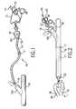
- FIG. 1is a side perspective view of a removeable string system containing a plurality of strings prior to its insertion into a body in accord with one embodiment of the present invention.
- FIG. 2is a side perspective view of the removeable string system containing a plurality of strings from FIG. 1 after it has been inserted into the body in accord with one embodiment of the present invention.
- FIG. 3is a side perspective view of the removeable string system containing a plurality of strings from FIG. 1 after it has been inserted into the body and after the strings have been connected to the filaments of the ligation tip in accord with one embodiment of the present invention.
- FIG. 4is a side perspective view of one of the strings, from the plurality of strings, being pulled in order to deploy a ligation band in accord with one embodiment of the present invention.
- FIG. 5is a side perspective view of a medical apparatus in accord with one embodiment of the present invention.
- FIG. 6is a side perspective view of the medical apparatus from FIG. 5 being used by a practitioner in accord with one embodiment of the present invention.
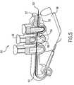
- FIG. 7is a side perspective view of a medical apparatus in accord with one embodiment of the present invention.
- FIGS. 1-4illustrate the components, assembly, and use of a medical device or apparatus that may be used to deploy ligation bands or other medical appliances within the body of a patient in accord with one embodiment of the present invention.
- the medical device depicted in these figuresmay be used independently or in conjunction with an endoscope or other device to perform endoscopic tubal ligations as well as numerous other procedures.
- FIG. 1is a side perspective view of some of the components of the medical device that is depicted in FIGS. 1-4 (wherein like elements have been numbered throughout with like numerals).
- FIG. 1illustrates the removable cable system 10 prior to its insertion into the y-extension extension 103 of tube or body 19 which may be an endoscope or any other device capable of creating an operating channel to a target site in the patient in accord with one embodiment of the present invention.
- this removable cable system 10contains a plurality of filaments or strings 13 running through a flexible sheath 11 .
- the sheath 11which may be made from rubber, plastic or any other flexible and resilient material, may have a circular, hexagonal, octangular or other cross-sectional shape.
- the cross-sectional areabe sized such that the sheath 11 may readily encase each of the strings 13 traveling through it, that the strings may not be bound within the sheath 11 , that the strings 13 may be readily pulled back and forth through the sheath 11 and that the sheath 11 containing the strings 13 may be sized to fit within the body 19 and the y-extension extension 103 of the body 19 .
- the system 10 of FIG. 1may also include a sealing plug 18 having a bore 102 traveling through it wherein the bore 102 is sized to allow the sheath 11 to slide back and forth within it.
- This sealing plug 18may be made from the same material as the sheath 11 or it may be made from a separate material. It may also be manufactured in conjunction with the sheath 11 or it may be placed around the sheath 11 after the sheath 11 has been manufactured. Moreover it may be added to the sheath either before and after the strings have been placed within the sheath 11 .
- the external sealing plug 18may have a tang portion 101 , as illustrated in FIG. 1, that is sized to frictionally secure the sealing plug 18 to the y-extension 103 of the body 19 .
- the system 10may continue to be able to slide in and out of the body 19 due to the size of the bore 102 in relation to the sheath 11 .
- the tang portion 101may contain threads that may be used to secure the sealing plug 18 to the body 19 .
- other securement configurations and methodologiessuch as bendable clips and adhesives, may also be used to secure the sealing plug 18 to the y-extension 103 of the body 19 .
- the sheath 11may also have a stopper 17 positioned on its outside surface. This stopper 17 may be made in conjunction with the sheath 11 or may be added at a later time. This stopper 17 is preferably fixedly secured to the sheath 11 and sized to prevent the sheath 11 from being completely slid through the bore 102 of the sealing plug 18 .
- the strings 13which are located within the sheath 11 , may have pulls 15 attached to one of their ends. These pulls 15 may have unique identifiers or tags 14 attached to them which act, with the pulls 15 , as a means for affirmatively verifying that the specific medical appliance from a plurality of medical appliances, has been deployed. Alternatively, rather than using a pull and tag system the pulls 15 may, themselves, be colored or otherwise identified to allow them to be effectively distinguished from one another.
- the opposite end of the strings 13may terminate in a loop or catch 16 or may at least be in physical communication with the loop or catch 16 .
- This catch 16may be used, as shown in FIG. 3, to releasably connect the individual strings 13 of the system 10 to hooks 20 associated with individual ligating bands that surround the ligation tip 30 in FIG. 3 and may be deployed by pulling on the pulls 15 during a medical procedure.
- the removeable cable system 10may be inserted into the y-extension extension 103 of the body 19 until the tang 101 of the sealing plug 18 comes to rest within the end of the y-extension 103 .
- the sheath 11 and the strings 13are sized such that when the sealing plug 18 comes to rest against the y-extension 103 of the body 19 the catches 16 extend past the distal end 22 of the body 19 .
- the catches 16may be readily attached to hooks 20 of the ligation tip 30 shown in FIG. 3 .
- FIG. 3illustrates a side view of the medical device from FIGS. 1-4 after the individual filaments 33 of the ligation tip 30 have been coupled to the strings 13 of the cable system 10 .
- the end 32 of the ligation tip 30may be slid around or into the open end 22 of the body 19 .
- the cable system 10may be pulled, as indicated by arrow 34 , to remove any slack in the lines created by the insertion and coupling process.
- the stopper 17may act to limit the distance that the cable system 10 may be pulled through the sealing plug 18 , and, thereby, prevent the premature deployment of all of the ligating bands from the tip 30 as would occur if the removable cable system 10 was pulled too far back up through the sealing plug 18 .
- the ligation tip 30which is fully evident in FIG. 4, may contain a plurality of ligation bands 31 that may be located around its outside surface. These ligation bands 31 may be individually coupled to the individual filaments 33 which are in turn individually coupled to the strings 13 . Thus, in use, as depicted in FIG. 4, by pulling on one of the pulls 15 as indicated by arrow 42 a specific ligation band 31 may be deployed from the ligation tip 30 as indicated by arrow 41 . Because each pull 15 has a unique marking to associate it with a specific deployable medical appliance, when an operator pulls a specifically marked pull, the operator will know which medical appliance, in this case a ligation band, is being deployed at that time. Thus, through this system, a practitioner may more accurately control the deployment of ligation bands from the distal end of a ligation unit as he can positively determine, from the proximal end of the device, which ligation band is being deployed
- FIG. 5is a side perspective view of an alternative embodiment of the present invention.
- a means 50 for affirmatively verifying the deployment of a medical appliance from a plurality of medical appliancescan be seen.
- Means 50may be attached to an endoscope as illustrated in FIG. 6 .
- Means 50may contain a plunger 52 , a body 56 , a string 53 , and a variable length string passageway 51 and may be used to deploy ligation bands or other medical appliances located at the distal end of an endoscope.
- Means 50accomplishes this task by shortening or otherwise pulling on a string contained within the passageway 51 that is coupled to a plurality of deployable medical appliances at the distal end of the endoscope.
- This stringis pulled or shortened by a specific predetermined distance by depressing one of the plungers 52 of the means 50 .
- the string 53 resident in the passageway 51 and coupled to anchoring point 57will have its effective length shortened by the distance that it must now travel around the depressed plunger 52 .
- the plunger 52by depressing the plunger 52 , the string will be shortened and a ligation band or other device coupled to the string may be deployed by the medical device.
- a specific method of using the means 50 from FIG. 5may include coupling the body 56 to an endoscope and then threading a string 53 through the string passageway 51 and anchoring point 57 .
- the distal end of the string 53may then be threaded around each deployable medical appliance in sequential order.
- the plunger 52may be depressed, in order to draw the string 53 into the valley 58 associated with the plunger 53 thus altering the string's pathway and shortening its effective length. Consequently, when a plunger 52 is depressed, a medical appliance coupled to the string's distal end may be deployed from the distal end of the medical device.
- a second plungermay be depressed while the first plunger is also depressed.
- the effective length of the stringwill be twice shortened and the second medical appliance may be deployed.
- a third appliancemay also be deployed by depressing the third plunger 52 while the first two are also depressed.
- the plungers in this embodimentmay be depressed in any order to deploy the first, second, and the third medical appliances since the string is not bound underneath the depressed plungers but, is rather, able to slide back and forth underneath the depressed plunger.
- the operatorcan readily detect the number of medical appliances that have been deployed and that, as can be seen in FIG. 6, the user may use a single hand to hold the endoscope and to deploy the medical appliances.
- the plungersmay be retained by some locking mechanism after the plunger has been depressed into the valleys 58 so that it is not necessary to hold down the plungers in order to deploy several bands.
- the plungersmay be biased in an open position to reduce the likelihood that the plunger will be errantly depressed by a practitioner during a procedure.
- Means 70may be placed at the distal end of an endoscope and may be used to pull a string a predetermined distance in order to deploy a ligation band in communication with the string from a ligation tip at the distal end of the endoscope.
- Means 70may include a shaft 76 , an opening 72 , and a slidable handle 71 coupled to the shaft 76 and adapted to be slid over the shaft 76 .
- the handle 71may also contain several slots 78 that may be sized to secure a looped end 75 of a string 701 that may be attached to a plurality of ligation bands at the distal end of the endoscope or other device. Consequently, as the handle 71 is incrementally advanced down the shaft 76 the string 701 may be pulled by that same incremental distance as the handle 71 is slid.
- a pulley systemmay be employed that adjusts or modifies the distance that handle 71 needs to be pulled before each ligation band is deployed.
- This pulley system or mechanical advantage systemmay increase the distance that the handle needs to be pulled or conversely decrease the distance that the handle needs to be pulled.
- FIG. 7Also evident in FIG. 7 are a plurality of stops 73 , 74 , and 77 that protrude from the shaft 76 and may be sized to arrest the travel of the handle 71 as it slides down the body 76 .
- stopsmay be integrally formed with the shaft 76 and may be compressible or incompressible.
- the compressible stops 73 and 77 in this embodimentmay be designed so that they may be depressed to allow the handle 71 to be slid over them and down the shaft from position to position as indicated by arrows 702 in FIG. 7 .
- stop 74which is fixed and incompressible in this embodiment, may act to prevent the handle 71 from sliding further down the body 76 , thus acting as a block at the end of the handle 71 .
- stopsmay also be used to arrest the travel of the handle 71 in the direction opposite to the arrows 702 .
- stop 79which is shown preventing the handle 71 from sliding closer to opening 703 and obstructing the string 701 that protrudes from it.
- the shaft or body of the devicemay be made from rigid plastic, surgical grade metals, and other suitable materials.
Landscapes
- Health & Medical Sciences (AREA)
- Surgery (AREA)
- Life Sciences & Earth Sciences (AREA)
- Heart & Thoracic Surgery (AREA)
- Nuclear Medicine, Radiotherapy & Molecular Imaging (AREA)
- Engineering & Computer Science (AREA)
- Biomedical Technology (AREA)
- Medical Informatics (AREA)
- Molecular Biology (AREA)
- Animal Behavior & Ethology (AREA)
- General Health & Medical Sciences (AREA)
- Public Health (AREA)
- Veterinary Medicine (AREA)
- Vascular Medicine (AREA)
- Reproductive Health (AREA)
- Surgical Instruments (AREA)
Abstract
Description
Claims (16)
Priority Applications (5)
| Application Number | Priority Date | Filing Date | Title |
|---|---|---|---|
| US09/902,636US6632228B2 (en) | 2000-08-23 | 2001-07-12 | System, method, and apparatus for accurately deploying particular medical appliances at a target site |
| US10/618,634US7060076B2 (en) | 2000-08-23 | 2003-07-15 | System, method, and apparatus for accurately deploying particular medical appliances at a target site |
| US11/368,539US7625385B2 (en) | 2000-08-23 | 2006-03-07 | Apparatus for accurately deploying particular medical appliances at a target site |
| US12/545,444US8043306B2 (en) | 2000-08-23 | 2009-08-21 | Methods for accurately deploying particular medical appliances at a target site |
| US13/238,833US8747422B2 (en) | 2000-08-23 | 2011-09-21 | Methods for accurately deploying particular medical appliances at a target site |
Applications Claiming Priority (2)
| Application Number | Priority Date | Filing Date | Title |
|---|---|---|---|
| US22690100P | 2000-08-23 | 2000-08-23 | |
| US09/902,636US6632228B2 (en) | 2000-08-23 | 2001-07-12 | System, method, and apparatus for accurately deploying particular medical appliances at a target site |
Related Child Applications (1)
| Application Number | Title | Priority Date | Filing Date |
|---|---|---|---|
| US10/618,634ContinuationUS7060076B2 (en) | 2000-08-23 | 2003-07-15 | System, method, and apparatus for accurately deploying particular medical appliances at a target site |
Publications (2)
| Publication Number | Publication Date |
|---|---|
| US20020026199A1 US20020026199A1 (en) | 2002-02-28 |
| US6632228B2true US6632228B2 (en) | 2003-10-14 |
Family
ID=26920971
Family Applications (5)
| Application Number | Title | Priority Date | Filing Date |
|---|---|---|---|
| US09/902,636Expired - LifetimeUS6632228B2 (en) | 2000-08-23 | 2001-07-12 | System, method, and apparatus for accurately deploying particular medical appliances at a target site |
| US10/618,634Expired - Fee RelatedUS7060076B2 (en) | 2000-08-23 | 2003-07-15 | System, method, and apparatus for accurately deploying particular medical appliances at a target site |
| US11/368,539Expired - Fee RelatedUS7625385B2 (en) | 2000-08-23 | 2006-03-07 | Apparatus for accurately deploying particular medical appliances at a target site |
| US12/545,444Expired - Fee RelatedUS8043306B2 (en) | 2000-08-23 | 2009-08-21 | Methods for accurately deploying particular medical appliances at a target site |
| US13/238,833Expired - Fee RelatedUS8747422B2 (en) | 2000-08-23 | 2011-09-21 | Methods for accurately deploying particular medical appliances at a target site |
Family Applications After (4)
| Application Number | Title | Priority Date | Filing Date |
|---|---|---|---|
| US10/618,634Expired - Fee RelatedUS7060076B2 (en) | 2000-08-23 | 2003-07-15 | System, method, and apparatus for accurately deploying particular medical appliances at a target site |
| US11/368,539Expired - Fee RelatedUS7625385B2 (en) | 2000-08-23 | 2006-03-07 | Apparatus for accurately deploying particular medical appliances at a target site |
| US12/545,444Expired - Fee RelatedUS8043306B2 (en) | 2000-08-23 | 2009-08-21 | Methods for accurately deploying particular medical appliances at a target site |
| US13/238,833Expired - Fee RelatedUS8747422B2 (en) | 2000-08-23 | 2011-09-21 | Methods for accurately deploying particular medical appliances at a target site |
Country Status (1)
| Country | Link |
|---|---|
| US (5) | US6632228B2 (en) |
Cited By (29)
| Publication number | Priority date | Publication date | Assignee | Title |
|---|---|---|---|---|
| US20050049564A1 (en)* | 2003-08-28 | 2005-03-03 | Fabian Carl E. | Attachment of electronic tags to surgical sponges and implements |
| US7367983B2 (en) | 2005-09-15 | 2008-05-06 | Dziadik Stephen P | Vessel harvesting apparatus |
| US20090043277A1 (en)* | 2007-08-10 | 2009-02-12 | Donald Lee Sturtevant | Treatment for patients after removal of saphenous vascular material |
| US9155554B2 (en) | 2011-10-27 | 2015-10-13 | Boston Scientific Scimed, Inc. | Tissue resection bander and related methods of use |
| US9351733B2 (en) | 2013-01-18 | 2016-05-31 | Covidien Lp | Surgical fastener applier |
| US9351728B2 (en) | 2013-06-28 | 2016-05-31 | Covidien Lp | Articulating apparatus for endoscopic procedures |
| US9358010B2 (en) | 2013-03-12 | 2016-06-07 | Covidien Lp | Flex cable and spring-loaded tube for tacking device |
| US9358004B2 (en) | 2013-06-28 | 2016-06-07 | Covidien Lp | Articulating apparatus for endoscopic procedures |
| US9364274B2 (en) | 2003-06-13 | 2016-06-14 | Covidien Lp | Multiple member interconnect for surgical instrument and absorbable screw fastener |
| US9526498B2 (en) | 2013-09-17 | 2016-12-27 | Covidien Lp | Surgical device with a trigger lockout mechanism device |
| US9636137B2 (en) | 2011-10-27 | 2017-05-02 | Boston Scientific Scimed, Inc. | Mucosal resection device and related methods of use |
| US9655621B2 (en) | 2013-03-15 | 2017-05-23 | Covidien Lp | Surgical instrument for dispensing tacks and solution |
| US9668730B2 (en) | 2013-06-28 | 2017-06-06 | Covidien Lp | Articulating apparatus for endoscopic procedures with timing system |
| US9867620B2 (en) | 2013-03-14 | 2018-01-16 | Covidien Lp | Articulation joint for apparatus for endoscopic procedures |
| US10085746B2 (en) | 2013-06-28 | 2018-10-02 | Covidien Lp | Surgical instrument including rotating end effector and rotation-limiting structure |
| US10098634B2 (en) | 2004-04-27 | 2018-10-16 | Covidien Lp | Absorbable fastener for hernia mesh fixation |
| US10335146B2 (en) | 2014-04-02 | 2019-07-02 | Coviden Lp | Surgical fastener applying apparatus, kits and methods for endoscopic procedures |
| US10617409B2 (en) | 2016-10-21 | 2020-04-14 | Covidien Lp | Surgical end effectors |
| US10653507B2 (en) | 2013-07-24 | 2020-05-19 | Covidien Lp | Expanding absorbable tack |
| US10743859B2 (en) | 2016-10-21 | 2020-08-18 | Covidien Lp | Surgical end effectors |
| US10888309B2 (en) | 2017-01-31 | 2021-01-12 | Covidien Lp | Surgical fastener devices with geometric tubes |
| US11090097B2 (en) | 2015-03-17 | 2021-08-17 | Covidien Lp | Connecting end effectors to surgical devices |
| US11116500B2 (en) | 2018-06-28 | 2021-09-14 | Covidien Lp | Surgical fastener applying device, kits and methods for endoscopic procedures |
| US11197675B2 (en) | 2019-12-19 | 2021-12-14 | Covidien Lp | Positioning guide for surgical instruments and surgical instrument systems |
| USD944984S1 (en) | 2019-12-19 | 2022-03-01 | Covidien Lp | Tubular positioning guide |
| USD944985S1 (en) | 2019-12-19 | 2022-03-01 | Covidien Lp | Positioning guide cuff |
| US11298126B2 (en) | 2018-05-02 | 2022-04-12 | Covidien Lp | Shipping wedge for end effector installation onto surgical devices |
| US11298123B2 (en) | 2016-10-21 | 2022-04-12 | Covidien Lp | Surgical end effectors |
| US11523817B2 (en) | 2019-06-27 | 2022-12-13 | Covidien Lp | Endoluminal pursestring device |
Families Citing this family (21)
| Publication number | Priority date | Publication date | Assignee | Title |
|---|---|---|---|---|
| US6632228B2 (en)* | 2000-08-23 | 2003-10-14 | Scimed Life System, Inc. | System, method, and apparatus for accurately deploying particular medical appliances at a target site |
| CA2722645A1 (en) | 2002-07-31 | 2004-02-19 | Power Medical Interventions, Llc | Orifice introducer device |
| US8821515B2 (en)* | 2006-10-16 | 2014-09-02 | Boston Scientific Scimed, Inc. | Ligating instrument |
| DE102007000151A1 (en)* | 2007-03-14 | 2008-09-18 | Ovesco Endoscopy Gmbh | Medical gripping device |
| US20080228164A1 (en)* | 2007-03-14 | 2008-09-18 | Nicoson Zachary R | Implant delivery system |
| US20100023025A1 (en)* | 2008-07-25 | 2010-01-28 | Zeiner Mark S | Reloadable laparoscopic fastener deploying device with disposable cartridge for use in a gastric volume reduction procedure |
| US20100023024A1 (en)* | 2008-07-25 | 2010-01-28 | Zeiner Mark S | Reloadable laparoscopic fastener deploying device with disposable cartridge for use in a gastric volume reduction procedure |
| US20100023026A1 (en)* | 2008-07-25 | 2010-01-28 | Zeiner Mark S | Reloadable laparoscopic fastener deploying device with disposable cartridge for use in a gastric volume reduction procedure |
| US20100023022A1 (en)* | 2008-07-25 | 2010-01-28 | Zeiner Mark S | Reloadable laparoscopic fastener deploying device with disposable cartridge use in a gastric volume reduction procedure |
| US20100160777A1 (en)* | 2008-12-22 | 2010-06-24 | Hardin Terry D | Reverse deployment device |
| WO2011041069A1 (en)* | 2009-09-30 | 2011-04-07 | Boston Scientific Scimed, Inc. | Ligating band dispenser device |
| WO2013130658A1 (en)* | 2012-02-27 | 2013-09-06 | Kamler Jan | Banding apparatus and method of use |
| US20140142618A1 (en)* | 2012-09-12 | 2014-05-22 | ProMed, Inc. | Systems and Methods for Improved Vessel Access Closure |
| WO2014042686A1 (en) | 2012-09-14 | 2014-03-20 | Kamler Jan | Ligator and method of use |
| US9101360B2 (en)* | 2013-08-21 | 2015-08-11 | Crh Medical Corporation | Elastic band ligation device with integrated obturator and method for treatment of hemorrhoids |
| US9622750B2 (en)* | 2013-08-21 | 2017-04-18 | Crh Medical Corporation | Elastic band ligation device with locking mechanism and method for treatment of hemorrhoids |
| US20150057680A1 (en) | 2013-08-21 | 2015-02-26 | Crh Medical Corporation | Elastic band ligation device with anti-pinch feature and method for treatment of hemorrhoids |
| US9308357B2 (en)* | 2013-10-16 | 2016-04-12 | Gary Lovell | Cyst extractor |
| US9962175B2 (en) | 2013-10-16 | 2018-05-08 | Gary Lovell | Methods of use of an anatomic structure extractor |
| US10603042B2 (en)* | 2016-02-10 | 2020-03-31 | Covidien Lp | Flexible circular stapler |
| US11166624B2 (en)* | 2020-02-21 | 2021-11-09 | Ambu A/S | Medical visualization system |
Citations (5)
| Publication number | Priority date | Publication date | Assignee | Title |
|---|---|---|---|---|
| US5398844A (en) | 1994-01-31 | 1995-03-21 | Boston Scientific Corporation | Multiple ligating band dispenser |
| US5766216A (en)* | 1996-05-30 | 1998-06-16 | Gangal; Hanamraddi T. | Band applicator for appendicular and meso-appendicular stumps |
| US5817033A (en) | 1994-04-11 | 1998-10-06 | Desantis; Stephen A. | Needle core biopsy device |
| US5857585A (en) | 1996-05-28 | 1999-01-12 | Act Medical, Inc. | Ligating band dispenser |
| US6280452B1 (en)* | 1998-06-22 | 2001-08-28 | Ensurg, Inc. | Balloon actuated ligating band dispenser |
Family Cites Families (6)
| Publication number | Priority date | Publication date | Assignee | Title |
|---|---|---|---|---|
| US4226239A (en)* | 1978-01-31 | 1980-10-07 | Kli, Inc. | Surgical ligating instrument and method |
| US5197649A (en)* | 1991-10-29 | 1993-03-30 | The Trustees Of Columbia University In The City Of New York | Gastrointestinal endoscoptic stapler |
| US5476662A (en)* | 1992-11-13 | 1995-12-19 | Isp Investments Inc. | Pesticide or herbicide polymer complexes for forming aqueous dispersions |
| US6685713B1 (en)* | 1993-02-22 | 2004-02-03 | Dabegran Technologies, Inc. | Endoscopic ligating apparatus |
| US5626585A (en)* | 1994-09-16 | 1997-05-06 | United States Surgical Corporation | Ligating clip advance |
| US6632228B2 (en)* | 2000-08-23 | 2003-10-14 | Scimed Life System, Inc. | System, method, and apparatus for accurately deploying particular medical appliances at a target site |
- 2001
- 2001-07-12USUS09/902,636patent/US6632228B2/ennot_activeExpired - Lifetime
- 2003
- 2003-07-15USUS10/618,634patent/US7060076B2/ennot_activeExpired - Fee Related
- 2006
- 2006-03-07USUS11/368,539patent/US7625385B2/ennot_activeExpired - Fee Related
- 2009
- 2009-08-21USUS12/545,444patent/US8043306B2/ennot_activeExpired - Fee Related
- 2011
- 2011-09-21USUS13/238,833patent/US8747422B2/ennot_activeExpired - Fee Related
Patent Citations (5)
| Publication number | Priority date | Publication date | Assignee | Title |
|---|---|---|---|---|
| US5398844A (en) | 1994-01-31 | 1995-03-21 | Boston Scientific Corporation | Multiple ligating band dispenser |
| US5817033A (en) | 1994-04-11 | 1998-10-06 | Desantis; Stephen A. | Needle core biopsy device |
| US5857585A (en) | 1996-05-28 | 1999-01-12 | Act Medical, Inc. | Ligating band dispenser |
| US5766216A (en)* | 1996-05-30 | 1998-06-16 | Gangal; Hanamraddi T. | Band applicator for appendicular and meso-appendicular stumps |
| US6280452B1 (en)* | 1998-06-22 | 2001-08-28 | Ensurg, Inc. | Balloon actuated ligating band dispenser |
Cited By (48)
| Publication number | Priority date | Publication date | Assignee | Title |
|---|---|---|---|---|
| US9662106B2 (en) | 2003-06-13 | 2017-05-30 | Covidien Lp | Surgical fastener with predetermined resorption rate |
| US9364274B2 (en) | 2003-06-13 | 2016-06-14 | Covidien Lp | Multiple member interconnect for surgical instrument and absorbable screw fastener |
| US7399899B2 (en)* | 2003-08-28 | 2008-07-15 | Fabian Carl E | Attachment of electronic tags to surgical sponges and implements |
| US20050049564A1 (en)* | 2003-08-28 | 2005-03-03 | Fabian Carl E. | Attachment of electronic tags to surgical sponges and implements |
| US10098634B2 (en) | 2004-04-27 | 2018-10-16 | Covidien Lp | Absorbable fastener for hernia mesh fixation |
| US7367983B2 (en) | 2005-09-15 | 2008-05-06 | Dziadik Stephen P | Vessel harvesting apparatus |
| US20090043277A1 (en)* | 2007-08-10 | 2009-02-12 | Donald Lee Sturtevant | Treatment for patients after removal of saphenous vascular material |
| US8623046B2 (en) | 2007-08-10 | 2014-01-07 | Donald Lee Sturtevant | Treatment for patients after removal of saphenous vascular material |
| US10285726B2 (en) | 2011-10-27 | 2019-05-14 | Boston Sientific Scimed, Inc. | Mucosal resection device and related methods of use |
| US9872600B2 (en) | 2011-10-27 | 2018-01-23 | Boston Scientific Scimed, Inc. | Tissue resection bander and related methods of use |
| US9636137B2 (en) | 2011-10-27 | 2017-05-02 | Boston Scientific Scimed, Inc. | Mucosal resection device and related methods of use |
| US9155554B2 (en) | 2011-10-27 | 2015-10-13 | Boston Scientific Scimed, Inc. | Tissue resection bander and related methods of use |
| US9629649B2 (en) | 2011-10-27 | 2017-04-25 | Boston Scientific Scimed, Inc. | Tissue resection bander and related methods of use |
| US10226248B2 (en) | 2013-01-18 | 2019-03-12 | Covidien Lp | Surgical fastener applier |
| US9351733B2 (en) | 2013-01-18 | 2016-05-31 | Covidien Lp | Surgical fastener applier |
| US9358010B2 (en) | 2013-03-12 | 2016-06-07 | Covidien Lp | Flex cable and spring-loaded tube for tacking device |
| US10105135B2 (en) | 2013-03-12 | 2018-10-23 | Covidien Lp | Flex cable and spring-loaded tube for tacking device |
| US10869671B2 (en) | 2013-03-14 | 2020-12-22 | Covidien Lp | Articulation joint for apparatus for endoscopic procedures |
| US9867620B2 (en) | 2013-03-14 | 2018-01-16 | Covidien Lp | Articulation joint for apparatus for endoscopic procedures |
| US10806455B2 (en) | 2013-03-15 | 2020-10-20 | Covidien Lp | Surgical instrument for dispensing tacks and solution |
| US9655621B2 (en) | 2013-03-15 | 2017-05-23 | Covidien Lp | Surgical instrument for dispensing tacks and solution |
| US9351728B2 (en) | 2013-06-28 | 2016-05-31 | Covidien Lp | Articulating apparatus for endoscopic procedures |
| US10786250B2 (en) | 2013-06-28 | 2020-09-29 | Covidien Lp | Surgical instrument including rotating end effector and rotation-limiting structure |
| US10188387B2 (en) | 2013-06-28 | 2019-01-29 | Covidien Lp | Articulating apparatus for endoscopic procedures |
| US11266401B2 (en) | 2013-06-28 | 2022-03-08 | Covidien Lp | Articulating apparatus for endoscopic procedures with timing system |
| US9358004B2 (en) | 2013-06-28 | 2016-06-07 | Covidien Lp | Articulating apparatus for endoscopic procedures |
| US9668730B2 (en) | 2013-06-28 | 2017-06-06 | Covidien Lp | Articulating apparatus for endoscopic procedures with timing system |
| US10588627B2 (en) | 2013-06-28 | 2020-03-17 | Covidien Lp | Articulating apparatus for endoscopic procedures with timing system |
| US10085746B2 (en) | 2013-06-28 | 2018-10-02 | Covidien Lp | Surgical instrument including rotating end effector and rotation-limiting structure |
| US9783329B2 (en) | 2013-06-28 | 2017-10-10 | Covidien Lp | Articulating apparatus with shipping wedge |
| US10653507B2 (en) | 2013-07-24 | 2020-05-19 | Covidien Lp | Expanding absorbable tack |
| US9526498B2 (en) | 2013-09-17 | 2016-12-27 | Covidien Lp | Surgical device with a trigger lockout mechanism device |
| US10335146B2 (en) | 2014-04-02 | 2019-07-02 | Coviden Lp | Surgical fastener applying apparatus, kits and methods for endoscopic procedures |
| US11871976B2 (en) | 2015-03-17 | 2024-01-16 | Covidien Lp | Connecting end effectors to surgical devices |
| US11090097B2 (en) | 2015-03-17 | 2021-08-17 | Covidien Lp | Connecting end effectors to surgical devices |
| US10743859B2 (en) | 2016-10-21 | 2020-08-18 | Covidien Lp | Surgical end effectors |
| US11298123B2 (en) | 2016-10-21 | 2022-04-12 | Covidien Lp | Surgical end effectors |
| US11382614B2 (en) | 2016-10-21 | 2022-07-12 | Covidien Lp | Surgical end effectors |
| US11596396B2 (en) | 2016-10-21 | 2023-03-07 | Covidien Lp | Surgical end effectors |
| US10617409B2 (en) | 2016-10-21 | 2020-04-14 | Covidien Lp | Surgical end effectors |
| US10888309B2 (en) | 2017-01-31 | 2021-01-12 | Covidien Lp | Surgical fastener devices with geometric tubes |
| US11298126B2 (en) | 2018-05-02 | 2022-04-12 | Covidien Lp | Shipping wedge for end effector installation onto surgical devices |
| US11779328B2 (en) | 2018-05-02 | 2023-10-10 | Covidien Lp | Shipping wedge for end effector installation onto surgical devices |
| US11116500B2 (en) | 2018-06-28 | 2021-09-14 | Covidien Lp | Surgical fastener applying device, kits and methods for endoscopic procedures |
| US11523817B2 (en) | 2019-06-27 | 2022-12-13 | Covidien Lp | Endoluminal pursestring device |
| US11197675B2 (en) | 2019-12-19 | 2021-12-14 | Covidien Lp | Positioning guide for surgical instruments and surgical instrument systems |
| USD944984S1 (en) | 2019-12-19 | 2022-03-01 | Covidien Lp | Tubular positioning guide |
| USD944985S1 (en) | 2019-12-19 | 2022-03-01 | Covidien Lp | Positioning guide cuff |
Also Published As
| Publication number | Publication date |
|---|---|
| US8043306B2 (en) | 2011-10-25 |
| US7625385B2 (en) | 2009-12-01 |
| US7060076B2 (en) | 2006-06-13 |
| US20020026199A1 (en) | 2002-02-28 |
| US20040097969A1 (en) | 2004-05-20 |
| US20120010632A1 (en) | 2012-01-12 |
| US20090312771A1 (en) | 2009-12-17 |
| US20060161181A1 (en) | 2006-07-20 |
| US8747422B2 (en) | 2014-06-10 |
Similar Documents
| Publication | Publication Date | Title |
|---|---|---|
| US6632228B2 (en) | System, method, and apparatus for accurately deploying particular medical appliances at a target site | |
| EP1880681B1 (en) | Combination knotting element and suture anchor applicator | |
| AU2007202249B2 (en) | Combination knotting element and suture anchor applicator | |
| US8888795B2 (en) | Suture passer | |
| ES2796738T3 (en) | System for transection through thread of a ligament | |
| EP2967562B1 (en) | Surgical tacker with quantity indicator | |
| US20230027249A1 (en) | Over the scope clip with repositional capability | |
| KR20230125054A (en) | Repositioning Clips with Extensions | |
| EP2755566B1 (en) | Endoscopic hemostasis closure device and delivery system | |
| US20230055904A1 (en) | Interface mechanism for repositioning and deployment of over the scope clip | |
| US20230053352A1 (en) | Endoscopic clip with positive lock | |
| US20230036540A1 (en) | Repositionable over the scope clip |
Legal Events
| Date | Code | Title | Description |
|---|---|---|---|
| AS | Assignment | Owner name:ACT MEDICAL, INC., MASSACHUSETTS Free format text:ASSIGNMENT OF ASSIGNORS INTEREST;ASSIGNORS:FORTIER, RICHARD;MCCABE, MARGARET;BOWEN, MARK;REEL/FRAME:011992/0005;SIGNING DATES FROM 20010104 TO 20010123 | |
| AS | Assignment | Owner name:SCIMED LIFE SYSTEMS, INC., MINNESOTA Free format text:ASSIGNMENT OF ASSIGNORS INTEREST;ASSIGNOR:ACT MEDICAL, INC.;REEL/FRAME:011991/0993 Effective date:20010104 | |
| STCF | Information on status: patent grant | Free format text:PATENTED CASE | |
| FEPP | Fee payment procedure | Free format text:PAYOR NUMBER ASSIGNED (ORIGINAL EVENT CODE: ASPN); ENTITY STATUS OF PATENT OWNER: LARGE ENTITY | |
| AS | Assignment | Owner name:BOSTON SCIENTIFIC SCIMED, INC., MINNESOTA Free format text:CHANGE OF NAME;ASSIGNOR:SCIMED LIFE SYSTEMS, INC.;REEL/FRAME:018505/0868 Effective date:20050101 Owner name:BOSTON SCIENTIFIC SCIMED, INC.,MINNESOTA Free format text:CHANGE OF NAME;ASSIGNOR:SCIMED LIFE SYSTEMS, INC.;REEL/FRAME:018505/0868 Effective date:20050101 | |
| FPAY | Fee payment | Year of fee payment:4 | |
| FPAY | Fee payment | Year of fee payment:8 | |
| FPAY | Fee payment | Year of fee payment:12 |