US6632089B2 - Orthodontic treatment planning with user-specified simulation of tooth movement - Google Patents
Orthodontic treatment planning with user-specified simulation of tooth movementDownload PDFInfo
- Publication number
- US6632089B2 US6632089B2US09/834,412US83441201AUS6632089B2US 6632089 B2US6632089 B2US 6632089B2US 83441201 AUS83441201 AUS 83441201AUS 6632089 B2US6632089 B2US 6632089B2
- Authority
- US
- United States
- Prior art keywords
- teeth
- virtual
- patient
- tooth
- brackets
- Prior art date
- Legal status (The legal status is an assumption and is not a legal conclusion. Google has not performed a legal analysis and makes no representation as to the accuracy of the status listed.)
- Expired - Lifetime, expires
Links
- 238000011282treatmentMethods0.000titleclaimsabstractdescription152
- 230000033001locomotionEffects0.000titleclaimsabstractdescription52
- 238000004088simulationMethods0.000titleabstractdescription19
- 230000036346tooth eruptionEffects0.000claimsabstractdescription83
- 210000004513dentitionAnatomy0.000claimsabstractdescription82
- 238000000034methodMethods0.000claimsabstractdescription78
- 238000012545processingMethods0.000claimsdescription28
- 210000003484anatomyAnatomy0.000claimsdescription18
- 230000008859changeEffects0.000claimsdescription18
- 238000004519manufacturing processMethods0.000claimsdescription16
- 238000005259measurementMethods0.000claimsdescription11
- 238000001727in vivoMethods0.000claimsdescription6
- 206010061274MalocclusionDiseases0.000abstractdescription39
- 230000002452interceptive effectEffects0.000abstractdescription14
- 238000012986modificationMethods0.000abstractdescription7
- 230000004048modificationEffects0.000abstractdescription7
- 238000012552reviewMethods0.000abstractdescription4
- 238000012937correctionMethods0.000description32
- 238000013461designMethods0.000description27
- 238000003384imaging methodMethods0.000description20
- 230000008569processEffects0.000description17
- 210000001847jawAnatomy0.000description12
- 238000000605extractionMethods0.000description11
- 230000006870functionEffects0.000description9
- 238000012544monitoring processMethods0.000description9
- 238000005094computer simulationMethods0.000description8
- 238000005452bendingMethods0.000description7
- 238000004891communicationMethods0.000description7
- 230000001186cumulative effectEffects0.000description7
- 238000003745diagnosisMethods0.000description7
- 210000004283incisorAnatomy0.000description7
- 238000000926separation methodMethods0.000description7
- 238000012546transferMethods0.000description7
- 238000004422calculation algorithmMethods0.000description6
- 241001074085Scophthalmus aquosusSpecies0.000description5
- 238000013459approachMethods0.000description5
- 239000011888foilSubstances0.000description5
- 238000007726management methodMethods0.000description5
- 239000011505plasterSubstances0.000description5
- 238000013519translationMethods0.000description5
- 239000000853adhesiveSubstances0.000description4
- 230000001070adhesive effectEffects0.000description4
- 230000008901benefitEffects0.000description4
- 210000000988bone and boneAnatomy0.000description4
- 210000003464cuspidAnatomy0.000description4
- 238000010586diagramMethods0.000description4
- 238000005286illuminationMethods0.000description4
- 210000004373mandibleAnatomy0.000description4
- 239000000463materialSubstances0.000description4
- 230000003213activating effectEffects0.000description3
- 238000004364calculation methodMethods0.000description3
- 238000002591computed tomographyMethods0.000description3
- 238000005516engineering processMethods0.000description3
- 230000003993interactionEffects0.000description3
- 239000003550markerSubstances0.000description3
- 210000002050maxillaAnatomy0.000description3
- 238000003801millingMethods0.000description3
- 210000000214mouthAnatomy0.000description3
- 238000002604ultrasonographyMethods0.000description3
- 239000013598vectorSubstances0.000description3
- 241000282465CanisSpecies0.000description2
- GWEVSGVZZGPLCZ-UHFFFAOYSA-NTitan oxideChemical compoundO=[Ti]=OGWEVSGVZZGPLCZ-UHFFFAOYSA-N0.000description2
- 230000001055chewing effectEffects0.000description2
- 238000011960computer-aided designMethods0.000description2
- 239000004020conductorSubstances0.000description2
- 238000001514detection methodMethods0.000description2
- 238000011161developmentMethods0.000description2
- 230000018109developmental processEffects0.000description2
- 238000006073displacement reactionMethods0.000description2
- 239000003814drugSubstances0.000description2
- 230000008676importEffects0.000description2
- 238000007373indentationMethods0.000description2
- 230000003287optical effectEffects0.000description2
- 238000007639printingMethods0.000description2
- 230000009467reductionEffects0.000description2
- 230000009466transformationEffects0.000description2
- 230000000007visual effectEffects0.000description2
- 241000282412HomoSpecies0.000description1
- 230000004913activationEffects0.000description1
- 230000006978adaptationEffects0.000description1
- 238000004458analytical methodMethods0.000description1
- 238000000149argon plasma sinteringMethods0.000description1
- 230000005540biological transmissionEffects0.000description1
- 230000015556catabolic processEffects0.000description1
- 239000011248coating agentSubstances0.000description1
- 238000000576coating methodMethods0.000description1
- 238000010276constructionMethods0.000description1
- 238000001816coolingMethods0.000description1
- 238000005520cutting processMethods0.000description1
- 238000013500data storageMethods0.000description1
- 210000004489deciduous teethAnatomy0.000description1
- 230000001419dependent effectEffects0.000description1
- 238000004141dimensional analysisMethods0.000description1
- 238000009826distributionMethods0.000description1
- 230000000694effectsEffects0.000description1
- 230000001815facial effectEffects0.000description1
- 238000009499grossingMethods0.000description1
- 210000003128headAnatomy0.000description1
- 238000011221initial treatmentMethods0.000description1
- 230000000977initiatory effectEffects0.000description1
- 238000007689inspectionMethods0.000description1
- 230000013011matingEffects0.000description1
- 230000007246mechanismEffects0.000description1
- 238000004091panningMethods0.000description1
- 230000003239periodontal effectEffects0.000description1
- 239000004033plasticSubstances0.000description1
- 239000002985plastic filmSubstances0.000description1
- 238000003825pressingMethods0.000description1
- 238000011002quantificationMethods0.000description1
- 238000007493shaping processMethods0.000description1
- 210000004872soft tissueAnatomy0.000description1
- 239000007787solidSubstances0.000description1
- 239000000126substanceSubstances0.000description1
- 238000010408sweepingMethods0.000description1
- 230000001360synchronised effectEffects0.000description1
- 230000001225therapeutic effectEffects0.000description1
- 229920001169thermoplasticPolymers0.000description1
- 239000004416thermosoftening plasticSubstances0.000description1
- 210000001519tissueAnatomy0.000description1
- 239000004408titanium dioxideSubstances0.000description1
- 230000036339tooth positioningEffects0.000description1
- 238000011277treatment modalityMethods0.000description1
- 238000009966trimmingMethods0.000description1
Images


Classifications
- A—HUMAN NECESSITIES
- A61—MEDICAL OR VETERINARY SCIENCE; HYGIENE
- A61C—DENTISTRY; APPARATUS OR METHODS FOR ORAL OR DENTAL HYGIENE
- A61C7/00—Orthodontics, i.e. obtaining or maintaining the desired position of teeth, e.g. by straightening, evening, regulating, separating, or by correcting malocclusions
- A61C7/12—Brackets; Arch wires; Combinations thereof; Accessories therefor
- A61C7/14—Brackets; Fixing brackets to teeth
- A61C7/146—Positioning or placement of brackets; Tools therefor
- A—HUMAN NECESSITIES
- A61—MEDICAL OR VETERINARY SCIENCE; HYGIENE
- A61C—DENTISTRY; APPARATUS OR METHODS FOR ORAL OR DENTAL HYGIENE
- A61C9/00—Impression cups, i.e. impression trays; Impression methods
- A61C9/004—Means or methods for taking digitized impressions
- A61C9/0046—Data acquisition means or methods
- A61C9/0053—Optical means or methods, e.g. scanning the teeth by a laser or light beam
- A61C9/006—Optical means or methods, e.g. scanning the teeth by a laser or light beam projecting one or more stripes or patterns on the teeth
- A—HUMAN NECESSITIES
- A61—MEDICAL OR VETERINARY SCIENCE; HYGIENE
- A61C—DENTISTRY; APPARATUS OR METHODS FOR ORAL OR DENTAL HYGIENE
- A61C7/00—Orthodontics, i.e. obtaining or maintaining the desired position of teeth, e.g. by straightening, evening, regulating, separating, or by correcting malocclusions
- A61C7/002—Orthodontic computer assisted systems
- A—HUMAN NECESSITIES
- A61—MEDICAL OR VETERINARY SCIENCE; HYGIENE
- A61F—FILTERS IMPLANTABLE INTO BLOOD VESSELS; PROSTHESES; DEVICES PROVIDING PATENCY TO, OR PREVENTING COLLAPSING OF, TUBULAR STRUCTURES OF THE BODY, e.g. STENTS; ORTHOPAEDIC, NURSING OR CONTRACEPTIVE DEVICES; FOMENTATION; TREATMENT OR PROTECTION OF EYES OR EARS; BANDAGES, DRESSINGS OR ABSORBENT PADS; FIRST-AID KITS
- A61F2/00—Filters implantable into blood vessels; Prostheses, i.e. artificial substitutes or replacements for parts of the body; Appliances for connecting them with the body; Devices providing patency to, or preventing collapsing of, tubular structures of the body, e.g. stents
- A61F2/02—Prostheses implantable into the body
- A61F2/30—Joints
- A61F2/3094—Designing or manufacturing processes
- A61F2/30942—Designing or manufacturing processes for designing or making customized prostheses, e.g. using templates, CT or NMR scans, finite-element analysis or CAD-CAM techniques
- A61F2002/30953—Designing or manufacturing processes for designing or making customized prostheses, e.g. using templates, CT or NMR scans, finite-element analysis or CAD-CAM techniques using a remote computer network, e.g. Internet
- B—PERFORMING OPERATIONS; TRANSPORTING
- B33—ADDITIVE MANUFACTURING TECHNOLOGY
- B33Y—ADDITIVE MANUFACTURING, i.e. MANUFACTURING OF THREE-DIMENSIONAL [3-D] OBJECTS BY ADDITIVE DEPOSITION, ADDITIVE AGGLOMERATION OR ADDITIVE LAYERING, e.g. BY 3-D PRINTING, STEREOLITHOGRAPHY OR SELECTIVE LASER SINTERING
- B33Y80/00—Products made by additive manufacturing
Definitions
- This inventionrelates generally to the field of computer-interactive methods for diagnosis, care and treatment planning, therapeutics and treatment monitoring in the medical arena, including orthodontics.
- the inventionalso relates to real-time computer-interactive communication between a medical practitioner and his or her patient regarding diagnosis, care and treatment planning, therapeutics and treatment monitoring, and between a medical practitioner and a remotely located entities regarding these matters.
- the inventionrelates to a computerized and interactive method of planning orthodontic treatment for a patient suffering from a malocclusion.
- the patient's teethare represented in a computer as three-dimensional virtual objects.
- the orthodontistmay simulate various types of tooth movement and appliances, analyze the simulation, and thereby explore possible treatment options and appliance designs, prior to initiating treatment.
- a patient suffering from a malocclusionis typically treated by bonding brackets to the surface of the patient's teeth.
- the bracketshave slots for receiving an archwire.
- the bracket-archwire interactiongoverns forces applied to the teeth and defines the desired direction of tooth movement.
- the bends in the wireare made manually by the orthodontist.
- the movement of the teethis monitored. Corrections to the bracket position and/or wire shape are made manually by the orthodontist.
- the key to efficiency in treatment and maximum quality in resultsis a realistic simulation of the treatment process.
- Today's orthodontistshave the possibility of taking plaster models of the upper and lower jaw, cutting the model into single tooth models and sticking these tooth models into a wax bed, lining them up in the desired position, the so-called set-up. This approach allows for reaching a perfect occlusion without any guessing.
- the next stepis to bond a bracket at every tooth model. This would tell the orthodontist the geometry of the wire to run through the bracket slots to receive exactly this result.
- the next stepinvolves the transfer of the bracket position to the original malocclusion model.
- bracketsTo make sure that the brackets will be bonded at exactly this position at the real patient's teeth, small templates for every tooth would have to be fabricated that fit over the bracket and a relevant part of the tooth and allow for reliable placement of the bracket on the patient's teeth.
- another optionwould be to place each single bracket onto a model of the malocclusion and then fabricate one single transfer tray per jaw that covers all brackets and relevant portions of every tooth. Using such a transfer tray guarantees a very quick and yet precise bonding using indirect bonding.
- U.S. Pat. No. 5,431,562 to Andreiko et al.describes a computerized, appliance-driven approach to orthodontics.
- first certain shape information of teethis acquired.
- a uniplanar target arcformis calculated from the shape information.
- the shape of customized bracket slots, the bracket base, and the shape of the orthodontic archwire,are calculated in accordance with a mathematically-derived target archform.
- the goal of the Andreiko et al. methodis to give moe predictablity, standardization, and certainty to orthodontics by replacing the human element in orthodontic appliance design with a deterministic, mathematical computation of a target archform and appliance design.
- the '562 patentteaches away from an interactive, computer-based system in which the orthodontist remains fully involved in patient diagnosis, appliance design, and treatment planning and monitoring.
- the arthas lacked an effective, computer-based interactive orthodontic treatment planning system that provides the necessary tools to allow the orthodontist to quickly and efficiently design a treatment plan for a patient.
- the arthas also lacked a treatment planning system in which the orthodontist-derived parameters for the treatment can be translated into a design of an orthodontic appliance in real time, while the patient is in the chair.
- Real-time appliance design as described hereinalso allows for real-time communication of the treatment plan or appliance design to occur with the patient, or transmitted over a communications link and shared with a colleague or remote appliance manufacturing facility.
- the treatment planningcan be performed remotely and a digital treatment plan sent to the orthodontist for review, interactive modification, or approval.
- apparatus for treatment planning for an orthodontic patientcan be considered an interactive, computer-based computer aided design and computer aided manufacturing (CAD/CAM) system for orthodontics.
- CAD/CAMcomputer aided design and computer aided manufacturing
- the apparatusis highly interactive, in that it provides the orthodontist with the opportunity to both observe and analyze the current stage of the patient's condition and develop and specify a target or desired stage. A shortest direct path of tooth movement to the target stage can also be determined. Further, the apparatus provides for simulation of tooth movement between current and target stages.
- the apparatuscomprises a workstation having a processing unit and a display, and a memory storing a virtual, complete three-dimensional model representing the dentition of a patient.
- the virtual three-dimensional modelcan be obtained from one of several possible sources; in the preferred embodiment it is arrived at from a scanning of the dentition.
- the apparatusfurther includes software executable by the processing unit that accesses the model and displays the model on the display of the workstation.
- the softwarefurther includes navigation tools, e.g., typed commands, icons and/or graphical devices superimposed on the displayed model, that enables a user to manipulate the model on the display and simulate the movement of at least one tooth in the model relative to other teeth in the model in three-dimensional space, and quantify the amount of movement precisely.
- This simulationcan be used, for example, to design a particular target situation for the patient.
- the memorycontains a library of virtual, three-dimensional orthodontic brackets.
- the softwarepermits a user to access the virtual brackets through a suitable screen display, and place the virtual brackets on the virtual model of the dentition of the patient. This bracket bonding position can be customized on a tooth by tooth basis to suit individual patient anatomy.
- the treatment planning apparatuscan simultaneously display the virtual brackets, the archwire and the virtual model of the dentition, or some lesser combination, such as just the brackets, just the dentition, or the brackets and the archwire but not the teeth. The same holds true with other appliance systems.
- the virtual model of teethcomprises a set of virtual, individual three-dimensional tooth objects.
- a method of obtaining the tooth objects from a scan of teeth, and obtaining other virtual objects of associated anatomical structures, e.g., gums, roots and boneis described.
- the teethWhen the teeth are separated from each other and from the gums, they can be individually manipulated.
- the individual tooth objectscan be individually selected and moved relative to other teeth in the set of virtual tooth objects.
- This featurepermits individual, customized tooth positioning on a tooth by tooth basis. These positioning can be in terms or angular rotation about three axis, or translation in transverse, sagittal or coronal planes. Additionally, various measurement features are provided for quantifying the amount of movement.
- One of the primary tools in the treatment planning apparatusis the selection and customization or a desired or target archform.
- the teethare individual tooth objects, they can be moved independently of each other to define an ideal arch.
- This development of the target archformcould be calculated using interpolation or cubic spline algorithms.
- itcan be customized by the user specifying a type of archform (e.g, Roth), and the tooth are moved onto that archform or some modification of that archform.
- the archformcan be shaped to meet the anatomical constraints of the patient.
- the usercan again position the teeth on the archform as they deem appropriate on a tooth by tooth basis.
- the treatment planning softwarethus enables the movement of the virtual tooth objects onto an archform which may represent, at least in part, a proposed treatment objective for the patient.
- treatment planning softwareincluding movement of the teeth with respect to the other teeth in the archform, changing the position of the virtual brackets and the teeth with respect to each other, or opposing teeth with respect to the selected archform.
- Custom archwire bendscan be simulated to provide additional corrections. Bonding corrections at the bracket-tooth interface are also possible.
- the methodcomprises the steps of obtaining and storing a three-dimensional virtual model of teeth representing the dentition of the patient in a current or observed situation.
- the virtual modelis displayed on the display.
- the methodfurther includes the step of moving the position of teeth in the virtual model relative to each other so as to place the teeth of the virtual model into a target situation and displaying the virtual model with the teeth moved to the target situation to the user.
- Parameters for an orthodontic appliance to move the patient's teeth from the current situation to the target situationcan be derived from the virtual model and the target situation. For example, if virtual brackets are placed on the teeth, their location in the target situation can dictate the design of an archwire to move the teeth to the target situation.
- the methodincludes the step of providing screen displays on the display enabling a user of the workstation to operate the user interface so as to place virtual three-dimensional objects representing orthodontic appliances, e.g., brackets, onto the surface of teeth in the virtual model.
- a library of the virtual bracketscan be stored in memory and a landmarking procedure used to place the brackets on the teeth at the desired location. Anatomical considerations may dictate movement of the brackets from their originally selected position to a new position.
- the softwareprovides navigational tools enabling a user to change the position of the brackets relative to the teeth.
- the treatment planning systemis based on individual tooth objects which can be moved to any position in three dimensional space. They can be moved in several ways—by direct user specified movement, and by adding an object comprising an orthodontic appliance and changing the configuration of the appliance to cause the teeth to move.
- bracketscan be virtually bonded to the teeth and the position of the brackets changed in three dimensions to move the teeth.
- an archwire shapecan be defined which fits into the slots i the brackets. Movement of the archwire can be simulated, resulting in a simulation of tooth movement.
- the treatment planning softwareincludes features enabling more accurate diagnosis.
- the virtual model of the dentitioncan be manipulated in three dimensions at will, resulting in complete visual assessment of the model.
- Measurement toolsare also provided by which the orthodontist can determine the distance between any two points on the model. This allows the user to quantify the patient's morphology both at initial and at target stages.
- treatment progress, proposed changes in appliance design, or tooth movementcan be quantified precisely.
- the orthodontistcan quickly and accurately assess patient treatment. Changes in treatment can be made early on. The result is shorter treatment times (and the ability for the orthodontist to service more patients per year).
- the treatment planning systemincorporates virtual objects comprising orthodontic appliances that may be used to treat the patient.
- the inventionprovides for design of complete appliance systems and simulation of various appliance designs and associated tooth movement, in a computer-interactive fashion.
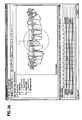
- FIG. 1is an illustration of an orthodontic care system incorporating a hand-held scanner system and treatment planning software in accordance with a representative embodiment of the invention.
- the hand-held scanneris used by the orthodontist to acquire three-dimensional information of the dentition and associated anatomical structures of a patient and provide a base of information for interactive, computer software-based diagnosis, appliance design, and treatment planning for the patient.
- the scanneris suitable for in-vivo scanning, scanning a plaster model, scanning an impression, or some any combination thereof.
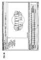
- FIG. 2is a block-diagram of a scanning system, suitable for use in the orthodontic care system of FIG. 1 .
- FIG. 3is a perspective view of a hand-held scanner used to acquire information of an object under scrutiny, suitable for use in the orthodontic care system of FIG. 1 .
- FIG. 4is an illustration of a patient being scanned with the hand-held scanner of FIG. 3 .
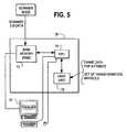
- FIG. 5is a block diagram of the back office server of FIG. 1 showing the elements used to calculate the digital model of the patient's dentition and display the digital model on a screen display of the back office server.
- FIG. 6is a screen shot displayed on the display of the back office server of FIG. 1, showing a graphical representation of a three-dimensional model of a patient's upper front teeth after a frame to frame registration.
- the useris applying landmarks to the teeth as a preliminary step in treatment planning, and as a step in registering overlapping segments of a scanned upper jaw relative to each other to calculate a complete model of the upper jaw and associated dentition.
- FIGS. 7A-7Fare a series of illustrations showing the generation of an individual tooth model from a scanned tooth, shown in FIG. 7A, and a template tooth, shown in FIG. 7B.
- a library of template teeth similar to FIG. 7Bare stored as three-dimensional computer models in computer memory.
- the individual tooth modelis a three-dimensional tooth object having a single set of points defining the boundaries of the tooth.
- the individual tooth modelreduces the amount of data required to represent the tooth, as compared to the data representing the tooth after a cumulative registration of a large number of frames.
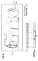
- FIG. 8is an illustration of the tooth model of FIG. 7D positioned in the computer model of the patient's dentition, surrounded by other anatomical structures.
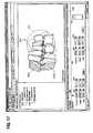
- FIG. 9is a screen shot from the treatment planning software showing some aspects of patient information that are stored in memory and accessed by the software, including photographs, patient information, examination notes, x-rays, medical and/or orthodontic or dental history, and the three-dimensional model of the malocclusion.
- FIG. 10is an illustration of a series of icons that appear on a screen display that provide some tools for viewing the three-dimensional model of the patient's dentition.
- FIG. 11is an illustration of a set of icons which are part of the screen displays which act as a navigational tool and allow the user to manipulate the three-dimensional models of teeth and brackets on the display.
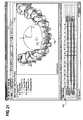
- FIG. 12is a screen shot from the treatment planning software showing a set of individual tooth objects representing the observed stage of a patient suffering from a malocclusion.
- FIG. 13is another screen shot from the treatment planning software, showing the observed stage and the placement of virtual three-dimensional brackets on the surfaces of the teeth.
- FIG. 14is another screen shot from the treatment planning software, showing several views of the observed stage and the fields by which an orthodontist can enter values to alter the relation of the upper jaw to the lower jaw as an initial step of planning treatment.
- FIG. 15is another screen shot showing several views of the malocclusion displayed simultaneously, similar to FIG. 14 .
- FIG. 16is a screen show showing a cross-section or “clipping plane” view through the upper arch in a target situation.
- FIG. 17is a screen shot illustrating of a portion of a target arch, showing a vertical cross-section or clipping plane taken through the teeth. This view is helpful in adjusting the relation between the upper and lower jaw.
- FIG. 18is a screen shot showing the placement of the virtual brackets on the teeth at the malocclusion, showing the user clicking on an icon to establish an initial archform for the upper arch.
- FIG. 19is a screen shot showing the computer model of the patient's teeth positioned in a target or desired stage, as a result of the user selecting an archform for the patient and the computer placing the teeth along the arch selected by the user.
- FIG. 19also shows the various parameters by which the orthodontist can adjust the shape of the arch, the distance between the teeth, the distance between the molars, and other parameters, so as to provide a unique and customized archform for the patient.
- FIG. 20is another screen shot showing the computer model of the patient's teeth in a target stage, also the brackets and the orthodontic archwire, and showing the numerous parameters available to the orthodontist to customize the tooth position, orientation, angulation, torque, and other parameters on a tooth by tooth basis for the target archform.
- FIG. 21is another screen shot showing a view of the target situation, with brackets and archwire, showing fields allowing the orthodontist to moving the teeth objects relative to each other in planning treatment for the patient.
- FIG. 22is a screen show showing a bracket offset correction being entered to move tooth number 16 into an improved occlusal relationship with the opposing jaw.
- FIG. 23is a screen shot showing the tooth movement that occurs with tooth number 16 when the bracket offset correction is made.
- FIG. 24is another screen show showing the target stage, with the brackets and archwire, showing a tooth moved in the buccal and coronal directions by an amount indicated by the orthodontist, and the correction incorporated into the archwire.
- FIG. 25is another screen shot showing a space management feature by which the target situation can be adjusted by specifying spaces between teeth or by extraction of teeth.
- FIG. 26is a screen shot illustrating the simulation of an extraction of a tooth number 41 .
- FIG. 27is a screen shot showing the user modifying the mesial gap between the teeth and showing how the user-specified mesial gap is instantaneously represented on the screen.
- FIG. 28is a screen shot showing the user modifying tooth position in a target stage on a tooth by tooth basis using a bonding correction feature.
- FIG. 29is a screen shot showing a wire tab, which allows the user to make changes in the shape of an archwire without changing bracket position.
- FIG. 30is a screen shot showing a wire offset tab, which allows the user to change thte the bend size, location, etc., in the wire.
- the present inventionprovides a dental treatment planning method and apparatus that allows for the design of virtually any configuration of tooth objects, bracket objects, wire objects and other appliances and objects.
- the treatment planning featuresis in the nature of a computer-aided design and computer-aided manufacturing (CAD/CAM) system that allows the user to identify treatment goals and to specify appliances that will achieve these goals.
- CAD/CAMcomputer-aided design and computer-aided manufacturing
- the present inventionprovides an interactive treatment planning system in which the tools are provided to the orthodontist to play an active role in diagnosis, treatment planning and appliance design.
- the orthodontistcan change the configuration for the archform, can correct individual tooth positions on the archform on a tooth by tooth basis, change the bracket position on the teeth, and can add additional bends in the archwire.
- the orthodontic treatment planningcan work with any three-dimensional tooth objects, regardless of their source.
- the three dimensional objectscomprise tooth objects obtained from a scanning of the dentition of the patient.
- the manner of developing these three-dimensional tooth objectsis described at length in the patent application of Rudger Rubbert et al. filed Apr. 13, 2001, entitled SCANNING SYSTEM AND CALIBRATION METHOD FOR CAPTURING PRECISE THREE-DIMENSIONAL INFORMATION OF OBJECTS Ser. No. 09/834,593, the contents of which are incorporated by reference herein.
- Other possibilitiesare 3-D models obtained from CAT scans, laser scans, ultrasound, 3-D photogrammetry of models, or other type of scanning taken either in-vivo or from a plaster model, or some combination of these techniques.
- the treatment planning systemalso uses three-dimensional objects comprising virtual models of orthodontic appliances, such as brackets and orthodontic archwires.
- the bracket modelscan be obtained as CAD models from bracket manufacturers, or from a scanning of the brackets themselves.
- the wire modelscan be derived from the cross-sectional shape and length of the wire, and parameters as to the shape of an arch that the wire is representing (including loops), as described below.
- other types of virtual three-dimensional objectsmay be used, such as retainers, Herbst appliances, the substantially transparent, removable aligning devices commercialized by Align Technologies, etc.
- the treatment planning that will be performed by the user for a given patientwill necessarily vary from patient to patient.
- the preferred embodiment of the treatment planning methodprovides a wealth of viewing, measuring, and simulation tools by which the orthodontist can plan treatment for any given patient.
- the treatment planning softwarewill be mainly described in terms of screen displays that are displayed on a user interface and the key functionality in the screen displays. A person skilled in the art will be able to program a computer to provide these functions from the present description and representative screen displays.
- the treatment planning softwarewill ordinarily be installed on a back office server or workstation in an orthodontic clinic.
- the softwaremay also be located in other clinics of related specialties, such as periodontal clinics, family dental clinics, and clinics of oral surgeons, so that the treatment planning, patient virtual model, and other parameters can be shared amongst multiple users.
- Some functionality of the softwaremay not be available or used where the software is distributed among multiple specialties. For example, the periodontist may not have any desire to change or modify tooth position or archwire shape.
- each clinic or officewith the scanning system described herein (or other suitable scanner), for treatment monitoring purposes, and so that when a new patient arrives at any of the clinics they can be scanned and the digital model shared with other specialties.
- the treatment planning softwarecould be installed at a remote site and some or all of the treatment planning done remotely, e.g, by a central service center, by a remotely located orthodontist, or by a precision appliance service center as described below.
- the three-dimensional model of the malocclusion and necessary patient informationis transmitted over a suitable communications link (e.g. the Internet) to the remote location.
- An orthodontist or other trained person operating the software at the remote locationseparates the teeth from the surrounding anatomical structures to create a set of independent tooth objects, studies the malocclusion and the treatment objectives for the patient, and uses the software to arrive at an initial proposed target situation for the patient.
- the initial proposed target situationis sent back to the orthodontist for review, modification, and/or approval.
- the modelcan be reviewed simultaneously and interactively with the patient, or shared with other specialists, or with a precision appliance manufacturing center.
- a copy of the digital model of the target situation(or of the malocclusion) is maintained on a central server at one location, such as the remotely located precision appliance manufacturing center.
- the usersaccess that copy of the model over the Internet and manipulate it using the treatment planning software described herein. All users that simultaneously participate in interactive, simultaneous manipulation of the model view the same thing.
- the copy of the model that is stored in the orthodontist's officeremains unchanged.
- FIG. 1is an illustration of an orthodontic care system 10 incorporating a scanner system 12 .
- the scanner system 12includes a hand-held scanner 14 that is used by the orthodontist to acquire three-dimensional information of the dentition and associated anatomical structures of a patient.
- the imagesare processed in a scanning node or workstation 16 having a central processing unit, such as a general-purpose computer.
- the scanning node 16either alone or in combination with a back-office server 28 , generates a three-dimensional virtual computer model 18 of the dentition.
- the computer modelprovides the orthodontist and the treatment planning software with a base of information to plan treatment for the patient.
- the model 18is displayed to the user on a monitor 20 connected to the scanning node 16 .
- the illustrated orthodontic care systemconsists of a plurality of orthodontic clinics 22 which are linked via the Internet or other suitable communications medium 24 (such as the public switched telephone network, cable network, etc.) to a precision appliance service center 26 .
- Each clinic 22has a back office server work station 28 having its own user interface, including a monitor 30 .
- the back office server 28executes an orthodontic treatment planning software program, described at length below.
- the softwareobtains the three-dimensional digital data of the patient's teeth from the scanning node and displays the model 18 for the orthodontist.
- the treatment planning softwareincludes features to enable the orthodontist to manipulate the model 18 to plan treatment for the patient.
- the orthodontistcan select an archform for the teeth and manipulate individual tooth positions relative to the archform to arrive at a desired or target situation for the patient.
- the softwaremoves the virtual teeth in accordance with the selections of the orthodontist.
- the softwarealso allows the orthodontist to selectively place virtual brackets on the tooth models and design a customized archwire for the patient given the selected bracket position.
- digital information regarding the patient, the malocclusion, and a desired treatment plan for the patientare sent over the communications medium to the appliance service center 26 .
- a customized orthodontic archwire and a device for placement of the brackets on the teeth at the selected locationis manufactured at the service center and shipped to the clinic 22 .
- the systemis applicable to other types of orthodontic appliances.
- a target situation for the dentitioncould be transferred to the precision appliance service center 26 .
- the center 26could make a stereolithographic (SLA) model of the dentition. From that model (or from models of the malocclusion), the center could fabricate removable orthodontic appliances such as transparent aligning devices, retainers, Herbst expansion devices, etc. using known techniques.
- SLAstereolithographic
- the precision appliance service center 26includes a central server 32 , an archwire manufacturing system 34 and a bracket placement manufacturing system 36 .
- These detailsare not particularly important to the treatment panning methods and apparatus and are therefore omitted from the present discussion for sake of brevity.
- the interested readeris directed to the patent application of Rudger Rubbert et al., filed Apr. 13, 2001, entitled INTERACTIVE AND ARCHWIRE-BASED ORTHODONTIC CARE SYSTEM BASED ON INTRA-ORAL SCANNING OF TEETH, Ser. No. 09/835,039, the contents of which are incorporated by reference herein.
- FIG. 2is a more detailed block-diagram of the scanning system 12 , suitable for use in the orthodontic care system of FIG. 1 .
- the scanning system 12is a mechanism for capturing three-dimensional information of an object 40 , which in the present example is the dentition and surrounding anatomical structures of a human patient, e.g., gums, bone and/or soft tissue.
- the scanning system 12includes a scanner 14 which is used for image capture, and a processing system, which in the illustrated example consists of the main memory 42 and central processing unit 44 of the scanning node or workstation 16 .
- the scanner 14includes a projection system 46 that projects a pattern onto the object 40 along a first projection axis 48 .
- the projected patternis formed on a slide 50 which is placed in front of a light source 53 .
- the light source 53comprises the terminus of a fiber-optic cable 51 .
- the cable 51carries a high intensity flash generated by a flash lamp 52 located in a base unit 54 for the scanner.
- a suitable flash lampis the model FX-1160 flash unit available from Perkin Elmer.
- the illuminations of the flash lamp 52cause the pattern contained in the slide 50 to be projected onto the three-dimensional surface of the object. Further details on the types of patterns suitable for the pattern are set forth in the following co-pending patent applications of Hindger Rubbert et al:, Ser. No.
- the scanner 14further includes an electronic imaging device 56 comprising an array of photo-sensitive pixels.
- a preferred embodimentis an off-the-shelf, color-sensitive, charged-coupled device (CCD) of a size of 1,028 ⁇ 1,028 pixels arranged in an array of rows and columns.
- CCDcolor-sensitive, charged-coupled device
- the Sony ICX205AK CCD chipis a suitable electronic imaging device.
- the electronic imaging device 56is oriented perpendicular to a second imaging axis 58 , which is off-set from the projection axis 48 .
- the angle ⁇ between the projection and imaging axesneed not be known in a preferred embodiment of the invention. However, if the 3D calculations are made in accordance with the parameters of FIG. 9, then the angle and the separation distance between the center of the imaging device 56 and the center of the light source 53 need to be known.
- the angle ⁇will be optimized during design and manufacture of the scanner depending on the desired resolution required by the scanner. This, in turn, is dependent on the degree to which the surface under scrutiny has undercuts and shadowing features which would result in the failure of the imaging device to detect the projection pattern.
- the greater the angle ⁇the greater the accuracy of the scanner.
- Angle ⁇is shown somewhat exaggerated in FIG. 2, and will generally range between 10 and 30 degrees for most applications.
- the electronic imaging device 56forms an image of the projection pattern after reflection of the pattern off of the surface of the object 40 .
- the reflected patterns imaged by the imaging devicecontain three-dimensional information as to the surface of the object, and this information needs to be extracted from the images.
- the scanning systemtherefore includes a processing subsystem which is used to extract this information and construct a three-dimensional virtual model of the object 40 .
- this processing subsystemconsists of a memory 42 storing calibration information for the scanner, and at least one processing unit, such as the central processing unit 44 of the scanning workstation 16 .
- the location of the memory and the processing unitis not important. They can be incorporated into the scanner 14 per se. Alternatively, all processing of the images can take place in the back office server 28 or in another computer. Alternatively, two or more processing units could share the processing in order to reduce the amount of time required to generate the three-dimensional information.
- the memory 42stores a calibration relationship such as a table for the scanner 14 .
- the calibration tablecomprises information used to compute three-dimensional coordinates of points on the object that reflected the projection pattern onto the imaging device.
- the information for the tableis obtained during a calibration step, performed at the time of manufacture of the scanner 14 .
- the calibration tableincludes an array of data storage locations that contain two pieces of information. Firstly, the calibration table stores pixel coordinates in X and Y directions for numerous portions of the projection pattern that are imaged by the electronic imaging device 56 , when the pattern is projected onto a calibration surface at two different distances during a calibration procedure. Secondly, the table stores distance information, (e.g., in units of tenths of millimeters), in X and Y directions, for the portions of the projection pattern imaged at the two different distances.
- distance informatione.g., in units of tenths of millimeters
- the scanning systemrequires at least one processing unit to perform image processing, three-dimensional calculations for each image, and registration of frames to each other.
- the processing unit 44 in the illustrated embodimentis the central processing unit (CPU) of the scanning work station 16 .
- the CPU 44processes the image of the pattern after reflection of the pattern off the surface of the object 40 and compares data from the image to the entries in the calibration table. From that comparison (or, more precisely, interpolation relative to the entries in the table, as explained below), the processing unit 44 derives spatial information, in three dimensions, of points on the object that reflect the projected pattern onto the electronic imaging device.
- Stray data pointsare preferably canceled out in generating the calibration table or using the calibration table to calculate three-dimensional coordinates.
- a smoothing functionsuch as a spline can be calculated when generating the entries for the calibration table, and the spline used to cancel or ignore data points that deviate significantly from the spline.
- FIG. 2also shows a few other features of the presently preferred scanning system 12 .
- the analog voltage signals from the device 56are amplified in an amplifier 57 and fed along a conductor 59 to an analog to digital converter 60 .
- the digital signalis converted into a bitmap stream of digital image data.
- the datais formatted by a module 61 into an IEEE 1394 “firewire” format for transmission over a second conductor 62 to the main memory 42 of the scanner work station 16 .
- the scanning systemincludes an optical scanner holder 64 for the user to place the scanner after the scanning of the dentition is complete. These details are not particularly important and can vary considerably from the illustrated embodiment.
- the scanning systemis constructed to provide a minimum of equipment and clutter at the chair side.
- the scanning stationis preferably located some distance away from the chair where the patient sits.
- the cable leading from the scanner 14 to the base station and/or workstation 16could be suspended from the ceiling to further eliminate chairside clutter.
- the scanning work station 16also includes the monitor 20 for displaying the scanning results as a three-dimensional model of the dentition in real time as the scanning is occurring.
- the user interfacealso includes a keyboard and mouse for manipulating the virtual model of the object, and for entering or changing parameters for the scanning, identifying sections or segments of scans that have been obtained, and other features.
- the scanning stationmay also include a foot switch, not shown, for sending a signal to the CPU 44 indicating that scanning is commencing and scanning has been completed.
- the base stationmay alternatively include a voice recognition module that is trained to recognize a small set of voice commands such as START, STOP, AGAIN, REPEAT, SEGMENT, ONE, TWO, THREE, FOUR, etc., thereby eliminating the need for the foot switch. Scanner start and stop commands from the CPU 44 , in the form of control signals, are sent to the light source 52 , thereby controlling the illumination of the lamp 52 during scanning.
- the light source 52operates at a suitable frequency, such as 6 flashes per second, and the frame rate of the CCD imaging device 56 is synchronized with the frame rate. With a frame rate of 6 flashes per second, and a scanning motion of say 1-2 centimeters per second, a large of overlap between images is obtained.
- the size of the mirror at the tip 68 of the scannerinfluences the speed at which scanning is possible.
- the illustrated embodiment of the mirror at the tip 68is 18 mm square. A larger mirror reflects more surface of the object and enables faster scanning. A smaller mirror requires slower scanning. The larger the mirror, the more difficult in-vivo scanning becomes, so some trade-off between size and utility for in-vivo scanning exists.
- the mirror 18is heated to prevent fogging during in vivo scanning by a resistance heater coil.
- the frame rate and permissible rate of scanner motionwill depend on many factors and can of course vary within the scope of the invention.
- a preferred frame ratewill be at least one flash per second. Flashing a high intensity flash lamp for a brief period of time is a preferred embodiment since it is desirable to reduce the exposure time of the CCD imaging device 56 to reduce blurring.
- a high intensity lampis desirable to achieve sufficient signal strength from the imaging device.
- a preferred embodimentuses 5 ⁇ sec flash times with similar exposure periods.
- An alternative embodimentwould use a constant illumination source of high intensity, and control exposure of the imaging device using a shutter, either a physical shutter or using electronic shutter techniques, such as draining charge accumulating in the pixels prior to generating an image. Scanning using longer exposures would be possible without image blur, using electronic image motion compensation techniques described in Lareau, et al., U.S. Pat. No. 5,155,597.
- FIG. 3is a perspective view of a hand-held scanner 14 used to acquire information of an object under scrutiny, suitable for use in the orthodontic care system of FIG. 1 .
- the projection system 46 and the electronic imaging device 56 of FIG. 2are contained in the housing 65 for the scanner.
- the housing 65is sized and shaped to be held in a human hand.
- the scanner 14includes an elongate distal portion 66 and a tip 68 .
- the tip 68is sized and shaped such that it can be inserted into and moved within an oral cavity of a human so as to enable scanning of anatomical structures inside the oral cavity.
- a heated mirror(not shown) is placed on the underside of the tip 68 to direct the projection pattern from the optics of the scanner onto the object and to direct the reflected pattern from the object towards the imaging optics associated with the electronic imaging device.
- FIG. 4is an illustration of a patient 70 being scanned with the hand-held scanner 14 of FIG. 3 .
- the checks and lipsare retracted from the teeth and the tip 68 of the scanner is moved over all the surfaces of the teeth in a sweeping motion at a velocity of perhaps 1-2 centimeters per second.
- the entire upper or lower jawmay need to be scanned in a series of scans, one for the left side, one for the right side, and one for the front. These individual scans are registered to each other to complete a registration of an entire upper or lower arch.
- Activation of the foot switch(not shown), or recognition of voice commands, indicates to the scanning processing system when each scanning segment is initiated and terminated. The entire process takes just a few minutes.
- the scanningcan be done in one continuous scan eliminating the need for scanning in segments and registering segments together.
- FIG. 5is a block diagram of the back office server of FIG. 1 showing the elements used to calculate the digital model of the patient's dentition.
- the back office server 28performs a cumulative registration process for the frames and ultimate generates and displays the digital model on a screen display 30 .
- the raw scanner data in the form of three-dimensional framesis stored in the main computer memory 72 .
- the frame data for N captured images from the scanneris stored in the hard disk 74 .
- the transformation matricesbasically contain information as to how each frame of three-dimensional points needs to be translated and rotated in a three-axis Cartesian coordinate system in order to be registered with the other frames in a best-fit manner.
- the hand-held optical scanner described hereinoffers numerous advantages, particularly it allows scans to be obtained in real time very quickly, i.e., in a matter of minutes.
- the scanscan be taken fully from the mouth or from a model, or from some combination of the two.
- the teeth in the modelare virtually extracted from the surrounding anatomical structures and represented as individual three-dimensional tooth objects.
- One way of performing thisis described below.
- FIG. 6is a screen shot showing a graphical representation of a three-dimensional model of a patient's upper front teeth representing one scan (segment 1 ) after a frame to frame registration.
- the useris applying landmarks 302 to the canine teeth as a preliminary step in treatment planning, and as a step in registering overlapping segments of a scanned upper jaw relative to each other to calculate a complete model of the upper jaw and associated dentition.
- the purpose of the landmarking shown in FIG. 6is to select a point on the canine teeth which is common to the front scan and the two side scans.
- the landmarkingis also done at a point on the labial surface of the teeth that would be a suitable location for placement of an orthodontic bracket as part of an appliance to correct a malocclusion.
- the userclicks on a tooth number, indicated by the row of numbers 301 , and drags the cursor with a mouse to the surface on the canine teeth where they wish to place the landmark. They then release the cursor, and the landmark 302 appears on the tooth.
- the landmarkhas an arrow 304 , which must point to the incisal edge of the tooth. The user can rotate the landmark to place the arrow in the proper orientation by simply clicking on the landmark and turning the mouse one way or the other. As each landmark is placed, a box below the tooth number is highlighted as indicated at 306 .
- the softwarecan place the landmarks automatically after the user has placed initially just two or three landmarks, preferably two landmarks at the molars and one of the front teeth. Having those landmarks, the system knows the general direction of the tooth axes, since tooth axes are generally parallel in most instances. The system also knows some idea of tooth widths as for most humans there is a fairly close relationship between the widths of the teeth. For example, someone with wide molars will as a rule have wide front teeth as well and thus the distance from the molar landmark to the front landmark will indicate the tooth width for the patient. So, the system will be able to make good guesses regarding tooth positions from this information.
- the landmarkscan slide along the surface of the dentition, we could after initial placement automatically slide the landmark along the surface of a tooth and detect the midpoint or center of the curvature of the labial tooth surface, which will come fairly close to where the landmark needs to be placed.
- the tooth numbering convention shown in FIG. 6is as follows: the first number indicates the quadrant of the patient's dentition, with 1 being upper right, 2 being upper left, 3 being lower left, 4 being lower right.
- the second numberis the tooth number in the quadrant with 1 being the incisor.
- the landmarks 302are placed at teeth 13 and 23 , the upper canines.
- the orthodontistconceptualizes teeth as individual teeth objects which can be moved independently of each other to correct the patient's malocclusion. Furthermore, orthodontists are trained to make physical models of the patient's dentition from an impression, cut the teeth from the model, and then individually move the teeth relative to each other to provide a target situation which corrects for the malocclusion. Therefore the back office server workstation preferably includes a software which enables the orthodontist to do this with the virtual three-dimensional model of the patient's dentition.
- the three dimensional model(resulting from a cumulative registration of frames) by separating the virtual teeth from the surfaces representing the gums and other anatomical structure, and presenting the crowns of the teeth to the orthodontist.
- roots of teeth from a template of three-dimensional template rootscan be associated with each tooth.
- the rootscould also come wholly or partially from 2-D sources such as X-rays of the roots, or from a 3-D source such as ultrasound or CAT scanner.
- the tooth separation processallows individual teeth to be moved independently in three dimensions on the computer in an interactive, user-specified manner, since they are individual three-dimensional objects. This process of separation of the teeth from the cumulative registration into individual teeth objects will be described next.
- the separation process described belowhas one further advantage, namely requiring less memory to represent an individual tooth. Cumulative registration may result in an extremely large number of points from a large number of frames to represent any given tooth.
- the separation process, as described below,reduces this data set to a single set of points that describe a single surface representing the surface of the tooth. Much less memory is required. Consequently, the treatment planning software can process treatment planning steps for the teeth more quickly.
- FIGS. 7A-7Fare a series of illustrations showing the generation of an individual tooth model from a scanned tooth. The process will now be explained in detail.
- FIG. 7Ashows the scanned dentition and associated anatomical structure surrounding the tooth 308 .
- This toothis tooth number 14 in the numbering convention shown in FIG. 6 .
- the back office server workstationstores a three-dimensional template tooth for each tooth in the maxilla and the mandible.
- the template tooth 310 for tooth number 14is shown in FIG. 7 B.
- the template tooth 310is a three-dimensional tooth object having a single set of points defining the boundaries of the tooth.
- the template tooth 310is positioned approximately in the same location in space as the tooth 308 .
- the landmark 302assists in providing the proper axial rotation of the template tooth to have it fit properly with respect to the tooth 308 .
- the template toothis placed at the point cloud of the dentition according to the labial landmark.
- the template toothcan be scaled larger or smaller or positioned arbitrarily by the user using object navigation tools, described below, in order to get a close a position as possible to the point cloud of the dentition.
- vectorsare drawn from the points on the template tooth to the scanned point cloud of the tooth 308 . Every ray intersects several surfaces, the number of surfaces depending on how often the respective part of the surface has been covered during scanning. For each vector, a surface is selected. Preferably, the smallest triangle surface is selected, since this surface corresponds to an image taken by the scanner when the scanner was positioned in a more perpendicular orientation to the surface, resulting in more accuracy in the determination of the coordinates of that portion of the surface. As another possibility, the outermost surface is selected, using a filter to insure that no extraneous surfaces are used. These points of the surfaces intersected by all the vectors are combined as newly generated triangle surfaces and therefore form one consistent surface shown in FIG.
- FIG. 7Fvirtual tooth object 312 .
- this generated object 312is then used as a template tooth, and the steps indicated by FIG. 7C, 7 D and 7 E are repeated in an iterative fashion. This is done to make sure that the algorithm works even if there are differences between the original template tooth and the scanned point cloud.
- an individual tooth object 312is then displayed to the user, as shown in FIG. 8 .
- the tooth object 312is displayed as a three-dimensional superposition of the original data (white) and the separated model of the tooth (darker tones). These tones allow the user to ascertain whether there is an even distribution of white and dark tones, indicating a good fit between the scanned tooth and the tooth template.
- the final resultcan also just be simply displayed for the user.
- This processis of course performed for all the teeth.
- the resultis a set of individual tooth objects for all the teeth in the patient's dentition.
- the teethcan be displayed either alone, or in conjunction with the surrounding anatomical structures such as shown in FIG. 8 .
- the virtual model of the patient's dentition, and the individual tooth objects created as explained above,provides a base for diagnostic analysis of the dentition and treatment planning.
- a bite registration scanis obtained from the patient at the onset of treatment to spatially correlate the scans of the upper and lower jaws when the dentition is clenched. This scan is used to provide a registration of the upper and lower jaw to determine the correct upper and lower relative position. This bite registration scan may be performed during treatment to monitor progress.
- the library of template teethcould be stored at a computer at the precision appliance service center.
- the clinicsforward the scan data of the malocclusion (either before or after a registration) to the appliance service center.
- a trained technician at the appliance service centeroperates the software described in conjunction with FIGS. 7A-7F on an appliance service center computer.
- the technicianprovides any required user input required by the software (such as checking the position of the template tooth relative the scan data and modifying the position of the template tooth). After the process is complete, a set of individual tooth objects is obtained.
- This set of tooth objects(data representing three-dimensional point clouds for all the teeth in the dentition) is sent back to the clinic 22 and stored on the back-office server 28 .
- the precision appliance service centercould also perform other treatment planning functions, such as, for example, generating an initial target situation for the teeth and forwarding it to the orthodontist for revision, initial bracket placement, etc.
- the individual teethWith the individual teeth now cut from the three-dimensional model of the dentition and represented as tooth objects, they can be moved relative to each other in three dimensions. Since orthodontics assumes that a bracket is fixedly bonded to a tooth, by moving the bracket one moves the tooth. The next step in the process is thus selecting an initial location to bond the brackets to the tooth. As noted below, this initial location can be adjusted by the treatment planning software.
- the spatial location of the surfaces of the bracket and the surfaces of the corresponding toothare known. Collision avoidance algorithms are used to keep the bracket positioned on the surface of the tooth and prevent the virtual bracket from entering the tooth itself, a clinically undesirable result.
- the useris able to move the bracket independently of the tooth by activating an icon (such as one shaped like a magnet to signify the mating of the bracket to the tooth). When the bracket is moved to the new location, the tooth matches up to the surface of the bracket.
- the bracketsare represented in the software as virtual three-dimensional objects, and the surface of all the brackets and the teeth are known in three dimensional spatial coordinates. Accordingly, collision detection algorithms are employed to detect when simulated tooth or bracket movement would result in a collision between brackets and teeth. Similar collision algorithms are provided to prevent the adhesion surface of the bracket from migrating into the body of the virtual tooth object and to keep the brackets located on the surface of the teeth. IF the user wishes to move the location of the brackets, the movement of the teeth follows the movement of the bracket. Also, again since the bracket is a three-dimensional virtual object with known spatial coordinates, the user is provided with a tool (such as an icon) which when activated allows the user to move the bracket about one plane or axis, and freeze the movement in the other directions.
- a toolsuch as an icon
- Initial virtual bracket placementis done as follows. Landmarks 302 such as shown in FIG. 6 are placed on the labial surfaces of all the teeth. The landmarks are placed at the location where the orthodontist expects to place an orthodontic bracket to correct the malocclusion. The bracket shape is shown on the monitor. Three-dimensional templates for a variety of commercially available brackets are stored in memory and the software asks the orthodontist to select a particular manufacturer and style of bracket to use with the patient. Thus, as the landmarks 302 are placed, virtual brackets appear in the computer model on the labial surfaces of the teeth where the orthodontist desires to place the brackets.
- the orthodontistcan move the bracket position depending on the type of forces the orthodontist wishes to create on teeth to correct the malocclusion. Because the brackets are individual objects and stored in memory, when they are placed on the surface of virtual teeth complete position information is known in three dimensions. As such, the brackets can be displayed either alone, or in conjunction with teeth, or hidden from view, by means of appropriate user specified commands on the user interface. For example, the screen display showing the target or current stage can have an icon indicating hide brackets, or display brackets, and activating the icon causes the brackets to be hid or displayed. The same is true for other virtual objects that exist independently of other objects, such as tooth models and the archwire.
- FIG. 12is a screen shot showing a three-dimensional model 18 of a malocclusion, showing the teeth 312 in both the upper and lower arches 326 and 328 , respectively.
- the screen 330includes a row of icons 332 across the upper portion of the display, which are associated with various tools available to the user to view the dentition, virtual brackets, and current and target archforms.
- the lower portion 334 of the screenincludes a set of tabs 336 that are accessed in various aspects of treatment planning. These tabs 336 include a patient tab 338 , which accesses the screen of FIG. 9.
- a limits tab 340allows a user to breakdown the tooth movement between observed and target stages into stages, such as 30 percent, 50 percent and 75 percent, and display the tooth positions for both arches at these positions.
- a differences tab 342quantifies the differences (in terms of translation and rotation) between the observed and target stages for each tooth.
- the space management tab 344permits the user to simulate extraction of one or more teeth and adjust the spacing between teeth in either arch.
- a bonding correction tab 346allows for adjustment of tooth position to be realized via bonding corrections.
- the technique tab 348allows the user to select a bracket prescription and default settings for bracket height (distance from bracket slot to incisal edge of tooth). The tab also displays the parameters for the bracket prescription chosen by the user.
- the upper/lower (U/L) relations tab 327selected in the screen shot of FIG.
- the tabsalso include a bracket offset tab 352 that allows a user to reposition the bracket on a tooth and specifies numerical values for each bracket placement modification.
- a brackets tab 354allows a user to enter information as to the type or manufacturer of brackets for each tooth in the both arches.
- a further “morphing” tabcould be provided which would animate the movement of the teeth from malocclusion to target situations based on treatment steps or limits defined by the user (explained in further detail below).
- the screen shot of FIG. 12also includes a region 356 that allows the user to navigate between views of the observed stage and views of the target stage.
- the userhas highlighted or selected both arches in the observed stage, so the screen display shows the model of the dentition in the current or observed stage.
- the treatment planning softwarepreferably displays a plurality of icons 331 , not all of which are shown in FIG. 12, to enable the user to quickly and easily view the three dimensional model in various standard perspectives.
- the icons 331 of FIG. 10include icons 333 , 335 , 337 and 339 for viewing the dentition in top, bottom, right hand side and left hand side views, respectively.
- An icon 341is provided which zooms in or out. Icons 343 and 345 allow the user to select for viewing just the upper or lower arches, respectively, including virtual teeth, virtual brackets and virtual archwire.
- the icon 347allows the user to show or hide the virtual dentition, excluding brackets and archwires.
- An icon 349allows the user to select or deselect the virtual brackets.
- a marker icon 341is used for measurement functions (described below) and an object navigation icon 353 is used for manipulating any of the virtual objects on the screen.
- the camera navigation icons of FIG. 10move all the elements together.
- the initial placement of the virtual brackets 400can be displayed along with the teeth.
- the camera navigational toolsallow the user to zoom in an zoom out in any desired degree.
- the virtual teeth 312 and virtual brackets 400are individual three-dimensional objects which can be selected and moved independently.
- One way of moving objectsis by entering new positional values (e.g, in terms of mm of displacement or angle of rotation, as described later).
- Another method provided by the softwareis using object navigational controls, activated by clicking the icon 353 or by accessing the function via a tools menu.
- the object navigation controlsallow the user to move the object based on orthodontic judgment and visual feedback.
- the amount of movementis stored and can be displayed using numerical position information.
- the bracket positioncan be individually adjusted on a tooth by tooth basis.
- the camera navigation iconspermit navigation of the archforms (i.e., the teeth placed on some selected archform), navigation of the brackets, or navigation of the archwire.
- the object navigation toolsfirst require an object (e.g., tooth, bracket, archwire, etc.) to be selected.
- an objecte.g., tooth, bracket, archwire, etc.
- the userplaces the cursor over the object and double clicks the mouse.
- the selected objectis highlighted in a separate color. Additional objects are selected by pressing and holding down the ⁇ CTRL> button while double clicking additional objects.
- the objectis selected as described above and the icon 341 is clicked.
- the softwareprovides an object navigation icon 353 .
- object navigational toolsappear on the screen 330 .
- These navigational tools 355are shown in FIG. 11 and FIG. 12 .
- the object navigational tools 355comprise a large circle 357 , a small circle 359 and a small rectangle 361 .
- the objectis selected as described above.
- the object navigation icon 353is clicked, activating the tools 355 such that they are displayed.
- the userpositions the mouse pointer relative to the tools 355 and presses and drags as described below to position the object.
- the mouse pointeris outside the large circle 357 , when they start dragging the object is turned either clockwise or counterclockwise depending on the direction of dragging.
- the icon 351allows the user to establish a measurement marker on any portion of the virtual model of the dentition.
- the useruses the icon 351 to place markers at any two points on the dentition and the distance between the markers is displayed on the screen.
- a tool in the Tools menu inincludes a DELETE ALL MARKERS function to delete the markers.
- the measurement functionallows the user to measure tooth size, inter-molar width, inter-canine width, the arch length, curve of spee, and other important orthodontic and diagnostic parameters.
- the measurement aspect of the inventionis particularly significant in that it permits precise quantification of simulated tooth movement, both in terms of establishing initial treatment plan as well as monitoring treatment.
- the viewing optionsalso include a clipping plane feature by which cross-sections of the teeth through any desired plane are possible.
- the clipping planeis shown through the upper jaw, but the user at can move this plane in three-dimensional space at will. If the teeth are magnified, this clipping plane feature is very useful for inspecting contact points between the upper and lower jaw, viewing and adjusting the upper and lower jaws in the initial bite registration, and adjusting the location of the occlusal plane.
- the clipping planeis shown through the upper and lower incisors 312 A and 312 B.
- the clipping planeis manipulated like an object with the object navigational tools shown in FIG. 11 .
- the planeis accessed using a tools menu and the user highlights or selects SHOW CLIPPING PLANE.
- a planeappears on the screen.
- the userclicks on the object navigation icon 353 (FIG. 10 ).
- the object navigational controls 355 of FIG. 11then are displayed.
- the userpositions the mouse pointer over the navigational controls 353 to adjust the position of the clipping plane.
- the planeWhen they start dragging in the region outside the large circle 357 (FIG. 11, FIG. 16 ), the plane is turned clockwise or counterclockwise. Then they start dragging inside the large circle 357 , the plane is rotated in the direction indicated by the dragging.
- the clipping planeis moved in the direction of the dragging.
- they start from inside the rectangle 361if they drag up they cut less into the model, by dragging down they cut further into the model.
- the first step in typical treatment planningis deciding where to place the teeth in three-dimensional space. This will ordinarily involve a definition or fixation of the vertical level of the teeth relative to the bones, and defining an occlusal plane, and adjusting the occlusal plane sagittally and transversely. This, in turn, will ordinarily involves an assessment of structural relationship between the teeth and the maxilla and mandible.
- the orthodontistperforms this by accessing and studying x-ray, CAT scan, photographs or other two dimensional data stored in the patient records portion of the treatment planning software, and of course the three-dimensional model of the malocclusion, with the teeth either represented as individual tooth objects or in context with the surrounding anatomical tissue.
- the mid-sagittal profile of the incisors and molarsis set up by superimposing the mid-sagittal plane of the teeth over the x-ray.
- FIG. 9is a screen shot from the workstation running the treatment planning software showing a patient information screen.
- the screenincludes a region 500 for storing various photographs 502 of the patient's head and face, and various views of the patients dentition. The photographs are taken with a digital camera and loaded into the workstation, and accessed from the treatment planning software.
- the patient information section of the softwarealso includes separate screens for entering and displaying other pertinent information for the patient, accessed through a menu 504 . These additional screens (not shown) include the patient demographics, patient medical, dental and orthodontic history, examination notes, and x-rays.
- the treatment planning softwareprovides the ability to view and adjust the initial bite registration.
- the initial bite registration between the upper and lower archescan be modified using the U/L relation tab 327 of FIG. 12 .
- the usercan move or rotate the lower jaw relative to the upper jaw by entering values in the field 366 .
- the usercan also simulate a chewing motion of the upper and lower jaws by moving the slide bar 368 down. During this simulation the lower jaw moves from side to side and up and down to simulate a chewing motion.
- FIG. 14shows how the three-dimensional viewing area on the screen on the workstation can be broken up into separate screens using known windowpane techniques.
- windowpane 360the area of the molar in the observed stage is displayed, with the orthodontist able to assess the upper and lower relation and change values for the upper and lower relation in three planes of space.
- windowpane 362shows the upper and lower jaws as seen from above.
- Windowpane 364shows the dentition looking from the molars out towards the incisors, a view the orthodontist would otherwise not be able to access without the three-dimensional virtual model.
- FIG. 15is another screen shot showing the three-dimensional model of the dentition in the observed stage. No values have been entered in the malocclusion field 366 in the U/L Relations tab. By inspection of the upper and lower jaws (using magnification or clipping plane features if needed), the user can set numerical values in field 366 and immediately simulate the corresponding tooth movement to arrive at a desired upper and lower initial bite registration.
- the next stepis selection of a desired or target archform for the patient and the midline.
- the orthodontistwill have previously selected or indicated a general type of archform for the patient, e.g, Roth.
- the treatment planning softwareallows the user to generate a target arch based on this archform for the individual patient.
- the userhighlights the observed stage in region 356 and then right clicks the mouse.
- the pop-up menu 370appears and the user selects INSERT TARGET STAGE.
- the target stageis arrived at by creating a flat virtual wire that runs through the virtual bracket slots to create a virtual arch line.
- the arch shapeis based on the user's selected preference for the arch shape, based on the patient's facial anatomy, bone structure, malocclusion, and other parameters using the orthodontist's judgment.
- the wire target shapehas a best fit through the malocclusion bracket slot positions. In one embodiment this wire is flat. It is also possible to design the wire to adapt to the malocclusion in the vertical direction to create a Curve of Spee if desired.
- the geometry in the transverse directioncan also be changed, such as the transverse curve of Monson establishing an inclination of the teeth in the coronal plane.
- FIG. 19is a screen shot from an orthodontic workstation showing the computer model of the patient's teeth objects 312 positioned in a target or desired condition.
- the illustrationis the result of the user selecting an archform for the patient from a known type of archform and the computer placing the virtual brackets along the arch selected by the user. This is executed by placing or threading the virtual brackets along the archform or curve selected by the orthodontist.
- the bracketsare omitted from FIG. 19, but are shown in FIG. 20 .
- the slide line tab shown in FIG. 10is activated.
- the initial target archform presented to the user in FIG. 19is only an initial archform.
- the treatment planning softwareallows the orthodontist to change many variables in the target situation, simply by entering new values in the slide line area 402 of the screen display.
- FIG. 19shows some of the parameters by which the orthodontist can adjust the shape of the arch, including the distance between the cuspids, the distance between the rear-most molars, the center line offset, and the radius of curvature at the front of the teeth.
- Slide line areaalso permits the user to select a symmetrical archforrn or an asymmetrical archform, and apply corrections on the right and left quadrants as indicated.
- the shape of the archformis instantaneously modified on the screen display, allowing the user to simulate various potential archform configurations for the patient.
- the userwill ordinarily set up the lower arch first.
- the upper archis automatically derived from the lower arch.
- the usercan view the arch forms in several ways using three arch icons 390 , 392 and 394 .
- the arch icon 390is for the malocclusion arch, which causes a blue line to appear on the screen which exhibits the curvature of the observed arch or malocclusion.
- the linepasses through the slots on the virtual brackets, as placed on the teeth.
- the arch icon 392is for the target arch, which represents a custom archwire passing through the bracket slots of the teeth in the target situation.
- the line 396 in FIG. 19represents this arch.
- the arch icon 394if for an ideal spline or curve generated by the software to represent an optimal shape.
- the archretains a parabolic shape as the user manipulates the target arch using the entries in the slide line.
- the numerical values in region 398 of the slide line tabrepresent checkpoints and boundary conditions on the ideal spline associated with the icon 394 . These values can be edited as indicated.
- the difference between the two archformsindicates the space needed to control arch length inadequacy; i.e., to identify the need for interproximal reduction, extraction, or control of gap size.
- Interproximal reductioncan be achieved by the clipping plane feature, and the simulation of shaping of individual tooth objects in three planes of space. The simulation of extractions and control of gap is provided for as explained later.
- the treatment planning softwareprovides a space management tab 344 that is used for managing space between teeth, including tooth extraction.
- FIG. 25is a screen shot showing the target situation of both the upper and lower jaws. The user clicks on the space management tab 344 , and the region 420 of the tab appears.
- the region 420allows the user to simulate the extraction of a tooth in either the current or target stage. Here the user is simulating the extraction of tooth number 41 by clicking on the appropriate cell for that tooth in the rows for current and target stages.
- the resultis shown in FIG. 26 .
- the extraction of tooth 41is simulated.
- the region 422also allows the user to enter values for the mesial gap size between teeth. A default value of 0.1 mm is provided. However, the user can change these values.
- the usercan enter any values in the row of cells for mesial gap size as shown in FIG. 27 (in this example 2 mm). Note also in FIG. 27 that the simulation of the extraction of tooth 41 is not being performed since the cell 423 is not checked.
- the toothmoves distally if a positive number is typed in the cell for that tooth in the mesial gap size row 424 . If a negative number is typed into the cell, the tooth moves mesially.
- the usermay wish to adjust the position of the virtual brackets 400 on the teeth.
- the step of adjusting the virtual bracket positioncan also be performed prior to the design of the archform.
- the vertical position of the virtual brackets relative to the incisal edge of the virtual teethis one adjustment that can be made. This distance can be measured using the measurement tool described earlier. Bracket manufacturers have recommendations for this distance. If the initial landmarking has placed the brackets outside of the recommended distance, this distance can be adjusted by using the object navigational tools. Alternatively, the user can select preferred values for the archform and the bracket set (bracket manufacture, bracket technique and wire type, e.g., straight) and the landmarks and virtual brackets will be placed on the teeth at the recommended distance.
- the bracket placementcan also be performed interactively by the user.
- the userlooks at every tooth 312 one by one (using a screen such as the screen shot of FIG. 18) to see if they are basically satisfied with the bracket 400 position, e.g., angulation, side to side position, and its relation to teeth in the opposing jaw.
- the usermay be performing this step while viewing the malocclusion, or the target stage.
- the userselects the bracket, zooms in if necessary, and adjusts the position of the bracket on the tooth surface using the navigational tools as described earlier.
- the usercan adjust the individual tooth position on a tooth by tooth basis in the target arch.
- thiscan be performed.
- the usercan use the tables in the Target Correction tab. See, for example, FIG. 21, in which the user has entered a value of ⁇ 15 degrees for rotation of tooth number 41 , and the tooth is rotated by that amount. The correction is realized by a bend in the archwire 396 .
- the bracket position on the toothdoes not change in this example.
- the target corrections tab 410permits any values to be entered for mesial, buccal and coronal translation in three planes of space, and torque, angulation and rotation movements about three orthogonal axis.
- independent tooth position correctionsare available in 6 degrees of freedom for every tooth, merely by entering values in the tables in the target corrections tab 410 .
- FIG. 24Another example is shown in FIG. 24, in which a new target position is shown for tooth number 41 .
- the usercan move teeth using the Bonding Corrections tab 346 of FIG. 12 .
- An exampleis shown in FIG. 28 .
- the bonding corrections tab 346allow the user to enter new values for tooth position for any tooth in the arch by merely entering values in the appropriate cell.
- the selected tooth 312 A(tooth number 41 ) is moved as indicated (here, a new rotation value of ⁇ 16 degrees is entered).
- the virtual bracketremains in the same location in space and the gap 412 between the pad of the bracket and the surface of the tooth is taken up by a bonding adhesive when the bracket is bonded to the tooth.
- Examples of common tooth movements that can be simulated using the bonding corrections tab or the target corrections tabare moving the lower incisors buccally or lingually, inclining the incisors axially, and leveling the incisors.
- the usercan simulate tooth position corrections interactively using the navigational tools.
- the userdisplays a target stage as needed.
- a tooth objectis selected as explained above.
- the userclicks on the zoom icon 341 of FIG. 10 to zoom in or out as needed.
- the userclicks on the object navigation icon 353 to display the object navigation controls.
- the userthen uses the navigation controls to move the tooth as desired.
- the movement of the toothis recorded as new values in the bonding correction and target correction tables, in case the user wants to quantify the movement or use those tables for further modification of the tooth position.
- After the user has moved the tooth to the new positionthey click one of two check mark icons 414 , 416 (FIG. 20, 21 ) that are highlighted on the screen.
- the blue check mark 414realized the new tooth position via a bonding correction.
- the red check mark 416realizes the new tooth position via a wire correction.
- FIGS. 22 and 23Another example of correction of individual tooth position is shown in FIGS. 22 and 23.
- the target situationis shown, both with the virtual tooth objects 312 and the virtual brackets 400 .
- tooth 16312 A
- the orthodontistcan correct this gap by building in a bracket offset, basically repositioning the location of the bracket 400 on the tooth 312 A by entering an amount in the table 450 in the angulation cell for tooth number 16 (here ⁇ 15 degrees).
- the resultis shown in FIG. 23 .
- the change in the angulation valuecauses tooth number 16 to rotate back into a more desirable occlusion with the opposing tooth.
- the wire tab 432 of FIG. 29allows the user to make wire configuration changes, while not changing bracket position.
- the virtual wire 396is shown isolated from the teeth and brackets.
- the virtual wirecan be scaled to actual size and printed out and provide a template for a manual bending of a wire if the orthodontist chooses not to obtain a wire from the precision appliance manufacturing center.
- the tabincludes a section 430 where the user can view the distance in mm in which the wire will slide relative to the brackets, on a tooth-by-tooth basis, when the teeth are moved from the current situation to the target situation. Note that a collision is detected for tooth 22 in movement of the tooth from the current situation to the target situation. This can be resolved in several possible ways in accordance with the teachings of U.S. Pat. No. 6,250,918 to Sachdeva et al., the contents of which are incorporated by reference herein.
- the wire offsets tab 426allows the user to simulate bending a wire 396 to the corrected tooth position while simultaneously retaining the original bracket position. Note that in FIG. 30 the wire 396 is flat with no corrections indicated. The user highlights one of the teeth in the virtual model and enters new values for tooth position. The change is reflected in a new shape for the wire 396 .
- the tabalso allows the user to build in over/under compensation into the archwire. These settings do not affect the bracket position.
- the characteristics of the wire bends, such as the radius of curvature,can be controlled by accessing a slidings tab (not shown).
- Another tab, forces 428displays approximations of the forces the wire applies to each tooth to displace it from its initial position to the target position.
- the treatment for the patientcan be broken up into segments or stages with each stage defined arbitrarily.
- the orthodontistcan specify a first treatment stage as the movement of the teeth from the initial position half-way to the final position.
- the softwareincludes a screen that permits the user to view the position of the teeth when moved to the half-way position. Basically, the simulation simply multiplies the differences in tooth position between initial and target stages by 0.5 and the resulting tooth positions are displayed on the workstation. Additionally, the user can specify further intermediate positions, such as one fourth or three fourths.
- the orthodontistcan monitor treatment and compare the progress of the treatment with the limits or stages that have been set.
- the patient's dentitionis scanned.
- the three-dimensional model of the now current situationis compared with the defined stages and perhaps with the target situation. Difference between actual progress and the planned treatment can be quantified.
- Changes to the archwirecan be designed using the treatment planning software to move the teeth in the desired direction to account for unexpected biological influences that may be observed.
- treatment planninghas been predicated on the use of a three-dimensional model of the dentition from the scanner, obtained as described above.
- digital treatment planningby importing into the software three-dimensional software from other sources.
- three-dimensional modelscan be exchanged with different software programs in different file formats, similar to the translation programs that convert text documents from one type of file (e.g., Microsoft Word to WordPerfect).
- Most three-dimensional applicationshave several import filters for different 3D formats.
- a 3D file that holds 3D data in a surface descriptionconsists typically of triangles that form the surface of the object.
- the STL formatis one of the oldest and therefore most common formats that uses triangles. It is used to feed information to stereolithography machines. A more detailed description of STL can be found at http://www.mmsonline.com/artciles.019704.html, the contents of which are incorporated by reference herein.
- Interactive, computer-based treatment monitoringis a significant advantage provided the treatment planning and appliance design aspects of the system described herein.
- the patientwhen they comes into to the office during treatment, they will be scanned and a new digital model of the dentition is acquired. From this new model, differences can be monitored between the current situation and the original malocclusion, and differences between the current situation and the target situation or pre-defined limits or treatment stages as defined earlier. These differences can be quantified with precision. For example, a point on the tooth in the current model is selected, and the model of the tooth at the original malocclusion is overlaid on the screen. The superposition of the two teeth allows the user to view the change in position that has occurred.
- the measurement marker features described earlierallow the user to quantify precisely the amount of movement.
- any deviations between the therapeutic result that is observed and the expected resultcan be captured precisely and at an early stage in treatment using the scanning and treatment planning features described herein, and corrected for.
- the orthodontistmay need to place additional bends in the archwire.
- additional bendscan be performed by simulating the wire shape on the screen, displaying the wire only on the screen, and printing out the screen and using it as a template for bending the wire.
- the current situationcould also be forwarded to the precision appliance center for manufacture of a new appliance.
- these monitoring and treatment correctionsare applicable to any type of appliance selected for the patient.
- the appliance that is manufactured in accordance with the treatment planned for the patientcan vary within the scope of the invention and will depend on the application, including the type of appliance desired by the orthodontist and the patient.
- the treatment planning and simulation features described abovecan be used in wide variety of treatment regimes, including flat wires and brackets, finishing wires, retainers, Herbst devices, expansion devices, and removable, transparent aligning devices such as those furnished by Align Technologies.
- the movement of the teeth from the current or observed stage to the target or treatment stagecan be broken into a series of movement steps.
- the position of the teeth in that stageis known by virtue of the manipulation of the individual tooth models in the treatment planning software. These tooth positions can be used to manufacture the aligning devices.
- the results of the treatment planning softwareare used to generate a customized orthodontic archwire and a bracket placement tray for precise placement of off-the-shelf brackets onto the patient's teeth.
- the treatment planning softwarewill store the following information (in addition to the patient records):
- brackets1) the placement location of the brackets on the malocclusion, including the type and dimensions of the brackets;
- the target situationincluding the location of the teeth and brackets in three dimensions at the target situation.
- the above information from the treatment planning softwareis sent over a suitable communications medium 24 in digital form to the precision appliance service center 26 .
- the service centermanufactures a customized archwire and a bracket placement tray for placement of the brackets at the intended location on the teeth in the malocclusion.
- the position of the bracket slots, and the shape of the brackets, when the teeth are in a target situationis information that is ultimately developed and stored by the treatment planning software.
- This position of the bracket slots and the shape of the slot(e.g., the length) is of course known in three dimensions. From the slot shape, it is possible to derive a three-dimensional set of line segments that represent the shape of an archwire passing through the bracket slots in the target situation, and calculating the optimal shape of bends that connect the bracket slots together.
- the positions of the straight sections and the bendsare fed as an input file to a wire bending robot.
- the wire bending robotneed only know the wire size, the shape and size of the slots, and the positions of the slots in the target situation. From this information, robot commands are generated to bend the archwire into the desired shape.
- the bracket placement trayis separately manufactured using stereolithography or other similar technique.
- the treatment planning softwaregenerates items 1) and 2) above, and superimposes the brackets on the teeth to generate a three-dimensional model comprising the three-dimensional tooth objects plus the virtual brackets at their intended locations in the observed stage or malocclusion.
- This three-dimensional modelis supplied to a stereolithography (SLA) instrument.
- SLA instrumentmanufactures a plastic model of the teeth with the brackets superimposed on the teeth.
- a thermoplastic foilis placed above the SLA model and the model and foil are placed within a pressure chamber. The chamber is pressurized so that the foil envelops the dentition and the brackets. After cooling, the foil is removed from the model.
- the foilnow in the shape of a transfer tray, has small indentations where the brackets are located. Real brackets are placed in these indentations.
- the orthodontistuses indirect bonding techniques to bond the brackets to the teeth.
- the transfer traypositions the brackets on the teeth at the desired location. After the bonding is complete, the orthodontist removes the transfer tray, resulting in the brackets bonded to the teeth at the desired location.
- a further scan of the dentitioncan be made at this step to verify the position of the brackets. Any substantial deviation in the bracket position can be accounted for by modification of the archwire, again using the treatment planning features described above.
- bracket basethe part bonded to the tooth
- tooththe part bonded to the tooth
- an off-the-shelf bracketwill never precisely match the individual tooth of any given patient.
- One optionis to fill the gap using a surplus of bonding adhesive during bonding.
- Another optionis to equip the base of the bracket with a customized pad made from an adhesive.
- Customized bracket padscan be manufactured using a variety of techniques.
- One possibilityis to bond a blob of adhesive to a bracket base, and mill the blob using a milling machine to match the tooth surface. Since the tooth surface is known precisely from the scanning, and the position of the bracket base relative to the surface is also known precisely, a very accurate bracket pad can be manufactured in this fashion.
- Another techniqueis to stamp out a bracket pad using stamping machine either in the desired shape or as a blank and milling the stamped pad to the desired shape.
- a third possibilityis creating a negative of the customized pad, forming the pad in a mold, bonding the pad to the bracket and the orthodontist trimming the pad as necessary when the pad is bonded to the tooth.
- a scan of the bracket placementis made. The scan is compared to the digital template of the expected bracket position. If the bracket is placed incorrectly, the bracket can be re-bonded to the tooth. Alternatively, corrections to the wire may be made if necessary to account for displacement of the brackets from their expected position. Basically, this is done by simulating the position of the teeth with the actual bracket placement at the target situation and correcting the shape of the archwire as necessary, or obtaining a new archwire based on the actual placement of the brackets.
- a transfer traywithout the intermediate step of a positive SLA model representing the dentition and the brackets.
- These traysmay be either similar to the plastic sheets and just be fabricated using rapid prototyping methods (SLA, laser sintering, milling, 3-D printing, etc.), or they have more sophisticated geometry including features to hold the brackets and features to provide proper positioning at the dentition.
- bracket placement jigscan be milled from the three-dimensional models of the dentition and the brackets using techniques described in, for example, in the Andreiko patent cited earlier.
- the customized bracket bonding pads based on the virtual tooth/bracket geometrycan be fabricated.
- Such bonding padsmay include additional material which conforms to the surface of the tooth to act as a placement jig for the tooth to allow the bracket bonding pad to be precisely located on the tooth. Then the bracket is bonded to the bracket bonding pad. The additional material is then removed.
- the treatment planning softwarepermits the placing of brackets onto tooth models in an arbitrary manner and virtually “bonding” those brackets to the teeth so that they move together. While the present embodiment has described a landmarking feature by which the user places landmarks on the teeth and the brackets are placed on the landmarks, this may be performed in other ways, including automatically with no user involvement based on parameters such as crown height, bracket type, tooth size, etc.
- the softwarealso provides for aligning of the brackets along virtual wire of any shape.
- the bracketsfollow this shape, thereby indicating tooth position correction in the target situation.
- This featureallows the user to drive the treatment planning based on wire shape.
- the wire shapecan be dictated by the placement of the brackets on the teeth.
- the treatment plancan be one driven by bracket placement. Obviously, wide variety is possible in the shape and design of the wire.
- the softwareprovides for a wide variety in defining the maxillary/mandible relationship, the occlusal plane and the mid-line of the teeth.
- Another significant aspect of the softwareis that it provides for virtually unlimited 3D measuring features using the marking icon and measurement feature described earlier. This feature offers a powerful diagnostic tool, as well as a tool for monitoring the progress of treatment and quantifying results.
- the point cloud representing tooth objectsdefines a surface, when surfaces come in contact during the tooth movement a collision is simulated. This collision is detected by suitable collision detection algorithms.
- the usercan be notified of the collision and resolve the conflict between teeth, for example by selecting one tooth as a primary tooth and moving that tooth first in an initial stage of treatment, and then moving the other tooth in a secondary stage of treatment.
- Another advantage of the instant treatment planning softwareis that it offer the user real time simulation with immediate feedback on the effect of user specified tooth movement.
- resultsare displayed immediately.
- the systemoffers arbitrary access to every object, including election, navigation and export.
Landscapes
- Health & Medical Sciences (AREA)
- Oral & Maxillofacial Surgery (AREA)
- Dentistry (AREA)
- Epidemiology (AREA)
- Life Sciences & Earth Sciences (AREA)
- Animal Behavior & Ethology (AREA)
- General Health & Medical Sciences (AREA)
- Public Health (AREA)
- Veterinary Medicine (AREA)
- Physics & Mathematics (AREA)
- Optics & Photonics (AREA)
- Dental Tools And Instruments Or Auxiliary Dental Instruments (AREA)
Abstract
Description
Claims (45)
Priority Applications (17)
| Application Number | Priority Date | Filing Date | Title |
|---|---|---|---|
| US09/834,412US6632089B2 (en) | 1999-11-30 | 2001-04-13 | Orthodontic treatment planning with user-specified simulation of tooth movement |
| US10/428,461US7717708B2 (en) | 2001-04-13 | 2003-05-02 | Method and system for integrated orthodontic treatment planning using unified workstation |
| US10/620,231US7156655B2 (en) | 2001-04-13 | 2003-07-14 | Method and system for comprehensive evaluation of orthodontic treatment using unified workstation |
| US10/684,252US7585172B2 (en) | 1999-11-30 | 2003-10-09 | Orthodontic treatment planning with user-specified simulation of tooth movement |
| US10/791,440US7296996B2 (en) | 1999-11-30 | 2004-03-02 | Virtual bracket placement and evaluation |
| US11/133,996US8021147B2 (en) | 2001-04-13 | 2005-05-20 | Method and system for comprehensive evaluation of orthodontic care using unified workstation |
| US11/600,612US8177551B2 (en) | 2001-04-13 | 2006-11-16 | Method and system for comprehensive evaluation of orthodontic treatment using unified workstation |
| US12/110,253US8465280B2 (en) | 2001-04-13 | 2008-04-25 | Method and system for integrated orthodontic treatment planning using unified workstation |
| US12/728,972US8469705B2 (en) | 2001-04-13 | 2010-03-22 | Method and system for integrated orthodontic treatment planning using unified workstation |
| US12/772,133US9466151B2 (en) | 2001-04-13 | 2010-04-30 | Bracket-slot-to-wire play compensation archwire design |
| US12/772,208US9412166B2 (en) | 2001-04-13 | 2010-05-01 | Generating three dimensional digital dentition models from surface and volume scan data |
| US13/071,339US8152523B2 (en) | 2001-04-13 | 2011-03-24 | Method and system for comprehensive evaluation of orthodontic care using unified workstation |
| US13/107,913US9421074B2 (en) | 2001-04-13 | 2011-05-15 | Unified three dimensional virtual craniofacial and dentition model and uses thereof |
| US14/588,100US9561088B2 (en) | 2001-04-13 | 2014-12-31 | Unified three dimensional virtual craniofacial and dentition model and uses thereof |
| US14/587,989US9504538B2 (en) | 2001-04-13 | 2014-12-31 | Unified three dimensional virtual craniofacial and dentition model and uses thereof |
| US14/696,369US20150305830A1 (en) | 2001-04-13 | 2015-04-24 | Tooth positioning appliance and uses thereof |
| US15/210,452US9888983B2 (en) | 2001-04-13 | 2016-07-14 | Unified three dimensional virtual craniofacial and dentition model and uses thereof |
Applications Claiming Priority (3)
| Application Number | Priority Date | Filing Date | Title |
|---|---|---|---|
| US09/451,609US6250918B1 (en) | 1999-11-30 | 1999-11-30 | Method and apparatus for simulating tooth movement for an orthodontic patient |
| US56064000A | 2000-04-28 | 2000-04-28 | |
| US09/834,412US6632089B2 (en) | 1999-11-30 | 2001-04-13 | Orthodontic treatment planning with user-specified simulation of tooth movement |
Related Parent Applications (1)
| Application Number | Title | Priority Date | Filing Date |
|---|---|---|---|
| US56064000AContinuation-In-Part | 1999-11-30 | 2000-04-28 |
Related Child Applications (2)
| Application Number | Title | Priority Date | Filing Date |
|---|---|---|---|
| US10/428,461Continuation-In-PartUS7717708B2 (en) | 2001-04-13 | 2003-05-02 | Method and system for integrated orthodontic treatment planning using unified workstation |
| US10/684,252ContinuationUS7585172B2 (en) | 1999-11-30 | 2003-10-09 | Orthodontic treatment planning with user-specified simulation of tooth movement |
Publications (2)
| Publication Number | Publication Date |
|---|---|
| US20020010568A1 US20020010568A1 (en) | 2002-01-24 |
| US6632089B2true US6632089B2 (en) | 2003-10-14 |
Family
ID=32074392
Family Applications (2)
| Application Number | Title | Priority Date | Filing Date |
|---|---|---|---|
| US09/834,412Expired - LifetimeUS6632089B2 (en) | 1999-11-30 | 2001-04-13 | Orthodontic treatment planning with user-specified simulation of tooth movement |
| US10/684,252Expired - LifetimeUS7585172B2 (en) | 1999-11-30 | 2003-10-09 | Orthodontic treatment planning with user-specified simulation of tooth movement |
Family Applications After (1)
| Application Number | Title | Priority Date | Filing Date |
|---|---|---|---|
| US10/684,252Expired - LifetimeUS7585172B2 (en) | 1999-11-30 | 2003-10-09 | Orthodontic treatment planning with user-specified simulation of tooth movement |
Country Status (1)
| Country | Link |
|---|---|
| US (2) | US6632089B2 (en) |
Cited By (117)
| Publication number | Priority date | Publication date | Assignee | Title |
|---|---|---|---|---|
| US20030101079A1 (en)* | 2001-11-27 | 2003-05-29 | 3M Innovative Properties Company | Method for the enhancement of orthodontic treatments |
| US20030163291A1 (en)* | 2002-02-22 | 2003-08-28 | 3M Innovative Properties Company | Selection of orthodontic brackets |
| US20030207227A1 (en)* | 2002-05-02 | 2003-11-06 | Align Technology, Inc. | Systems and methods for treating patients |
| US20030214501A1 (en)* | 2002-04-29 | 2003-11-20 | Hultgren Bruce Willard | Method and apparatus for electronically generating a color dental occlusion map within electronic model images |
| US20030220778A1 (en)* | 2002-04-29 | 2003-11-27 | Hultgren Bruce Willard | Method and apparatus for electronically simulating jaw function within electronic model images |
| US20030224316A1 (en)* | 2002-01-22 | 2003-12-04 | Marshall Michael Craig | Method and apparatus using a scanned image for automatically placing bracket in pre-determined locations |
| US20030231805A1 (en)* | 2002-01-22 | 2003-12-18 | Hultgren Bruce Willard | Method and apparatus for automatically determining the location of individual teeth within electronic model images |
| US20040029078A1 (en)* | 2002-01-22 | 2004-02-12 | Marshall Michael Craig | Method and apparatus using a scanned image for marking bracket locations |
| US20040029068A1 (en)* | 2001-04-13 | 2004-02-12 | Orametrix, Inc. | Method and system for integrated orthodontic treatment planning using unified workstation |
| US20040083611A1 (en)* | 2002-11-06 | 2004-05-06 | Ruedger Rubbert | Method and system for customizing an orthodontic archwire |
| US20040176866A1 (en)* | 2003-03-04 | 2004-09-09 | Norbert Abels | Holography-aided orthodontic archwire bending |
| US20040189686A1 (en)* | 2002-10-31 | 2004-09-30 | Tanguay Donald O. | Method and system for producing a model from optical images |
| US20040197727A1 (en)* | 2001-04-13 | 2004-10-07 | Orametrix, Inc. | Method and system for comprehensive evaluation of orthodontic treatment using unified workstation |
| US20040253562A1 (en)* | 2003-02-26 | 2004-12-16 | Align Technology, Inc. | Systems and methods for fabricating a dental template |
| US20050003321A1 (en)* | 2002-02-13 | 2005-01-06 | Dirk Wiechmann | Modular system for customized orthodontic appliances |
| US20050064360A1 (en)* | 2003-02-26 | 2005-03-24 | Huafeng Wen | Systems and methods for combination treatments of dental patients |
| US20050159986A1 (en)* | 2000-03-24 | 2005-07-21 | Joe Breeland | Health-care systems and methods |
| US20050182654A1 (en)* | 2004-02-14 | 2005-08-18 | Align Technology, Inc. | Systems and methods for providing treatment planning |
| US20050186540A1 (en)* | 2004-02-24 | 2005-08-25 | Eldad Taub | Method and system for designing and producing dental prostheses and appliances |
| US20050203726A1 (en)* | 2004-03-11 | 2005-09-15 | Marshall Michael C. | System and method for generating an electronic model for a dental impression having a common coordinate system |
| US20050214710A1 (en)* | 2004-02-19 | 2005-09-29 | Erskine-Smith Craig M | Method of providing a proportionally symmetrical gap-free smile |
| US20050246154A1 (en)* | 2004-04-29 | 2005-11-03 | Align Technology, Inc. | Dynamically specifying a view |
| US20050245804A1 (en)* | 2002-07-22 | 2005-11-03 | Akiko Shinohara | Medical image diagnosis apparatus |
| US20050244791A1 (en)* | 2004-04-29 | 2005-11-03 | Align Technology, Inc. | Interproximal reduction treatment planning |
| WO2005107628A1 (en)* | 2004-05-12 | 2005-11-17 | E-Brackets Pty Ltd | Placement of orthodontic brackets |
| US6971873B2 (en)* | 2000-04-19 | 2005-12-06 | Orametrix, Inc. | Virtual bracket library and uses thereof in orthodontic treatment planning |
| US20050271996A1 (en)* | 2001-04-13 | 2005-12-08 | Orametrix, Inc. | Method and system for comprehensive evaluation of orthodontic care using unified workstation |
| US20060024637A1 (en)* | 2004-07-30 | 2006-02-02 | 3M Innovative Properties Company | Automatic adjustment of an orthodontic bracket to a desired occlusal height within a three-dimensional (3D) environment |
| US20060073435A1 (en)* | 2004-10-06 | 2006-04-06 | 3M Innovative Properties Company | Placing orthodontic objects along an archwire within a three-dimensional (3D) environment |
| US20060073436A1 (en)* | 2004-10-06 | 2006-04-06 | 3M Innovative Properties Company | Movement of orthodontic objects along a virtual archwire within a three-dimensional (3D) environment |
| US20060105286A1 (en)* | 2004-11-17 | 2006-05-18 | 3M Innovative Properties Company | Computing final occlusion with respect to torque loss in a three-dimensional virtual orthodontic system |
| US7056115B2 (en) | 2003-02-26 | 2006-06-06 | Align Technology, Inc. | Systems and methods for fabricating a dental template |
| WO2006100700A1 (en) | 2005-03-24 | 2006-09-28 | Vincenzo De Dominicis | Device for simulating the effects of an orthodontic appliance on a virtual model dentition |
| US20060257815A1 (en)* | 2005-04-05 | 2006-11-16 | Vincenzo De Dominicis | Device for simulating the effects of an orthodontic appliance |
| US20070072144A1 (en)* | 2003-05-02 | 2007-03-29 | Orametrix, Inc. | Method and system for enhanced orthodontic trearment plenning |
| US20070141525A1 (en)* | 2005-12-16 | 2007-06-21 | Cinader Jr David K | Registering banded appliances for digital orthodontics treatment planning |
| US20070178423A1 (en)* | 2006-01-27 | 2007-08-02 | Lingualcare, Inc. | System to manufacture custom orthodontic appliances, program product, and related methods |
| US20070218418A1 (en)* | 2006-03-16 | 2007-09-20 | 3M Innovative Properties Company | Orthodontic prescription form, templates, and toolbar for digital orthodontics |
| US20070218419A1 (en)* | 2004-11-22 | 2007-09-20 | Lingualcare, Inc. | Method and device for shaping an orthodontic archwire |
| US20070238064A1 (en)* | 2006-04-10 | 2007-10-11 | 3M Innovative Properties Company | Automatic adjustment of an orthodontic bracket to a desired mesio-distal position within a three-dimensional (3d) environment |
| US7302618B1 (en) | 2001-09-19 | 2007-11-27 | Juniper Networks, Inc. | Diagnosis of network fault conditions |
| US20080050692A1 (en)* | 2006-08-22 | 2008-02-28 | Jack Keith Hilliard | System and method for fabricating orthodontic aligners |
| US20080096151A1 (en)* | 2006-10-20 | 2008-04-24 | 3M Innovative Properties Company | Digital orthodontic treatment planning |
| US20080096152A1 (en)* | 2006-10-20 | 2008-04-24 | Align Technology, Inc. | System and method for positioning three-dimensional brackets on teeth |
| US20080294405A1 (en)* | 2007-05-25 | 2008-11-27 | Ian Kitching | Tooth modeling |
| US20090034811A1 (en)* | 2007-08-02 | 2009-02-05 | Kuo Eric E | Mapping abnormal dental references |
| WO2005115266A3 (en)* | 2004-05-24 | 2009-04-02 | Great Lakes Orthodontics Ltd | Digital manufacturing of removable oral appliances |
| US20090220920A1 (en)* | 2005-03-01 | 2009-09-03 | Primus Carolyn M | Methods for indirect bonding of orthodontic appliances |
| US20090298017A1 (en)* | 2006-01-20 | 2009-12-03 | 3M Innivative Properties Company | Digital dentistry |
| US20090316966A1 (en)* | 2008-05-16 | 2009-12-24 | Geodigm Corporation | Method and apparatus for combining 3D dental scans with other 3D data sets |
| US20090317757A1 (en)* | 2008-06-24 | 2009-12-24 | Marc Lemchen | Method for Using Radio Frequency Identification Microchips in Orthodontic Brackets |
| US7690917B2 (en) | 2006-08-17 | 2010-04-06 | Geodigm Corporation | Bracket alignment device |
| US20100145664A1 (en)* | 2006-05-04 | 2010-06-10 | Hultgren Bruce W | Dental modeling system and method |
| US7739330B1 (en) | 2001-05-31 | 2010-06-15 | Juniper Networks, Inc. | Network router management interface with selective rendering of output |
| WO2010071680A1 (en)* | 2008-12-16 | 2010-06-24 | Daniel Uzbelger Feldman | Dental fluoroscopic imaging system |
| US20100260405A1 (en)* | 2007-12-21 | 2010-10-14 | Cinader Jr David K | Orthodontic treatment monitoring based on reduced images |
| US7824346B2 (en) | 2004-03-11 | 2010-11-02 | Geodigm Corporation | Determining condyle displacement utilizing electronic models of dental impressions having a common coordinate system |
| US20100275668A1 (en)* | 2009-05-04 | 2010-11-04 | Orametrix, Inc. | Apparatus and method for customized shaping of orthodontic archwires and other medical devices |
| US20110004331A1 (en)* | 2007-12-21 | 2011-01-06 | 3M Innovative Properties Company | Methods of preparing a virtual dentition model and fabricating a dental retainer therefrom |
| US20110159451A1 (en)* | 2007-10-12 | 2011-06-30 | Eric Kuo | Prosthodontic and orthodontic apparatus and methods |
| US20110189625A1 (en)* | 2010-02-03 | 2011-08-04 | Bruce Hultgren | Dental Occlusion Analysis Tool |
| US20110267337A1 (en)* | 2001-04-13 | 2011-11-03 | Phillip Getto | Bracket-slot-to-wire play compensation archwire design |
| US20110268327A1 (en)* | 2001-04-13 | 2011-11-03 | Phillip Getto | Generating three dimensional digital dention models from surface and volume scan data |
| US20120179492A1 (en)* | 2008-01-31 | 2012-07-12 | Paul Rhodes | Knowledge based electronic clinical record for dentistry |
| US8359114B2 (en) | 2006-11-28 | 2013-01-22 | Dentsable, Inc. | Haptically enabled dental modeling system |
| WO2013019398A1 (en) | 2011-07-29 | 2013-02-07 | 3M Innovative Properties Company | Orthodontic archwires with reduced interference and related methods |
| US20130243276A1 (en)* | 2012-03-16 | 2013-09-19 | Andre Souza | Interactive 3-d examination of root fractures |
| US8821158B1 (en) | 1999-10-14 | 2014-09-02 | Geodigm Corporation | Method and apparatus for matching digital three-dimensional dental models with digital three-dimensional cranio-facial CAT scan records |
| US20140329194A1 (en)* | 2013-05-05 | 2014-11-06 | Rohit Sachdeva | Orthodontic treatment planning using biological constraints |
| US9144472B2 (en) | 2006-05-04 | 2015-09-29 | Bruce W. Hultgren | System and method for evaluating orthodontic treatment |
| US9259296B2 (en)* | 2012-10-15 | 2016-02-16 | Jeffrey T. Kozlowski | Sequential modules for computer aided bracketing systems and associated methods and devices |
| US9390063B2 (en) | 2010-02-03 | 2016-07-12 | Bruce W. Hultgren | Dental crowding analysis tool |
| US9402695B2 (en) | 2010-05-17 | 2016-08-02 | H32 | Individualized jig for orthodontic braces, assembly formed by that jig, a base and a bracket, and its design methods |
| US9782236B2 (en) | 2005-05-20 | 2017-10-10 | Orametrix, Inc. | Method and system for finding tooth features on a virtual three-dimensional model |
| US9888983B2 (en) | 2001-04-13 | 2018-02-13 | Orametrix, Inc | Unified three dimensional virtual craniofacial and dentition model and uses thereof |
| CN107924563A (en)* | 2015-08-20 | 2018-04-17 | 阿莱恩技术有限公司 | Photo-Based Evaluation of Dental Treatment and Surgery |
| US9993316B2 (en) | 2013-09-20 | 2018-06-12 | Brandon Owen | Bracket system |
| US10076780B2 (en) | 2009-05-04 | 2018-09-18 | Orametrix, Inc. | Apparatus and method for customized shaping of orthodontic archwires and other medical devices |
| US20190015177A1 (en)* | 2017-07-14 | 2019-01-17 | Dental Smartmirror, Inc. | Using Immersive Photographs to Guide Placement of Orthodontic Brackets, and Applications Thereof |
| US10219877B2 (en) | 2012-10-30 | 2019-03-05 | University Of Southern California | Orthodontic appliance with snap fitted, non-sliding archwire |
| EP3457406A1 (en) | 2017-09-13 | 2019-03-20 | Biosense Webster (Israel) Ltd. | Patient face as touchpad user interface |
| US10332164B2 (en) | 2000-03-24 | 2019-06-25 | Align Technology, Inc. | Health-care E-commerce systems and methods |
| US10426575B1 (en) | 2018-09-17 | 2019-10-01 | 3D Med Ag | Systems and methods for determining an orthodontic treatment |
| US10575928B2 (en) | 2017-09-21 | 2020-03-03 | Brandon Owen | Orthodontic bracket retention anchor |
| US10653502B2 (en) | 2004-02-27 | 2020-05-19 | Align Technology, Inc. | Method and system for providing dynamic orthodontic assessment and treatment profiles |
| US10809697B2 (en) | 2017-03-20 | 2020-10-20 | Advanced Orthodontic Solutions | Wire path design tool |
| US10828133B2 (en) | 2016-12-02 | 2020-11-10 | Swift Health Systems Inc. | Indirect orthodontic bonding systems and methods for bracket placement |
| US10835361B2 (en) | 2016-02-24 | 2020-11-17 | 3Shape A/S | Detecting and monitoring development of a dental condition |
| US10849723B1 (en) | 2019-05-07 | 2020-12-01 | Sdc U.S. Smilepay Spv | Scanning device |
| US10869738B2 (en) | 2014-10-07 | 2020-12-22 | Dentsply Sirona Inc. | Tooth attachment placement device |
| US10881489B2 (en) | 2017-01-31 | 2021-01-05 | Swift Health Systems Inc. | Hybrid orthodontic archwires |
| US10993782B1 (en) | 2020-09-08 | 2021-05-04 | Oxilio Ltd | Systems and methods for determining a tooth trajectory |
| US11058517B2 (en) | 2017-04-21 | 2021-07-13 | Swift Health Systems Inc. | Indirect bonding trays, non-sliding orthodontic appliances, and registration systems for use thereof |
| US11094414B2 (en) | 2017-06-21 | 2021-08-17 | SmileDirectClub LLC | Arrangements for intraoral scanning |
| US11246687B2 (en) | 2017-06-21 | 2022-02-15 | Sdc U.S. Smilepay Spv | Dental impression retake kit and methods therefor |
| US11253409B2 (en) | 2017-06-21 | 2022-02-22 | Sdc U.S. Smilepay Spv | Systems and methods for mobile dentition scanning |
| US11298209B2 (en) | 2004-02-27 | 2022-04-12 | Align Technology, Inc. | Method and system for providing dynamic orthodontic assessment and treatment profiles |
| US11331165B2 (en) | 2018-03-27 | 2022-05-17 | Klowen Braces, Inc. | Orthodontic treatment system |
| US11337778B2 (en) | 2017-06-21 | 2022-05-24 | Sdc U.S. Smilepay Spv | Distributed system for fabricating dental aligners |
| US11382718B2 (en) | 2017-06-21 | 2022-07-12 | Sdc U.S. Smilepay Spv | Arrangements for remote orthodontic treatment |
| USD958170S1 (en)* | 2020-09-08 | 2022-07-19 | Arkimos Ltd | Display screen or portion thereof with graphical user interface |
| US20220378549A1 (en)* | 2021-06-01 | 2022-12-01 | Align Technology, Inc. | Automated management of clinical modifications to treatment plans using three-dimensional controls |
| US20220392645A1 (en)* | 2021-06-08 | 2022-12-08 | Exocad Gmbh | Automated treatment proposal |
| US11534271B2 (en) | 2019-06-25 | 2022-12-27 | James R. Glidewell Dental Ceramics, Inc. | Processing CT scan of dental impression |
| US11540906B2 (en) | 2019-06-25 | 2023-01-03 | James R. Glidewell Dental Ceramics, Inc. | Processing digital dental impression |
| US11544846B2 (en) | 2020-08-27 | 2023-01-03 | James R. Glidewell Dental Ceramics, Inc. | Out-of-view CT scan detection |
| US11559378B2 (en) | 2016-11-17 | 2023-01-24 | James R. Glidewell Dental Ceramics, Inc. | Scanning dental impressions |
| US11612458B1 (en) | 2017-03-31 | 2023-03-28 | Swift Health Systems Inc. | Method of tongue preconditioning in preparation for lingual orthodontic treatment |
| US11622843B2 (en) | 2019-06-25 | 2023-04-11 | James R. Glidewell Dental Ceramics, Inc. | Processing digital dental impression |
| US12042354B2 (en) | 2019-03-01 | 2024-07-23 | Swift Health Systems Inc. | Indirect bonding trays with bite turbo and orthodontic auxiliary integration |
| US12053346B2 (en) | 2019-10-31 | 2024-08-06 | Swift Health Systems Inc. | Indirect orthodontic bonding systems and methods |
| US12053345B2 (en) | 2021-09-03 | 2024-08-06 | Swift Health Systems Inc. | Method of administering adhesive to bond orthodontic brackets |
| US12090025B2 (en) | 2020-06-11 | 2024-09-17 | Swift Health Systems Inc. | Orthodontic appliance with non-sliding archform |
| USD1043994S1 (en) | 2022-01-06 | 2024-09-24 | Swift Health Systems Inc. | Archwire |
| US12193908B2 (en) | 2021-09-03 | 2025-01-14 | Swift Health Systems, Inc. | Orthodontic appliance with non-sliding archform |
| US12268571B2 (en) | 2021-03-12 | 2025-04-08 | Swift Health Systems Inc. | Indirect orthodontic bonding systems and methods |
| US12318267B2 (en) | 2013-03-14 | 2025-06-03 | Dental Imaging Technologies Corporation | Scanning sequence for an intra-oral imaging system |
Families Citing this family (191)
| Publication number | Priority date | Publication date | Assignee | Title |
|---|---|---|---|---|
| US11026768B2 (en) | 1998-10-08 | 2021-06-08 | Align Technology, Inc. | Dental appliance reinforcement |
| US6648640B2 (en)* | 1999-11-30 | 2003-11-18 | Ora Metrix, Inc. | Interactive orthodontic care system based on intra-oral scanning of teeth |
| US7245977B1 (en)* | 2000-07-20 | 2007-07-17 | Align Technology, Inc. | Systems and methods for mass customization |
| US7200642B2 (en)* | 2001-04-29 | 2007-04-03 | Geodigm Corporation | Method and apparatus for electronic delivery of electronic model images |
| US6733289B2 (en)* | 2001-07-30 | 2004-05-11 | 3M Innovative Properties Company | Method and apparatus for selecting a prescription for an orthodontic brace |
| US7771195B2 (en)* | 2001-10-29 | 2010-08-10 | Align Technology, Inc. | Polar attachment devices and method for a dental appliance |
| US8775196B2 (en) | 2002-01-29 | 2014-07-08 | Baxter International Inc. | System and method for notification and escalation of medical data |
| US10173008B2 (en) | 2002-01-29 | 2019-01-08 | Baxter International Inc. | System and method for communicating with a dialysis machine through a network |
| US8013853B1 (en)* | 2002-03-06 | 2011-09-06 | Regents Of The University Of Minnesota | Virtual dental patient |
| US8234128B2 (en) | 2002-04-30 | 2012-07-31 | Baxter International, Inc. | System and method for verifying medical device operational parameters |
| US20040172301A1 (en)* | 2002-04-30 | 2004-09-02 | Mihai Dan M. | Remote multi-purpose user interface for a healthcare system |
| US20050065817A1 (en)* | 2002-04-30 | 2005-03-24 | Mihai Dan M. | Separation of validated information and functions in a healthcare system |
| US20040172300A1 (en)* | 2002-04-30 | 2004-09-02 | Mihai Dan M. | Method and system for integrating data flows |
| US20040176667A1 (en)* | 2002-04-30 | 2004-09-09 | Mihai Dan M. | Method and system for medical device connectivity |
| US20040167804A1 (en)* | 2002-04-30 | 2004-08-26 | Simpson Thomas L.C. | Medical data communication notification and messaging system and method |
| US7252509B2 (en)* | 2002-09-17 | 2007-08-07 | Orametrix, Inc. | Tooth templates for bracket positioning and other uses |
| US8251699B2 (en)* | 2002-12-31 | 2012-08-28 | Brian C. Reising | Orthodontic bracket and method of attaching orthodontic brackets to teeth |
| US6988889B2 (en)* | 2003-03-04 | 2006-01-24 | Norbert Abels | Custom-fitted orthodontic bracket manufactured by computerized and selective removal of portions of a bracket |
| EP1643926B1 (en)* | 2003-07-14 | 2010-02-17 | DeguDent GmbH | Method for representing a dental object |
| DE10352217A1 (en)* | 2003-07-14 | 2005-02-17 | Degudent Gmbh | Method for aligning an object |
| US8194067B2 (en)* | 2004-02-04 | 2012-06-05 | 3M Innovative Properties Company | Planar guides to visually aid orthodontic appliance placement within a three-dimensional (3D) environment |
| US7930189B2 (en)* | 2004-02-27 | 2011-04-19 | Align Technology, Inc. | Method and system for providing dynamic orthodontic assessment and treatment profiles |
| US9492245B2 (en) | 2004-02-27 | 2016-11-15 | Align Technology, Inc. | Method and system for providing dynamic orthodontic assessment and treatment profiles |
| US7904308B2 (en)* | 2006-04-18 | 2011-03-08 | Align Technology, Inc. | Method and system for providing indexing and cataloguing of orthodontic related treatment profiles and options |
| US8126726B2 (en)* | 2004-02-27 | 2012-02-28 | Align Technology, Inc. | System and method for facilitating automated dental measurements and diagnostics |
| JP4653557B2 (en)* | 2004-05-24 | 2011-03-16 | 株式会社東芝 | Medical image display device and medical image display method |
| US7698068B2 (en) | 2004-06-17 | 2010-04-13 | Cadent Ltd. | Method for providing data associated with the intraoral cavity |
| US7823727B2 (en)* | 2005-06-29 | 2010-11-02 | Sage Products, Inc. | Patient check system |
| DE06785810T1 (en) | 2005-06-30 | 2016-03-10 | Biomet 3I, Llc | METHOD FOR PRODUCING COMPONENTS OF A DENTAL IMPLANT |
| WO2007045000A2 (en)* | 2005-10-14 | 2007-04-19 | Vantus Technology Corporation | Personal fit medical implants and orthopedic surgical instruments and methods for making |
| US11219511B2 (en) | 2005-10-24 | 2022-01-11 | Biomet 3I, Llc | Methods for placing an implant analog in a physical model of the patient's mouth |
| US8257083B2 (en) | 2005-10-24 | 2012-09-04 | Biomet 3I, Llc | Methods for placing an implant analog in a physical model of the patient's mouth |
| US7731495B2 (en)* | 2005-12-20 | 2010-06-08 | 3M Innovative Properties Company | User interface having cross section control tool for digital orthodontics |
| US8035637B2 (en)* | 2006-01-20 | 2011-10-11 | 3M Innovative Properties Company | Three-dimensional scan recovery |
| US20070196789A1 (en)* | 2006-02-22 | 2007-08-23 | D4D Technologies, Lp | Compass tool display object for navigating a tooth model |
| US20070198208A1 (en)* | 2006-02-23 | 2007-08-23 | D4D Technologies, Lp | Compass tool display object for navigating a tooth model |
| EP3367388A1 (en)* | 2006-02-28 | 2018-08-29 | Ormco Corporation | Software and methods for dental treatment planning |
| US7689398B2 (en)* | 2006-08-30 | 2010-03-30 | Align Technology, Inc. | System and method for modeling and application of interproximal reduction of teeth |
| US7978892B2 (en)* | 2006-10-25 | 2011-07-12 | D4D Technologies, Llc | 3D photogrammetry using projected patterns |
| US8206153B2 (en) | 2007-05-18 | 2012-06-26 | Biomet 3I, Inc. | Method for selecting implant components |
| US7878805B2 (en) | 2007-05-25 | 2011-02-01 | Align Technology, Inc. | Tabbed dental appliance |
| US8075306B2 (en) | 2007-06-08 | 2011-12-13 | Align Technology, Inc. | System and method for detecting deviations during the course of an orthodontic treatment to gradually reposition teeth |
| US10342638B2 (en) | 2007-06-08 | 2019-07-09 | Align Technology, Inc. | Treatment planning and progress tracking systems and methods |
| US20080306724A1 (en)* | 2007-06-08 | 2008-12-11 | Align Technology, Inc. | Treatment planning and progress tracking systems and methods |
| US9060829B2 (en) | 2007-06-08 | 2015-06-23 | Align Technology, Inc. | Systems and method for management and delivery of orthodontic treatment |
| US8562338B2 (en) | 2007-06-08 | 2013-10-22 | Align Technology, Inc. | Treatment progress tracking and recalibration |
| US8562339B2 (en)* | 2007-07-13 | 2013-10-22 | 3M Innovative Properties Company | Digital orthodontic appliance coupling matrix |
| US20090081617A1 (en)* | 2007-09-21 | 2009-03-26 | D4D Technologies, Llc | Display interface target positioning tool |
| US8738394B2 (en) | 2007-11-08 | 2014-05-27 | Eric E. Kuo | Clinical data file |
| EP2060240A3 (en) | 2007-11-16 | 2009-08-12 | Biomet 3i, LLC | Components for use with a surgical guide for dental implant placement |
| US7865259B2 (en)* | 2007-12-06 | 2011-01-04 | Align Technology, Inc. | System and method for improved dental geometry representation |
| US8439672B2 (en)* | 2008-01-29 | 2013-05-14 | Align Technology, Inc. | Method and system for optimizing dental aligner geometry |
| CN110074878B (en)* | 2008-01-29 | 2021-12-28 | 矫正技术公司 | Method and system for designing orthodontic appliances |
| US8108189B2 (en) | 2008-03-25 | 2012-01-31 | Align Technologies, Inc. | Reconstruction of non-visible part of tooth |
| KR101485882B1 (en) | 2008-04-15 | 2015-01-26 | 바이오메트 쓰리아이 엘엘씨 | Method of creating an accurate bone and soft-tissue digital dental model |
| EP3000430B1 (en) | 2008-04-16 | 2017-11-15 | Biomet 3i, LLC | Method of virtually developing a surgical guide for dental implant |
| US8092215B2 (en) | 2008-05-23 | 2012-01-10 | Align Technology, Inc. | Smile designer |
| US9492243B2 (en) | 2008-05-23 | 2016-11-15 | Align Technology, Inc. | Dental implant positioning |
| EP2282697B1 (en) | 2008-06-02 | 2016-12-14 | DENTSPLY International Inc. | Methods for designing a customized dental prosthesis using digital images of a patient |
| US8172569B2 (en) | 2008-06-12 | 2012-05-08 | Align Technology, Inc. | Dental appliance |
| US10089443B2 (en) | 2012-05-15 | 2018-10-02 | Baxter International Inc. | Home medical device systems and methods for therapy prescription and tracking, servicing and inventory |
| US8057679B2 (en) | 2008-07-09 | 2011-11-15 | Baxter International Inc. | Dialysis system having trending and alert generation |
| US8152518B2 (en) | 2008-10-08 | 2012-04-10 | Align Technology, Inc. | Dental positioning appliance having metallic portion |
| US8554579B2 (en) | 2008-10-13 | 2013-10-08 | Fht, Inc. | Management, reporting and benchmarking of medication preparation |
| US9642678B2 (en)* | 2008-12-30 | 2017-05-09 | Align Technology, Inc. | Method and system for dental visualization |
| US8292617B2 (en) | 2009-03-19 | 2012-10-23 | Align Technology, Inc. | Dental wire attachment |
| US8765031B2 (en) | 2009-08-13 | 2014-07-01 | Align Technology, Inc. | Method of forming a dental appliance |
| JP6050114B2 (en) | 2009-08-21 | 2016-12-21 | デンツプリー・インターナショナル・インコーポレーテッド | Manufacture of orthodontic aligner by overlay method |
| US9211166B2 (en)* | 2010-04-30 | 2015-12-15 | Align Technology, Inc. | Individualized orthodontic treatment index |
| US9241774B2 (en) | 2010-04-30 | 2016-01-26 | Align Technology, Inc. | Patterned dental positioning appliance |
| EP2462893B8 (en) | 2010-12-07 | 2014-12-10 | Biomet 3i, LLC | Universal scanning member for use on dental implant and dental implant analogs |
| DE102011003893A1 (en) | 2011-02-09 | 2012-08-09 | Hoang Viet-Ha Julius Vu | Method of making a patient-specific pad and associated pad |
| DE102011003892A1 (en) | 2011-02-09 | 2012-08-09 | Hoang Viet-Ha Julius Vu | Method for producing at least one patient-specific, modularly constructed bracket and associated bracket |
| DE102011003894A1 (en)* | 2011-02-09 | 2012-08-09 | Hoang Viet-Ha Julius Vu | Method for producing a patient-specific bracket body and associated bracket body |
| US9037439B2 (en) | 2011-05-13 | 2015-05-19 | Align Technology, Inc. | Prioritization of three dimensional dental elements |
| US8944816B2 (en) | 2011-05-16 | 2015-02-03 | Biomet 3I, Llc | Temporary abutment with combination of scanning features and provisionalization features |
| DE102011081056A1 (en) | 2011-08-16 | 2013-02-21 | Dw Lingual Systems Gmbh | Apparatus for severing a spacer portion of a component for an orthodontic bracket and associated use |
| FR2979226B1 (en)* | 2011-08-31 | 2014-11-21 | Maxime Jaisson | METHOD FOR DESIGNING A DENTAL APPARATUS |
| US9403238B2 (en) | 2011-09-21 | 2016-08-02 | Align Technology, Inc. | Laser cutting |
| US9089382B2 (en) | 2012-01-23 | 2015-07-28 | Biomet 3I, Llc | Method and apparatus for recording spatial gingival soft tissue relationship to implant placement within alveolar bone for immediate-implant placement |
| US9452032B2 (en) | 2012-01-23 | 2016-09-27 | Biomet 3I, Llc | Soft tissue preservation temporary (shell) immediate-implant abutment with biological active surface |
| US9375300B2 (en) | 2012-02-02 | 2016-06-28 | Align Technology, Inc. | Identifying forces on a tooth |
| US9220580B2 (en) | 2012-03-01 | 2015-12-29 | Align Technology, Inc. | Determining a dental treatment difficulty |
| US9433476B2 (en) | 2012-03-01 | 2016-09-06 | Align Technology, Inc. | Interproximal reduction planning |
| US9414897B2 (en) | 2012-05-22 | 2016-08-16 | Align Technology, Inc. | Adjustment of tooth position in a virtual dental model |
| US20140080092A1 (en) | 2012-09-14 | 2014-03-20 | Biomet 3I, Llc | Temporary dental prosthesis for use in developing final dental prosthesis |
| KR101974258B1 (en) | 2012-10-26 | 2019-04-30 | 백스터 코포레이션 잉글우드 | Improved image acquisition for medical dose preparation system |
| KR101623326B1 (en) | 2012-10-26 | 2016-05-20 | 백스터 코포레이션 잉글우드 | Improved work station for medical dose preparation system |
| US8926328B2 (en) | 2012-12-27 | 2015-01-06 | Biomet 3I, Llc | Jigs for placing dental implant analogs in models and methods of doing the same |
| EP3998040B1 (en) | 2013-12-20 | 2025-09-03 | Biomet 3i, LLC | Dental method for developing custom prostheses through scanning of coded members |
| US10772506B2 (en) | 2014-07-07 | 2020-09-15 | Align Technology, Inc. | Apparatus for dental confocal imaging |
| US9675430B2 (en) | 2014-08-15 | 2017-06-13 | Align Technology, Inc. | Confocal imaging apparatus with curved focal surface |
| US9700390B2 (en) | 2014-08-22 | 2017-07-11 | Biomet 3I, Llc | Soft-tissue preservation arrangement and method |
| US10449016B2 (en) | 2014-09-19 | 2019-10-22 | Align Technology, Inc. | Arch adjustment appliance |
| US9610141B2 (en) | 2014-09-19 | 2017-04-04 | Align Technology, Inc. | Arch expanding appliance |
| US11107574B2 (en) | 2014-09-30 | 2021-08-31 | Baxter Corporation Englewood | Management of medication preparation with formulary management |
| EP3210183B1 (en) | 2014-10-24 | 2020-09-02 | Baxter Corporation Englewood | Automated exchange of healthcare information for fulfillment of medication doses |
| CN104382660B (en)* | 2014-11-10 | 2016-01-20 | 广州瑞通生物科技有限公司 | Customized tongue side orthodontic bracket and manufacturing method thereof |
| US9744001B2 (en) | 2014-11-13 | 2017-08-29 | Align Technology, Inc. | Dental appliance with cavity for an unerupted or erupting tooth |
| US11202690B2 (en)* | 2014-11-27 | 2021-12-21 | 3Shape A/S | Method of digitally designing a modified dental setup |
| EP3937116A1 (en) | 2014-12-05 | 2022-01-12 | Baxter Corporation Englewood | Dose preparation data analytics |
| US10383706B2 (en) | 2014-12-15 | 2019-08-20 | Richard Portalupi | Method and apparatus for orthodontic attachment fabrication and placement |
| US10504386B2 (en) | 2015-01-27 | 2019-12-10 | Align Technology, Inc. | Training method and system for oral-cavity-imaging-and-modeling equipment |
| US20160220330A1 (en)* | 2015-02-02 | 2016-08-04 | Marc S. Lemchen | Method for using digital bracket location data for automated jig remanufacturing |
| CA2978455A1 (en) | 2015-03-03 | 2016-09-09 | Baxter Corporation Englewood | Pharmacy workflow management with integrated alerts |
| EP3267936A4 (en) | 2015-03-09 | 2018-12-26 | Stephen J. Chu | Gingival ovate pontic and methods of using the same |
| WO2016207206A1 (en) | 2015-06-25 | 2016-12-29 | Gambro Lundia Ab | Medical device system and method having a distributed database |
| US10624717B2 (en) | 2015-10-07 | 2020-04-21 | Ulab Systems Inc. | Tooth modeling system |
| US10548690B2 (en) | 2015-10-07 | 2020-02-04 | uLab Systems, Inc. | Orthodontic planning systems |
| US10335250B2 (en) | 2015-10-07 | 2019-07-02 | uLab Systems, Inc. | Three-dimensional printed dental appliances using lattices |
| US11583365B2 (en)* | 2015-10-07 | 2023-02-21 | uLab Systems, Inc. | System and methods for tooth movement as a flock |
| US10357336B2 (en) | 2015-10-07 | 2019-07-23 | uLab Systems, Inc. | Systems and methods for fabricating dental appliances or shells |
| US10631953B2 (en) | 2015-10-07 | 2020-04-28 | uLab Systems, Inc. | Three-dimensional printed dental appliances using support structures |
| US11554000B2 (en) | 2015-11-12 | 2023-01-17 | Align Technology, Inc. | Dental attachment formation structure |
| US11931222B2 (en) | 2015-11-12 | 2024-03-19 | Align Technology, Inc. | Dental attachment formation structures |
| US11103330B2 (en) | 2015-12-09 | 2021-08-31 | Align Technology, Inc. | Dental attachment placement structure |
| US11596502B2 (en) | 2015-12-09 | 2023-03-07 | Align Technology, Inc. | Dental attachment placement structure |
| US20170239017A1 (en)* | 2016-02-24 | 2017-08-24 | eClear International Co., Ltd. | Orthodontic treatment method using aesthetic guide line |
| US20170281313A1 (en)* | 2016-04-05 | 2017-10-05 | eClear International Co., Ltd. | Method and system for providing remote teeth alignment services and computer-readable medium on which the method is recorded |
| CN107280783B (en)* | 2016-04-11 | 2021-03-05 | 无锡时代天使医疗器械科技有限公司 | Dental appliance for simulating orthodontic effect and manufacturing method thereof |
| US10383705B2 (en) | 2016-06-17 | 2019-08-20 | Align Technology, Inc. | Orthodontic appliance performance monitor |
| WO2017218947A1 (en) | 2016-06-17 | 2017-12-21 | Align Technology, Inc. | Intraoral appliances with sensing |
| CA3030676A1 (en) | 2016-07-27 | 2018-02-01 | Align Technology, Inc. | Intraoral scanner with dental diagnostics capabilities |
| US10507087B2 (en) | 2016-07-27 | 2019-12-17 | Align Technology, Inc. | Methods and apparatuses for forming a three-dimensional volumetric model of a subject's teeth |
| US10357342B2 (en) | 2016-09-21 | 2019-07-23 | uLab Systems, Inc. | Digital dental examination and documentation |
| US12150831B2 (en) | 2016-09-21 | 2024-11-26 | uLab Systems, Inc. | Combined orthodontic movement of teeth with cosmetic restoration |
| US10952821B2 (en) | 2016-09-21 | 2021-03-23 | uLab Systems, Inc. | Combined orthodontic movement of teeth with temporomandibular joint therapy |
| AU2017332257B2 (en) | 2016-09-21 | 2020-12-10 | uLab Systems, Inc. | Combined orthodontic movement of teeth with airway development therapy |
| CN117257492A (en) | 2016-11-04 | 2023-12-22 | 阿莱恩技术有限公司 | Method and apparatus for dental imaging |
| CH712924B1 (en)* | 2016-11-21 | 2018-03-15 | Juerg Hostettler | Three-dimensional orthodontic retainer and method for making a three-dimensional orthodontic retainer. |
| WO2018102770A1 (en) | 2016-12-02 | 2018-06-07 | Align Technology, Inc. | Force control, stop mechanism, regulating structure of removable arch adjustment appliance |
| EP3547952B1 (en) | 2016-12-02 | 2020-11-04 | Align Technology, Inc. | Palatal expander |
| AU2017366755B2 (en) | 2016-12-02 | 2022-07-28 | Align Technology, Inc. | Methods and apparatuses for customizing rapid palatal expanders using digital models |
| US11026831B2 (en) | 2016-12-02 | 2021-06-08 | Align Technology, Inc. | Dental appliance features for speech enhancement |
| US10548700B2 (en) | 2016-12-16 | 2020-02-04 | Align Technology, Inc. | Dental appliance etch template |
| AU2017381172A1 (en) | 2016-12-21 | 2019-06-13 | Gambro Lundia Ab | Medical device system including information technology infrastructure having secure cluster domain supporting external domain |
| CN108268673B (en)* | 2016-12-30 | 2022-08-16 | 无锡时代天使医疗器械科技有限公司 | Method for digitally simulating orthodontic effect of orthodontic device |
| US10456043B2 (en) | 2017-01-12 | 2019-10-29 | Align Technology, Inc. | Compact confocal dental scanning apparatus |
| US10779718B2 (en) | 2017-02-13 | 2020-09-22 | Align Technology, Inc. | Cheek retractor and mobile device holder |
| WO2018183358A1 (en) | 2017-03-27 | 2018-10-04 | Align Technology, Inc. | Apparatuses and methods assisting in dental therapies |
| US10613515B2 (en) | 2017-03-31 | 2020-04-07 | Align Technology, Inc. | Orthodontic appliances including at least partially un-erupted teeth and method of forming them |
| CN107169197A (en)* | 2017-05-12 | 2017-09-15 | 塑成科技(北京)有限责任公司 | A kind of method that bandage of computer generation medical protective equipment 3D models fixes guide rail |
| US11045283B2 (en) | 2017-06-09 | 2021-06-29 | Align Technology, Inc. | Palatal expander with skeletal anchorage devices |
| CN116942335A (en) | 2017-06-16 | 2023-10-27 | 阿莱恩技术有限公司 | Automatic detection of tooth type and eruption status |
| US10639134B2 (en) | 2017-06-26 | 2020-05-05 | Align Technology, Inc. | Biosensor performance indicator for intraoral appliances |
| US10885521B2 (en) | 2017-07-17 | 2021-01-05 | Align Technology, Inc. | Method and apparatuses for interactive ordering of dental aligners |
| CN111107806B (en) | 2017-07-21 | 2022-04-19 | 阿莱恩技术有限公司 | Jaw profile anchoring |
| EP4278957A3 (en) | 2017-07-27 | 2024-01-24 | Align Technology, Inc. | System and methods for processing an orthodontic aligner by means of an optical coherence tomography |
| CN110996842B (en) | 2017-07-27 | 2022-10-14 | 阿莱恩技术有限公司 | Tooth Staining, Transparency and Glazing |
| US12274597B2 (en)* | 2017-08-11 | 2025-04-15 | Align Technology, Inc. | Dental attachment template tray systems |
| US11116605B2 (en) | 2017-08-15 | 2021-09-14 | Align Technology, Inc. | Buccal corridor assessment and computation |
| US11123156B2 (en) | 2017-08-17 | 2021-09-21 | Align Technology, Inc. | Dental appliance compliance monitoring |
| ES2976882T3 (en)* | 2017-08-25 | 2024-08-12 | Shoupu Chen | Procedure and apparatus for orthodontic treatment planning |
| US12171575B2 (en) | 2017-10-04 | 2024-12-24 | Align Technology, Inc. | Intraoral systems and methods for sampling soft-tissue |
| US10813720B2 (en) | 2017-10-05 | 2020-10-27 | Align Technology, Inc. | Interproximal reduction templates |
| EP3691559B1 (en)* | 2017-10-06 | 2022-09-07 | 3M Innovative Properties Company | Automated process for intermediate orthodontic digital setup generation |
| CN111565668B (en) | 2017-10-27 | 2022-06-07 | 阿莱恩技术有限公司 | Substitute occlusion adjusting structure |
| CN111295153B (en) | 2017-10-31 | 2023-06-16 | 阿莱恩技术有限公司 | Dental appliance with selective bite loading and controlled tip staggering |
| CN119235481A (en) | 2017-11-01 | 2025-01-03 | 阿莱恩技术有限公司 | Automatic treatment planning |
| WO2019088343A1 (en)* | 2017-11-06 | 2019-05-09 | 주식회사 디디에스 | Method and system for designing prosthesis on basis of arc line |
| EA201700561A1 (en) | 2017-11-16 | 2019-05-31 | Общество С Ограниченной Ответственностью "Доммар" | METHOD AND SYSTEM OF TEETH ALIGNMENT ON THE BASIS OF MODELING THE CROWN AND ROOTS MOVEMENT |
| US11534974B2 (en) | 2017-11-17 | 2022-12-27 | Align Technology, Inc. | Customized fabrication of orthodontic retainers based on patient anatomy |
| US11219506B2 (en) | 2017-11-30 | 2022-01-11 | Align Technology, Inc. | Sensors for monitoring oral appliances |
| US11432908B2 (en) | 2017-12-15 | 2022-09-06 | Align Technology, Inc. | Closed loop adaptive orthodontic treatment methods and apparatuses |
| US10980613B2 (en) | 2017-12-29 | 2021-04-20 | Align Technology, Inc. | Augmented reality enhancements for dental practitioners |
| US10813727B2 (en) | 2018-01-26 | 2020-10-27 | Align Technology, Inc. | Diagnostic intraoral tracking |
| US10803675B2 (en)* | 2018-02-20 | 2020-10-13 | Ivoclar Vivadent Ag | Dental model attributes transfer |
| US11937991B2 (en) | 2018-03-27 | 2024-03-26 | Align Technology, Inc. | Dental attachment placement structure |
| EP3773320B1 (en) | 2018-04-11 | 2024-05-15 | Align Technology, Inc. | Releasable palatal expanders |
| CN112087985B (en)* | 2018-05-10 | 2023-05-02 | 3M创新有限公司 | Simulated orthodontic treatment via real-time enhanced visualization |
| EP3572030B1 (en) | 2018-05-22 | 2022-11-02 | Dental Monitoring | Method for analysing a dental situation |
| US10217237B1 (en) | 2018-06-21 | 2019-02-26 | 3D Med Ag | Systems and methods for forming a desired bend angle in an orthodontic appliance |
| CN112739287B (en)* | 2018-06-29 | 2022-10-21 | 阿莱恩技术有限公司 | Providing a simulated effect of a dental treatment of a patient |
| FI129361B (en)* | 2019-03-11 | 2021-12-31 | Lm Instr Oy | Determination of at least one suitable removable orthodontic appliance |
| US12064315B2 (en) | 2019-04-30 | 2024-08-20 | uLab Systems, Inc. | Indirect bonding tray system |
| US20220323181A1 (en)* | 2019-09-30 | 2022-10-13 | President And Fellows Of Harvard College | Custom-Designed Chair-Side Fabricated Tunnel Attachments For Moving Teeth |
| CN112773536A (en)* | 2019-11-07 | 2021-05-11 | 胜智会科技顾问股份有限公司 | Image scanning, displaying and illuminating system without chromatic aberration |
| WO2022040671A1 (en) | 2020-08-19 | 2022-02-24 | uLab Systems, Inc. | Smile treatment planning systems and methods |
| KR102401298B1 (en)* | 2020-10-28 | 2022-05-25 | 주식회사 메디트 | Orthodontic Information Display System |
| KR102566541B1 (en)* | 2021-02-18 | 2023-08-16 | 오스템임플란트 주식회사 | Method for establishing orthodontic treatment plan and apparatus thereof |
| US11504212B2 (en)* | 2021-03-25 | 2022-11-22 | Brius Technologies, Inc. | Orthodontic treatment and associated devices, systems, and methods |
| CN113171189B (en)* | 2021-05-17 | 2022-06-24 | 四川大学 | A cloud-based device for remote monitoring and evaluation of invisible orthodontics |
| US11992383B2 (en) | 2021-06-23 | 2024-05-28 | uLab Systems, Inc. | System for force measurement upon orthodontic appliances |
| US11328809B1 (en)* | 2021-07-02 | 2022-05-10 | Oxilio Ltd | Systems and methods for manufacturing an orthodontic appliance |
| WO2023041986A1 (en)* | 2021-09-16 | 2023-03-23 | Modjaw | Systems, devices, and methods for tooth positioning |
| CN114170386B (en)* | 2021-12-10 | 2024-03-29 | 奥世美医疗科技(江苏)有限公司 | Method, device and storage medium for making digital fixed orthodontic scheme |
| CN114469394B (en)* | 2021-12-24 | 2024-11-26 | 京通奥瑟医疗科技(北京)有限公司 | Manufacturing method and system for personalized orthodontic brackets and integrated precise positioning guides |
| CN114285975B (en)* | 2021-12-27 | 2023-06-02 | 江西边际科技有限公司 | Asynchronous image variable angle image pickup device |
| CN114582498A (en)* | 2022-05-09 | 2022-06-03 | 阿里健康科技(杭州)有限公司 | Correction scheme generation method, display method, device and computer equipment |
| CN115177383B (en)* | 2022-07-28 | 2024-06-11 | 郑州德派医疗器械有限公司 | Digital full-mouth tooth arrangement method |
| CN115531015B (en)* | 2022-12-02 | 2023-03-21 | 北京大学口腔医学院 | Manufacturing method of dentition gap orthodontic adjusting guide plate |
Citations (14)
| Publication number | Priority date | Publication date | Assignee | Title |
|---|---|---|---|---|
| US5011405A (en) | 1989-01-24 | 1991-04-30 | Dolphin Imaging Systems | Method for determining orthodontic bracket placement |
| EP0250993B1 (en)* | 1986-06-24 | 1991-11-13 | Marco Dr. Brandestini | Method and apparatus for the three-dimensional representation and determination of prepared teeth |
| US5338198A (en) | 1993-11-22 | 1994-08-16 | Dacim Laboratory Inc. | Dental modeling simulator |
| US5447432A (en) | 1990-01-19 | 1995-09-05 | Ormco Corporation | Custom orthodontic archwire forming method and apparatus |
| US5879158A (en) | 1997-05-20 | 1999-03-09 | Doyle; Walter A. | Orthodontic bracketing system and method therefor |
| US5975893A (en) | 1997-06-20 | 1999-11-02 | Align Technology, Inc. | Method and system for incrementally moving teeth |
| US6227851B1 (en) | 1998-12-04 | 2001-05-08 | Align Technology, Inc. | Manipulable dental model system for fabrication of a dental appliance |
| US6227850B1 (en) | 1999-05-13 | 2001-05-08 | Align Technology, Inc. | Teeth viewing system |
| US6299440B1 (en) | 1999-01-15 | 2001-10-09 | Align Technology, Inc | System and method for producing tooth movement |
| US6318994B1 (en) | 1999-05-13 | 2001-11-20 | Align Technology, Inc | Tooth path treatment plan |
| US6334853B1 (en) | 1997-05-22 | 2002-01-01 | Cadent Ltd | Method for obtaining a dental occlusion map |
| US20020025503A1 (en) | 1999-12-29 | 2002-02-28 | Eric Chapoulaud | Custom orthodontic appliance forming method and apparatus |
| US6371761B1 (en) | 2000-03-30 | 2002-04-16 | Align Technology, Inc. | Flexible plane for separating teeth models |
| US6386878B1 (en) | 2000-08-16 | 2002-05-14 | Align Technology, Inc. | Systems and methods for removing gingiva from teeth |
Family Cites Families (4)
| Publication number | Priority date | Publication date | Assignee | Title |
|---|---|---|---|---|
| US5431562A (en)* | 1990-01-19 | 1995-07-11 | Ormco Corporation | Method and apparatus for designing and forming a custom orthodontic appliance and for the straightening of teeth therewith |
| US5368478A (en)* | 1990-01-19 | 1994-11-29 | Ormco Corporation | Method for forming jigs for custom placement of orthodontic appliances on teeth |
| DE69327661T2 (en) | 1992-11-09 | 2000-07-20 | Ormco Corp., Glendora | METHOD AND DEVICE FOR MANUFACTURING INDIVIDUALLY ADAPTED ORTHODONTIC DEVICES |
| US5456600A (en)* | 1992-11-09 | 1995-10-10 | Ormco Corporation | Coordinated orthodontic archwires and method of making same |
- 2001
- 2001-04-13USUS09/834,412patent/US6632089B2/ennot_activeExpired - Lifetime
- 2003
- 2003-10-09USUS10/684,252patent/US7585172B2/ennot_activeExpired - Lifetime
Patent Citations (15)
| Publication number | Priority date | Publication date | Assignee | Title |
|---|---|---|---|---|
| EP0250993B1 (en)* | 1986-06-24 | 1991-11-13 | Marco Dr. Brandestini | Method and apparatus for the three-dimensional representation and determination of prepared teeth |
| US5011405A (en) | 1989-01-24 | 1991-04-30 | Dolphin Imaging Systems | Method for determining orthodontic bracket placement |
| US5447432A (en) | 1990-01-19 | 1995-09-05 | Ormco Corporation | Custom orthodontic archwire forming method and apparatus |
| US5338198A (en) | 1993-11-22 | 1994-08-16 | Dacim Laboratory Inc. | Dental modeling simulator |
| US5879158A (en) | 1997-05-20 | 1999-03-09 | Doyle; Walter A. | Orthodontic bracketing system and method therefor |
| US6334853B1 (en) | 1997-05-22 | 2002-01-01 | Cadent Ltd | Method for obtaining a dental occlusion map |
| US5975893A (en) | 1997-06-20 | 1999-11-02 | Align Technology, Inc. | Method and system for incrementally moving teeth |
| US6227851B1 (en) | 1998-12-04 | 2001-05-08 | Align Technology, Inc. | Manipulable dental model system for fabrication of a dental appliance |
| US6299440B1 (en) | 1999-01-15 | 2001-10-09 | Align Technology, Inc | System and method for producing tooth movement |
| US6318994B1 (en) | 1999-05-13 | 2001-11-20 | Align Technology, Inc | Tooth path treatment plan |
| US6227850B1 (en) | 1999-05-13 | 2001-05-08 | Align Technology, Inc. | Teeth viewing system |
| US20020025503A1 (en) | 1999-12-29 | 2002-02-28 | Eric Chapoulaud | Custom orthodontic appliance forming method and apparatus |
| US20020028417A1 (en) | 1999-12-29 | 2002-03-07 | Eric Chapoulaud | Custom orthodontic appliance forming method and apparatus |
| US6371761B1 (en) | 2000-03-30 | 2002-04-16 | Align Technology, Inc. | Flexible plane for separating teeth models |
| US6386878B1 (en) | 2000-08-16 | 2002-05-14 | Align Technology, Inc. | Systems and methods for removing gingiva from teeth |
Cited By (244)
| Publication number | Priority date | Publication date | Assignee | Title |
|---|---|---|---|---|
| US8821158B1 (en) | 1999-10-14 | 2014-09-02 | Geodigm Corporation | Method and apparatus for matching digital three-dimensional dental models with digital three-dimensional cranio-facial CAT scan records |
| US20050159986A1 (en)* | 2000-03-24 | 2005-07-21 | Joe Breeland | Health-care systems and methods |
| US11798046B2 (en) | 2000-03-24 | 2023-10-24 | Align Technology, Inc. | Health-care systems and methods |
| US10332164B2 (en) | 2000-03-24 | 2019-06-25 | Align Technology, Inc. | Health-care E-commerce systems and methods |
| US6971873B2 (en)* | 2000-04-19 | 2005-12-06 | Orametrix, Inc. | Virtual bracket library and uses thereof in orthodontic treatment planning |
| US20040029068A1 (en)* | 2001-04-13 | 2004-02-12 | Orametrix, Inc. | Method and system for integrated orthodontic treatment planning using unified workstation |
| US20040197727A1 (en)* | 2001-04-13 | 2004-10-07 | Orametrix, Inc. | Method and system for comprehensive evaluation of orthodontic treatment using unified workstation |
| US9466151B2 (en)* | 2001-04-13 | 2016-10-11 | Orametrix, Inc. | Bracket-slot-to-wire play compensation archwire design |
| US20110269097A1 (en)* | 2001-04-13 | 2011-11-03 | Orametrix, Inc. | Method and system for comprehensive evaluation of orthodontic care using unified workstation |
| US7717708B2 (en)* | 2001-04-13 | 2010-05-18 | Orametrix, Inc. | Method and system for integrated orthodontic treatment planning using unified workstation |
| US9888983B2 (en) | 2001-04-13 | 2018-02-13 | Orametrix, Inc | Unified three dimensional virtual craniofacial and dentition model and uses thereof |
| US7156655B2 (en) | 2001-04-13 | 2007-01-02 | Orametrix, Inc. | Method and system for comprehensive evaluation of orthodontic treatment using unified workstation |
| US9412166B2 (en)* | 2001-04-13 | 2016-08-09 | Orametrix, Inc. | Generating three dimensional digital dentition models from surface and volume scan data |
| US20110267337A1 (en)* | 2001-04-13 | 2011-11-03 | Phillip Getto | Bracket-slot-to-wire play compensation archwire design |
| US20050271996A1 (en)* | 2001-04-13 | 2005-12-08 | Orametrix, Inc. | Method and system for comprehensive evaluation of orthodontic care using unified workstation |
| US8021147B2 (en)* | 2001-04-13 | 2011-09-20 | Orametrix, Inc. | Method and system for comprehensive evaluation of orthodontic care using unified workstation |
| US20110268327A1 (en)* | 2001-04-13 | 2011-11-03 | Phillip Getto | Generating three dimensional digital dention models from surface and volume scan data |
| US8152523B2 (en)* | 2001-04-13 | 2012-04-10 | Orametrix, Inc. | Method and system for comprehensive evaluation of orthodontic care using unified workstation |
| US7739330B1 (en) | 2001-05-31 | 2010-06-15 | Juniper Networks, Inc. | Network router management interface with selective rendering of output |
| US7302618B1 (en) | 2001-09-19 | 2007-11-27 | Juniper Networks, Inc. | Diagnosis of network fault conditions |
| US7761746B1 (en) | 2001-09-19 | 2010-07-20 | Juniper Networks, Inc. | Diagnosis of network fault conditions |
| US20030101079A1 (en)* | 2001-11-27 | 2003-05-29 | 3M Innovative Properties Company | Method for the enhancement of orthodontic treatments |
| USRE43364E1 (en) | 2002-01-22 | 2012-05-08 | Geodigm Corporation | Method and apparatus using a scanned image for marking bracket locations |
| US20030224316A1 (en)* | 2002-01-22 | 2003-12-04 | Marshall Michael Craig | Method and apparatus using a scanned image for automatically placing bracket in pre-determined locations |
| US20080248437A1 (en)* | 2002-01-22 | 2008-10-09 | Geodigm Corporation | Determining bracket locations on electronic models of teeth |
| US7837464B2 (en) | 2002-01-22 | 2010-11-23 | Geodigm Corporation | Determining bracket locations on electronic models of teeth |
| US7347686B2 (en)* | 2002-01-22 | 2008-03-25 | Geodigm Corporation | Method and apparatus using a scanned image for marking bracket locations |
| US7245750B2 (en) | 2002-01-22 | 2007-07-17 | Geodigm Corporation | Method and apparatus for automatically determining the location of individual teeth within electronic model images |
| US20040029078A1 (en)* | 2002-01-22 | 2004-02-12 | Marshall Michael Craig | Method and apparatus using a scanned image for marking bracket locations |
| US7387511B2 (en)* | 2002-01-22 | 2008-06-17 | Geodigm Corporation | Method and apparatus using a scanned image for automatically placing bracket in pre-determined locations |
| US20030231805A1 (en)* | 2002-01-22 | 2003-12-18 | Hultgren Bruce Willard | Method and apparatus for automatically determining the location of individual teeth within electronic model images |
| US7811087B2 (en) | 2002-02-13 | 2010-10-12 | 3M Innovative Properties Company | Modular system for customized orthodontic appliances |
| US20050158686A1 (en)* | 2002-02-13 | 2005-07-21 | Dirk Wiechmann | Modular system for customized orthodontic appliances |
| US20050003321A1 (en)* | 2002-02-13 | 2005-01-06 | Dirk Wiechmann | Modular system for customized orthodontic appliances |
| US10136965B2 (en) | 2002-02-13 | 2018-11-27 | 3M Innovative Properties Company | Customized orthodontic bracket system |
| US7850451B2 (en) | 2002-02-13 | 2010-12-14 | 3M Innovative Properties Company | Modular system for customized orthodontic appliances |
| US8057226B2 (en) | 2002-02-13 | 2011-11-15 | 3M Innovative Properties Company | Customized orthodontic bracket system |
| US7155373B2 (en)* | 2002-02-22 | 2006-12-26 | 3M Innovative Properties Company | Selection of orthodontic brackets |
| US20030163291A1 (en)* | 2002-02-22 | 2003-08-28 | 3M Innovative Properties Company | Selection of orthodontic brackets |
| US7716024B2 (en) | 2002-04-29 | 2010-05-11 | Geodigm Corporation | Method and apparatus for electronically generating a color dental occlusion map within electronic model images |
| US20030214501A1 (en)* | 2002-04-29 | 2003-11-20 | Hultgren Bruce Willard | Method and apparatus for electronically generating a color dental occlusion map within electronic model images |
| USRE44465E1 (en) | 2002-04-29 | 2013-08-27 | Geodigm Corporation | Method and apparatus for electronically generating a color dental occlusion map within electronic model images |
| US20030220778A1 (en)* | 2002-04-29 | 2003-11-27 | Hultgren Bruce Willard | Method and apparatus for electronically simulating jaw function within electronic model images |
| US20030207227A1 (en)* | 2002-05-02 | 2003-11-06 | Align Technology, Inc. | Systems and methods for treating patients |
| US7689266B2 (en)* | 2002-07-22 | 2010-03-30 | Hitachi Medical Corporation | Medical image diagnosis apparatus |
| US20050245804A1 (en)* | 2002-07-22 | 2005-11-03 | Akiko Shinohara | Medical image diagnosis apparatus |
| US20040189686A1 (en)* | 2002-10-31 | 2004-09-30 | Tanguay Donald O. | Method and system for producing a model from optical images |
| US7061485B2 (en)* | 2002-10-31 | 2006-06-13 | Hewlett-Packard Development Company, Lp. | Method and system for producing a model from optical images |
| USRE42815E1 (en) | 2002-11-06 | 2011-10-11 | 3M Innovative Properties Company | Method and system for customizing an orthodontic archwire |
| USRE44668E1 (en)* | 2002-11-06 | 2013-12-24 | 3M Innovative Properties Company | Method and system for customizing an orthodontic archwire |
| US6928733B2 (en) | 2002-11-06 | 2005-08-16 | Lingualcare, Inc. | Method and system for customizing an orthodontic archwire |
| US20040083611A1 (en)* | 2002-11-06 | 2004-05-06 | Ruedger Rubbert | Method and system for customizing an orthodontic archwire |
| US7600999B2 (en) | 2003-02-26 | 2009-10-13 | Align Technology, Inc. | Systems and methods for fabricating a dental template |
| US20050064360A1 (en)* | 2003-02-26 | 2005-03-24 | Huafeng Wen | Systems and methods for combination treatments of dental patients |
| US7056115B2 (en) | 2003-02-26 | 2006-06-06 | Align Technology, Inc. | Systems and methods for fabricating a dental template |
| US7578673B2 (en) | 2003-02-26 | 2009-08-25 | Align Technology, Inc. | System and methods for combination treatments of dental patients |
| US20040253562A1 (en)* | 2003-02-26 | 2004-12-16 | Align Technology, Inc. | Systems and methods for fabricating a dental template |
| US6963788B2 (en)* | 2003-03-04 | 2005-11-08 | Norbert Abels | Holography-aided orthodontic archwire bending |
| US20040176866A1 (en)* | 2003-03-04 | 2004-09-09 | Norbert Abels | Holography-aided orthodontic archwire bending |
| US7744369B2 (en)* | 2003-05-02 | 2010-06-29 | Orametrix, Inc. | Method and system for enhanced orthodontic treatment planning |
| US7361018B2 (en)* | 2003-05-02 | 2008-04-22 | Orametrix, Inc. | Method and system for enhanced orthodontic treatment planning |
| US20080286712A1 (en)* | 2003-05-02 | 2008-11-20 | Orametrix, Inc. | Method and system for enhanced orthodontic trearment plenning |
| US20070072144A1 (en)* | 2003-05-02 | 2007-03-29 | Orametrix, Inc. | Method and system for enhanced orthodontic trearment plenning |
| US8118593B2 (en)* | 2003-05-02 | 2012-02-21 | Orametrix, Inc. | Method and system for enhanced orthodontic treatment planning |
| US20100223034A1 (en)* | 2003-05-02 | 2010-09-02 | Orametrix, Inc. | Method and system for enhanced orthodontic trearment plenning |
| US20050182654A1 (en)* | 2004-02-14 | 2005-08-18 | Align Technology, Inc. | Systems and methods for providing treatment planning |
| US20050214710A1 (en)* | 2004-02-19 | 2005-09-29 | Erskine-Smith Craig M | Method of providing a proportionally symmetrical gap-free smile |
| EP3130311A1 (en) | 2004-02-24 | 2017-02-15 | Align Technology, Inc. | Method and system for designing and producing dental prostheses and appliances |
| US20050186540A1 (en)* | 2004-02-24 | 2005-08-25 | Eldad Taub | Method and system for designing and producing dental prostheses and appliances |
| US20100241262A1 (en)* | 2004-02-24 | 2010-09-23 | Cadent Ltd. | Method and system for designing and producing dental prostheses and appliances |
| US20080131841A1 (en)* | 2004-02-24 | 2008-06-05 | Cadent Ltd | Method and system for designing and producing dental prostheses and appliances |
| US11207156B2 (en) | 2004-02-24 | 2021-12-28 | Align Technology, Inc. | Method and system for designing and producing dental prosthesis and appliances |
| US8577493B2 (en) | 2004-02-24 | 2013-11-05 | Align Technology, Inc. | Method and system for designing and producing dental prostheses and appliances |
| US7738989B2 (en) | 2004-02-24 | 2010-06-15 | Cadent Ltd. | Method and system for designing and producing dental prostheses and appliances |
| US7333874B2 (en) | 2004-02-24 | 2008-02-19 | Cadent Ltd. | Method and system for designing and producing dental prostheses and appliances |
| US9539071B2 (en) | 2004-02-24 | 2017-01-10 | Align Technology, Inc. | Method and system for designing and producing dental prostheses and appliances |
| US8145340B2 (en) | 2004-02-24 | 2012-03-27 | Cadent Ltd. | Method and system for designing and producing dental prostheses and appliances |
| US10653502B2 (en) | 2004-02-27 | 2020-05-19 | Align Technology, Inc. | Method and system for providing dynamic orthodontic assessment and treatment profiles |
| US11298209B2 (en) | 2004-02-27 | 2022-04-12 | Align Technology, Inc. | Method and system for providing dynamic orthodontic assessment and treatment profiles |
| US7824346B2 (en) | 2004-03-11 | 2010-11-02 | Geodigm Corporation | Determining condyle displacement utilizing electronic models of dental impressions having a common coordinate system |
| US7702492B2 (en) | 2004-03-11 | 2010-04-20 | Geodigm Corporation | System and method for generating an electronic model for a dental impression having a common coordinate system |
| US8417493B2 (en) | 2004-03-11 | 2013-04-09 | GeoDigm | Scanning dental models |
| US20050203726A1 (en)* | 2004-03-11 | 2005-09-15 | Marshall Michael C. | System and method for generating an electronic model for a dental impression having a common coordinate system |
| US20080163100A1 (en)* | 2004-04-29 | 2008-07-03 | Align Technology, Inc. | Dynamically specifying a view |
| US20050244791A1 (en)* | 2004-04-29 | 2005-11-03 | Align Technology, Inc. | Interproximal reduction treatment planning |
| US20050246154A1 (en)* | 2004-04-29 | 2005-11-03 | Align Technology, Inc. | Dynamically specifying a view |
| US8260591B2 (en) | 2004-04-29 | 2012-09-04 | Align Technology, Inc. | Dynamically specifying a view |
| WO2005107628A1 (en)* | 2004-05-12 | 2005-11-17 | E-Brackets Pty Ltd | Placement of orthodontic brackets |
| WO2005115266A3 (en)* | 2004-05-24 | 2009-04-02 | Great Lakes Orthodontics Ltd | Digital manufacturing of removable oral appliances |
| US8517727B2 (en) | 2004-07-30 | 2013-08-27 | 3M Innovative Properties Company | Automatic adjustment of an orthodontic bracket to a desired occlusal height within a three-dimensional (3D) environment |
| US20060024637A1 (en)* | 2004-07-30 | 2006-02-02 | 3M Innovative Properties Company | Automatic adjustment of an orthodontic bracket to a desired occlusal height within a three-dimensional (3D) environment |
| US7291011B2 (en)* | 2004-10-06 | 2007-11-06 | 3M Innovative Properties Company | Placing orthodontic objects along an archwire within a three-dimensional (3D) environment |
| US20060073436A1 (en)* | 2004-10-06 | 2006-04-06 | 3M Innovative Properties Company | Movement of orthodontic objects along a virtual archwire within a three-dimensional (3D) environment |
| US7354268B2 (en) | 2004-10-06 | 2008-04-08 | 3M Innovative Properties Company | Movement of orthodontic objects along a virtual archwire within a three-dimensional (3D) environment |
| US20060073435A1 (en)* | 2004-10-06 | 2006-04-06 | 3M Innovative Properties Company | Placing orthodontic objects along an archwire within a three-dimensional (3D) environment |
| US20060105286A1 (en)* | 2004-11-17 | 2006-05-18 | 3M Innovative Properties Company | Computing final occlusion with respect to torque loss in a three-dimensional virtual orthodontic system |
| US7869983B2 (en)* | 2004-11-17 | 2011-01-11 | 3M Innovative Properties Company | Computing final occlusion with respect to torque loss in a three-dimensional virtual orthodontic system |
| US20070218419A1 (en)* | 2004-11-22 | 2007-09-20 | Lingualcare, Inc. | Method and device for shaping an orthodontic archwire |
| US7661281B2 (en) | 2004-11-22 | 2010-02-16 | 3M Innovative Properties Company | Method and device for shaping an orthodontic archwire |
| US20090220920A1 (en)* | 2005-03-01 | 2009-09-03 | Primus Carolyn M | Methods for indirect bonding of orthodontic appliances |
| US8308478B2 (en) | 2005-03-01 | 2012-11-13 | Dentsply International Inc. | Methods for indirect bonding of orthodontic appliances |
| WO2006100700A1 (en) | 2005-03-24 | 2006-09-28 | Vincenzo De Dominicis | Device for simulating the effects of an orthodontic appliance on a virtual model dentition |
| US20060257815A1 (en)* | 2005-04-05 | 2006-11-16 | Vincenzo De Dominicis | Device for simulating the effects of an orthodontic appliance |
| US9782236B2 (en) | 2005-05-20 | 2017-10-10 | Orametrix, Inc. | Method and system for finding tooth features on a virtual three-dimensional model |
| US20070141525A1 (en)* | 2005-12-16 | 2007-06-21 | Cinader Jr David K | Registering banded appliances for digital orthodontics treatment planning |
| US8454365B2 (en) | 2006-01-20 | 2013-06-04 | 3M Innovative Properties Company | Digital dentistry |
| US20090298017A1 (en)* | 2006-01-20 | 2009-12-03 | 3M Innivative Properties Company | Digital dentistry |
| US9208531B2 (en) | 2006-01-20 | 2015-12-08 | 3M Innovative Properties Company | Digital dentistry |
| US20070178423A1 (en)* | 2006-01-27 | 2007-08-02 | Lingualcare, Inc. | System to manufacture custom orthodontic appliances, program product, and related methods |
| US7751925B2 (en) | 2006-01-27 | 2010-07-06 | 3M Innovative Properties Company | System to manufacture custom orthodontic appliances, program product, and related methods |
| US7613527B2 (en) | 2006-03-16 | 2009-11-03 | 3M Innovative Properties Company | Orthodontic prescription form, templates, and toolbar for digital orthodontics |
| US20070218418A1 (en)* | 2006-03-16 | 2007-09-20 | 3M Innovative Properties Company | Orthodontic prescription form, templates, and toolbar for digital orthodontics |
| US7940258B2 (en)* | 2006-04-10 | 2011-05-10 | 3M Innovative Properties Company | Automatic adjustment of an orthodontic bracket to a desired mesio-distal position within a three-dimensional (3D) environment |
| US20070238064A1 (en)* | 2006-04-10 | 2007-10-11 | 3M Innovative Properties Company | Automatic adjustment of an orthodontic bracket to a desired mesio-distal position within a three-dimensional (3d) environment |
| US8725465B2 (en) | 2006-05-04 | 2014-05-13 | Bruce Willard Hultgren | Dental modeling system and method |
| US20100145664A1 (en)* | 2006-05-04 | 2010-06-10 | Hultgren Bruce W | Dental modeling system and method |
| US9144472B2 (en) | 2006-05-04 | 2015-09-29 | Bruce W. Hultgren | System and method for evaluating orthodontic treatment |
| US20100169057A1 (en)* | 2006-05-04 | 2010-07-01 | Hultgren Bruce W | Dental modeling system and method |
| US7690917B2 (en) | 2006-08-17 | 2010-04-06 | Geodigm Corporation | Bracket alignment device |
| US20080050692A1 (en)* | 2006-08-22 | 2008-02-28 | Jack Keith Hilliard | System and method for fabricating orthodontic aligners |
| US10582986B2 (en)* | 2006-10-20 | 2020-03-10 | Align Technology, Inc. | System and method for positioning three-dimensional brackets on teeth |
| US10022204B2 (en)* | 2006-10-20 | 2018-07-17 | Align Technology, Inc. | System and method for positioning three-dimensional brackets on teeth |
| US20160120618A1 (en)* | 2006-10-20 | 2016-05-05 | Align Technology, Inc. | System and method for positioning three-dimensional brackets on teeth |
| US20080096152A1 (en)* | 2006-10-20 | 2008-04-24 | Align Technology, Inc. | System and method for positioning three-dimensional brackets on teeth |
| US20080096151A1 (en)* | 2006-10-20 | 2008-04-24 | 3M Innovative Properties Company | Digital orthodontic treatment planning |
| US12023217B2 (en)* | 2006-10-20 | 2024-07-02 | Align Technology, Inc. | Positioning three-dimensional brackets on teeth |
| US9326831B2 (en)* | 2006-10-20 | 2016-05-03 | Align Technology, Inc. | System and method for positioning three-dimensional brackets on teeth |
| US7993133B2 (en) | 2006-10-20 | 2011-08-09 | 3M Innovative Properties Company | Digital orthodontic treatment planning |
| US20180368942A1 (en)* | 2006-10-20 | 2018-12-27 | Align Technology, Inc. | System and method for positioning three-dimensional brackets on teeth |
| US11583366B2 (en)* | 2006-10-20 | 2023-02-21 | Align Technology, Inc. | System and method for positioning three-dimensional brackets on teeth |
| WO2008051774A1 (en)* | 2006-10-20 | 2008-05-02 | 3M Innovative Properties Company | Digital orthodontic treatment planning |
| US9844420B2 (en)* | 2006-10-20 | 2017-12-19 | Align Technology, Inc. | System and method for positioning three-dimensional brackets on teeth |
| US20230338118A1 (en)* | 2006-10-20 | 2023-10-26 | Align Technology, Inc. | System and method for positioning three-dimensional brackets on teeth |
| US8359114B2 (en) | 2006-11-28 | 2013-01-22 | Dentsable, Inc. | Haptically enabled dental modeling system |
| US8099268B2 (en)* | 2007-05-25 | 2012-01-17 | Align Technology, Inc. | Tooth modeling |
| US20080294405A1 (en)* | 2007-05-25 | 2008-11-27 | Ian Kitching | Tooth modeling |
| US20090034811A1 (en)* | 2007-08-02 | 2009-02-05 | Kuo Eric E | Mapping abnormal dental references |
| US8275180B2 (en) | 2007-08-02 | 2012-09-25 | Align Technology, Inc. | Mapping abnormal dental references |
| US11270033B2 (en) | 2007-10-12 | 2022-03-08 | Align Technology, Inc. | Prosthodontic and orthodontic apparatus and methods |
| US20110159451A1 (en)* | 2007-10-12 | 2011-06-30 | Eric Kuo | Prosthodontic and orthodontic apparatus and methods |
| US11227074B2 (en) | 2007-10-12 | 2022-01-18 | Align Technology, Inc. | Prosthodontic and orthodontic apparatus and methods |
| US8807999B2 (en)* | 2007-10-12 | 2014-08-19 | Align Technology, Inc. | Prosthodontic and orthodontic apparatus and methods |
| US20100260405A1 (en)* | 2007-12-21 | 2010-10-14 | Cinader Jr David K | Orthodontic treatment monitoring based on reduced images |
| US10307221B2 (en) | 2007-12-21 | 2019-06-04 | 3M Innovative Properties Company | Orthodontic treatment monitoring based on reduced images |
| US8738165B2 (en)* | 2007-12-21 | 2014-05-27 | 3M Innovative Properties Company | Methods of preparing a virtual dentition model and fabricating a dental retainer therefrom |
| US11324570B2 (en) | 2007-12-21 | 2022-05-10 | 3M Innovative Properties Company | Orthodontic treatment monitoring based on reduced images |
| US20110004331A1 (en)* | 2007-12-21 | 2011-01-06 | 3M Innovative Properties Company | Methods of preparing a virtual dentition model and fabricating a dental retainer therefrom |
| US20120179492A1 (en)* | 2008-01-31 | 2012-07-12 | Paul Rhodes | Knowledge based electronic clinical record for dentistry |
| US8199988B2 (en) | 2008-05-16 | 2012-06-12 | Geodigm Corporation | Method and apparatus for combining 3D dental scans with other 3D data sets |
| US20090316966A1 (en)* | 2008-05-16 | 2009-12-24 | Geodigm Corporation | Method and apparatus for combining 3D dental scans with other 3D data sets |
| US8235716B2 (en)* | 2008-06-24 | 2012-08-07 | Marc Lemchen | Method for using radio frequency identification microchips in orthodontic brackets |
| US20090317757A1 (en)* | 2008-06-24 | 2009-12-24 | Marc Lemchen | Method for Using Radio Frequency Identification Microchips in Orthodontic Brackets |
| WO2010071680A1 (en)* | 2008-12-16 | 2010-06-24 | Daniel Uzbelger Feldman | Dental fluoroscopic imaging system |
| US10076780B2 (en) | 2009-05-04 | 2018-09-18 | Orametrix, Inc. | Apparatus and method for customized shaping of orthodontic archwires and other medical devices |
| US8266940B2 (en)* | 2009-05-04 | 2012-09-18 | Orametrix, Inc. | Apparatus and method for customized shaping of orthodontic archwires and other medical devices |
| US11072021B2 (en) | 2009-05-04 | 2021-07-27 | Dentsply Sirona Inc. | Apparatus and method for customized shaping of orthodontic archwires and other medical devices |
| US10130987B2 (en) | 2009-05-04 | 2018-11-20 | Orametrix, Inc. | Method for calibration of manipulator utilized in apparatus and method for customized shaping of orthodontic archwires and other medical devices |
| EP2732790A1 (en) | 2009-05-04 | 2014-05-21 | OraMetrix, Inc. | Machine vision system for apparatus for customized shaping of orthodontic archwires and other medical devices |
| WO2010129110A1 (en) | 2009-05-04 | 2010-11-11 | Orametrix, Inc. | Apparatus and method for customized shaping of orthodontic archwires and other medical devices |
| US20100275668A1 (en)* | 2009-05-04 | 2010-11-04 | Orametrix, Inc. | Apparatus and method for customized shaping of orthodontic archwires and other medical devices |
| US9390063B2 (en) | 2010-02-03 | 2016-07-12 | Bruce W. Hultgren | Dental crowding analysis tool |
| US20110189625A1 (en)* | 2010-02-03 | 2011-08-04 | Bruce Hultgren | Dental Occlusion Analysis Tool |
| US9017071B2 (en) | 2010-02-03 | 2015-04-28 | Bruce W. Hultgren | Dental occlusion analysis tool |
| US8585400B2 (en) | 2010-02-03 | 2013-11-19 | Bruce Hultgren | Dental occlusion analysis tool |
| US9524374B2 (en) | 2010-02-03 | 2016-12-20 | Bruce W. Hultgren | Dental occlusion analysis tool |
| US10166088B2 (en) | 2010-05-01 | 2019-01-01 | Ora Metrix, Inc. | Unified three dimensional virtual craniofacial and dentition model and uses thereof |
| US9402695B2 (en) | 2010-05-17 | 2016-08-02 | H32 | Individualized jig for orthodontic braces, assembly formed by that jig, a base and a bracket, and its design methods |
| WO2013019398A1 (en) | 2011-07-29 | 2013-02-07 | 3M Innovative Properties Company | Orthodontic archwires with reduced interference and related methods |
| US8923581B2 (en)* | 2012-03-16 | 2014-12-30 | Carestream Health, Inc. | Interactive 3-D examination of root fractures |
| US20130243276A1 (en)* | 2012-03-16 | 2013-09-19 | Andre Souza | Interactive 3-d examination of root fractures |
| US9259296B2 (en)* | 2012-10-15 | 2016-02-16 | Jeffrey T. Kozlowski | Sequential modules for computer aided bracketing systems and associated methods and devices |
| US11510757B2 (en) | 2012-10-30 | 2022-11-29 | University Of Southern California | Orthodontic appliance with snap fitted, non-sliding archwire |
| US12279925B2 (en) | 2012-10-30 | 2025-04-22 | University Of Southern California | Orthodontic appliance with snap fitted, non- sliding archwire |
| US11510758B2 (en) | 2012-10-30 | 2022-11-29 | University Of Southern California | Orthodontic appliance with snap fitted, non-sliding archwire |
| US11517405B2 (en) | 2012-10-30 | 2022-12-06 | University Of Southern California | Orthodontic appliance with snap fitted, non-sliding archwire |
| US10226312B2 (en) | 2012-10-30 | 2019-03-12 | University Of Southern California | Orthodontic appliance with snap fitted, non-sliding archwire |
| US10219877B2 (en) | 2012-10-30 | 2019-03-05 | University Of Southern California | Orthodontic appliance with snap fitted, non-sliding archwire |
| US11129696B2 (en) | 2012-10-30 | 2021-09-28 | University Of Southern California | Orthodontic appliance with snap fitted, non-sliding archwire |
| US11058520B2 (en) | 2012-10-30 | 2021-07-13 | University Of Southern California | Orthodontic appliance with snap fitted, non-sliding archwire |
| US12318267B2 (en) | 2013-03-14 | 2025-06-03 | Dental Imaging Technologies Corporation | Scanning sequence for an intra-oral imaging system |
| US20140329194A1 (en)* | 2013-05-05 | 2014-11-06 | Rohit Sachdeva | Orthodontic treatment planning using biological constraints |
| US9993316B2 (en) | 2013-09-20 | 2018-06-12 | Brandon Owen | Bracket system |
| US12090024B2 (en) | 2013-09-20 | 2024-09-17 | Klowen Braces, Inc. | Bracket system |
| US11471254B2 (en) | 2013-09-20 | 2022-10-18 | Klowen Braces, Inc. | Bracket system |
| US10492891B2 (en) | 2013-09-20 | 2019-12-03 | Brandon Owen | Bracket system |
| US10869738B2 (en) | 2014-10-07 | 2020-12-22 | Dentsply Sirona Inc. | Tooth attachment placement device |
| CN107924563A (en)* | 2015-08-20 | 2018-04-17 | 阿莱恩技术有限公司 | Photo-Based Evaluation of Dental Treatment and Surgery |
| CN107924563B (en)* | 2015-08-20 | 2022-05-03 | 阿莱恩技术有限公司 | Photo-Based Evaluation of Dental Treatment and Surgery |
| US10835361B2 (en) | 2016-02-24 | 2020-11-17 | 3Shape A/S | Detecting and monitoring development of a dental condition |
| US11559378B2 (en) | 2016-11-17 | 2023-01-24 | James R. Glidewell Dental Ceramics, Inc. | Scanning dental impressions |
| US10828133B2 (en) | 2016-12-02 | 2020-11-10 | Swift Health Systems Inc. | Indirect orthodontic bonding systems and methods for bracket placement |
| US11911971B2 (en) | 2016-12-02 | 2024-02-27 | Swift Health Systems Inc. | Indirect orthodontic bonding systems and methods for bracket placement |
| US11612459B2 (en) | 2016-12-02 | 2023-03-28 | Swift Health Systems Inc. | Indirect orthodontic bonding systems and methods for bracket placement |
| US12207987B2 (en) | 2016-12-02 | 2025-01-28 | Swift Health Systems Inc. | Indirect orthodontic bonding systems and methods for bracket placement |
| US11957536B2 (en) | 2017-01-31 | 2024-04-16 | Swift Health Systems Inc. | Hybrid orthodontic archwires |
| US12370021B2 (en) | 2017-01-31 | 2025-07-29 | Swift Health Systems Inc. | Hybrid orthodontic archwires |
| US10881489B2 (en) | 2017-01-31 | 2021-01-05 | Swift Health Systems Inc. | Hybrid orthodontic archwires |
| US10809697B2 (en) | 2017-03-20 | 2020-10-20 | Advanced Orthodontic Solutions | Wire path design tool |
| US11612458B1 (en) | 2017-03-31 | 2023-03-28 | Swift Health Systems Inc. | Method of tongue preconditioning in preparation for lingual orthodontic treatment |
| US12220294B2 (en) | 2017-04-21 | 2025-02-11 | Swift Health Systems Inc. | Indirect bonding trays, non-sliding orthodontic appliances, and registration systems for use thereof |
| US11058517B2 (en) | 2017-04-21 | 2021-07-13 | Swift Health Systems Inc. | Indirect bonding trays, non-sliding orthodontic appliances, and registration systems for use thereof |
| US11992388B2 (en) | 2017-06-21 | 2024-05-28 | Sdc U.S. Smilepay Spv | Dental impression kit and methods therefor |
| US11908572B2 (en) | 2017-06-21 | 2024-02-20 | Sdc U.S. Smilepay Spv | Arrangements for intraoral scanning |
| US11382718B2 (en) | 2017-06-21 | 2022-07-12 | Sdc U.S. Smilepay Spv | Arrangements for remote orthodontic treatment |
| US12070373B2 (en) | 2017-06-21 | 2024-08-27 | Sdc U.S. Smilepay Spv | Dental impression retake kit and methods therefor |
| US11957530B2 (en) | 2017-06-21 | 2024-04-16 | Sdc U.S. Smilepay Spv | Distributed system for fabricating dental aligners |
| US11328814B2 (en) | 2017-06-21 | 2022-05-10 | Sdc U.S. Smilepay Spv | Arrangements for intraoral scanning |
| US11309077B2 (en) | 2017-06-21 | 2022-04-19 | SmileDirectClub LLC | Distributed processing of scan data for fabricating dental aligners |
| US11337778B2 (en) | 2017-06-21 | 2022-05-24 | Sdc U.S. Smilepay Spv | Distributed system for fabricating dental aligners |
| US11094414B2 (en) | 2017-06-21 | 2021-08-17 | SmileDirectClub LLC | Arrangements for intraoral scanning |
| US11894131B2 (en) | 2017-06-21 | 2024-02-06 | Sdc U.S. Smilepay Spv | Arrangements for intraoral scanning |
| US11253409B2 (en) | 2017-06-21 | 2022-02-22 | Sdc U.S. Smilepay Spv | Systems and methods for mobile dentition scanning |
| US11246687B2 (en) | 2017-06-21 | 2022-02-15 | Sdc U.S. Smilepay Spv | Dental impression retake kit and methods therefor |
| US20190015177A1 (en)* | 2017-07-14 | 2019-01-17 | Dental Smartmirror, Inc. | Using Immersive Photographs to Guide Placement of Orthodontic Brackets, and Applications Thereof |
| US10687917B2 (en)* | 2017-07-14 | 2020-06-23 | Dental Smartmirror, Inc. | Using immersive photographs to guide placement of orthodontic brackets, and applications thereof |
| US10452263B2 (en) | 2017-09-13 | 2019-10-22 | Biosense Webster (Israel) Ltd. | Patient face as touchpad user interface |
| EP3457406A1 (en) | 2017-09-13 | 2019-03-20 | Biosense Webster (Israel) Ltd. | Patient face as touchpad user interface |
| US10575928B2 (en) | 2017-09-21 | 2020-03-03 | Brandon Owen | Orthodontic bracket retention anchor |
| US12226278B2 (en) | 2018-03-27 | 2025-02-18 | Klowen Braces, Inc. | Orthodontic treatment system |
| US11331165B2 (en) | 2018-03-27 | 2022-05-17 | Klowen Braces, Inc. | Orthodontic treatment system |
| US10426575B1 (en) | 2018-09-17 | 2019-10-01 | 3D Med Ag | Systems and methods for determining an orthodontic treatment |
| US12042354B2 (en) | 2019-03-01 | 2024-07-23 | Swift Health Systems Inc. | Indirect bonding trays with bite turbo and orthodontic auxiliary integration |
| US10849723B1 (en) | 2019-05-07 | 2020-12-01 | Sdc U.S. Smilepay Spv | Scanning device |
| US11083551B2 (en) | 2019-05-07 | 2021-08-10 | Sdc U.S. Smilepay Spv | Scanning device |
| US11622843B2 (en) | 2019-06-25 | 2023-04-11 | James R. Glidewell Dental Ceramics, Inc. | Processing digital dental impression |
| US11998422B2 (en) | 2019-06-25 | 2024-06-04 | James R. Glidewell Dental Ceramics, Inc. | Processing CT scan of dental impression |
| US11540906B2 (en) | 2019-06-25 | 2023-01-03 | James R. Glidewell Dental Ceramics, Inc. | Processing digital dental impression |
| US11963841B2 (en) | 2019-06-25 | 2024-04-23 | James R. Glidewell Dental Ceramics, Inc. | Processing digital dental impression |
| US11534271B2 (en) | 2019-06-25 | 2022-12-27 | James R. Glidewell Dental Ceramics, Inc. | Processing CT scan of dental impression |
| US12053346B2 (en) | 2019-10-31 | 2024-08-06 | Swift Health Systems Inc. | Indirect orthodontic bonding systems and methods |
| US12090025B2 (en) | 2020-06-11 | 2024-09-17 | Swift Health Systems Inc. | Orthodontic appliance with non-sliding archform |
| US11928818B2 (en) | 2020-08-27 | 2024-03-12 | James R. Glidewell Dental Ceramics, Inc. | Out-of-view CT scan detection |
| US11544846B2 (en) | 2020-08-27 | 2023-01-03 | James R. Glidewell Dental Ceramics, Inc. | Out-of-view CT scan detection |
| US10993782B1 (en) | 2020-09-08 | 2021-05-04 | Oxilio Ltd | Systems and methods for determining a tooth trajectory |
| US11678959B2 (en) | 2020-09-08 | 2023-06-20 | Oxilio Ltd | Systems and methods for determining a tooth trajectory |
| USD958170S1 (en)* | 2020-09-08 | 2022-07-19 | Arkimos Ltd | Display screen or portion thereof with graphical user interface |
| USD1071953S1 (en) | 2020-09-08 | 2025-04-22 | Arkimos Ltd | Display screen or portion thereof with graphical user interface |
| US12268571B2 (en) | 2021-03-12 | 2025-04-08 | Swift Health Systems Inc. | Indirect orthodontic bonding systems and methods |
| US20220378549A1 (en)* | 2021-06-01 | 2022-12-01 | Align Technology, Inc. | Automated management of clinical modifications to treatment plans using three-dimensional controls |
| US12198818B2 (en)* | 2021-06-08 | 2025-01-14 | Exocad Gmbh | Automated treatment proposal |
| US20220392645A1 (en)* | 2021-06-08 | 2022-12-08 | Exocad Gmbh | Automated treatment proposal |
| US12053345B2 (en) | 2021-09-03 | 2024-08-06 | Swift Health Systems Inc. | Method of administering adhesive to bond orthodontic brackets |
| US12193908B2 (en) | 2021-09-03 | 2025-01-14 | Swift Health Systems, Inc. | Orthodontic appliance with non-sliding archform |
| USD1043994S1 (en) | 2022-01-06 | 2024-09-24 | Swift Health Systems Inc. | Archwire |
Also Published As
| Publication number | Publication date |
|---|---|
| US20020010568A1 (en) | 2002-01-24 |
| US20040073417A1 (en) | 2004-04-15 |
| US7585172B2 (en) | 2009-09-08 |
Similar Documents
| Publication | Publication Date | Title |
|---|---|---|
| US6632089B2 (en) | Orthodontic treatment planning with user-specified simulation of tooth movement | |
| EP2258303B1 (en) | System for creating an individual three-dimensional virtual tooth model | |
| US7740476B2 (en) | Method and workstation for generating virtual tooth models from three-dimensional tooth data | |
| US6648640B2 (en) | Interactive orthodontic care system based on intra-oral scanning of teeth | |
| US7013191B2 (en) | Interactive orthodontic care system based on intra-oral scanning of teeth | |
| US7027642B2 (en) | Methods for registration of three-dimensional frames to create three-dimensional virtual models of objects | |
| US7717708B2 (en) | Method and system for integrated orthodontic treatment planning using unified workstation | |
| US7156655B2 (en) | Method and system for comprehensive evaluation of orthodontic treatment using unified workstation | |
| EP2134290B1 (en) | Computer-assisted creation of a custom tooth set-up using facial analysis | |
| US6971873B2 (en) | Virtual bracket library and uses thereof in orthodontic treatment planning | |
| JP2012179370A (en) | Interactive orthodontic care system based on intra-oral scanning of teeth | |
| JP2008110203A6 (en) | Interactive orthodontic care system based on intraoral scanning of teeth |
Legal Events
| Date | Code | Title | Description |
|---|---|---|---|
| AS | Assignment | Owner name:ORAMETRIX, INC., A DELAWARE CORPORATION, TEXAS Free format text:ASSIGNMENT OF ASSIGNORS INTEREST;ASSIGNORS:RUBBERT, RUDGER;WEISE, THOMAS;SPORBERT, PEER;AND OTHERS;REEL/FRAME:012030/0393 Effective date:20010523 | |
| AS | Assignment | Owner name:ORAMETRIX, INC., A DELAWARE CORPORATION, TEXAS Free format text:ASSIGNMENT OF ASSIGNORS INTEREST;ASSIGNOR:SACHDEVA, ROHIT;REEL/FRAME:012030/0882 Effective date:20010418 | |
| STCF | Information on status: patent grant | Free format text:PATENTED CASE | |
| FEPP | Fee payment procedure | Free format text:PAT HOLDER CLAIMS SMALL ENTITY STATUS, ENTITY STATUS SET TO SMALL (ORIGINAL EVENT CODE: LTOS); ENTITY STATUS OF PATENT OWNER: SMALL ENTITY Free format text:PAYOR NUMBER ASSIGNED (ORIGINAL EVENT CODE: ASPN); ENTITY STATUS OF PATENT OWNER: SMALL ENTITY | |
| REFU | Refund | Free format text:REFUND - PAYMENT OF MAINTENANCE FEE, 4TH YEAR, LARGE ENTITY (ORIGINAL EVENT CODE: R1551); ENTITY STATUS OF PATENT OWNER: SMALL ENTITY | |
| FPAY | Fee payment | Year of fee payment:4 | |
| REMI | Maintenance fee reminder mailed | ||
| FPAY | Fee payment | Year of fee payment:8 | |
| SULP | Surcharge for late payment | Year of fee payment:7 | |
| AS | Assignment | Owner name:GENERAL ELECTRIC CAPITAL CORPORATION, AS AGENT, MA Free format text:SECURITY AGREEMENT;ASSIGNOR:ORAMETRIX, INC.;REEL/FRAME:030873/0070 Effective date:20130719 | |
| FPAY | Fee payment | Year of fee payment:12 | |
| AS | Assignment | Owner name:HEALTHCARE FINANCIAL SOLUTIONS, LLC, AS AGENT, MAR Free format text:ASSIGNMENT OF SECURITY INTEREST;ASSIGNOR:GENERAL ELECTRIC CAPITAL CORPORATION, AS AGENT;REEL/FRAME:037163/0547 Effective date:20151119 | |
| AS | Assignment | Owner name:SOLAR CAPITAL LTD., AS SUCCESSOR AGENT, NEW YORK Free format text:ASSIGNMENT OF INTELLECTUAL PROPERTY SECURITY AGREEMENT;ASSIGNOR:HEALTHCARE FINANCIAL SOLUTIONS, LLC, AS RETIRING AGENT;REEL/FRAME:038711/0638 Effective date:20160513 | |
| AS | Assignment | Owner name:SWK FUNDING LLC, TEXAS Free format text:SECURITY INTEREST;ASSIGNORS:ORAMETRIX, INC.;ORAMETRIX GMBH;ORAMETRIX PTY LTD;REEL/FRAME:041257/0545 Effective date:20161215 | |
| AS | Assignment | Owner name:ORAMETRIX, INC., TEXAS Free format text:RELEASE BY SECURED PARTY;ASSIGNOR:SOLAR CAPITAL LTD.;REEL/FRAME:045977/0631 Effective date:20161215 | |
| AS | Assignment | Owner name:ORAMETRIX GMBH, GERMANY Free format text:RELEASE BY SECURED PARTY;ASSIGNOR:SWK FUNDING LLC;REEL/FRAME:046058/0021 Effective date:20180501 Owner name:ORAMETRIX, INC., TEXAS Free format text:RELEASE BY SECURED PARTY;ASSIGNOR:SWK FUNDING LLC;REEL/FRAME:046058/0021 Effective date:20180501 Owner name:ORAMETRIX PTY LTD., AUSTRALIA Free format text:RELEASE BY SECURED PARTY;ASSIGNOR:SWK FUNDING LLC;REEL/FRAME:046058/0021 Effective date:20180501 |