US6631853B2 - Oil activated fuel injector control valve - Google Patents
Oil activated fuel injector control valveDownload PDFInfo
- Publication number
- US6631853B2 US6631853B2US09/828,169US82816901AUS6631853B2US 6631853 B2US6631853 B2US 6631853B2US 82816901 AUS82816901 AUS 82816901AUS 6631853 B2US6631853 B2US 6631853B2
- Authority
- US
- United States
- Prior art keywords
- control valve
- valve body
- working
- port
- spool
- Prior art date
- Legal status (The legal status is an assumption and is not a legal conclusion. Google has not performed a legal analysis and makes no representation as to the accuracy of the status listed.)
- Expired - Lifetime, expires
Links
Images


Classifications
- F—MECHANICAL ENGINEERING; LIGHTING; HEATING; WEAPONS; BLASTING
- F02—COMBUSTION ENGINES; HOT-GAS OR COMBUSTION-PRODUCT ENGINE PLANTS
- F02M—SUPPLYING COMBUSTION ENGINES IN GENERAL WITH COMBUSTIBLE MIXTURES OR CONSTITUENTS THEREOF
- F02M57/00—Fuel-injectors combined or associated with other devices
- F02M57/02—Injectors structurally combined with fuel-injection pumps
- F02M57/022—Injectors structurally combined with fuel-injection pumps characterised by the pump drive
- F02M57/025—Injectors structurally combined with fuel-injection pumps characterised by the pump drive hydraulic, e.g. with pressure amplification
- F—MECHANICAL ENGINEERING; LIGHTING; HEATING; WEAPONS; BLASTING
- F02—COMBUSTION ENGINES; HOT-GAS OR COMBUSTION-PRODUCT ENGINE PLANTS
- F02M—SUPPLYING COMBUSTION ENGINES IN GENERAL WITH COMBUSTIBLE MIXTURES OR CONSTITUENTS THEREOF
- F02M55/00—Fuel-injection apparatus characterised by their fuel conduits or their venting means; Arrangements of conduits between fuel tank and pump F02M37/00
- F02M55/007—Venting means
- F—MECHANICAL ENGINEERING; LIGHTING; HEATING; WEAPONS; BLASTING
- F02—COMBUSTION ENGINES; HOT-GAS OR COMBUSTION-PRODUCT ENGINE PLANTS
- F02M—SUPPLYING COMBUSTION ENGINES IN GENERAL WITH COMBUSTIBLE MIXTURES OR CONSTITUENTS THEREOF
- F02M59/00—Pumps specially adapted for fuel-injection and not provided for in groups F02M39/00 -F02M57/00, e.g. rotary cylinder-block type of pumps
- F02M59/02—Pumps specially adapted for fuel-injection and not provided for in groups F02M39/00 -F02M57/00, e.g. rotary cylinder-block type of pumps of reciprocating-piston or reciprocating-cylinder type
- F02M59/10—Pumps specially adapted for fuel-injection and not provided for in groups F02M39/00 -F02M57/00, e.g. rotary cylinder-block type of pumps of reciprocating-piston or reciprocating-cylinder type characterised by the piston-drive
- F02M59/105—Pumps specially adapted for fuel-injection and not provided for in groups F02M39/00 -F02M57/00, e.g. rotary cylinder-block type of pumps of reciprocating-piston or reciprocating-cylinder type characterised by the piston-drive hydraulic drive
- F—MECHANICAL ENGINEERING; LIGHTING; HEATING; WEAPONS; BLASTING
- F02—COMBUSTION ENGINES; HOT-GAS OR COMBUSTION-PRODUCT ENGINE PLANTS
- F02M—SUPPLYING COMBUSTION ENGINES IN GENERAL WITH COMBUSTIBLE MIXTURES OR CONSTITUENTS THEREOF
- F02M59/00—Pumps specially adapted for fuel-injection and not provided for in groups F02M39/00 -F02M57/00, e.g. rotary cylinder-block type of pumps
- F02M59/44—Details, components parts, or accessories not provided for in, or of interest apart from, the apparatus of groups F02M59/02 - F02M59/42; Pumps having transducers, e.g. to measure displacement of pump rack or piston
- F02M59/46—Valves
- F02M59/466—Electrically operated valves, e.g. using electromagnetic or piezoelectric operating means
Definitions
- the present inventiongenerally relates to an oil activated fuel injector and, more particularly, to an oil activated electronically or mechanically controlled fuel injector control valve which substantially eliminates captured air within working fluid of the fuel injector.
- fuel injectorsdesigned to inject fuel into a combustion chamber of an engine.
- fuel injectorsmay be mechanically, electrically or hydraulically controlled in order to inject fuel into the combustion chamber of the engine.
- a control valve bodymay be provided with two, three or four way valve systems, each having grooves or orifices which allow fluid communication between working ports, high pressure ports and venting ports of the control valve body of the fuel injector and the inlet area.
- the working fluidis typically engine oil or other types of suitable hydraulic fluid which is capable of providing a pressure within the fuel injector in order to begin the process of injecting fuel into the combustion chamber.
- a driverwill first deliver a current or voltage to an open side of an open coil solenoid.
- the magnetic force generated in the open coil solenoidwill shift a spool into the open position so as to align grooves or orifices (hereinafter referred to as “grooves”) of the control valve body and the spool.
- the alignment of the groovespermits the working fluid to flow into an intensifier chamber from an inlet portion of the control valve body (via working ports).
- the high pressure working fluidthen acts on an intensifier piston to compress an intensifier spring and hence compress fuel located within a high pressure plunger chamber.
- the fuel pressurewill begin to rise above a needle check valve opening pressure.
- the needle check valvewill shift against the needle spring and open the injection holes in a nozzle tip. The fuel will then be injected into the combustion chamber of the engine.
- the driverwill deliver a current or voltage to a closed side of a closed coil solenoid.
- the magnetic force generated in the closed coil solenoidwill then shift the spool into the closed or start position which, in turn, will close the working ports of the control valve body.
- the working fluid pressurewill then drop in the intensifier and high-pressure chamber such that the needle spring will shift the needle to the closed position.
- the nozzle tipat this time, will close the injection holes and end the fuel injection process.
- the working fluidis then vented from the fuel injector via vent holes surrounding the control valve body.
- the vent holes 10surround the control valve body 12 and the spool 14 such that air 16 in the control valve body 12 is below the working fluid level 18 .
- Thiscauses the grooves 20 of the control valve body 12 and the spool 14 to be filled with air 16 .
- this air 16becomes locked within the grooves 20 causing air bubbles 22 to be formed within the working fluid 18 of the working ports 23 .
- this captured airwill have to be compressed by the working fluid and dissolved partially into a dilution prior to the working fluid acting on the intensifier piston. This causes a shot to shot fuel variation (depending on the quantity of air in the working fluid) thus resulting in decreased fuel efficiency especially for low fuel quantities.
- the present inventionis directed to overcoming one or more of the problems as set forth above.
- a check valve bodyhas an inlet area and a working port in fluid communication with the inlet area.
- the working portis adapted to provide working fluid to an intensifier chamber of the fuel injector.
- At least one communication portis in fluid communication with the inlet area and the working port.
- At least one vent holeis provided which prevent air from mixing with the working fluid.
- the check valve bodyhas an oil inlet area and a at least one port in fluid communication with the oil inlet area.
- the porttransport oil between the oil inlet area and an intensifier chamber of the fuel injector.
- An aperture having at least one communication portprovides a flow path for the oil between the ports and the oil inlet area.
- a spoolis positioned within the aperture and includes at least one fluid path which are in alignment with the communication port of the aperture when the spool is in the first position. Vent ports vent the oil from the control valve body and prevent air from entering the at least one fluid path of the spool.
- a fuel injector having a control bodyhaving a control body.
- the control bodyhas an inlet area, working ports, communication ports and fluid paths, a spool and at least one vent hole.
- the at least one vent holeis positioned above the working ports to reduce captured air in the working ports during a venting process.
- the fuel injectoralso includes an intensifier body and a spring loaded piston and plunger within a centrally located bore of the intensifier body.
- a high pressure fuel chamberis also formed in the intensifier body.
- a nozzle having a fuel boreis in fluid communication with the high pressure chamber, and a needle is positioned within the nozzle.
- a fuel chambersurrounds the needle.
- FIG. 1Ashows a conventional control valve body of an oil activated fuel injector with captured air in vent holes and grooves;
- FIG. 1Bshows a conventional control valve body with air bubbles in the working fluid
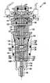
- FIG. 2shows an oil activated fuel injector of the present invention
- FIG. 3Ashows a control valve body of the oil activated fuel injector of the present invention with a spool in a closed position
- FIG. 3Bshows the control valve body of the present invention with the spool in the open position
- FIG. 4Ashows a second embodiment of the control valve body of the present invention with the spool in the closed position
- FIG. 4Bshows the second embodiment of the control valve body of the present invention with the spool in the open position
- FIG. 5shows a third embodiment of the control valve body of the present invention.
- FIGS. 6-10show performance charts of the oil activated fuel injector of the present invention.
- the present inventionis directed to an oil activated electronically, mechanically or hydraulically controlled fuel injector which is capable of substantially decreasing and/or preventing captured air from mixing with the working fluid such as, for example, hydraulic oil, during the fuel injection process.
- the oil activated fuel injector of the present inventionwill also avoid capturing of air in the control valve body as well as grooves or orifices positioned in either a spool or the control valve body, itself.
- the present inventionis also capable of decreasing shot to shot variations in fuel injection at low fuel quantities thus increasing the predictability of the fuel injector throughout a range of hydraulic oil pressures. This increased predictability also leads to increased fuel efficiency even at lower fuel quantities.
- the fuel injectoris generally depicted as reference numeral 100 and includes a control valve body 102 as well as an intensifier body 120 and a nozzle 140 .
- the control valve body 102includes an inlet area 104 which is in fluid communication with working ports 106 .
- At least one groove or orifice (hereinafter referred to as grooves) 108are positioned between and in fluid communication with the inlet area 104 and the working ports 106 .
- At least one of vent hole 110(and preferably two ore more) is located in the control body 102 which are in fluid communication with the working ports 106 .
- the vent holes 110are arranged or designed to eliminate or substantially reduce captured air in the working fluid within the working ports 106 .
- a spool 112 having at least one groove or orifice (hereinafter referred to as grooves) 114is slidably mounted within the control valve body 102 .
- An open coil 116 and a closed coil 118are positioned on opposing sides of the spool 112 and are energized via a driver (not shown) to drive the spool 112 between a closed position and an open position.
- the grooves 114 of the spool 112are aligned with the grooves 108 of the valve control body 102 thus allowing the working fluid to flow between the inlet area 104 and the working ports 106 of the valve control body 102 .
- the intensifier body 120is mounted to the valve control body 102 via any conventional mounting mechanism.
- a seal 122e.g., o-ring
- a piston 124is slidably positioned within the intensifier body 120 (e.g. intensifier chamber) and is in contact with an upper end of a plunger 126 .
- An intensifier spring 128surrounds a portion (e.g., shaft) of the plunger 126 and is further positioned between the piston 124 and a flange or shoulder 129 formed on an interior portion of the intensifier body 120 .
- the intensifier spring 128urges the piston 122 and the plunger 126 in a first position proximate to the valve control body 102 .
- a plurality of venting and pressure release holes 130 and 132are formed in the body of the intensifier body 120 .
- the plurality of venting and pressure release holes 130 and 132are further positioned adjacent the plunger 126 .
- a check disk 134is positioned below the intensifier body 120 remote from the valve control body 102 .
- the combination of an upper surface 134 a of the check disk 134 , an end portion 126 a of the plunger 126 and an interior wall 120 a of the intensifier body 120forms a high pressure chamber 136 .
- a fuel inlet check valve 138is positioned within the check disk 134 and provides fluid communication between the high pressure chamber 136 and a fuel area (not shown). This fluid communication allows fuel to flow into the high pressure chamber 136 from the fuel area during an up-stroke of the plunger 126 .
- the pressure release hole 132is also in fluid communication with the high pressure chamber 136 when the plunger 126 is urged into the first position; however, fluid communication is interrupted when the plunger 126 is urged downwards towards the check disk 134 .
- the check disk 134also includes an angled fuel bore 139 in fluid communication with the high pressure chamber 136 .
- FIG. 2further shows the nozzle 140 and a spring cage 142 .
- the spring cage 142is positioned between the nozzle 140 and the check disk 134 , and includes a straight fuel bore 144 in fluid communication with the angled fuel bore 139 of the check disk 134 .
- the spring cage 142also includes a centrally located bore 148 having a first bore diameter 148 a and a second smaller bore diameter 148 b.
- a spring 150 and a spring seat 152are positioned within the first bore diameter 148 a of the spring cage 142 , and a pin 154 is positioned within the second smaller bore diameter 148 b.
- the nozzle 140includes a second angled bore 146 in alignment with the straight bore 139 of the spring cage 142 .
- a needle 150is preferably centrally located with the nozzle 140 and is urged downwards by the spring 150 (via the pin 154 ).
- a fuel chamber 152surrounds the needle 150 and is in fluid communication with the angled bore 146 .
- a nut 160is threaded about the intensifier body 120 , the check disk 134 , the nozzle 140 and the spring cage 142 .
- FIG. 3Ashows the control valve body 102 of FIG. 2 with the spool 112 in the closed or start position.
- the lower vent holes 110 aare plugged or capped to ensure that air 162 remains above the working fluid level 164 during the venting process.
- the lower vent holes 110 amay be entirely eliminated from the valve control body 102 .
- the working fluid 164rises to a level of the upper vent holes 110 b during the venting process.
- the working fluid 164also fills the grooves 114 of the spool 112 ; however, air 162 may remain in the upper portion of the grooves 108 and the upper vent holes 110 b of the valve control body 102 .
- the air in the upper vent holes 110 b and upper portion of the grooves 108is above the level of the working fluid 164 .
- the working fluid 164 within the inlet area 104will not flow to the working ports 106 due to the non-alignment of the grooves 108 and 114 .
- FIG. 3Bshows the control body 102 with the spool 112 in an open position.
- the grooves 108 of the valve control body 102 and the grooves 114 of the spool 112are in alignment with one another thus allowing the working fluid 164 to flow from the inlet area 104 to the working ports 106 .
- FIG. 3Bshows that during the flow of working fluid 164 only a small amount of air is captured and locked in the grooves 108 . Accordingly, only a small amount of air 162 is then captured in the working fluid 164 . This is because the air 162 remains above the working fluid level 164 when the spool 112 is in the closed position (FIG. 3 A). Thus, only a small amount of captured air will have to be compressed and dissolved by the working fluid thus greatly minimizing shot to shot fuel variations especially for low fuel quantities.
- FIG. 4Ashows a second embodiment of the control valve body 102 with the spool 112 in the closed position.
- the vent holes 110include an inlet 111 which is positioned above the grooves 108 of the valve control body 102 and the grooves 114 of the spool 112 .
- the position of the inlet 111 of the vent holes 110will not permit air to fill the grooves 108 and 114 . This is because the position of the vent holes 110 is positioned such that the working fluid 164 will remain in the vent holes 110 during and after the venting process, and air 162 will thus be prevented from entering the grooves 108 and 114 . That is, the air 164 will always remains above the grooves 108 and 114 .
- FIG. 5shows an embodiment of the control valve body 102 of FIGS. 4A and 4B.
- the vent holes 110include a check valve 166 .
- the check valve 166includes a spring 168 which biases a ball, plate or cone 170 against a seat 172 .
- the vent holesmay face downward due to the use of the check valve 166 .
- the working fluid 164overcomes a spring force of the spring 168 and thus disengages the ball 170 from the seat 172 . This allows the working fluid 164 to vent from the vent holes 110 during the venting process.
- the ball 170will be biased against the seat 172 and will prevent air from entering the system.
- FIG. 6shows a chart depicting several tests of a conventional fuel injector (of known design) and the oil activated fuel injector of FIGS. 2-3B at several different testing pressures.
- the lines 200depict the results relating to the oil activated fuel injector of the present invention and lines 300 depict the results of the conventional fuel injector.
- FIG. 6clearly shows that the performance of the oil activated fuel injector of the present invention is superior to that of a conventional fuel injector (i.e., a fuel injector which does not prevent air from mixing with the working fluid) throughout a range of testing pressures.
- the superior performance of the oil activated fuel injector of the present inventionis shown to be even greater at higher operating pressures such as, for example, 160 bars.
- This superior performanceis attributed to the fact that the oil activated fuel injector of the present invention substantially prevents and, in embodiments, completely eliminates the mixing of air with the working fluid. This is a direct result of the placement and/or design of the vent holes 110 of the control valve body 102 .
- FIGS. 7-10also show the superior performance of the oil activated fuel injector of the present invention compared to a conventional fuel injector.
- FIGS. 7-10use the same test parameters of FIG. 6 .
- a driver(not shown) will first energize the open coil 116 .
- the energized open coil 116will then shift the spool 112 from a start position to an open position.
- the grooves 108 of the control valve body 102will become aligned with the grooves 114 on the spool 112 .
- the alignment of the grooves 108 and 114will allow the pressurized working fluid to flow from the inlet area 104 to the working ports 106 of the control valve body 102 .
- the placement and/or design of the vent holes 110 of the control valve body 102will eliminate the mixing of air with the working fluid.
- the pressurized working fluidbegins to act on the piston 124 and the plunger 126 . That is, the pressurized working fluid will begin to push the piston 124 and the plunger 126 downwards thus compressing the intensifier spring 128 .
- the piston 124is pushed downward, fuel in the high pressure chamber will begin to be compressed via the end portion 126 a of the plunger. The compressed fuel will be forced through the bores 139 , 144 and 146 and into the chamber 158 which surrounds the needle 156 .
- the fuel inlet check valve 138prevents fuel from flowing into the high pressure chamber 136 from the fuel area.
- the fuel pressurewill rise above a needle check valve opening pressure until the needle spring 148 is urged upwards.
- the injection holesare open in the nozzle 140 thus allowing fuel to be injected into the combustion chamber of the engine.
- the driverwill energize the closed coil 118 .
- the magnetic force generated in the closed coil 118will then shift the spool 112 into the closed or start position which, in turn, will close the working ports 106 of the control valve body 102 . That is, the grooves 108 and 114 will no longer be in alignment thus interrupting the flow of working fluid from the inlet area 104 to the working ports 106 .
- the needle spring 150will urge the needle 156 downward towards the injection holes of the nozzle 140 thereby closing the injection holes.
- the intensifier spring 128urges the plunger 126 and the piston 124 into the closed or first position adjacent to the valve control body 102 .
- the pressure release hole 132will release pressure in the high pressure chamber 136 thus allowing fuel to flow into the high pressure chamber 136 (via the fuel inlet check valve 138 ). Now, in the next cycle the fuel can be compressed in the high pressure chamber 136 .
- vent holes 110are arranged or designed to eliminate or substantially reduce captured air in the working fluid within the working ports 106 .
- the lower vent holes 110 aare plugged or capped to ensure that air remains above the working fluid level during the venting process.
- the lower vent holes 110 amay be entirely eliminated from the valve control body 102 .
- the working fluidrises to a level of the upper vent holes 110 b during the venting process.
- the working fluidalso fills the grooves 114 . Any air in the system such as, for example, in the upper vent holes 110 b and an upper portion of the grooves 108 is above the level of the working fluid.
- the spool 112is opened, only a small amount of air is locked in the grooves 108 and is captured in the working fluid. This is because the air remains above the working fluid level when the spool 112 is in the closed position. Thus, only a small amount of captured air will have to be compressed and dissolved by the working fluid thus greatly minimizing shot to shot fuel variation.
- the inlet 111 of the vent holes 110are positioned above the grooves 108 of the valve control body 102 and the grooves 114 of the spool 112 . This position will not permit air to fill the grooves 108 and 114 during the venting process since any air in the vent holes will now always remain above the grooves 108 and 114 .
- the spool 112when the spool 112 is again opened the working fluid will flow between the inlet area 104 and the working ports 106 of the valve control body 102 without any captured air therein.
- the vent holes 110include a check valve 166 which prevents air from entering the system during the venting process.
- a check valve 166which prevents air from entering the system during the venting process.
Landscapes
- Engineering & Computer Science (AREA)
- Chemical & Material Sciences (AREA)
- Combustion & Propulsion (AREA)
- Mechanical Engineering (AREA)
- General Engineering & Computer Science (AREA)
- Physics & Mathematics (AREA)
- Electromagnetism (AREA)
- Fuel-Injection Apparatus (AREA)
Abstract
Description
Claims (27)
Priority Applications (3)
| Application Number | Priority Date | Filing Date | Title |
|---|---|---|---|
| US09/828,169US6631853B2 (en) | 2001-04-09 | 2001-04-09 | Oil activated fuel injector control valve |
| EP02006871AEP1249598A3 (en) | 2001-04-09 | 2002-03-26 | Oil activated fuel injector control valve |
| JP2002106122AJP2002327662A (en) | 2001-04-09 | 2002-04-09 | Valve controller and hydraulically actuated fuel injector equipped with valve controller |
Applications Claiming Priority (1)
| Application Number | Priority Date | Filing Date | Title |
|---|---|---|---|
| US09/828,169US6631853B2 (en) | 2001-04-09 | 2001-04-09 | Oil activated fuel injector control valve |
Publications (2)
| Publication Number | Publication Date |
|---|---|
| US20020145056A1 US20020145056A1 (en) | 2002-10-10 |
| US6631853B2true US6631853B2 (en) | 2003-10-14 |
Family
ID=25251072
Family Applications (1)
| Application Number | Title | Priority Date | Filing Date |
|---|---|---|---|
| US09/828,169Expired - LifetimeUS6631853B2 (en) | 2001-04-09 | 2001-04-09 | Oil activated fuel injector control valve |
Country Status (3)
| Country | Link |
|---|---|
| US (1) | US6631853B2 (en) |
| EP (1) | EP1249598A3 (en) |
| JP (1) | JP2002327662A (en) |
Cited By (8)
| Publication number | Priority date | Publication date | Assignee | Title |
|---|---|---|---|---|
| US20040011900A1 (en)* | 2002-05-22 | 2004-01-22 | Jens Gebhardt | Fuel injector assembly |
| US20040046056A1 (en)* | 2002-08-30 | 2004-03-11 | Dongming Tan | Plunger cavity pressure control for a hydraulically-actuated fuel injector |
| US20040046043A1 (en)* | 2002-09-03 | 2004-03-11 | Martin Luedicke | Solenoid end cap assembly with flat surface |
| US20040123840A1 (en)* | 2001-12-07 | 2004-07-01 | Katja Matz | Fuel injection system for an internal combustion engine |
| US20040163626A1 (en)* | 2003-02-20 | 2004-08-26 | Stockner Alan R. | End of injection rate shaping |
| US20100219266A1 (en)* | 2002-05-22 | 2010-09-02 | Navistar, Inc. | Fuel injector assembly |
| RU2631380C2 (en)* | 2015-03-20 | 2017-09-21 | МАН Дизель унд Турбо, филиал аф МАН Дизель унд Турбо СЕ, Тюскланд | Propellant valve for wet fuel having a low ignition temperature injection into compression chamber of two cycle internal combustion engine with boost-pressure charge and autoignition and two cycle internal combustion engine with boost-pressure charge and autoignition comprising noted valve |
| US11174732B1 (en)* | 2020-05-12 | 2021-11-16 | Pratt & Whitney Canada Corp. | Rotary engine lubrication system using intensifier injector |
Families Citing this family (6)
| Publication number | Priority date | Publication date | Assignee | Title |
|---|---|---|---|---|
| DE102004053422A1 (en)* | 2004-11-05 | 2006-05-11 | Robert Bosch Gmbh | Fuel injection system |
| US9500170B2 (en) | 2012-10-25 | 2016-11-22 | Picospray, Llc | Fuel injection system |
| EP3455498B1 (en) | 2016-05-12 | 2024-07-03 | Briggs & Stratton, LLC | Fuel delivery injector |
| US10947940B2 (en) | 2017-03-28 | 2021-03-16 | Briggs & Stratton, Llc | Fuel delivery system |
| WO2020077181A1 (en) | 2018-10-12 | 2020-04-16 | Briggs & Stratton Corporation | Electronic fuel injection module |
| CN109372658B (en)* | 2018-12-10 | 2020-10-13 | 大连理工大学 | Gas injector of gas engine and working method thereof |
Citations (14)
| Publication number | Priority date | Publication date | Assignee | Title |
|---|---|---|---|---|
| US4182492A (en) | 1978-01-16 | 1980-01-08 | Combustion Research & Technology, Inc. | Hydraulically operated pressure amplification system for fuel injectors |
| US4406307A (en)* | 1981-03-31 | 1983-09-27 | Double A Products Company | Directional valve with spool transfer loop |
| US5359976A (en) | 1992-10-15 | 1994-11-01 | Nippondenso Co., Ltd. | Fuel supply system for internal combustion engines |
| US5454359A (en) | 1994-12-01 | 1995-10-03 | Navistar International Transportation Corp. | Continuous high pressure rail deaeration system for fuel injection system |
| US5460329A (en)* | 1994-06-06 | 1995-10-24 | Sturman; Oded E. | High speed fuel injector |
| US5479901A (en) | 1994-06-27 | 1996-01-02 | Caterpillar Inc. | Electro-hydraulic spool control valve assembly adapted for a fuel injector |
| US5640987A (en)* | 1994-04-05 | 1997-06-24 | Sturman; Oded E. | Digital two, three, and four way solenoid control valves |
| US5878720A (en) | 1997-02-26 | 1999-03-09 | Caterpillar Inc. | Hydraulically actuated fuel injector with proportional control |
| US5964406A (en) | 1998-05-28 | 1999-10-12 | Caterpillar Inc. | Valve area scheduling in a double acting piston for a hydraulically-actuated fuel injector |
| US6053421A (en) | 1998-05-19 | 2000-04-25 | Caterpillar Inc. | Hydraulically-actuated fuel injector with rate shaping spool control valve |
| US6085991A (en)* | 1998-05-14 | 2000-07-11 | Sturman; Oded E. | Intensified fuel injector having a lateral drain passage |
| US6105616A (en) | 1997-03-28 | 2000-08-22 | Sturman Industries, Inc. | Double actuator control valve that has a neutral position |
| US6119960A (en) | 1998-05-07 | 2000-09-19 | Caterpillar Inc. | Solenoid actuated valve and fuel injector using same |
| US6371382B1 (en)* | 1999-02-23 | 2002-04-16 | Hydraulik-Ring Gmbh | Method for machining control edges of a valve for a fuel injection device of an internal combustion engine and fuel injection device with such a valve |
Family Cites Families (3)
| Publication number | Priority date | Publication date | Assignee | Title |
|---|---|---|---|---|
| CA1312018C (en)* | 1987-03-30 | 1992-12-29 | John F. Church | Fuel filter assembly with heater |
| WO1993008400A1 (en)* | 1991-10-21 | 1993-04-29 | Caterpillar Inc. | Engine combustion system |
| JP2002544437A (en)* | 1999-05-18 | 2002-12-24 | インターナショナル エンジン インテレクチュアル プロパティー カンパニー リミテッド ライアビリティ カンパニー | Two-acting two-stage hydraulic pressure control device |
- 2001
- 2001-04-09USUS09/828,169patent/US6631853B2/ennot_activeExpired - Lifetime
- 2002
- 2002-03-26EPEP02006871Apatent/EP1249598A3/ennot_activeWithdrawn
- 2002-04-09JPJP2002106122Apatent/JP2002327662A/enactivePending
Patent Citations (14)
| Publication number | Priority date | Publication date | Assignee | Title |
|---|---|---|---|---|
| US4182492A (en) | 1978-01-16 | 1980-01-08 | Combustion Research & Technology, Inc. | Hydraulically operated pressure amplification system for fuel injectors |
| US4406307A (en)* | 1981-03-31 | 1983-09-27 | Double A Products Company | Directional valve with spool transfer loop |
| US5359976A (en) | 1992-10-15 | 1994-11-01 | Nippondenso Co., Ltd. | Fuel supply system for internal combustion engines |
| US5640987A (en)* | 1994-04-05 | 1997-06-24 | Sturman; Oded E. | Digital two, three, and four way solenoid control valves |
| US5460329A (en)* | 1994-06-06 | 1995-10-24 | Sturman; Oded E. | High speed fuel injector |
| US5479901A (en) | 1994-06-27 | 1996-01-02 | Caterpillar Inc. | Electro-hydraulic spool control valve assembly adapted for a fuel injector |
| US5454359A (en) | 1994-12-01 | 1995-10-03 | Navistar International Transportation Corp. | Continuous high pressure rail deaeration system for fuel injection system |
| US5878720A (en) | 1997-02-26 | 1999-03-09 | Caterpillar Inc. | Hydraulically actuated fuel injector with proportional control |
| US6105616A (en) | 1997-03-28 | 2000-08-22 | Sturman Industries, Inc. | Double actuator control valve that has a neutral position |
| US6119960A (en) | 1998-05-07 | 2000-09-19 | Caterpillar Inc. | Solenoid actuated valve and fuel injector using same |
| US6085991A (en)* | 1998-05-14 | 2000-07-11 | Sturman; Oded E. | Intensified fuel injector having a lateral drain passage |
| US6053421A (en) | 1998-05-19 | 2000-04-25 | Caterpillar Inc. | Hydraulically-actuated fuel injector with rate shaping spool control valve |
| US5964406A (en) | 1998-05-28 | 1999-10-12 | Caterpillar Inc. | Valve area scheduling in a double acting piston for a hydraulically-actuated fuel injector |
| US6371382B1 (en)* | 1999-02-23 | 2002-04-16 | Hydraulik-Ring Gmbh | Method for machining control edges of a valve for a fuel injection device of an internal combustion engine and fuel injection device with such a valve |
Cited By (14)
| Publication number | Priority date | Publication date | Assignee | Title |
|---|---|---|---|---|
| US20040123840A1 (en)* | 2001-12-07 | 2004-07-01 | Katja Matz | Fuel injection system for an internal combustion engine |
| US6976638B2 (en)* | 2001-12-07 | 2005-12-20 | Robert Bosch Gmbh | Fuel injection system for an internal combustion engine |
| US20100219266A1 (en)* | 2002-05-22 | 2010-09-02 | Navistar, Inc. | Fuel injector assembly |
| US20040011900A1 (en)* | 2002-05-22 | 2004-01-22 | Jens Gebhardt | Fuel injector assembly |
| US8382006B2 (en) | 2002-05-22 | 2013-02-26 | Jens Gebhardt | Fuel injector assembly |
| US20040046056A1 (en)* | 2002-08-30 | 2004-03-11 | Dongming Tan | Plunger cavity pressure control for a hydraulically-actuated fuel injector |
| US7007860B2 (en)* | 2002-08-30 | 2006-03-07 | Caterpillar Inc. | Plunger cavity pressure control for a hydraulically-actuated fuel injector |
| US20040046043A1 (en)* | 2002-09-03 | 2004-03-11 | Martin Luedicke | Solenoid end cap assembly with flat surface |
| US7044400B2 (en)* | 2002-09-03 | 2006-05-16 | Siemens Diesel Systems Technology | Solenoid end cap assembly with flat surface |
| US20040163626A1 (en)* | 2003-02-20 | 2004-08-26 | Stockner Alan R. | End of injection rate shaping |
| US7059301B2 (en)* | 2003-02-20 | 2006-06-13 | Caterpillar Inc. | End of injection rate shaping |
| RU2631380C2 (en)* | 2015-03-20 | 2017-09-21 | МАН Дизель унд Турбо, филиал аф МАН Дизель унд Турбо СЕ, Тюскланд | Propellant valve for wet fuel having a low ignition temperature injection into compression chamber of two cycle internal combustion engine with boost-pressure charge and autoignition and two cycle internal combustion engine with boost-pressure charge and autoignition comprising noted valve |
| US11174732B1 (en)* | 2020-05-12 | 2021-11-16 | Pratt & Whitney Canada Corp. | Rotary engine lubrication system using intensifier injector |
| US20210355898A1 (en)* | 2020-05-12 | 2021-11-18 | Pratt & Whitney Canada Corp. | Rotary engine lubrication system using intensifier injector |
Also Published As
| Publication number | Publication date |
|---|---|
| US20020145056A1 (en) | 2002-10-10 |
| EP1249598A2 (en) | 2002-10-16 |
| EP1249598A3 (en) | 2004-09-08 |
| JP2002327662A (en) | 2002-11-15 |
Similar Documents
| Publication | Publication Date | Title |
|---|---|---|
| US6631853B2 (en) | Oil activated fuel injector control valve | |
| KR100941794B1 (en) | Fuel injector with controlled high pressure fuel passage | |
| EP0269289A2 (en) | Diesel unit fuel injector with spill assist injection needle valve closure | |
| US5852997A (en) | Common rail injector | |
| EP0774067B1 (en) | Solenoid actuated miniservo spool valve | |
| JPH07332193A (en) | Fuel injection valve for internal combustion engine | |
| JPH01151768A (en) | Electronic unit injector | |
| US20030155437A1 (en) | Fuel injector with dual control valve | |
| JP4173821B2 (en) | Fuel injection device for internal combustion engine | |
| WO2000055490A1 (en) | Fuel injector | |
| US6715694B2 (en) | Control valve body for an oil activated fuel injector | |
| US6474304B1 (en) | Double-acting two-stage hydraulic control device | |
| US7367517B2 (en) | Fuel injection device inhibiting abrasion | |
| US6003497A (en) | Mechanically actuated hydraulically amplified fuel injector with electrically controlled pressure relief | |
| US6913212B2 (en) | Oil activated fuel injector control with delay plunger | |
| US6908040B2 (en) | Unit injector with stabilized pilot injection | |
| US6749130B2 (en) | Check line valve faster venting method | |
| US6526943B2 (en) | Control valve for hydraulically oil activated fuel injector | |
| US6923382B2 (en) | Hydraulically actuated injector with delay piston and method of using the same | |
| US6908042B2 (en) | Fuel injector | |
| US6591812B2 (en) | Rail connection with rate shaping behavior for a hydraulically actuated fuel injector | |
| WO2006033469A1 (en) | Fuel injection device | |
| US20100108786A1 (en) | Fuel injector assembly | |
| JPH0467021B2 (en) | ||
| US20040124275A1 (en) | Fuel injection system for internal combustion engines |
Legal Events
| Date | Code | Title | Description |
|---|---|---|---|
| AS | Assignment | Owner name:SIEMENS DIESEL SYSTEMS TECHNOLOGIES, LLC, SOUTH CA Free format text:ASSIGNMENT OF ASSIGNORS INTEREST;ASSIGNORS:LENK, MARTIN;NIETHAMMER, BERND;REEL/FRAME:011708/0953;SIGNING DATES FROM 20010309 TO 20010402 | |
| STCF | Information on status: patent grant | Free format text:PATENTED CASE | |
| FPAY | Fee payment | Year of fee payment:4 | |
| FEPP | Fee payment procedure | Free format text:PAYOR NUMBER ASSIGNED (ORIGINAL EVENT CODE: ASPN); ENTITY STATUS OF PATENT OWNER: LARGE ENTITY | |
| FPAY | Fee payment | Year of fee payment:8 | |
| AS | Assignment | Owner name:JPMORGAN CHASE BANK, N.A., AS COLLATERAL AGENT, NE Free format text:SECURITY AGREEMENT;ASSIGNORS:INTERNATIONAL ENGINE INTELLECTUAL PROPERTY COMPANY, LLC;INTERNATIONAL TRUCK INTELLECTUAL PROPERTY COMPANY, LLC;NAVISTAR INTERNATIONAL CORPORATION;AND OTHERS;REEL/FRAME:028944/0730 Effective date:20120817 | |
| FPAY | Fee payment | Year of fee payment:12 | |
| AS | Assignment | Owner name:JPMORGAN CHASE BANK N.A., AS COLLATERAL AGENT, NEW Free format text:SECURITY AGREEMENT;ASSIGNORS:NAVISTAR INTERNATIONAL CORPORATION;INTERNATIONAL TRUCK INTELLECTUAL PROPERTY COMPANY, LLC;INTERNATIONAL ENGINE INTELLECTUAL PROPERTY COMPANY, LLC;REEL/FRAME:036616/0243 Effective date:20150807 | |
| AS | Assignment | Owner name:JPMORGAN CHASE BANK, N.A., AS COLLATERAL AGENT, NEW YORK Free format text:SECURITY INTEREST;ASSIGNORS:NAVISTAR INTERNATIONAL CORPORATION;NAVISTAR, INC.;REEL/FRAME:044418/0310 Effective date:20171106 Owner name:INTERNATIONAL TRUCK INTELLECTUAL PROPERTY COMPANY, Free format text:RELEASE BY SECURED PARTY;ASSIGNOR:JPMORGAN CHASE BANK, N.A., AS COLLATERAL AGENT;REEL/FRAME:044780/0456 Effective date:20171106 Owner name:INTERNATIONAL ENGINE INTELLECTUAL PROPERTY COMPANY Free format text:RELEASE BY SECURED PARTY;ASSIGNOR:JPMORGAN CHASE BANK, N.A., AS COLLATERAL AGENT;REEL/FRAME:044780/0456 Effective date:20171106 Owner name:NAVISTAR INTERNATIONAL CORPORATION, ILLINOIS Free format text:RELEASE BY SECURED PARTY;ASSIGNOR:JPMORGAN CHASE BANK, N.A., AS COLLATERAL AGENT;REEL/FRAME:044780/0456 Effective date:20171106 Owner name:NAVISTAR, INC., ILLINOIS Free format text:RELEASE BY SECURED PARTY;ASSIGNOR:JPMORGAN CHASE BANK, N.A., AS COLLATERAL AGENT;REEL/FRAME:044416/0867 Effective date:20171106 Owner name:JPMORGAN CHASE BANK, N.A., AS COLLATERAL AGENT, NE Free format text:SECURITY INTEREST;ASSIGNORS:NAVISTAR INTERNATIONAL CORPORATION;NAVISTAR, INC.;REEL/FRAME:044418/0310 Effective date:20171106 Owner name:NAVISTAR INTERNATIONAL CORPORATION, ILLINOIS Free format text:RELEASE BY SECURED PARTY;ASSIGNOR:JPMORGAN CHASE BANK, N.A., AS COLLATERAL AGENT;REEL/FRAME:044416/0867 Effective date:20171106 Owner name:INTERNATIONAL ENGINE INTELLECTUAL PROPERTY COMPANY Free format text:RELEASE BY SECURED PARTY;ASSIGNOR:JPMORGAN CHASE BANK, N.A., AS COLLATERAL AGENT;REEL/FRAME:044416/0867 Effective date:20171106 Owner name:INTERNATIONAL TRUCK INTELLECTUAL PROPERTY COMPANY, Free format text:RELEASE BY SECURED PARTY;ASSIGNOR:JPMORGAN CHASE BANK, N.A., AS COLLATERAL AGENT;REEL/FRAME:044416/0867 Effective date:20171106 | |
| AS | Assignment | Owner name:PURE POWER TECHNOLOGIES, INC., SOUTH CAROLINA Free format text:TERMINATION AND RELEASE OF SECURITY INTEREST IN PATENTS;ASSIGNOR:BANK OF AMERICA, N.A.;REEL/FRAME:048826/0493 Effective date:20190408 | |
| AS | Assignment | Owner name:JPMORGAN CHASE BANK, N.A., AS ADMINISTRATIVE AGENT, NEW YORK Free format text:SECURITY INTEREST;ASSIGNORS:INTERNATIONAL TRUCK INTELLECTUAL PROPERTY COMPANY, LLC;INTERNATIONAL ENGINE INTELLECTUAL PROPERTY COMPANY, LLC;NAVISTAR, INC. (F/K/A INTERNATIONAL TRUCK AND ENGINE CORPORATION);REEL/FRAME:052483/0742 Effective date:20200423 | |
| AS | Assignment | Owner name:THE BANK OF NEW YORK MELLON TRUST COMPANY, N.A., AS COLLATERAL AGENT, ILLINOIS Free format text:SECURITY INTEREST;ASSIGNORS:NAVISTAR INTERNATIONAL CORPORATION;INTERNATIONAL ENGINE INTELLECTUAL PROPERTY COMPANY, LLC;INTERNATIONAL TRUCK INTELLECTUAL PROPERTY COMPANY, LLC;AND OTHERS;REEL/FRAME:053545/0443 Effective date:20200427 Owner name:JPMORGAN CHASE BANK, N.A., AS ADMINISTRATIVE AGENT, NEW YORK Free format text:CORRECTIVE ASSIGNMENT TO CORRECT THE CONVEYING PARTY DATA PREVIOUSLY RECORDED AT REEL: 052483 FRAME: 0742. ASSIGNOR(S) HEREBY CONFIRMS THE SECURITY INTEREST.;ASSIGNORS:NAVISTAR INTERNATIONAL CORPORATION;INTERNATIONAL ENGINE INTELLECTUAL PROPERTY COMPANY, LLC;INTERNATIONAL TRUCK INTELLECTUAL PROPERTY COMPANY, LLC;AND OTHERS;REEL/FRAME:053457/0001 Effective date:20200423 | |
| AS | Assignment | Owner name:INTERNATIONAL TRUCK INTELLECTUAL PROPERTY COMPANY, LLC, ILLINOIS Free format text:RELEASE BY SECURED PARTY;ASSIGNOR:JPMORGAN CHASE BANK, N.A., AS ADMINISTRATIVE AGENT;REEL/FRAME:056757/0136 Effective date:20210701 Owner name:NAVISTAR, INC. (F/KA/ INTERNATIONAL TRUCK AND ENGINE CORPORATION), ILLINOIS Free format text:RELEASE BY SECURED PARTY;ASSIGNOR:JPMORGAN CHASE BANK, N.A., AS ADMINISTRATIVE AGENT;REEL/FRAME:056757/0136 Effective date:20210701 Owner name:INTERNATIONAL ENGINE INTELLECTUAL PROPERTY COMPANY, LLC, ILLINOIS Free format text:RELEASE BY SECURED PARTY;ASSIGNOR:JPMORGAN CHASE BANK, N.A., AS ADMINISTRATIVE AGENT;REEL/FRAME:056757/0136 Effective date:20210701 | |
| AS | Assignment | Owner name:NAVISTAR, INC., ILLINOIS Free format text:RELEASE OF SECURITY INTEREST RECORDED AT REEL/FRAME 53545/443;ASSIGNOR:THE BANK OF NEW YORK MELLON TRUST COMPANY, N.A.;REEL/FRAME:057441/0404 Effective date:20210701 Owner name:INTERNATIONAL ENGINE INTELLECTUAL PROPERTY COMPANY, LLC, ILLINOIS Free format text:RELEASE OF SECURITY INTEREST RECORDED AT REEL/FRAME 53545/443;ASSIGNOR:THE BANK OF NEW YORK MELLON TRUST COMPANY, N.A.;REEL/FRAME:057441/0404 Effective date:20210701 Owner name:INTERNATIONAL TRUCK INTELLECTUAL PROPERTY COMPANY, LLC, ILLINOIS Free format text:RELEASE OF SECURITY INTEREST RECORDED AT REEL/FRAME 53545/443;ASSIGNOR:THE BANK OF NEW YORK MELLON TRUST COMPANY, N.A.;REEL/FRAME:057441/0404 Effective date:20210701 Owner name:NAVISTAR INTERNATIONAL CORPORATION, ILLINOIS Free format text:RELEASE OF SECURITY INTEREST RECORDED AT REEL/FRAME 53545/443;ASSIGNOR:THE BANK OF NEW YORK MELLON TRUST COMPANY, N.A.;REEL/FRAME:057441/0404 Effective date:20210701 |