US6631775B1 - Electric vehicle chassis with removable battery module and a method for battery module replacement - Google Patents
Electric vehicle chassis with removable battery module and a method for battery module replacementDownload PDFInfo
- Publication number
- US6631775B1 US6631775B1US09/610,908US61090800AUS6631775B1US 6631775 B1US6631775 B1US 6631775B1US 61090800 AUS61090800 AUS 61090800AUS 6631775 B1US6631775 B1US 6631775B1
- Authority
- US
- United States
- Prior art keywords
- chassis
- battery module
- powered vehicle
- electric powered
- battery
- Prior art date
- Legal status (The legal status is an assumption and is not a legal conclusion. Google has not performed a legal analysis and makes no representation as to the accuracy of the status listed.)
- Expired - Fee Related, expires
Links
- 238000000034methodMethods0.000titleabstractdescription4
- 230000005672electromagnetic fieldEffects0.000claimsdescription10
- 238000010276constructionMethods0.000claimsdescription5
- 238000003780insertionMethods0.000claimsdescription4
- 230000037431insertionEffects0.000claimsdescription4
- 230000000712assemblyEffects0.000description6
- 238000000429assemblyMethods0.000description6
- 238000003466weldingMethods0.000description5
- XUIMIQQOPSSXEZ-UHFFFAOYSA-NSiliconChemical compound[Si]XUIMIQQOPSSXEZ-UHFFFAOYSA-N0.000description1
- 230000005540biological transmissionEffects0.000description1
- QELJHCBNGDEXLD-UHFFFAOYSA-Nnickel zincChemical compound[Ni].[Zn]QELJHCBNGDEXLD-UHFFFAOYSA-N0.000description1
- 229910052710siliconInorganic materials0.000description1
- 239000010703siliconSubstances0.000description1
- 239000000725suspensionSubstances0.000description1
Images


Classifications
- B—PERFORMING OPERATIONS; TRANSPORTING
- B60—VEHICLES IN GENERAL
- B60K—ARRANGEMENT OR MOUNTING OF PROPULSION UNITS OR OF TRANSMISSIONS IN VEHICLES; ARRANGEMENT OR MOUNTING OF PLURAL DIVERSE PRIME-MOVERS IN VEHICLES; AUXILIARY DRIVES FOR VEHICLES; INSTRUMENTATION OR DASHBOARDS FOR VEHICLES; ARRANGEMENTS IN CONNECTION WITH COOLING, AIR INTAKE, GAS EXHAUST OR FUEL SUPPLY OF PROPULSION UNITS IN VEHICLES
- B60K1/00—Arrangement or mounting of electrical propulsion units
- B60K1/04—Arrangement or mounting of electrical propulsion units of the electric storage means for propulsion
- B—PERFORMING OPERATIONS; TRANSPORTING
- B60—VEHICLES IN GENERAL
- B60L—PROPULSION OF ELECTRICALLY-PROPELLED VEHICLES; SUPPLYING ELECTRIC POWER FOR AUXILIARY EQUIPMENT OF ELECTRICALLY-PROPELLED VEHICLES; ELECTRODYNAMIC BRAKE SYSTEMS FOR VEHICLES IN GENERAL; MAGNETIC SUSPENSION OR LEVITATION FOR VEHICLES; MONITORING OPERATING VARIABLES OF ELECTRICALLY-PROPELLED VEHICLES; ELECTRIC SAFETY DEVICES FOR ELECTRICALLY-PROPELLED VEHICLES
- B60L50/00—Electric propulsion with power supplied within the vehicle
- B60L50/50—Electric propulsion with power supplied within the vehicle using propulsion power supplied by batteries or fuel cells
- B60L50/60—Electric propulsion with power supplied within the vehicle using propulsion power supplied by batteries or fuel cells using power supplied by batteries
- B60L50/66—Arrangements of batteries
- B—PERFORMING OPERATIONS; TRANSPORTING
- B60—VEHICLES IN GENERAL
- B60L—PROPULSION OF ELECTRICALLY-PROPELLED VEHICLES; SUPPLYING ELECTRIC POWER FOR AUXILIARY EQUIPMENT OF ELECTRICALLY-PROPELLED VEHICLES; ELECTRODYNAMIC BRAKE SYSTEMS FOR VEHICLES IN GENERAL; MAGNETIC SUSPENSION OR LEVITATION FOR VEHICLES; MONITORING OPERATING VARIABLES OF ELECTRICALLY-PROPELLED VEHICLES; ELECTRIC SAFETY DEVICES FOR ELECTRICALLY-PROPELLED VEHICLES
- B60L53/00—Methods of charging batteries, specially adapted for electric vehicles; Charging stations or on-board charging equipment therefor; Exchange of energy storage elements in electric vehicles
- B60L53/80—Exchanging energy storage elements, e.g. removable batteries
- B—PERFORMING OPERATIONS; TRANSPORTING
- B62—LAND VEHICLES FOR TRAVELLING OTHERWISE THAN ON RAILS
- B62D—MOTOR VEHICLES; TRAILERS
- B62D21/00—Understructures, i.e. chassis frame on which a vehicle body may be mounted
- B62D21/12—Understructures, i.e. chassis frame on which a vehicle body may be mounted assembled from readily detachable parts
- B—PERFORMING OPERATIONS; TRANSPORTING
- B60—VEHICLES IN GENERAL
- B60G—VEHICLE SUSPENSION ARRANGEMENTS
- B60G2206/00—Indexing codes related to the manufacturing of suspensions: constructional features, the materials used, procedures or tools
- B60G2206/01—Constructional features of suspension elements, e.g. arms, dampers, springs
- B60G2206/011—Modular constructions
- B—PERFORMING OPERATIONS; TRANSPORTING
- B60—VEHICLES IN GENERAL
- B60G—VEHICLE SUSPENSION ARRANGEMENTS
- B60G2300/00—Indexing codes relating to the type of vehicle
- B60G2300/50—Electric vehicles; Hybrid vehicles
- B—PERFORMING OPERATIONS; TRANSPORTING
- B60—VEHICLES IN GENERAL
- B60K—ARRANGEMENT OR MOUNTING OF PROPULSION UNITS OR OF TRANSMISSIONS IN VEHICLES; ARRANGEMENT OR MOUNTING OF PLURAL DIVERSE PRIME-MOVERS IN VEHICLES; AUXILIARY DRIVES FOR VEHICLES; INSTRUMENTATION OR DASHBOARDS FOR VEHICLES; ARRANGEMENTS IN CONNECTION WITH COOLING, AIR INTAKE, GAS EXHAUST OR FUEL SUPPLY OF PROPULSION UNITS IN VEHICLES
- B60K1/00—Arrangement or mounting of electrical propulsion units
- B60K1/04—Arrangement or mounting of electrical propulsion units of the electric storage means for propulsion
- B60K2001/0405—Arrangement or mounting of electrical propulsion units of the electric storage means for propulsion characterised by their position
- B60K2001/0438—Arrangement under the floor
- B—PERFORMING OPERATIONS; TRANSPORTING
- B60—VEHICLES IN GENERAL
- B60K—ARRANGEMENT OR MOUNTING OF PROPULSION UNITS OR OF TRANSMISSIONS IN VEHICLES; ARRANGEMENT OR MOUNTING OF PLURAL DIVERSE PRIME-MOVERS IN VEHICLES; AUXILIARY DRIVES FOR VEHICLES; INSTRUMENTATION OR DASHBOARDS FOR VEHICLES; ARRANGEMENTS IN CONNECTION WITH COOLING, AIR INTAKE, GAS EXHAUST OR FUEL SUPPLY OF PROPULSION UNITS IN VEHICLES
- B60K1/00—Arrangement or mounting of electrical propulsion units
- B60K1/04—Arrangement or mounting of electrical propulsion units of the electric storage means for propulsion
- B60K2001/0455—Removal or replacement of the energy storages
- B60K2001/0461—Removal or replacement of the energy storages from the side
- Y—GENERAL TAGGING OF NEW TECHNOLOGICAL DEVELOPMENTS; GENERAL TAGGING OF CROSS-SECTIONAL TECHNOLOGIES SPANNING OVER SEVERAL SECTIONS OF THE IPC; TECHNICAL SUBJECTS COVERED BY FORMER USPC CROSS-REFERENCE ART COLLECTIONS [XRACs] AND DIGESTS
- Y02—TECHNOLOGIES OR APPLICATIONS FOR MITIGATION OR ADAPTATION AGAINST CLIMATE CHANGE
- Y02T—CLIMATE CHANGE MITIGATION TECHNOLOGIES RELATED TO TRANSPORTATION
- Y02T10/00—Road transport of goods or passengers
- Y02T10/60—Other road transportation technologies with climate change mitigation effect
- Y02T10/70—Energy storage systems for electromobility, e.g. batteries
- Y—GENERAL TAGGING OF NEW TECHNOLOGICAL DEVELOPMENTS; GENERAL TAGGING OF CROSS-SECTIONAL TECHNOLOGIES SPANNING OVER SEVERAL SECTIONS OF THE IPC; TECHNICAL SUBJECTS COVERED BY FORMER USPC CROSS-REFERENCE ART COLLECTIONS [XRACs] AND DIGESTS
- Y02—TECHNOLOGIES OR APPLICATIONS FOR MITIGATION OR ADAPTATION AGAINST CLIMATE CHANGE
- Y02T—CLIMATE CHANGE MITIGATION TECHNOLOGIES RELATED TO TRANSPORTATION
- Y02T10/00—Road transport of goods or passengers
- Y02T10/60—Other road transportation technologies with climate change mitigation effect
- Y02T10/7072—Electromobility specific charging systems or methods for batteries, ultracapacitors, supercapacitors or double-layer capacitors
- Y—GENERAL TAGGING OF NEW TECHNOLOGICAL DEVELOPMENTS; GENERAL TAGGING OF CROSS-SECTIONAL TECHNOLOGIES SPANNING OVER SEVERAL SECTIONS OF THE IPC; TECHNICAL SUBJECTS COVERED BY FORMER USPC CROSS-REFERENCE ART COLLECTIONS [XRACs] AND DIGESTS
- Y02—TECHNOLOGIES OR APPLICATIONS FOR MITIGATION OR ADAPTATION AGAINST CLIMATE CHANGE
- Y02T—CLIMATE CHANGE MITIGATION TECHNOLOGIES RELATED TO TRANSPORTATION
- Y02T90/00—Enabling technologies or technologies with a potential or indirect contribution to GHG emissions mitigation
- Y02T90/10—Technologies relating to charging of electric vehicles
- Y02T90/12—Electric charging stations
- Y—GENERAL TAGGING OF NEW TECHNOLOGICAL DEVELOPMENTS; GENERAL TAGGING OF CROSS-SECTIONAL TECHNOLOGIES SPANNING OVER SEVERAL SECTIONS OF THE IPC; TECHNICAL SUBJECTS COVERED BY FORMER USPC CROSS-REFERENCE ART COLLECTIONS [XRACs] AND DIGESTS
- Y02—TECHNOLOGIES OR APPLICATIONS FOR MITIGATION OR ADAPTATION AGAINST CLIMATE CHANGE
- Y02T—CLIMATE CHANGE MITIGATION TECHNOLOGIES RELATED TO TRANSPORTATION
- Y02T90/00—Enabling technologies or technologies with a potential or indirect contribution to GHG emissions mitigation
- Y02T90/10—Technologies relating to charging of electric vehicles
- Y02T90/14—Plug-in electric vehicles
Definitions
- the present inventionrelates to electric powered vehicles, and more particularly, but not by way of limitation, to an electric vehicle chassis having a removable battery module and a business method of replacing the battery module.
- An electrical powered vehicletypically includes an electric motor and drive train supported on a frame and enclosed in a body.
- a battery or bank of batteriesare supported on the frame and connect to the electric motor to provide power thereto.
- the battery or bank of batteriesrequires a separate compartment and mounting assembly, which greatly increases vehicle weight and, thus, significantly limits vehicle range.
- the battery or bank of batterieswas not normally removable from the vehicle, which rendered the vehicle inoperative during charging.
- an electric powered vehiclein accordance with the present invention, includes a chassis defining a battery module compartment and a battery module insertable into the battery module compartment of the chassis.
- the electric powered vehiclefurther includes an access door coupled to the chassis, wherein the access door pivots from a closed position over the battery module compartment to an open position exposing the battery module compartment.
- the battery moduleincludes a battery tray having an ignition contact to provide an electrical connection between the battery tray and an ignition system of the electric powered vehicle and a battery insertable into the battery tray.
- the batteryincludes an ignition contact to provide an electrical connection between the battery and the battery tray.
- the electric powered vehiclefurther includes a locking assembly for locking the battery module within the battery module compartment of the chassis.
- the locking assemblyincludes a bolt residing within a cavity in the chassis, a biasing member for biasing the bolt to an unlocked position, and an electromagnetic field generator for generating an electromagnetic field that draws the bolt to a locked position within a cavity in the battery module.
- the locking assemblyfurther includes a power contact engaged by the bolt in its locked position to provide an electrical connection among a battery of the battery module, the bolt, and an electric motor of the electric powered vehicle.
- the locking assemblystill further includes an ignition contact engaged by the electromagnetic field generator to provide an electrical connection among a battery of the battery module, the electromagnetic field generator, and an ignition system of the electric powered vehicle.
- the chassisincludes a chassis front having a cross-member defining a front portion of the battery module compartment and a chassis rear having a cross-member defining a rear portion of the battery module compartment.
- the chassis front, the chassis rear, and a body of the electric vehiclemay be formed integrally in a unibody construction, wherein a section of the body spanning the chassis front and the chassis rear defines a side portion of the battery module compartment.
- a chassis contactmay be attached to the section of the body spanning the chassis front and the chassis rear to provide an electrical connection between a battery of the battery module and an ignition system of the electric powered vehicle.
- the chassis contactmay be attached to the chassis front to provide an electrical connection between a battery of the battery module and an ignition system of the electric powered vehicle.
- the chassismay further include a support member attached between the chassis front and the chassis rear, wherein the support member defines a side portion of the battery module compartment.
- the chassis contactmay be attached to the support member to provide an electrical connection between a battery of the battery module and an ignition system of the electric powered vehicle.
- a method of replacing a battery module of an electric powered vehicleprovides a service facility including a plurality of battery modules and a system for charging the battery modules.
- the depleted battery moduleis removed from the electric powered vehicle and replaced with a battery module including a fully charged battery.
- the driveris then charged for the battery module including the fully charged battery, and the depleted battery module is recharged.
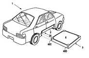
- FIG. 1is a side view illustrating an electric vehicle including an access door to a battery module compartment.
- FIG. 2is a perspective view illustrating the electric vehicle with a battery module removed.
- FIG. 3is a perspective view illustrating a chassis of the electric vehicle including the battery module inserted therein.
- FIG. 4is an exploded perspective view illustrating the chassis and the battery module.
- FIG. 5is a cutout section view of the chassis illustrating a locking assembly.
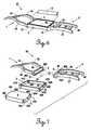
- FIG. 6is a perspective view illustrating an alternative chassis of the electric vehicle including the battery module inserted therein.
- FIG. 7is an exploded perspective view illustrating the alternative chassis and the battery module.
- FIG. 8is a section view illustrating a power supply system of the electric vehicle.
- an electric vehicle 1includes a chassis 5 defining a battery module compartment 25 for receiving a battery module 3 therein.
- the electric vehicle 1further includes an access door 2 attached to the chassis 5 to provide access to the battery module compartment 25 .
- the electric vehicle 1includes components well known to those of ordinary skill in the art, such as, an electric motor 18 , a drive train including a transmission, wheels, a body, a suspension system, a braking system, a steering system, seats, interior amenities, and the like. These components mount to the chassis 5 and connect together in a manner well known to those of ordinary skill in the art to form the electric vehicle 1 .
- the chassis 5includes a chassis front 6 , a chassis rear 7 , and a support member 8 .
- the chassis front 6includes forks 26 and 27 spaced apart an appropriate distance and connected by crossbars 28 and 29 using any suitable means, such as welding.
- the crossbars 28 and 29are spaced at appropriate intervals along the forks 26 and 27 to provide stability and support.
- a cross-member 30attaches between the forks 26 and 27 at an interior end, using any suitable means, such as welding.
- the cross-member 30defines a front portion of the battery module compartment 25 and includes a support ledge 31 for receiving and supporting the battery module 3 thereon.
- the forks 26 and 27include a cylindrical cavity 32 A and 32 B, respectively, at an interior end, which forms part of a locking assembly 12 (described herein with reference to FIG. 5 ).
- the chassis rear 7includes forks 33 and 34 spaced apart an appropriate distance and connected by a crossbar 35 using any suitable means, such as welding, to provide stability and support.
- a cross-member 36attaches between the forks 33 and 34 at an interior end, using any suitable means, such as welding.
- the cross-member 36defines a rear portion of the battery module compartment 25 and includes a support ledge 37 for receiving and supporting the battery module 3 thereon.
- the forks 33 and 34include a cylindrical cavity 38 C and 38 D, respectively, at an interior end, which forms part of the locking assembly 12 (described herein with reference to FIG. 5 ). at an interior end, which forms part of the locking assembly 12 (described herein with reference to FIG. 5 ).
- the support member 8attaches at an interior side end of the chassis front 6 and the chassis rear 7 using any suitable means, such as welding, to couple the chassis front 6 and chassis rear 7 together, thereby providing stability and support.
- the support member 8further defines a side portion of the battery module compartment 25 to facilitate proper positioning of the battery module 3 within the battery module compartment 25 .
- a chassis contact 9attaches at an interior face of the support member 8 to aid in the delivery of power to the locking assembly 12 (described herein with reference to FIG. 8 ).
- the access door 2pivotally connects at an interior side end of the chassis front 6 and the chassis rear 7 opposite to the support member 8 using any suitable means, such as pins inserted within a cavity.
- the access door 2is movable from a closed position to an open position. In the closed position, the access door 2 seals the battery module compartment 25 to lock the battery module 3 within the chassis 5 , thereby preventing dislodgment or unwanted removal of the battery module 3 from the chassis 5 . In the open position, the access door 2 exposes the battery module compartment 25 to permit access to the battery module 3 for replacement. It should be understood that, in the closed position, the access door 2 would be maintained shut using any suitable latching mechanism.
- the access door 2may include a suitable locking mechanism operable only by a vehicle owner or authorized service technician to prevent the theft of the battery module 3 .
- the access door 2opens upwards and attaches to the chassis 5 , those of ordinary skill in the art will recognize that the access door 2 may open downwards as well as connect to the electric vehicle 1 at other suitable locations, such as the body.
- the battery module 3includes a battery 4 and a battery tray 39 defining an enclosure for receiving the battery 4 therein.
- the battery tray 39includes cylindrical cavities 40 A-D at each end, which form part of a locking assembly 12 (described herein with reference to FIG. 5 ).
- the battery tray 39further includes ignition contacts 10 and 41 A-D, which aid in the delivery of power to the locking assembly 12 (described herein with reference to FIG. 8 ).
- the battery tray 39still further includes power contacts 42 A and B at a front end, which aid in the delivery of power to the electric motor 18 (described herein with reference to FIG. 8 ).
- the battery 4 in this preferred embodimentis a rechargeable battery, such as a nickelzinc battery, well known to those of ordinary skill in the art.
- the battery 4fits within the battery tray 39 and is held therein either through a friction fit or a suitable securing mechanism, such as a clamp, strap, or the like.
- the battery 4includes ignition contacts 11 and 16 A-D, which engage the ignition contacts 10 and 41 A-D of the battery tray 39 to permit the delivery of power from the battery 4 to the locking assembly 12 (described herein with reference to FIG. 8 ).
- the battery 4further includes power contacts 14 A and B at a front end, which engage the power contacts 42 A and B of the battery tray 39 to aid in the delivery of power from the battery 4 to the electric motor 18 (described herein with reference to FIG. 8 ).
- a locking assembly 12includes a bolt 13 and a natural magnet 17 , which reside in the cylindrical cavity 32 A.
- the locking assembly 12further includes a coil 15 , an ignition contact 41 A connected to the coil 15 , and a power contact 42 A engaged with the cylindrical cavity 40 A.
- a locking assembly 12 associated with cylindrical cavities 32 A and 40 Awill be described because the locking assembly 12 associated with the cylindrical cavities 32 B and 40 B is identical.
- the locking assemblies 12 associated with the cylindrical cavities 38 C and 40 C and with the cylindrical cavities 38 D and 40 Dare identical, except those locking assemblies do not include a power contact as they merely lock the battery module to the rear chassis 7 and do not aid in the delivery of power from the battery 4 to the electric motor 18 .
- the natural magnet 17attaches at the rear of the cylindrical cavity 32 A using any suitable means, and the coil 15 resides within the battery tray 39 in a position encircling the cylindrical cavity 40 A.
- the bolt 13slides freely within the cylindrical cavity 32 A from an unlocked to a locked position.
- the natural magnet 17draws the bolt 13 away from the cylindrical cavity 40 A and completely into the cylindrical cavity 32 A, which is the unlocked position.
- the battery module 3may be removed from the chassis 5 , as the bolt 13 does not engage the battery tray 39 .
- a natural magnet 17is disclosed, those of ordinary skill in the art will recognize other suitable means for maintaining the bolt 13 in the unlocked position, such as a spring.
- the coil 15When power is applied to the locking assembly 12 , the coil 15 energizes, creating an electromagnetic field that overcomes the magnetic field of the natural magnet 17 , thereby drawing the bolt 13 into the cylindrical cavity 40 A of the battery tray 39 .
- the coil 15draws the bolt 13 into the cylindrical cavity 40 A until the bolt 13 engages the power contact 42 A, which is the locked position.
- the battery module 3In the locked position, the battery module 3 cannot be removed from the chassis 5 , as the bolt 13 engages the battery tray 39 .
- the boltserves as a contact in the transfer of power from the battery 4 to the electric motor 18 (described herein with reference to FIG. 8 ).
- the preferred embodimentdiscloses four locking assemblies, those of ordinary skill in the art will recognize that only one is necessary to maintain the battery module 3 within the chassis 5 and to aid in the delivery of power from the battery 4 to the electric motor 18 .
- a fully charged battery 4is placed within a battery tray 39 to form a battery module 3 .
- the ignition contacts 11 and 16 A-D of the battery 4engage the ignition contacts 10 and 41 A-D of the battery tray 39
- the power contacts 14 A and B of the battery 4engage the power contacts 42 A and B of the battery tray 39 .
- the access door 2is moved to its open position to expose the battery module compartment 25 and permit the removal of a depleted battery module 3 .
- the locking assembly 12is in its unlocked position due to the absence of power.
- the battery module 3is positioned on the support ledges 3 land 37 of the cross-members 30 and 36 and slid into the battery module compartment 25 until the battery module 3 contacts and resides against the support member 8 .
- the cylindrical cavities 32 A and B and 38 C and Dalign with a respective cylindrical cavity 40 A-D.
- the ignition contact 10resides completely through the battery tray 39 such that the ignition contact 10 engages the chassis contact 9 to form an electrical connection therebetween.
- the access door 2is moved to its closed position to seal the battery module compartment 25 , thereby preventing removal of the battery module 3 .
- the locking assembly 12moves to its locked position to secure the battery module 3 within the battery module compartment 25 .
- the chassis 5defines a battery module compartment 25 that receives a battery module 3 therein, which becomes part of the chassis 5 , to solve the excessive weight problem associated with electrical powered vehicles.
- the chassis 5includes a removed portion (i.e., the battery module compartment 25 ) so that the chassis 5 incorporates the battery module 3 , thereby eliminating the necessity of a separate battery assembly.
- the battery module 3completes the chassis 5 , which provides the chassis 5 with the required structural integrity, while reducing the weight of the electric powered vehicle 1 to a point where its range significantly improves over electrical powered vehicles having separate battery assemblies.
- an alternative chassis 50permits a unibody construction for the electric vehicle 1 .
- the chassis 50 and the body of the electric vehicle 1are formed integrally as one piece, which eliminates the need for the support member 8 .
- the chassis 50is identical in design, construction, and operation to the chassis 5 and like parts have been identified with like numerals, except the support member 8 has been eliminated. With the removal of the support member 8 , the section of the body spanning the chassis front 6 and the chassis rear 7 opposite to the access door 2 forms a side portion of the battery module compartment 25 .
- the chassis contact 9may be mounted to the body section in a position similar to the position on support member 8 , or, alternatively, the chassis contact 9 may be relocated from the support member 8 onto the cross-member 30 . If the chassis contact is relocated, the ignition contact 10 is relocated from the side to the front of the battery tray 39 , and the ignition contact 11 is relocated from the side to the front of the battery 4 . Similar to the chassis 5 , the ignition contact 11 of the battery 4 electrically connects with the ignition contact 10 of the battery tray 39 , and, upon the insertion of the battery module 3 into the battery module compartment 25 until the battery module 3 abuts the sidewall of the battery compartment 25 , the ignition contact 10 of the battery tray 39 electrically connects with the chassis contact 9 .
- a power supply system 23includes an ignition system 24 A and a driving system 24 B.
- the ignition system 24 Aincludes an ignition switch 22 , which, in this preferred embodiment, is located on a steering column 21 .
- the ignition switch 22connects at an input side to the chassis contact 9 to receive power from the battery 4 using any suitable means, such as a wire run appropriately from the chassis 5 and along the steering column 21 .
- the ignition switch 22further connects at an output side to the coil 15 of a locking assembly 12 and to each coil of the remaining locking assemblies of the electric powered vehicle 1 using any suitable means, such as a wire run appropriately from the steering column 21 along the chassis 5 .
- a key 20moves the ignition switch 22 from an off position to an on position that permits the delivery of power from the battery 4 to the coil 15 of a locking assembly 12 and to each coil of the remaining locking assemblies of the electric powered vehicle 1 .
- the driving system 24 Bincludes a variable power transfer device 19 , which, in this preferred embodiment, is an accelerator pedal that operates a variable resistor, a silicon controlled resistor (SCR), and the like.
- the bolt 13 of a locking assembly 12connects to the electric motor 18 to deliver power thereto from the battery 4 using any suitable means, such as a wire run appropriately from the bolt 13 along the chassis 5 and to a power input of the electric motor 18 .
- the variable power transfer device 19connects at an input side to the electric motor 18 using any suitable means, such as a wire run appropriately from the electric motor 18 along the chassis 5 and to the variable power transfer device 19 .
- the variable power transfer device 19connects at an output side to a bolt of an opposing locking assembly of the chassis front 6 to provide a return line to the battery 4 .
- the variable power transfer device 19connects to the bolt using any suitable means, such as a wire run appropriately from the variable power transfer device 19 along the chassis 5 and to the bolt.
- the variable power transfer device 19allows a vehicle operator to regulate the delivery of power from the battery 4 to the electric motor 18 and, thus, vehicle speed.
- a vehicle operatorplaces the key 20 into the ignition switch 22 and moves the ignition switch to an on position that provides power from the battery 4 to the ignition system 24 A.
- the coilsenergize, thereby drawing a respective bolt into a respective cylindrical cavity 40 A-D to lock the battery module 3 within the chassis 5 .
- the bolts associated with the driving system 24 Bengage a respective power contact 42 A and B to permit the application of power from the battery 4 to the electric motor 18 under the control of the variable power transfer device 19 .
- engaging the variable power transfer device 19i.e., stepping on the accelerator pedal
- the coilsde-energize, resulting in the natural magnets drawing a respective bolt into a respective cylindrical cavity 32 A and B and 38 C and D, thereby unlocking the battery module 3 and removing power from the electric motor 18 .
- the electric vehicle 1 of this preferred embodimentde-energizes the coils and removes power from the electric motor 18 when the ignition switch 22 is in the off position to provide maximum conservation of the battery 4 .
- the electric vehicle 1 of this preferred embodimentwhich includes a chassis 5 defining a battery module compartment 25 for receiving a battery module 3 that becomes integrated with the chassis 5 , improves the effective range of the vehicle 1 by reducing vehicle weight.
- This increased effective rangepermits a service facility, whereby a customer entering a service facility with a depleted battery module 3 would have the depleted battery module 3 removed by a service technician and replaced with a battery module 3 including a fully charged battery 4 .
- the service facilitywould include a plurality of battery modules 3 , and a system for charging the battery modules 3 . After removal, the depleted battery module 3 would be charged for use by another customer.
- Such a servicewould be similar to current gas stations, except, instead of paying for gas, the customer would pay a fee for the charged battery module, which, for example, could be based on the difference in charge between the depleted and charged battery modules 3 or simply be a flat rental type fee.
- the customerwould drive the electric vehicle 1 until the depletion of the currently installed battery module 3 , whereupon the customer would return to a service facility offering charged replacement battery modules 3 .
- the electric vehicle 1would include a gauge, whereby the charge remaining on an installed battery module 3 would be communicated to a vehicle user.
Landscapes
- Engineering & Computer Science (AREA)
- Transportation (AREA)
- Mechanical Engineering (AREA)
- Power Engineering (AREA)
- Chemical & Material Sciences (AREA)
- Combustion & Propulsion (AREA)
- Life Sciences & Earth Sciences (AREA)
- Sustainable Development (AREA)
- Sustainable Energy (AREA)
- Arrangement Or Mounting Of Propulsion Units For Vehicles (AREA)
- Electric Propulsion And Braking For Vehicles (AREA)
Abstract
Description
1. Field of the Invention
The present invention relates to electric powered vehicles, and more particularly, but not by way of limitation, to an electric vehicle chassis having a removable battery module and a business method of replacing the battery module.
2. Description of the Related Art
Electrical powered vehicles have been available for many years but have never been widely accepted for use due to their limited range. An electrical powered vehicle typically includes an electric motor and drive train supported on a frame and enclosed in a body. A battery or bank of batteries are supported on the frame and connect to the electric motor to provide power thereto. The battery or bank of batteries requires a separate compartment and mounting assembly, which greatly increases vehicle weight and, thus, significantly limits vehicle range. Furthermore, the battery or bank of batteries was not normally removable from the vehicle, which rendered the vehicle inoperative during charging.
Electrical powered vehicles including removable battery packs to eliminate the necessity of placing the vehicle out of service during charging have been produced. Nevertheless, the removable battery packs still require a separate compartment and mounting assembly that increases vehicle weight to the point vehicle range is impracticably limited. Accordingly, there is a long felt need for an electrical powered vehicle design that integrates a removable battery pack in an existing vehicle structure, thereby reducing the excess weight that significantly limits vehicle range.
In accordance with the present invention, an electric powered vehicle includes a chassis defining a battery module compartment and a battery module insertable into the battery module compartment of the chassis. The electric powered vehicle further includes an access door coupled to the chassis, wherein the access door pivots from a closed position over the battery module compartment to an open position exposing the battery module compartment. The battery module includes a battery tray having an ignition contact to provide an electrical connection between the battery tray and an ignition system of the electric powered vehicle and a battery insertable into the battery tray. The battery includes an ignition contact to provide an electrical connection between the battery and the battery tray.
The electric powered vehicle further includes a locking assembly for locking the battery module within the battery module compartment of the chassis. The locking assembly includes a bolt residing within a cavity in the chassis, a biasing member for biasing the bolt to an unlocked position, and an electromagnetic field generator for generating an electromagnetic field that draws the bolt to a locked position within a cavity in the battery module. The locking assembly further includes a power contact engaged by the bolt in its locked position to provide an electrical connection among a battery of the battery module, the bolt, and an electric motor of the electric powered vehicle. The locking assembly still further includes an ignition contact engaged by the electromagnetic field generator to provide an electrical connection among a battery of the battery module, the electromagnetic field generator, and an ignition system of the electric powered vehicle.
The chassis includes a chassis front having a cross-member defining a front portion of the battery module compartment and a chassis rear having a cross-member defining a rear portion of the battery module compartment. The chassis front, the chassis rear, and a body of the electric vehicle may be formed integrally in a unibody construction, wherein a section of the body spanning the chassis front and the chassis rear defines a side portion of the battery module compartment. A chassis contact may be attached to the section of the body spanning the chassis front and the chassis rear to provide an electrical connection between a battery of the battery module and an ignition system of the electric powered vehicle. Alternatively, the chassis contact may be attached to the chassis front to provide an electrical connection between a battery of the battery module and an ignition system of the electric powered vehicle. The chassis may further include a support member attached between the chassis front and the chassis rear, wherein the support member defines a side portion of the battery module compartment. The chassis contact may be attached to the support member to provide an electrical connection between a battery of the battery module and an ignition system of the electric powered vehicle.
A method of replacing a battery module of an electric powered vehicle provides a service facility including a plurality of battery modules and a system for charging the battery modules. Upon the entry into the service facility of a driver in an electric powered vehicle with a depleted battery module, the depleted battery module is removed from the electric powered vehicle and replaced with a battery module including a fully charged battery. The driver is then charged for the battery module including the fully charged battery, and the depleted battery module is recharged.
It is therefore an object of the present invention to provide a chassis defining a battery module compartment that receives a battery module therein as an integral part, thereby reducing vehicle weight and increasing vehicle range.
It is another object of the present invention to provide a battery module that easily slides into and out from the battery module compartment.
It is a further object of the present invention to provide a locking mechanism that maintains the battery module within the battery module compartment.
Still other objects, features, and advantages of the present invention will become evident to those of ordinary skill in the art in light of the following.
FIG. 1 is a side view illustrating an electric vehicle including an access door to a battery module compartment.
FIG. 2 is a perspective view illustrating the electric vehicle with a battery module removed.
FIG. 3 is a perspective view illustrating a chassis of the electric vehicle including the battery module inserted therein.
FIG. 4 is an exploded perspective view illustrating the chassis and the battery module.
FIG. 5 is a cutout section view of the chassis illustrating a locking assembly.
FIG. 6 is a perspective view illustrating an alternative chassis of the electric vehicle including the battery module inserted therein.
FIG. 7 is an exploded perspective view illustrating the alternative chassis and the battery module.
FIG. 8 is a section view illustrating a power supply system of the electric vehicle.
As illustrated in FIGS. 1,3, and4, anelectric vehicle 1 includes achassis 5 defining abattery module compartment 25 for receiving abattery module 3 therein. Theelectric vehicle 1 further includes anaccess door 2 attached to thechassis 5 to provide access to thebattery module compartment 25. In addition to thechassis 5, thebattery module 3, and theaccess door 2, theelectric vehicle 1 includes components well known to those of ordinary skill in the art, such as, anelectric motor 18, a drive train including a transmission, wheels, a body, a suspension system, a braking system, a steering system, seats, interior amenities, and the like. These components mount to thechassis 5 and connect together in a manner well known to those of ordinary skill in the art to form theelectric vehicle 1.
As illustrated in FIGS. 2-4, thechassis 5 includes achassis front 6, achassis rear 7, and a support member8. Thechassis front 6 includesforks crossbars crossbars forks cross-member 30 attaches between theforks cross-member 30 defines a front portion of thebattery module compartment 25 and includes asupport ledge 31 for receiving and supporting thebattery module 3 thereon. Theforks cylindrical cavity
Thechassis rear 7 includesforks crossbar 35 using any suitable means, such as welding, to provide stability and support. Across-member 36 attaches between theforks cross-member 36 defines a rear portion of thebattery module compartment 25 and includes asupport ledge 37 for receiving and supporting thebattery module 3 thereon. Theforks cylindrical cavity
The support member8 attaches at an interior side end of thechassis front 6 and thechassis rear 7 using any suitable means, such as welding, to couple thechassis front 6 andchassis rear 7 together, thereby providing stability and support. The support member8 further defines a side portion of thebattery module compartment 25 to facilitate proper positioning of thebattery module 3 within thebattery module compartment 25. Achassis contact 9 attaches at an interior face of the support member8 to aid in the delivery of power to the locking assembly12 (described herein with reference to FIG.8).
Theaccess door 2 pivotally connects at an interior side end of thechassis front 6 and the chassis rear7 opposite to the support member8 using any suitable means, such as pins inserted within a cavity. Theaccess door 2 is movable from a closed position to an open position. In the closed position, theaccess door 2 seals thebattery module compartment 25 to lock thebattery module 3 within thechassis 5, thereby preventing dislodgment or unwanted removal of thebattery module 3 from thechassis 5. In the open position, theaccess door 2 exposes thebattery module compartment 25 to permit access to thebattery module 3 for replacement. It should be understood that, in the closed position, theaccess door 2 would be maintained shut using any suitable latching mechanism. Furthermore, theaccess door 2 may include a suitable locking mechanism operable only by a vehicle owner or authorized service technician to prevent the theft of thebattery module 3. Although theaccess door 2 opens upwards and attaches to thechassis 5, those of ordinary skill in the art will recognize that theaccess door 2 may open downwards as well as connect to theelectric vehicle 1 at other suitable locations, such as the body.
Thebattery module 3 includes abattery 4 and abattery tray 39 defining an enclosure for receiving thebattery 4 therein. Thebattery tray 39 includescylindrical cavities 40A-D at each end, which form part of a locking assembly12 (described herein with reference to FIG.5). Thebattery tray 39 further includesignition contacts battery tray 39 still further includespower contacts 42A and B at a front end, which aid in the delivery of power to the electric motor18 (described herein with reference to FIG.8).
Thebattery 4 in this preferred embodiment is a rechargeable battery, such as a nickelzinc battery, well known to those of ordinary skill in the art. Thebattery 4 fits within thebattery tray 39 and is held therein either through a friction fit or a suitable securing mechanism, such as a clamp, strap, or the like. Thebattery 4 includesignition contacts ignition contacts battery tray 39 to permit the delivery of power from thebattery 4 to the locking assembly12 (described herein with reference to FIG.8). Thebattery 4 further includespower contacts 14A and B at a front end, which engage thepower contacts 42A and B of thebattery tray 39 to aid in the delivery of power from thebattery 4 to the electric motor18 (described herein with reference to FIG.8). Although only onebattery 4 is disclosed, those of ordinary skill in the art will recognize that any number of batteries connected in series to produce the same results may be utilized.
As illustrated in FIG. 5, a lockingassembly 12 includes abolt 13 and anatural magnet 17, which reside in thecylindrical cavity 32A. The lockingassembly 12 further includes acoil 15, anignition contact 41A connected to thecoil 15, and apower contact 42A engaged with thecylindrical cavity 40A. For the purposes of disclosure, only a lockingassembly 12 associated withcylindrical cavities assembly 12 associated with thecylindrical cavities locking assemblies 12 associated with thecylindrical cavities cylindrical cavities rear chassis 7 and do not aid in the delivery of power from thebattery 4 to theelectric motor 18.
Thenatural magnet 17 attaches at the rear of thecylindrical cavity 32A using any suitable means, and thecoil 15 resides within thebattery tray 39 in a position encircling thecylindrical cavity 40A. Thebolt 13 slides freely within thecylindrical cavity 32A from an unlocked to a locked position. When no power is applied to the lockingassembly 12, thenatural magnet 17 draws thebolt 13 away from thecylindrical cavity 40A and completely into thecylindrical cavity 32A, which is the unlocked position. In the unlocked position, thebattery module 3 may be removed from thechassis 5, as thebolt 13 does not engage thebattery tray 39. Although anatural magnet 17 is disclosed, those of ordinary skill in the art will recognize other suitable means for maintaining thebolt 13 in the unlocked position, such as a spring.
When power is applied to the lockingassembly 12, thecoil 15 energizes, creating an electromagnetic field that overcomes the magnetic field of thenatural magnet 17, thereby drawing thebolt 13 into thecylindrical cavity 40A of thebattery tray 39. Thecoil 15 draws thebolt 13 into thecylindrical cavity 40A until thebolt 13 engages thepower contact 42A, which is the locked position. In the locked position, thebattery module 3 cannot be removed from thechassis 5, as thebolt 13 engages thebattery tray 39. Furthermore, the bolt serves as a contact in the transfer of power from thebattery 4 to the electric motor18 (described herein with reference to FIG.8). Although the preferred embodiment discloses four locking assemblies, those of ordinary skill in the art will recognize that only one is necessary to maintain thebattery module 3 within thechassis 5 and to aid in the delivery of power from thebattery 4 to theelectric motor 18.
As illustrated in FIGS. 2-5, a fully chargedbattery 4 is placed within abattery tray 39 to form abattery module 3. In placing thebattery 4 into thebattery tray 39, theignition contacts battery 4 engage theignition contacts battery tray 39, and thepower contacts 14A and B of thebattery 4 engage thepower contacts 42A and B of thebattery tray 39. Theaccess door 2 is moved to its open position to expose thebattery module compartment 25 and permit the removal of a depletedbattery module 3. At this point, the lockingassembly 12 is in its unlocked position due to the absence of power. Thebattery module 3 is positioned on thesupport ledges 3land 37 of the cross-members30 and36 and slid into thebattery module compartment 25 until thebattery module 3 contacts and resides against the support member8. With thebattery module 3 positioned against the support member8, thecylindrical cavities 32A and B and38C and D align with a respectivecylindrical cavity 40A-D. Furthermore, theignition contact 10 resides completely through thebattery tray 39 such that theignition contact 10 engages thechassis contact 9 to form an electrical connection therebetween. After insertion of thebattery module 3, theaccess door 2 is moved to its closed position to seal thebattery module compartment 25, thereby preventing removal of thebattery module 3. Upon the application of power as described herein with reference to FIG. 8, the lockingassembly 12 moves to its locked position to secure thebattery module 3 within thebattery module compartment 25.
Thechassis 5 defines abattery module compartment 25 that receives abattery module 3 therein, which becomes part of thechassis 5, to solve the excessive weight problem associated with electrical powered vehicles. Thechassis 5 includes a removed portion (i.e., the battery module compartment25) so that thechassis 5 incorporates thebattery module 3, thereby eliminating the necessity of a separate battery assembly. Thebattery module 3 completes thechassis 5, which provides thechassis 5 with the required structural integrity, while reducing the weight of the electric poweredvehicle 1 to a point where its range significantly improves over electrical powered vehicles having separate battery assemblies.
As illustrated in FIGS. 6 and 7, analternative chassis 50 permits a unibody construction for theelectric vehicle 1. In a unibody construction for theelectric vehicle 1, thechassis 50 and the body of theelectric vehicle 1 are formed integrally as one piece, which eliminates the need for the support member8. Thechassis 50 is identical in design, construction, and operation to thechassis 5 and like parts have been identified with like numerals, except the support member8 has been eliminated. With the removal of the support member8, the section of the body spanning thechassis front 6 and the chassis rear7 opposite to theaccess door 2 forms a side portion of thebattery module compartment 25. Thechassis contact 9 may be mounted to the body section in a position similar to the position on support member8, or, alternatively, thechassis contact 9 may be relocated from the support member8 onto the cross-member30. If the chassis contact is relocated, theignition contact 10 is relocated from the side to the front of thebattery tray 39, and theignition contact 11 is relocated from the side to the front of thebattery 4. Similar to thechassis 5, theignition contact 11 of thebattery 4 electrically connects with theignition contact 10 of thebattery tray 39, and, upon the insertion of thebattery module 3 into thebattery module compartment 25 until thebattery module 3 abuts the sidewall of thebattery compartment 25, theignition contact 10 of thebattery tray 39 electrically connects with thechassis contact 9.
As illustrated in FIG. 8, apower supply system 23 includes anignition system 24A and adriving system 24B. Theignition system 24A includes anignition switch 22, which, in this preferred embodiment, is located on asteering column 21. Theignition switch 22 connects at an input side to thechassis contact 9 to receive power from thebattery 4 using any suitable means, such as a wire run appropriately from thechassis 5 and along thesteering column 21. Theignition switch 22 further connects at an output side to thecoil 15 of a lockingassembly 12 and to each coil of the remaining locking assemblies of the electric poweredvehicle 1 using any suitable means, such as a wire run appropriately from thesteering column 21 along thechassis 5. A key20 moves theignition switch 22 from an off position to an on position that permits the delivery of power from thebattery 4 to thecoil 15 of a lockingassembly 12 and to each coil of the remaining locking assemblies of the electric poweredvehicle 1.
Thedriving system 24B includes a variablepower transfer device 19, which, in this preferred embodiment, is an accelerator pedal that operates a variable resistor, a silicon controlled resistor (SCR), and the like. Thebolt 13 of a lockingassembly 12 connects to theelectric motor 18 to deliver power thereto from thebattery 4 using any suitable means, such as a wire run appropriately from thebolt 13 along thechassis 5 and to a power input of theelectric motor 18. The variablepower transfer device 19 connects at an input side to theelectric motor 18 using any suitable means, such as a wire run appropriately from theelectric motor 18 along thechassis 5 and to the variablepower transfer device 19. The variablepower transfer device 19 connects at an output side to a bolt of an opposing locking assembly of thechassis front 6 to provide a return line to thebattery 4. The variablepower transfer device 19 connects to the bolt using any suitable means, such as a wire run appropriately from the variablepower transfer device 19 along thechassis 5 and to the bolt. The variablepower transfer device 19 allows a vehicle operator to regulate the delivery of power from thebattery 4 to theelectric motor 18 and, thus, vehicle speed.
In operation, a vehicle operator places the key20 into theignition switch 22 and moves the ignition switch to an on position that provides power from thebattery 4 to theignition system 24A. As a result, the coils energize, thereby drawing a respective bolt into a respectivecylindrical cavity 40A-D to lock thebattery module 3 within thechassis 5. Furthermore, the bolts associated with thedriving system 24B engage arespective power contact 42A and B to permit the application of power from thebattery 4 to theelectric motor 18 under the control of the variablepower transfer device 19. Thus, engaging the variable power transfer device19 (i.e., stepping on the accelerator pedal) furnishes power in increasing levels to theelectric motor 18, causing movement of the electric poweredvehicle 1. When a vehicle operator uses the key20 to move theignition switch 22 to an off position, the coils de-energize, resulting in the natural magnets drawing a respective bolt into a respectivecylindrical cavity 32A and B and38 C and D, thereby unlocking thebattery module 3 and removing power from theelectric motor 18. Theelectric vehicle 1 of this preferred embodiment de-energizes the coils and removes power from theelectric motor 18 when theignition switch 22 is in the off position to provide maximum conservation of thebattery 4.
Theelectric vehicle 1 of this preferred embodiment, which includes achassis 5 defining abattery module compartment 25 for receiving abattery module 3 that becomes integrated with thechassis 5, improves the effective range of thevehicle 1 by reducing vehicle weight. This increased effective range permits a service facility, whereby a customer entering a service facility with a depletedbattery module 3 would have the depletedbattery module 3 removed by a service technician and replaced with abattery module 3 including a fully chargedbattery 4. The service facility would include a plurality ofbattery modules 3, and a system for charging thebattery modules 3. After removal, the depletedbattery module 3 would be charged for use by another customer. Such a service would be similar to current gas stations, except, instead of paying for gas, the customer would pay a fee for the charged battery module, which, for example, could be based on the difference in charge between the depleted and chargedbattery modules 3 or simply be a flat rental type fee. The customer would drive theelectric vehicle 1 until the depletion of the currently installedbattery module 3, whereupon the customer would return to a service facility offering chargedreplacement battery modules 3. Those of ordinary skill in the art will recognize that theelectric vehicle 1 would include a gauge, whereby the charge remaining on an installedbattery module 3 would be communicated to a vehicle user.
Although the present invention has been described in terms of the foregoing embodiment, such description has been for exemplary purposes only and, as will be apparent to those of ordinary skill in the art, many alternatives, equivalents, and variations of varying degrees will fall within the scope of the present invention. That scope accordingly, is not to be limited in any respect by the foregoing description; rather, it is defined only by the claims that follow.
Claims (22)
1. An electric powered vehicle, comprising:
a chassis defining a battery module compartment; and
a battery module insertable into the battery module compartment of the chassis, whereby the battery module completes the chassis upon insertion into the battery module compartment thereby providing the chassis with required structural integrity necessary to support the electric powered vehicle during travel.
2. The electric powered vehicle according toclaim 1 , further comprising a locking assembly for locking the battery module within the battery module compartment of the chassis.
3. The electric powered vehicle according toclaim 2 , wherein the locking assembly comprises:
a bolt residing within a cavity in the chassis;
a biasing member for biasing the bolt to an unlocked position; and
an electromagnetic field generator for generating an electromagnetic field that draws the bolt to a locked position within a cavity in the battery module.
4. The electric powered vehicle according toclaim 3 , wherein the locking assembly further comprises a power contact engaged by the bolt in its locked position to provide an electrical connection among a battery of the battery module, the bolt, and an electric motor of the electric powered vehicle.
5. The electric powered vehicle according toclaim 3 , wherein the locking assembly further comprises an ignition contact engaged by the electromagnetic field generator to provide an electrical connection among a battery of the battery module, the electromagnetic field generator, and an ignition system of the electric powered vehicle.
6. The electric powered vehicle according toclaim 3 , wherein the biasing member comprises a natural magnet.
7. The electric powered vehicle according toclaim 3 , wherein the biasing member comprises a spring.
8. The electric powered vehicle according toclaim 3 , wherein the electromagnetic field generator comprises a coil.
9. The electric powered vehicle according toclaim 1 , wherein the battery module comprises:
a battery tray including an ignition contact to provide an electrical connection between the battery tray and an ignition system of the electric powered vehicle; and
a battery insertable into the battery tray, wherein the battery includes an ignition contact to provide an electrical connection between the battery and the battery tray.
10. The electric powered vehicle according toclaim 1 , further comprising an access door coupled to the chassis, wherein the access door pivots from a closed position over the battery module compartment to an open position exposing the battery module compartment.
11. The electric powered vehicle according toclaim 1 , wherein the chassis comprises a chassis front and a chassis rear.
12. The electric powered vehicle according toclaim 11 , wherein the chassis front comprises a cross-member defining a front portion of the battery module compartment.
13. The electric powered vehicle according toclaim 12 , further comprising a chassis contact attached to the cross-member to provide an electrical connection between a battery of the battery module and an ignition system of the electric powered vehicle.
14. The electric powered vehicle according toclaim 11 , wherein the chassis rear comprises a cross-member defining a rear portion of the battery module compartment.
15. The electric powered vehicle according toclaim 11 , wherein the chassis further comprises, a support member attached between the chassis front and the chassis rear.
16. The electric powered vehicle according toclaim 15 , wherein the support member defines a side portion of the battery module compartment.
17. The electric powered vehicle according toclaim 15 , further comprising a chassis contact attached to the support member to provide an electrical connection between a battery of the battery module and an ignition system of the electric powered vehicle.
18. The electric powered vehicle according toclaim 11 , wherein the chassis front, the chassis rear, and a body of the electric vehicle are formed integrally in a unibody construction.
19. The electric powered vehicle according toclaim 18 , wherein a section of the body spanning the chassis front and the chassis rear defines a side portion of the battery module compartment.
20. The electric powered vehicle according toclaim 19 , further comprising a chassis contact attached to the section of the body spanning the chassis front and the chassis rear to provide an electrical connection between a battery of the battery module and an ignition system of the electric powered vehicle.
21. An electric powered vehicle, comprising:
a chassis, comprising a chassis front and a chassis rear, whereby the chassis front and the chassis rear define a battery module compartment therebetween; and
a battery module insertable into the battery module compartment, whereby, upon insertion into the battery module compartment, the battery module couples with the chassis front and the chassis rear to complete the chassis and provide the chassis with required structural integrity necessary to support the electric powered vehicle during travel.
22. An electric powered vehicle, comprising:
a chassis, comprising:
a unitary chassis front,
a unitary chassis rear, and
a battery module insertable between the unitary chassis front and the unitary chassis rear, whereby the battery module connects to the unitary chassis front and to the unitary chassis rear thereby completing the chassis and providing the chassis with required structural integrity necessary to support the electric powered vehicle during travel.
Priority Applications (5)
| Application Number | Priority Date | Filing Date | Title |
|---|---|---|---|
| US09/610,908US6631775B1 (en) | 2000-07-06 | 2000-07-06 | Electric vehicle chassis with removable battery module and a method for battery module replacement |
| PCT/US2001/021521WO2002004275A1 (en) | 2000-07-06 | 2001-07-06 | Electric vehicle chassis with removable battery module and a method for battery module replacement |
| AU2001273261AAU2001273261A1 (en) | 2000-07-06 | 2001-07-06 | Electric vehicle chassis with removable battery module and method for battery module replacement |
| US10/645,025US7201384B2 (en) | 2000-07-06 | 2003-08-21 | Electric vehicle chassis with removable battery module and a method for battery module replacement |
| US11/206,988US7520355B2 (en) | 2000-07-06 | 2005-08-18 | Hybrid electric vehicle chassis with removable battery module |
Applications Claiming Priority (1)
| Application Number | Priority Date | Filing Date | Title |
|---|---|---|---|
| US09/610,908US6631775B1 (en) | 2000-07-06 | 2000-07-06 | Electric vehicle chassis with removable battery module and a method for battery module replacement |
Related Child Applications (1)
| Application Number | Title | Priority Date | Filing Date |
|---|---|---|---|
| US10/645,025DivisionUS7201384B2 (en) | 2000-07-06 | 2003-08-21 | Electric vehicle chassis with removable battery module and a method for battery module replacement |
Publications (1)
| Publication Number | Publication Date |
|---|---|
| US6631775B1true US6631775B1 (en) | 2003-10-14 |
Family
ID=24446889
Family Applications (2)
| Application Number | Title | Priority Date | Filing Date |
|---|---|---|---|
| US09/610,908Expired - Fee RelatedUS6631775B1 (en) | 2000-07-06 | 2000-07-06 | Electric vehicle chassis with removable battery module and a method for battery module replacement |
| US10/645,025Expired - Fee RelatedUS7201384B2 (en) | 2000-07-06 | 2003-08-21 | Electric vehicle chassis with removable battery module and a method for battery module replacement |
Family Applications After (1)
| Application Number | Title | Priority Date | Filing Date |
|---|---|---|---|
| US10/645,025Expired - Fee RelatedUS7201384B2 (en) | 2000-07-06 | 2003-08-21 | Electric vehicle chassis with removable battery module and a method for battery module replacement |
Country Status (3)
| Country | Link |
|---|---|
| US (2) | US6631775B1 (en) |
| AU (1) | AU2001273261A1 (en) |
| WO (1) | WO2002004275A1 (en) |
Cited By (75)
| Publication number | Priority date | Publication date | Assignee | Title |
|---|---|---|---|---|
| US20030037974A1 (en)* | 2001-08-23 | 2003-02-27 | Chernoff Adrian B. | Fuel cell vehicle with by-wire technology |
| US20030215687A1 (en)* | 2000-10-30 | 2003-11-20 | Rolf Bruck | Fuel cell system for a vehicle, in particular a motor vehicle |
| US20040035617A1 (en)* | 2000-07-06 | 2004-02-26 | Chaney George T. | Electric vehicle chassis with removable battery module and a method for battery module replacement |
| US20040149159A1 (en)* | 2003-01-30 | 2004-08-05 | Ulrich Foesel | Diesel-electric locomotive |
| US20060042289A1 (en)* | 2004-08-31 | 2006-03-02 | International Business Machines Corporation | Cooling system and method employing auxiliary thermal capacitor unit for facilitating continuous operation of an electronics rack |
| US20080006459A1 (en)* | 2006-07-07 | 2008-01-10 | Jungheinrich Aktiengesellschaft | Battery exchange system for a battery-driven industrial truck |
| US20080018303A1 (en)* | 2006-02-09 | 2008-01-24 | Scheucher Karl F | Cordless power supply |
| US20080053716A1 (en)* | 2006-02-09 | 2008-03-06 | Scheucher Karl F | Refuelable battery-powered electric vehicle |
| US20080211309A1 (en)* | 2007-03-01 | 2008-09-04 | Nolte William J | Systems and methods for modular battery replacement in aircraft |
| US20080274397A1 (en)* | 2004-08-27 | 2008-11-06 | Toyota Jidosha Kabushiki Kaisha | Mounting Structure of Electrical Equipment |
| US20090198372A1 (en)* | 2008-02-05 | 2009-08-06 | Unlimited Range Electric Car Systems Company | Battery charging and transfer system for electrically powered vehicles |
| US20090252994A1 (en)* | 2008-04-04 | 2009-10-08 | Alexander Livingston | Battery pack system |
| US20100025132A1 (en)* | 2008-06-27 | 2010-02-04 | Dale Hill | Vehicle battery systems and methods |
| US20100116568A1 (en)* | 2007-09-28 | 2010-05-13 | Mitsubishi Jidosha Kogyo Kabushiki Kaisha | Electric vehicle |
| US20100181129A1 (en)* | 2009-01-20 | 2010-07-22 | Vahid Hamidi | Swappable modulated battery packs system for electrically driven vehicle |
| US20100197222A1 (en)* | 2009-01-30 | 2010-08-05 | Karl Frederick Scheucher | In-building-communication apparatus and method |
| US20100248616A1 (en)* | 2009-03-31 | 2010-09-30 | Scheucher Karl Frederick | Communication system apparatus and method |
| WO2010132769A1 (en)* | 2009-05-15 | 2010-11-18 | Sinoelectric Powertrain Inc | Modular powertrain systems, and methods |
| US20100291418A1 (en)* | 2009-05-15 | 2010-11-18 | Sinoelectric Powertrain Corporation | Battery packs, systems, and methods |
| DE102009025431A1 (en)* | 2009-06-16 | 2011-01-05 | Benteler Automobiltechnik Gmbh | Arrangement for the integration of electrical storage modules in the body of a motor vehicle |
| US20110005846A1 (en)* | 2006-10-06 | 2011-01-13 | Richard Page | Robotic vehicle |
| USD632649S1 (en) | 2006-09-29 | 2011-02-15 | Karl F. Scheucher | Cordless power supply |
| US20110155488A1 (en)* | 2008-06-19 | 2011-06-30 | Tennant N.V. | Cleaning Machine |
| US20110214903A1 (en)* | 2008-11-21 | 2011-09-08 | Hitachi, Ltd. | Functional panel and method for joining same |
| US20110234070A1 (en)* | 2010-02-18 | 2011-09-29 | Kawasaki Jukogyo Kabushiki Kaisha | Device storage apparatus for railway vehicle |
| US8084154B2 (en) | 2007-02-08 | 2011-12-27 | Karl Frederick Scheucher | Battery pack safety and thermal management apparatus and method |
| US20120018237A1 (en)* | 2010-07-23 | 2012-01-26 | Honda Motor Co., Ltd. | Battery mounting assembly |
| US8131145B2 (en) | 2006-02-09 | 2012-03-06 | Karl Frederick Scheucher | Lightweight cordless security camera |
| US20120100792A1 (en)* | 2010-10-22 | 2012-04-26 | Tata Technologies Pte Limited | Cost effective and efficient air circulation system for a vehicle having rotomolded body assembly |
| US20120161472A1 (en)* | 2010-12-22 | 2012-06-28 | Tesla Motors, Inc. | System for Absorbing and Distributing Side Impact Energy Utilizing an Integrated Battery Pack |
| CN102849039A (en)* | 2011-06-30 | 2013-01-02 | 北京理工大学 | Electric car with drawer type quick-change battery module |
| DE102011113112A1 (en)* | 2011-09-10 | 2013-03-14 | Audi Ag | Battery carrier for traction battery of vehicle, has battery protection cage for receiving traction battery, where battery protection cage has reinforcement frame with longitudinal and transverse frame elements |
| US20130153315A1 (en)* | 2011-12-16 | 2013-06-20 | Motex Products Co., Ltd. | Attach and detach device of battery for electric vehicle |
| US20130177795A1 (en)* | 2012-01-11 | 2013-07-11 | Tata Technologies Pte Ltd | Swappable, configurable and structural battery pack for electric vehicles |
| US8486283B2 (en) | 2010-11-02 | 2013-07-16 | Sinoelectric Powertrain Corporation | Method of making fusible links |
| WO2014000408A1 (en)* | 2012-06-24 | 2014-01-03 | Zhang Wujie | Battery pack replacement device for electric vehicle |
| US8641273B2 (en) | 2010-11-02 | 2014-02-04 | Sinoelectric Powertrain Corporation | Thermal interlock for battery pack, device, system and method |
| US8659261B2 (en) | 2010-07-14 | 2014-02-25 | Sinoelectric Powertrain Corporation | Battery pack enumeration method |
| US8672354B2 (en)* | 2010-12-28 | 2014-03-18 | Posco | Underbody for electric vehicle |
| US8725330B2 (en) | 2010-06-02 | 2014-05-13 | Bryan Marc Failing | Increasing vehicle security |
| US20140176073A1 (en)* | 2012-12-21 | 2014-06-26 | Louis J. Shrinkle | Electric vehicle battery systems with exchangeable parallel electric vehicle battery modules |
| US8779728B2 (en) | 2010-04-08 | 2014-07-15 | Sinoelectric Powertrain Corporation | Apparatus for preheating a battery pack before charging |
| US8860377B2 (en) | 2006-02-09 | 2014-10-14 | Karl F. Scheucher | Scalable intelligent power supply system and method |
| US20140374183A1 (en)* | 2006-07-28 | 2014-12-25 | Polaris Industries Inc. | Side-by-side atv |
| US20150114733A1 (en)* | 2013-10-29 | 2015-04-30 | Hyundai Motor Company | Battery pack holding apparatus |
| US20150114736A1 (en)* | 2013-10-28 | 2015-04-30 | Meir Avganim | Quick loading and unloading battery system for vehicles |
| US20150129337A1 (en)* | 2012-04-18 | 2015-05-14 | Sten Corfitsen | Device and method for replacement of batteries in battery driven vehicles |
| US9051952B2 (en)* | 2012-07-11 | 2015-06-09 | GM Global Technology Operations LLC | Support structure component of a motor vehicle body with a plastic insert |
| US9172120B2 (en) | 2010-07-14 | 2015-10-27 | Sinoelectric Powertrain Corporation | Battery pack fault communication and handling |
| US9434244B2 (en) | 2006-07-28 | 2016-09-06 | Polaris Industries Inc. | Side-by-side ATV |
| DE102015205413A1 (en) | 2015-03-25 | 2016-09-29 | Deutsches Zentrum für Luft- und Raumfahrt e.V. | Carrying structure and vehicle |
| CN102849039B (en)* | 2011-06-30 | 2016-12-14 | 北京理工大学 | A kind of electrocar of drawer-type quick-replacing battery module |
| US9566954B2 (en) | 2014-03-10 | 2017-02-14 | Max Moskowitz | Vehicular accessory |
| CN107933522A (en)* | 2017-12-25 | 2018-04-20 | 杭州耀顶自动化科技有限公司 | A kind of battery compartment two is to limiting device |
| US10069123B2 (en)* | 2016-03-02 | 2018-09-04 | Ford Global Technologies, Llc | Battery pack securing method |
| US20180281861A1 (en)* | 2017-04-03 | 2018-10-04 | Robby Gordon | Modular chassis |
| US20190217695A1 (en)* | 2018-01-15 | 2019-07-18 | Magna Steyr Fahrzeugtechnik Ag & Co Kg | Vehicle with Supporting Structure |
| US20190283618A1 (en)* | 2015-04-22 | 2019-09-19 | Atmo Auto Power LLC. | Method and system for power exchange |
| ES2735302A1 (en)* | 2018-06-14 | 2019-12-17 | Remon Rodriguez Daniel | Vehicle energy storage system (Machine-translation by Google Translate, not legally binding) |
| US10549729B2 (en) | 2014-03-10 | 2020-02-04 | Max Moskowitz | Vehicular accessory |
| US10703288B2 (en)* | 2018-10-10 | 2020-07-07 | Ford Global Technologies, Llc | Pickup truck with battery cooling pack and customizable storage space in box side |
| CN111546930A (en)* | 2020-06-03 | 2020-08-18 | 杭州建德睿夕电子科技有限公司 | Charger protection device with safety protection function |
| US20200324817A1 (en)* | 2019-04-12 | 2020-10-15 | Textron Inc. | Lightweight vehicle |
| CN112937357A (en)* | 2021-02-03 | 2021-06-11 | 西华大学 | Power exchange type electric vehicle power exchange system with driving assisting function and power exchange method |
| US20220105815A1 (en)* | 2020-10-06 | 2022-04-07 | Volvo Truck Corporation | Wheelbase structure |
| EP4091868A1 (en)* | 2021-05-17 | 2022-11-23 | Pratt & Whitney Canada Corp. | Hybrid-electric and all-electric aircraft power systems |
| US20220371452A1 (en)* | 2019-10-08 | 2022-11-24 | Sten Corfitsen | Electric vehicle with modular battery system |
| US11597294B2 (en)* | 2020-09-28 | 2023-03-07 | Artisan Vehicle Systems, Inc | Method and system for automatically connecting and disconnecting batteries for electric vehicles |
| US20230373284A1 (en)* | 2020-08-04 | 2023-11-23 | Aulton New Energy Automotive Technology Group | Battery box support frame, battery box, and electric vehicle |
| US20240017977A1 (en)* | 2022-07-18 | 2024-01-18 | Manitou Bf | Construction vehicle with a lateral cab and a battery module fastened beneath the cab |
| US11901573B2 (en)* | 2016-11-15 | 2024-02-13 | American Battery Solutions, Inc. | Non-welding joinder of exterior plates of a battery module |
| US20240092190A1 (en)* | 2016-12-30 | 2024-03-21 | Textron Innovations Inc. | Controlling electrical access to a lithium battery on a utility vehicle |
| US20250042473A1 (en)* | 2021-12-13 | 2025-02-06 | Mercedes-Benz Group AG | Motor Car with a Fastening Arrangement for Fastening a Subframe for a Vehicle Axle to a Body of the Motor Car |
| US20250065769A1 (en)* | 2023-08-21 | 2025-02-27 | Donald Ian Macallister | Split-Load Electric Vehicle Chassis and Double Front Battery Lift System for Rapid Battery Exchange |
| US12286018B2 (en) | 2023-03-20 | 2025-04-29 | Ample Inc. | Over-voltage protection circuit for electric vehicles |
Families Citing this family (121)
| Publication number | Priority date | Publication date | Assignee | Title |
|---|---|---|---|---|
| US20030070850A1 (en)* | 2001-02-16 | 2003-04-17 | Cellex Power Products, Inc. | Hybrid power supply apparatus for battery replacement applications |
| GB0217031D0 (en)* | 2002-07-23 | 2002-08-28 | Chun Sui S | Detachable battery system |
| CA2429256A1 (en)* | 2003-05-21 | 2004-11-21 | Imad A. Hamad | System for electric vehicle battery recharging |
| JP2005324643A (en)* | 2004-05-13 | 2005-11-24 | Toyota Industries Corp | Battery stopper |
| US7602143B2 (en) | 2005-11-04 | 2009-10-13 | Peter David Capizzo | System for replenishing energy sources onboard different types of automotive vehicles |
| US7838142B2 (en)* | 2006-02-09 | 2010-11-23 | Scheucher Karl F | Scalable intelligent power supply system and method |
| AU2008302073B2 (en)* | 2007-09-20 | 2011-11-24 | Charge Peak Ltd. | Electric vehicle network |
| AU2008200543B8 (en)* | 2008-02-01 | 2011-01-20 | Smith, Errol John Dr | Light-weight, Mass-producible, Combined Chassis, Battery Housing, Cooling System Structure for Solar Electric Vehicle |
| DE102008024291B4 (en) | 2008-05-20 | 2021-12-09 | Bayerische Motoren Werke Aktiengesellschaft | Motor vehicle with a battery |
| GR1006455B (en)* | 2008-06-25 | 2009-06-22 | Αθανασιου Δημητριος Χατζηκακιδης | Parametric system of frame for vehicles formed of four elements of suspension, with transverse torsion bar and coaxial system of buffer in a panel, that allows the storage of centrally heavy elements(such as batteries) |
| US8006793B2 (en)* | 2008-09-19 | 2011-08-30 | Better Place GmbH | Electric vehicle battery system |
| US7993155B2 (en) | 2008-09-19 | 2011-08-09 | Better Place GmbH | System for electrically connecting batteries to electric vehicles |
| US20110223459A1 (en)* | 2008-09-19 | 2011-09-15 | Yoav Heichal | Multi-Motor Latch Assembly |
| US20100094496A1 (en)* | 2008-09-19 | 2010-04-15 | Barak Hershkovitz | System and Method for Operating an Electric Vehicle |
| US20100163321A1 (en)* | 2008-12-30 | 2010-07-01 | Goff Sean K | Power converter module for a battery-operated vehicle |
| JP2010284984A (en)* | 2009-06-09 | 2010-12-24 | Fuji Heavy Ind Ltd | Vehicle battery mounting structure |
| DE102009031779A1 (en)* | 2009-07-06 | 2011-01-13 | GM Global Technology Operations, Inc., Detroit | Floor structure for a motor vehicle |
| US20120125702A1 (en)* | 2009-08-05 | 2012-05-24 | Thomas Bergfjord | Battery Pack, an Electric Vehicle and a Method |
| US8118147B2 (en) | 2009-09-11 | 2012-02-21 | Better Place GmbH | Cable dispensing system |
| US7972167B2 (en)* | 2009-09-14 | 2011-07-05 | Better Place GmbH | Electrical connector with a flexible blade-shaped housing with a handle with an opening |
| US8256553B2 (en)* | 2010-02-17 | 2012-09-04 | Roberto De Paschoal | Electric vehicles |
| FR2956619B1 (en) | 2010-02-24 | 2012-07-20 | Renault Sa | BATTERY CONNECTION SYSTEM FOR ELECTRIC VEHICLE AND BATTERY ASSEMBLY THEREFOR |
| US8820444B2 (en)* | 2010-04-16 | 2014-09-02 | Tuan Nguyen | Electric vehicle having exchangeable battery modules and method of resupply therefor |
| CN101837768B (en)* | 2010-05-10 | 2014-11-19 | 潘世澄 | Device for replacing battery case under electric automobile chassis |
| US8035341B2 (en)* | 2010-07-12 | 2011-10-11 | Better Place GmbH | Staged deployment for electrical charge spots |
| EP2463162B1 (en) | 2010-12-07 | 2016-03-30 | Carbike GmbH | System for supplying energy for electric vehicles |
| DE202011004219U1 (en) | 2011-03-21 | 2011-06-09 | Pfützner, Helmut, Univ. Prof. Dr. | Device for battery replacement of electric vehicles |
| US11270699B2 (en) | 2011-04-22 | 2022-03-08 | Emerging Automotive, Llc | Methods and vehicles for capturing emotion of a human driver and customizing vehicle response |
| US9536197B1 (en) | 2011-04-22 | 2017-01-03 | Angel A. Penilla | Methods and systems for processing data streams from data producing objects of vehicle and home entities and generating recommendations and settings |
| US9581997B1 (en) | 2011-04-22 | 2017-02-28 | Angel A. Penilla | Method and system for cloud-based communication for automatic driverless movement |
| US10286919B2 (en) | 2011-04-22 | 2019-05-14 | Emerging Automotive, Llc | Valet mode for restricted operation of a vehicle and cloud access of a history of use made during valet mode use |
| US9493130B2 (en) | 2011-04-22 | 2016-11-15 | Angel A. Penilla | Methods and systems for communicating content to connected vehicle users based detected tone/mood in voice input |
| US10572123B2 (en) | 2011-04-22 | 2020-02-25 | Emerging Automotive, Llc | Vehicle passenger controls via mobile devices |
| US9288270B1 (en) | 2011-04-22 | 2016-03-15 | Angel A. Penilla | Systems for learning user preferences and generating recommendations to make settings at connected vehicles and interfacing with cloud systems |
| US9697503B1 (en) | 2011-04-22 | 2017-07-04 | Angel A. Penilla | Methods and systems for providing recommendations to vehicle users to handle alerts associated with the vehicle and a bidding market place for handling alerts/service of the vehicle |
| US9285944B1 (en) | 2011-04-22 | 2016-03-15 | Angel A. Penilla | Methods and systems for defining custom vehicle user interface configurations and cloud services for managing applications for the user interface and learned setting functions |
| US9818088B2 (en) | 2011-04-22 | 2017-11-14 | Emerging Automotive, Llc | Vehicles and cloud systems for providing recommendations to vehicle users to handle alerts associated with the vehicle |
| US9189900B1 (en) | 2011-04-22 | 2015-11-17 | Angel A. Penilla | Methods and systems for assigning e-keys to users to access and drive vehicles |
| US10824330B2 (en) | 2011-04-22 | 2020-11-03 | Emerging Automotive, Llc | Methods and systems for vehicle display data integration with mobile device data |
| US9365188B1 (en) | 2011-04-22 | 2016-06-14 | Angel A. Penilla | Methods and systems for using cloud services to assign e-keys to access vehicles |
| US11132650B2 (en) | 2011-04-22 | 2021-09-28 | Emerging Automotive, Llc | Communication APIs for remote monitoring and control of vehicle systems |
| US9809196B1 (en) | 2011-04-22 | 2017-11-07 | Emerging Automotive, Llc | Methods and systems for vehicle security and remote access and safety control interfaces and notifications |
| US11203355B2 (en) | 2011-04-22 | 2021-12-21 | Emerging Automotive, Llc | Vehicle mode for restricted operation and cloud data monitoring |
| US11370313B2 (en) | 2011-04-25 | 2022-06-28 | Emerging Automotive, Llc | Methods and systems for electric vehicle (EV) charge units and systems for processing connections to charge units |
| US9123035B2 (en) | 2011-04-22 | 2015-09-01 | Angel A. Penilla | Electric vehicle (EV) range extending charge systems, distributed networks of charge kiosks, and charge locating mobile apps |
| US9215274B2 (en) | 2011-04-22 | 2015-12-15 | Angel A. Penilla | Methods and systems for generating recommendations to make settings at vehicles via cloud systems |
| US9648107B1 (en) | 2011-04-22 | 2017-05-09 | Angel A. Penilla | Methods and cloud systems for using connected object state data for informing and alerting connected vehicle drivers of state changes |
| US9230440B1 (en) | 2011-04-22 | 2016-01-05 | Angel A. Penilla | Methods and systems for locating public parking and receiving security ratings for parking locations and generating notifications to vehicle user accounts regarding alerts and cloud access to security information |
| US9346365B1 (en) | 2011-04-22 | 2016-05-24 | Angel A. Penilla | Methods and systems for electric vehicle (EV) charging, charging unit (CU) interfaces, auxiliary batteries, and remote access and user notifications |
| US9171268B1 (en) | 2011-04-22 | 2015-10-27 | Angel A. Penilla | Methods and systems for setting and transferring user profiles to vehicles and temporary sharing of user profiles to shared-use vehicles |
| US12337716B2 (en) | 2011-04-22 | 2025-06-24 | Emerging Automotive, Llc | Systems for transferring user profiles between vehicles using cloud services |
| US9180783B1 (en) | 2011-04-22 | 2015-11-10 | Penilla Angel A | Methods and systems for electric vehicle (EV) charge location color-coded charge state indicators, cloud applications and user notifications |
| US10289288B2 (en) | 2011-04-22 | 2019-05-14 | Emerging Automotive, Llc | Vehicle systems for providing access to vehicle controls, functions, environment and applications to guests/passengers via mobile devices |
| US9963145B2 (en) | 2012-04-22 | 2018-05-08 | Emerging Automotive, Llc | Connected vehicle communication with processing alerts related to traffic lights and cloud systems |
| US9371007B1 (en) | 2011-04-22 | 2016-06-21 | Angel A. Penilla | Methods and systems for automatic electric vehicle identification and charging via wireless charging pads |
| US9139091B1 (en) | 2011-04-22 | 2015-09-22 | Angel A. Penilla | Methods and systems for setting and/or assigning advisor accounts to entities for specific vehicle aspects and cloud management of advisor accounts |
| US9348492B1 (en) | 2011-04-22 | 2016-05-24 | Angel A. Penilla | Methods and systems for providing access to specific vehicle controls, functions, environment and applications to guests/passengers via personal mobile devices |
| US11294551B2 (en) | 2011-04-22 | 2022-04-05 | Emerging Automotive, Llc | Vehicle passenger controls via mobile devices |
| US9229905B1 (en) | 2011-04-22 | 2016-01-05 | Angel A. Penilla | Methods and systems for defining vehicle user profiles and managing user profiles via cloud systems and applying learned settings to user profiles |
| US10217160B2 (en) | 2012-04-22 | 2019-02-26 | Emerging Automotive, Llc | Methods and systems for processing charge availability and route paths for obtaining charge for electric vehicles |
| US9104537B1 (en) | 2011-04-22 | 2015-08-11 | Angel A. Penilla | Methods and systems for generating setting recommendation to user accounts for registered vehicles via cloud systems and remotely applying settings |
| DE102011017524A1 (en)* | 2011-04-26 | 2012-10-31 | Siemens Aktiengesellschaft | Arrangement for protecting battery of electric vehicle from theft, has computing unit transmits release signal to theft protection unit based on determined safety condition to release lock of battery |
| FR2976226A1 (en) | 2011-06-10 | 2012-12-14 | Muses | CHASSIS STRUCTURE FOR SUPPORTING A CABIN FOR FORMING A MOTOR VEHICLE WITH ELECTRIC PROPULSION AND MOTOR VEHICLE COMPRISING SUCH A CHASSIS STRUCTURE. |
| JP2013006568A (en)* | 2011-06-27 | 2013-01-10 | Toyota Industries Corp | Transfer device |
| DE102011112572A1 (en)* | 2011-09-08 | 2013-03-14 | GM Global Technology Operations LLC (n. d. Gesetzen des Staates Delaware) | Replaceable battery module for an electric vehicle |
| CN102501750B (en)* | 2011-11-10 | 2014-05-28 | 上海中科深江电动车辆有限公司 | Power storage device and electric automobile with same |
| ITBO20120184A1 (en)* | 2012-04-06 | 2013-10-07 | Ferrari Spa | ELECTRIC ENERGY STORAGE SYSTEM FOR A VEHICLE WITH ELECTRIC PROPULSION AND PRESENTING CYLINDRICAL CHEMICAL BATTERIES INSERTED IN A PLASTIC SUPPORTING MATRIX |
| US8973254B2 (en) | 2013-03-07 | 2015-03-10 | Jasper Ev Tech, Llc | System and method for rapid battery exchange in electric vehicles |
| CN103350636B (en)* | 2013-05-31 | 2015-08-05 | 国家电网公司 | A kind of chassis of electric passenger vehicle suspension type battery box |
| US9412515B2 (en) | 2013-09-30 | 2016-08-09 | Elwha, Llc | Communication and control regarding wireless electric vehicle electrical energy transfer |
| US10093194B2 (en) | 2013-09-30 | 2018-10-09 | Elwha Llc | Communication and control system and method regarding electric vehicle for wireless electric vehicle electrical energy transfer |
| US9452685B2 (en) | 2013-09-30 | 2016-09-27 | Elwha Llc | Dwelling related information center associated with communication and control system and method for wireless electric vehicle electrical energy transfer |
| US9199548B2 (en)* | 2013-09-30 | 2015-12-01 | Elwha Llc | Communication and control regarding electricity provider for wireless electric vehicle electrical energy transfer |
| JP6354081B2 (en)* | 2014-11-17 | 2018-07-11 | 日立オートモティブシステムズ株式会社 | Battery protection member |
| US9187004B1 (en) | 2015-04-03 | 2015-11-17 | Harold William Davis | Electric vehicle carousel battery exchange/charging system |
| GB2546535A (en)* | 2016-01-22 | 2017-07-26 | Wrightbus Ltd | Chassis for electric vehicles |
| US9758030B2 (en)* | 2016-02-09 | 2017-09-12 | NextEv USA, Inc. | Replaceable battery assembly having a latching mechanism |
| US10017037B2 (en) | 2016-02-09 | 2018-07-10 | Nio Usa, Inc. | Vehicle having a battery pack directly attached to the cross rails of a frame structure |
| DE102016103907A1 (en)* | 2016-03-04 | 2017-09-07 | Dr. Ing. H.C. F. Porsche Aktiengesellschaft | Battery device for a vehicle with electric drive |
| US10632857B2 (en) | 2016-08-17 | 2020-04-28 | Shape Corp. | Battery support and protection structure for a vehicle |
| CN114148210B (en)* | 2016-11-21 | 2024-02-13 | 上海电巴新能源科技有限公司 | Locking devices and electric vehicles |
| CN110383526A (en) | 2017-01-04 | 2019-10-25 | 形状集团 | The Vehicular battery support holder structure of node module |
| US11312219B2 (en)* | 2017-01-05 | 2022-04-26 | Samsung Sdi Co., Ltd. | Chassis components, vehicle battery system integrally formed with chassis components, and integrated battery system vehicle comprising same |
| US10483510B2 (en) | 2017-05-16 | 2019-11-19 | Shape Corp. | Polarized battery tray for a vehicle |
| WO2018213383A1 (en) | 2017-05-16 | 2018-11-22 | Shape Corp. | Vehicle battery tray with integrated battery retention and support features |
| US10886513B2 (en) | 2017-05-16 | 2021-01-05 | Shape Corp. | Vehicle battery tray having tub-based integration |
| CN109204527B (en)* | 2017-06-30 | 2021-04-20 | 比亚迪股份有限公司 | Body Structure and Vehicle |
| CN110997400B (en) | 2017-07-19 | 2024-11-29 | 福特全球技术公司 | Exchangeable battery system |
| US12347879B2 (en) | 2017-09-13 | 2025-07-01 | Shape Corp. | Vehicle battery tray with tubular peripheral wall |
| EP3681753A4 (en) | 2017-09-13 | 2021-04-21 | Shape Corp. | Vehicle battery tray with tubular peripheral wall |
| US10661646B2 (en) | 2017-10-04 | 2020-05-26 | Shape Corp. | Battery tray floor assembly for electric vehicles |
| CN107650880B (en)* | 2017-10-11 | 2023-07-25 | 康迪电动汽车(海南)有限公司 | Lifting device for power battery frame of electric automobile |
| US10906383B2 (en)* | 2018-02-28 | 2021-02-02 | Artisan Vehicle Systems, Inc. | Alignment and locking mechanism for removeable battery assembly |
| CN112055898A (en) | 2018-03-01 | 2020-12-08 | 形状集团 | Cooling system integrated with vehicle battery tray |
| JP6574926B1 (en)* | 2018-03-11 | 2019-09-11 | 洵 本間 | Mounting structure for interchangeable in-vehicle storage battery |
| US11688910B2 (en) | 2018-03-15 | 2023-06-27 | Shape Corp. | Vehicle battery tray having tub-based component |
| DE102018113812A1 (en) | 2018-06-11 | 2019-12-12 | Dr. Ing. H.C. F. Porsche Aktiengesellschaft | Method for producing a body structure of a motor vehicle |
| SE542461C2 (en)* | 2018-08-24 | 2020-05-12 | Scania Cv Ab | A method, performed by a first control device, for physically connecting at least one drive module and a functional module to assemble a vehicle. |
| KR102596231B1 (en)* | 2018-10-26 | 2023-10-30 | 칭다오 유나이티드 뉴 에너지 오토모바일 씨오., 엘티디. | Electric vehicle with battery compartment |
| CN109703387B (en)* | 2019-02-22 | 2024-01-19 | 国成能源建设集团股份有限公司 | Intelligent drawing type device of automobile lithium battery energy storage device |
| CN111845309A (en)* | 2019-04-24 | 2020-10-30 | 青岛九环新越新能源科技股份有限公司 | New energy vehicle and its body structure that can realize rapid replacement of energy storage device |
| KR102719106B1 (en)* | 2019-07-30 | 2024-10-16 | 현대자동차주식회사 | High voltage battery carrier for vehicle |
| ES2843550A1 (en)* | 2020-01-16 | 2021-07-19 | Scutum Logistic S L | ELECTRIC CAR (Machine-translation by Google Translate, not legally binding) |
| CN111469647A (en)* | 2020-04-20 | 2020-07-31 | 新石器慧通(北京)科技有限公司 | Locking device for vehicle power battery |
| WO2022064230A1 (en) | 2020-09-24 | 2022-03-31 | Bakogiannis Nikolaos | System and method for electrical vehicles battery swapping |
| CN114312273B (en)* | 2020-09-30 | 2024-05-31 | 奥动新能源汽车科技有限公司 | Locking control and unlocking control method and system of locking mechanism |
| US12030402B2 (en) | 2020-11-09 | 2024-07-09 | Zimeno Inc. | Battery swap system |
| US11987131B2 (en)* | 2021-03-18 | 2024-05-21 | Heinz Welschoff | Pickup trucks with compressed air to drive the internal electric recharging system to unload without the need to step inside a flat bed |
| CN113400999B (en)* | 2021-07-30 | 2023-03-24 | 欣旺达电动汽车电池有限公司 | Carrier loader alignment method and system and electric vehicle battery replacement method |
| WO2023043634A1 (en)* | 2021-09-20 | 2023-03-23 | Balico Llc | Battery cartridge attachment mechanism |
| CN116061666A (en)* | 2021-11-04 | 2023-05-05 | 宁德时代新能源科技股份有限公司 | Chassis of vehicle and vehicle |
| US11407298B1 (en) | 2021-11-15 | 2022-08-09 | Amos Power, Inc. | Removable battery unit for an electric vehicle |
| US11364959B1 (en) | 2021-12-27 | 2022-06-21 | Amos Power, Inc. | Modular robotic vehicle |
| USD1014569S1 (en) | 2022-04-01 | 2024-02-13 | Amos Power, Inc. | Robotic vehicle |
| USD1014573S1 (en) | 2022-04-01 | 2024-02-13 | Amos Power, Inc. | Removable track unit for a robotic vehicle |
| CN217814304U (en)* | 2022-04-02 | 2022-11-15 | 奥动新能源汽车科技有限公司 | Unlocking rod lifting limiting structure, unlocking device, battery pack and battery replacing equipment |
| US11547035B1 (en) | 2022-05-24 | 2023-01-10 | Amos Power, Inc. | Lift assist for an electrically driven hitch on an robotic vehicle |
| FR3144589A1 (en)* | 2022-12-30 | 2024-07-05 | Valeo Embrayages | Frame with door for battery compartment |
| FR3144557A1 (en)* | 2022-12-30 | 2024-07-05 | Valeo Embrayages | Chassis with improved door hinges |
| EP4397516A1 (en)* | 2023-01-03 | 2024-07-10 | MAGNA STEYR Fahrzeugtechnik GmbH & Co KG | Motor vehicle having a support structure and a high-voltage battery |
| WO2024236874A1 (en)* | 2023-05-12 | 2024-11-21 | パナソニックIpマネジメント株式会社 | Mobile body |
Citations (18)
| Publication number | Priority date | Publication date | Assignee | Title |
|---|---|---|---|---|
| US3477538A (en)* | 1967-04-12 | 1969-11-11 | Ford Motor Co | Electric propulsion motor vehicle |
| US3497027A (en)* | 1967-08-23 | 1970-02-24 | Albert F Wild | Electric automobile |
| US4087895A (en)* | 1976-06-17 | 1978-05-09 | Automobiles Peugeot | Device for rapidly exchanging an accumulator battery on an electric vehicle |
| US4216839A (en)* | 1978-07-20 | 1980-08-12 | Unique Mobility Inc. | Electrically powered motor vehicle |
| US4339015A (en)* | 1978-02-16 | 1982-07-13 | Lucas Industries Limited | Electrically driven vehicles |
| US4342533A (en)* | 1979-12-14 | 1982-08-03 | Hane Dale R | Reciprocal method and apparatus for transferring vehicle batteries |
| US5015545A (en)* | 1990-01-03 | 1991-05-14 | General Motors Corporation | Method and apparatus for cooling an array of rechargeable batteries |
| US5187423A (en)* | 1991-05-15 | 1993-02-16 | Marton Louis L | System for replenishment of energy stored in a battery on an electric vehicle |
| US5542488A (en) | 1993-04-08 | 1996-08-06 | Nixon; Dale B. | Electric vehicle having multiple replacement batteries |
| US5612606A (en) | 1994-09-15 | 1997-03-18 | David C. Guimarin | Battery exchange system for electric vehicles |
| US5639571A (en) | 1996-06-24 | 1997-06-17 | General Motors Corporation | Battery pack |
| US5730237A (en)* | 1992-12-10 | 1998-03-24 | Toyota Jidosha Kabushiki Kaisha | Battery temperature-raising device for electric vehicle |
| US5760569A (en) | 1997-02-26 | 1998-06-02 | Chase, Jr.; Robert B. | Replaceable battery module for electric vehicle |
| US5806618A (en) | 1993-12-14 | 1998-09-15 | Imatran Voima Oy | Fastening and lifting system for a battery pack of an electric car |
| US5833023A (en)* | 1993-02-23 | 1998-11-10 | Kokuritsu Kankyo Kenkyusho | Vehicle body of electric vehicle |
| US5951229A (en)* | 1994-01-06 | 1999-09-14 | Unlimited Range Electric Car Systems Company | Battery charging and transfer system for electrically powered vehicles |
| US6059058A (en)* | 1997-09-03 | 2000-05-09 | Dower; Gordon E. | Modular vehicle construction and transportation system |
| US6220380B1 (en)* | 1997-12-18 | 2001-04-24 | Honda Giken Kogyo Kabushiki Kaisha | Electric vehicle with battery box arrangement |
Family Cites Families (9)
| Publication number | Priority date | Publication date | Assignee | Title |
|---|---|---|---|---|
| US3690397A (en)* | 1970-12-16 | 1972-09-12 | Louis W Parker | Electric automobile |
| US3708028A (en)* | 1970-12-21 | 1973-01-02 | Boyertown Auto Body Works | Electrically driven vehicles |
| SE398468B (en)* | 1971-12-23 | 1977-12-27 | Daimler Benz Ag | DEVICE FOR STORAGE OF A BATTERY TRACK IN THE CHASSIS OF A BATTERY POWERED VEHICLE |
| US3760770A (en)* | 1972-05-31 | 1973-09-25 | Weaverline Corp | Battery powered feed cart |
| CH602374A5 (en)* | 1975-12-24 | 1978-07-31 | Voith Gmbh J M | |
| US5549443A (en)* | 1994-01-06 | 1996-08-27 | Hammerslag; Julius G. | Battery charging and transfer system |
| US5711648A (en)* | 1994-01-06 | 1998-01-27 | Unlimited Range Electric Car Systems Company | Battery charging and transfer system |
| US5998963A (en)* | 1998-06-11 | 1999-12-07 | Aarseth; Einar | Electric vehicle service center and method for exchanging and charging vehicle batteries |
| US6631775B1 (en)* | 2000-07-06 | 2003-10-14 | George T. Chaney | Electric vehicle chassis with removable battery module and a method for battery module replacement |
- 2000
- 2000-07-06USUS09/610,908patent/US6631775B1/ennot_activeExpired - Fee Related
- 2001
- 2001-07-06WOPCT/US2001/021521patent/WO2002004275A1/enactiveApplication Filing
- 2001-07-06AUAU2001273261Apatent/AU2001273261A1/ennot_activeAbandoned
- 2003
- 2003-08-21USUS10/645,025patent/US7201384B2/ennot_activeExpired - Fee Related
Patent Citations (18)
| Publication number | Priority date | Publication date | Assignee | Title |
|---|---|---|---|---|
| US3477538A (en)* | 1967-04-12 | 1969-11-11 | Ford Motor Co | Electric propulsion motor vehicle |
| US3497027A (en)* | 1967-08-23 | 1970-02-24 | Albert F Wild | Electric automobile |
| US4087895A (en)* | 1976-06-17 | 1978-05-09 | Automobiles Peugeot | Device for rapidly exchanging an accumulator battery on an electric vehicle |
| US4339015A (en)* | 1978-02-16 | 1982-07-13 | Lucas Industries Limited | Electrically driven vehicles |
| US4216839A (en)* | 1978-07-20 | 1980-08-12 | Unique Mobility Inc. | Electrically powered motor vehicle |
| US4342533A (en)* | 1979-12-14 | 1982-08-03 | Hane Dale R | Reciprocal method and apparatus for transferring vehicle batteries |
| US5015545A (en)* | 1990-01-03 | 1991-05-14 | General Motors Corporation | Method and apparatus for cooling an array of rechargeable batteries |
| US5187423A (en)* | 1991-05-15 | 1993-02-16 | Marton Louis L | System for replenishment of energy stored in a battery on an electric vehicle |
| US5730237A (en)* | 1992-12-10 | 1998-03-24 | Toyota Jidosha Kabushiki Kaisha | Battery temperature-raising device for electric vehicle |
| US5833023A (en)* | 1993-02-23 | 1998-11-10 | Kokuritsu Kankyo Kenkyusho | Vehicle body of electric vehicle |
| US5542488A (en) | 1993-04-08 | 1996-08-06 | Nixon; Dale B. | Electric vehicle having multiple replacement batteries |
| US5806618A (en) | 1993-12-14 | 1998-09-15 | Imatran Voima Oy | Fastening and lifting system for a battery pack of an electric car |
| US5951229A (en)* | 1994-01-06 | 1999-09-14 | Unlimited Range Electric Car Systems Company | Battery charging and transfer system for electrically powered vehicles |
| US5612606A (en) | 1994-09-15 | 1997-03-18 | David C. Guimarin | Battery exchange system for electric vehicles |
| US5639571A (en) | 1996-06-24 | 1997-06-17 | General Motors Corporation | Battery pack |
| US5760569A (en) | 1997-02-26 | 1998-06-02 | Chase, Jr.; Robert B. | Replaceable battery module for electric vehicle |
| US6059058A (en)* | 1997-09-03 | 2000-05-09 | Dower; Gordon E. | Modular vehicle construction and transportation system |
| US6220380B1 (en)* | 1997-12-18 | 2001-04-24 | Honda Giken Kogyo Kabushiki Kaisha | Electric vehicle with battery box arrangement |
Cited By (139)
| Publication number | Priority date | Publication date | Assignee | Title |
|---|---|---|---|---|
| US20040035617A1 (en)* | 2000-07-06 | 2004-02-26 | Chaney George T. | Electric vehicle chassis with removable battery module and a method for battery module replacement |
| US7201384B2 (en)* | 2000-07-06 | 2007-04-10 | Chaney George T | Electric vehicle chassis with removable battery module and a method for battery module replacement |
| US20030215687A1 (en)* | 2000-10-30 | 2003-11-20 | Rolf Bruck | Fuel cell system for a vehicle, in particular a motor vehicle |
| US6766873B2 (en)* | 2001-08-23 | 2004-07-27 | General Motors Corporation | Fuel cell vehicle with by-wire technology |
| US20030037974A1 (en)* | 2001-08-23 | 2003-02-27 | Chernoff Adrian B. | Fuel cell vehicle with by-wire technology |
| US20040149159A1 (en)* | 2003-01-30 | 2004-08-05 | Ulrich Foesel | Diesel-electric locomotive |
| US20080274397A1 (en)* | 2004-08-27 | 2008-11-06 | Toyota Jidosha Kabushiki Kaisha | Mounting Structure of Electrical Equipment |
| US7631712B2 (en)* | 2004-08-27 | 2009-12-15 | Toyota Jidosha Kabushiki Kaisha | Mounting structure of electrical equipment |
| US20060042289A1 (en)* | 2004-08-31 | 2006-03-02 | International Business Machines Corporation | Cooling system and method employing auxiliary thermal capacitor unit for facilitating continuous operation of an electronics rack |
| US20080018303A1 (en)* | 2006-02-09 | 2008-01-24 | Scheucher Karl F | Cordless power supply |
| US7948207B2 (en) | 2006-02-09 | 2011-05-24 | Karl Frederick Scheucher | Refuelable battery-powered electric vehicle |
| US20080053716A1 (en)* | 2006-02-09 | 2008-03-06 | Scheucher Karl F | Refuelable battery-powered electric vehicle |
| US8710795B2 (en) | 2006-02-09 | 2014-04-29 | Karl F. Scheucher | Refuelable battery-powered electric vehicle |
| US8131145B2 (en) | 2006-02-09 | 2012-03-06 | Karl Frederick Scheucher | Lightweight cordless security camera |
| US8860377B2 (en) | 2006-02-09 | 2014-10-14 | Karl F. Scheucher | Scalable intelligent power supply system and method |
| US7990102B2 (en) | 2006-02-09 | 2011-08-02 | Karl Frederick Scheucher | Cordless power supply |
| US20080006459A1 (en)* | 2006-07-07 | 2008-01-10 | Jungheinrich Aktiengesellschaft | Battery exchange system for a battery-driven industrial truck |
| US7712563B2 (en)* | 2006-07-07 | 2010-05-11 | Jungheinrich Aktiengesellschaft | Battery exchange system for a battery-driven industrial truck |
| US10926664B2 (en) | 2006-07-28 | 2021-02-23 | Polaris Industries Inc. | Side-by-side ATV |
| US20140374183A1 (en)* | 2006-07-28 | 2014-12-25 | Polaris Industries Inc. | Side-by-side atv |
| US9434244B2 (en) | 2006-07-28 | 2016-09-06 | Polaris Industries Inc. | Side-by-side ATV |
| US9809102B2 (en) | 2006-07-28 | 2017-11-07 | Polaris Industries Inc. | Side-by-side ATV |
| US10864828B2 (en)* | 2006-07-28 | 2020-12-15 | Polaris Industries Inc. | Side-by-side ATV |
| USD632649S1 (en) | 2006-09-29 | 2011-02-15 | Karl F. Scheucher | Cordless power supply |
| US8413752B2 (en)* | 2006-10-06 | 2013-04-09 | Irobot Corporation | Robotic vehicle |
| US20110005846A1 (en)* | 2006-10-06 | 2011-01-13 | Richard Page | Robotic vehicle |
| US8815424B2 (en) | 2007-02-08 | 2014-08-26 | Karl Frederick Scheucher | Battery pack safety and thermal management apparatus and method |
| US8084154B2 (en) | 2007-02-08 | 2011-12-27 | Karl Frederick Scheucher | Battery pack safety and thermal management apparatus and method |
| US20080211309A1 (en)* | 2007-03-01 | 2008-09-04 | Nolte William J | Systems and methods for modular battery replacement in aircraft |
| US8297387B2 (en)* | 2007-09-28 | 2012-10-30 | Mitsubishi Jidosha Kabushiki Kaisha | Electric vehicle |
| US20100116568A1 (en)* | 2007-09-28 | 2010-05-13 | Mitsubishi Jidosha Kogyo Kabushiki Kaisha | Electric vehicle |
| US20090198372A1 (en)* | 2008-02-05 | 2009-08-06 | Unlimited Range Electric Car Systems Company | Battery charging and transfer system for electrically powered vehicles |
| US20090252994A1 (en)* | 2008-04-04 | 2009-10-08 | Alexander Livingston | Battery pack system |
| US20110155488A1 (en)* | 2008-06-19 | 2011-06-30 | Tennant N.V. | Cleaning Machine |
| US8714291B2 (en)* | 2008-06-19 | 2014-05-06 | Tennant N.V. | Cleaning machine |
| US9680139B2 (en) | 2008-06-27 | 2017-06-13 | Proterra Inc. | Low-floor electric vehicle |
| US9252417B2 (en) | 2008-06-27 | 2016-02-02 | Proterra Inc. | Low-floor electric bus |
| US20100025132A1 (en)* | 2008-06-27 | 2010-02-04 | Dale Hill | Vehicle battery systems and methods |
| US10505164B2 (en) | 2008-06-27 | 2019-12-10 | Proterra Inc. | Low-floor electric vehicle |
| US8453773B2 (en)* | 2008-06-27 | 2013-06-04 | Proterra Inc | Vehicle battery systems and methods |
| US11285795B2 (en) | 2008-06-27 | 2022-03-29 | Proterra Inc. | Electric bus |
| US8678480B2 (en)* | 2008-11-21 | 2014-03-25 | Hitachi, Ltd. | Functional panel and method for joining same |
| US20110214903A1 (en)* | 2008-11-21 | 2011-09-08 | Hitachi, Ltd. | Functional panel and method for joining same |
| US8146694B2 (en)* | 2009-01-20 | 2012-04-03 | Vahid Hamidi | Swappable modulated battery packs system for electrically driven vehicle |
| US20100181129A1 (en)* | 2009-01-20 | 2010-07-22 | Vahid Hamidi | Swappable modulated battery packs system for electrically driven vehicle |
| US20100197222A1 (en)* | 2009-01-30 | 2010-08-05 | Karl Frederick Scheucher | In-building-communication apparatus and method |
| US9711868B2 (en) | 2009-01-30 | 2017-07-18 | Karl Frederick Scheucher | In-building-communication apparatus and method |
| US8472881B2 (en) | 2009-03-31 | 2013-06-25 | Karl Frederick Scheucher | Communication system apparatus and method |
| US20100248616A1 (en)* | 2009-03-31 | 2010-09-30 | Scheucher Karl Frederick | Communication system apparatus and method |
| WO2010132769A1 (en)* | 2009-05-15 | 2010-11-18 | Sinoelectric Powertrain Inc | Modular powertrain systems, and methods |
| US20100291427A1 (en)* | 2009-05-15 | 2010-11-18 | Sinoelectric Powertrain Corporation | Modular powertrain, systems, and methods |
| US20100291418A1 (en)* | 2009-05-15 | 2010-11-18 | Sinoelectric Powertrain Corporation | Battery packs, systems, and methods |
| DE102009025431A1 (en)* | 2009-06-16 | 2011-01-05 | Benteler Automobiltechnik Gmbh | Arrangement for the integration of electrical storage modules in the body of a motor vehicle |
| US8376076B2 (en)* | 2010-02-18 | 2013-02-19 | Kawasaki Jukogyo Kabushiki Kaisha | Device storage apparatus for railway vehicle |
| US20110234070A1 (en)* | 2010-02-18 | 2011-09-29 | Kawasaki Jukogyo Kabushiki Kaisha | Device storage apparatus for railway vehicle |
| US8779728B2 (en) | 2010-04-08 | 2014-07-15 | Sinoelectric Powertrain Corporation | Apparatus for preheating a battery pack before charging |
| US11186192B1 (en) | 2010-06-02 | 2021-11-30 | Bryan Marc Failing | Improving energy transfer with vehicles |
| US9114719B1 (en) | 2010-06-02 | 2015-08-25 | Bryan Marc Failing | Increasing vehicle security |
| US8725330B2 (en) | 2010-06-02 | 2014-05-13 | Bryan Marc Failing | Increasing vehicle security |
| US10124691B1 (en) | 2010-06-02 | 2018-11-13 | Bryan Marc Failing | Energy transfer with vehicles |
| US8841881B2 (en) | 2010-06-02 | 2014-09-23 | Bryan Marc Failing | Energy transfer with vehicles |
| US9393878B1 (en) | 2010-06-02 | 2016-07-19 | Bryan Marc Failing | Energy transfer with vehicles |
| US8659261B2 (en) | 2010-07-14 | 2014-02-25 | Sinoelectric Powertrain Corporation | Battery pack enumeration method |
| US9172120B2 (en) | 2010-07-14 | 2015-10-27 | Sinoelectric Powertrain Corporation | Battery pack fault communication and handling |
| US8517131B2 (en)* | 2010-07-23 | 2013-08-27 | Honda Motor Co., Ltd. | Battery mounting assembly |
| US20120018237A1 (en)* | 2010-07-23 | 2012-01-26 | Honda Motor Co., Ltd. | Battery mounting assembly |
| US9370882B2 (en)* | 2010-10-22 | 2016-06-21 | Tata Technologies Pte Limited | Cost effective and efficient air circulation system for a vehicle having rotomolded body assembly |
| US20120100792A1 (en)* | 2010-10-22 | 2012-04-26 | Tata Technologies Pte Limited | Cost effective and efficient air circulation system for a vehicle having rotomolded body assembly |
| US9023218B2 (en) | 2010-11-02 | 2015-05-05 | Sinoelectric Powertrain Corporation | Method of making fusible links |
| US8641273B2 (en) | 2010-11-02 | 2014-02-04 | Sinoelectric Powertrain Corporation | Thermal interlock for battery pack, device, system and method |
| US8486283B2 (en) | 2010-11-02 | 2013-07-16 | Sinoelectric Powertrain Corporation | Method of making fusible links |
| US20120161472A1 (en)* | 2010-12-22 | 2012-06-28 | Tesla Motors, Inc. | System for Absorbing and Distributing Side Impact Energy Utilizing an Integrated Battery Pack |
| US10023038B2 (en) | 2010-12-22 | 2018-07-17 | Tesla, Inc. | System for absorbing and distributing side impact energy utilizing an integrated battery pack |
| US10780767B2 (en) | 2010-12-22 | 2020-09-22 | Tesla, Inc. | System for absorbing and distributing side impact energy utilizing an integrated battery pack |
| US8672354B2 (en)* | 2010-12-28 | 2014-03-18 | Posco | Underbody for electric vehicle |
| CN102849039A (en)* | 2011-06-30 | 2013-01-02 | 北京理工大学 | Electric car with drawer type quick-change battery module |
| CN102849039B (en)* | 2011-06-30 | 2016-12-14 | 北京理工大学 | A kind of electrocar of drawer-type quick-replacing battery module |
| DE102011113112A1 (en)* | 2011-09-10 | 2013-03-14 | Audi Ag | Battery carrier for traction battery of vehicle, has battery protection cage for receiving traction battery, where battery protection cage has reinforcement frame with longitudinal and transverse frame elements |
| DE102011113112B4 (en)* | 2011-09-10 | 2019-05-29 | Audi Ag | Battery carrier for a traction battery of a vehicle |
| US9070923B2 (en)* | 2011-12-16 | 2015-06-30 | Motex Products Co., Ltd. | Attach and detach device of battery for electric vehicle |
| US20130153315A1 (en)* | 2011-12-16 | 2013-06-20 | Motex Products Co., Ltd. | Attach and detach device of battery for electric vehicle |
| US9461284B2 (en)* | 2012-01-11 | 2016-10-04 | Tata Technologies Pte Limited | Swappable, configurable and structural battery pack for electric vehicles |
| US20130177795A1 (en)* | 2012-01-11 | 2013-07-11 | Tata Technologies Pte Ltd | Swappable, configurable and structural battery pack for electric vehicles |
| US20150129337A1 (en)* | 2012-04-18 | 2015-05-14 | Sten Corfitsen | Device and method for replacement of batteries in battery driven vehicles |
| US9352728B2 (en)* | 2012-04-18 | 2016-05-31 | Sten Corfitsen | Device and method for replacement of batteries in battery driven vehicles |
| WO2014000408A1 (en)* | 2012-06-24 | 2014-01-03 | Zhang Wujie | Battery pack replacement device for electric vehicle |
| US20150298661A1 (en)* | 2012-06-24 | 2015-10-22 | Wujie Zhang | An electronic vehicle battery replacement system |
| US9051952B2 (en)* | 2012-07-11 | 2015-06-09 | GM Global Technology Operations LLC | Support structure component of a motor vehicle body with a plastic insert |
| US9315113B2 (en)* | 2012-12-21 | 2016-04-19 | Ample Inc. | Electric vehicle battery systems with exchangeable parallel electric vehicle battery modules |
| US20140176073A1 (en)* | 2012-12-21 | 2014-06-26 | Louis J. Shrinkle | Electric vehicle battery systems with exchangeable parallel electric vehicle battery modules |
| US20150114736A1 (en)* | 2013-10-28 | 2015-04-30 | Meir Avganim | Quick loading and unloading battery system for vehicles |
| US9358895B2 (en)* | 2013-10-28 | 2016-06-07 | Meir Avganim | Quick loading and unloading battery system for vehicles |
| US9145045B2 (en)* | 2013-10-29 | 2015-09-29 | Hyundai Motor Company | Battery pack holding apparatus |
| US20150114733A1 (en)* | 2013-10-29 | 2015-04-30 | Hyundai Motor Company | Battery pack holding apparatus |
| US9834183B2 (en) | 2014-03-10 | 2017-12-05 | Max Moskowitz | Vehicular accessory |
| US9566954B2 (en) | 2014-03-10 | 2017-02-14 | Max Moskowitz | Vehicular accessory |
| US10549729B2 (en) | 2014-03-10 | 2020-02-04 | Max Moskowitz | Vehicular accessory |
| DE102015205413A1 (en) | 2015-03-25 | 2016-09-29 | Deutsches Zentrum für Luft- und Raumfahrt e.V. | Carrying structure and vehicle |
| DE102015205413B4 (en)* | 2015-03-25 | 2018-08-30 | Deutsches Zentrum für Luft- und Raumfahrt e.V. | Carrying structure and vehicle |
| US20190283618A1 (en)* | 2015-04-22 | 2019-09-19 | Atmo Auto Power LLC. | Method and system for power exchange |
| US10069123B2 (en)* | 2016-03-02 | 2018-09-04 | Ford Global Technologies, Llc | Battery pack securing method |
| US11901573B2 (en)* | 2016-11-15 | 2024-02-13 | American Battery Solutions, Inc. | Non-welding joinder of exterior plates of a battery module |
| US12240340B2 (en)* | 2016-12-30 | 2025-03-04 | Textron Innovations Inc. | Controlling electrical access to a lithium battery on a utility vehicle |
| US20240092190A1 (en)* | 2016-12-30 | 2024-03-21 | Textron Innovations Inc. | Controlling electrical access to a lithium battery on a utility vehicle |
| US10633021B2 (en)* | 2017-04-03 | 2020-04-28 | Robby Gordon | Modular chassis |
| US20180281861A1 (en)* | 2017-04-03 | 2018-10-04 | Robby Gordon | Modular chassis |
| US11718342B2 (en) | 2017-04-03 | 2023-08-08 | Robby Gordon | Modular chassis |
| US11285994B2 (en) | 2017-04-03 | 2022-03-29 | Robby Gordon | Modular chassis |
| CN107933522A (en)* | 2017-12-25 | 2018-04-20 | 杭州耀顶自动化科技有限公司 | A kind of battery compartment two is to limiting device |
| US10661647B2 (en)* | 2018-01-15 | 2020-05-26 | Magna Steyr Fahrzeugtechnik Ag & Co Kg | Vehicle with supporting structure |
| US20190217695A1 (en)* | 2018-01-15 | 2019-07-18 | Magna Steyr Fahrzeugtechnik Ag & Co Kg | Vehicle with Supporting Structure |
| ES2735302A1 (en)* | 2018-06-14 | 2019-12-17 | Remon Rodriguez Daniel | Vehicle energy storage system (Machine-translation by Google Translate, not legally binding) |
| US10703288B2 (en)* | 2018-10-10 | 2020-07-07 | Ford Global Technologies, Llc | Pickup truck with battery cooling pack and customizable storage space in box side |
| US20240083501A1 (en)* | 2019-04-12 | 2024-03-14 | Textron Inc. | A lightweight vehicle |
| US20240092423A1 (en)* | 2019-04-12 | 2024-03-21 | Textron Inc. | Lightweight vehicle |
| US12122452B2 (en)* | 2019-04-12 | 2024-10-22 | Textron Innovations Inc. | Lightweight vehicle |
| US12116038B2 (en)* | 2019-04-12 | 2024-10-15 | Textron Innovations Inc. | Lightweight vehicle |
| US12077213B2 (en)* | 2019-04-12 | 2024-09-03 | Textron Innovations Inc. | Lightweight vehicle |
| US11767060B2 (en)* | 2019-04-12 | 2023-09-26 | Textron Innovations Inc. | Lightweight vehicle |
| US20230331305A1 (en)* | 2019-04-12 | 2023-10-19 | Textron Inc. | Lightweight vehicle |
| US20230331304A1 (en)* | 2019-04-12 | 2023-10-19 | Textron Inc. | Lightweight vehicle |
| US12077212B2 (en)* | 2019-04-12 | 2024-09-03 | Textron Innovations Inc. | Lightweight vehicle |
| US12077211B2 (en)* | 2019-04-12 | 2024-09-03 | Textron Innovations Inc. | Lightweight vehicle |
| US20200324817A1 (en)* | 2019-04-12 | 2020-10-15 | Textron Inc. | Lightweight vehicle |
| US20240083502A1 (en)* | 2019-04-12 | 2024-03-14 | Textron Inc. | A lightweight vehicle |
| US20220371452A1 (en)* | 2019-10-08 | 2022-11-24 | Sten Corfitsen | Electric vehicle with modular battery system |
| CN111546930A (en)* | 2020-06-03 | 2020-08-18 | 杭州建德睿夕电子科技有限公司 | Charger protection device with safety protection function |
| US20230373284A1 (en)* | 2020-08-04 | 2023-11-23 | Aulton New Energy Automotive Technology Group | Battery box support frame, battery box, and electric vehicle |
| US12077062B2 (en) | 2020-09-28 | 2024-09-03 | Artisan Vehicle Systems, Inc. | Method and system for automatically connecting and disconnecting batteries for electric vehicles |
| US11597294B2 (en)* | 2020-09-28 | 2023-03-07 | Artisan Vehicle Systems, Inc | Method and system for automatically connecting and disconnecting batteries for electric vehicles |
| US20220105815A1 (en)* | 2020-10-06 | 2022-04-07 | Volvo Truck Corporation | Wheelbase structure |
| CN112937357B (en)* | 2021-02-03 | 2022-11-15 | 安徽省智慧交通科技有限责任公司 | Power exchange type electric vehicle power exchange system with driving assisting function and power exchange method |
| CN112937357A (en)* | 2021-02-03 | 2021-06-11 | 西华大学 | Power exchange type electric vehicle power exchange system with driving assisting function and power exchange method |
| US11999509B2 (en) | 2021-05-17 | 2024-06-04 | Pratt & Whitney Canada Corp. | Hybrid-electric and all-electric aircraft power systems |
| EP4091868A1 (en)* | 2021-05-17 | 2022-11-23 | Pratt & Whitney Canada Corp. | Hybrid-electric and all-electric aircraft power systems |
| US20250042473A1 (en)* | 2021-12-13 | 2025-02-06 | Mercedes-Benz Group AG | Motor Car with a Fastening Arrangement for Fastening a Subframe for a Vehicle Axle to a Body of the Motor Car |
| US20240017977A1 (en)* | 2022-07-18 | 2024-01-18 | Manitou Bf | Construction vehicle with a lateral cab and a battery module fastened beneath the cab |
| US12286018B2 (en) | 2023-03-20 | 2025-04-29 | Ample Inc. | Over-voltage protection circuit for electric vehicles |
| US20250065769A1 (en)* | 2023-08-21 | 2025-02-27 | Donald Ian Macallister | Split-Load Electric Vehicle Chassis and Double Front Battery Lift System for Rapid Battery Exchange |
Also Published As
| Publication number | Publication date |
|---|---|
| WO2002004275A1 (en) | 2002-01-17 |
| US20040035617A1 (en) | 2004-02-26 |
| US7201384B2 (en) | 2007-04-10 |
| AU2001273261A1 (en) | 2002-01-21 |
Similar Documents
| Publication | Publication Date | Title |
|---|---|---|
| US6631775B1 (en) | Electric vehicle chassis with removable battery module and a method for battery module replacement | |
| US7520355B2 (en) | Hybrid electric vehicle chassis with removable battery module | |
| CA2481628C (en) | Electrically powered vehicles having motor and power supply contained within wheels | |
| EP0003888B1 (en) | Electrically driven vehicles | |
| US10899211B2 (en) | Battery system, housing and vehicle including battery system | |
| DE69628637T2 (en) | SECURITY MECHANISM FOR AN ELECTRIC VEHICLE | |
| US5251721A (en) | Semi-hybrid electric automobile | |
| KR102204122B1 (en) | Electric motor driven vehicle | |
| US20220258624A1 (en) | System For Use In Docking And Charging Micro-Mobility Electric Vehicles | |
| CN113195274B (en) | Frame for electric vehicle | |
| GR3025477T3 (en) | On-board recharging system for battery powered electric vehicles. | |
| PL329784A1 (en) | Method of and apparatus for steering a hybrid electric vehicle with traction motor powering dependent on actual charging state of the storage battery | |
| CN105529763A (en) | Electrified vehicle charger | |
| JP2004262413A (en) | Battery mounting structure | |
| CN210554309U (en) | Electric automobile | |
| US11142087B1 (en) | Electric vehicle recharging | |
| JP3602900B2 (en) | Supporting device for auxiliary battery device | |
| CN213168360U (en) | Electric vehicle with key lock | |
| WO2022038635A1 (en) | A motor vehicle | |
| EP4067216B1 (en) | A power unit locking apparatus in a saddle type vehicle | |
| JPH11208388A (en) | Battery mounting structure | |
| US20030075367A1 (en) | Electrically powered scooter | |
| CN219144360U (en) | Battery box assembly and electric vehicle | |
| JP3242946U (en) | electric vehicle | |
| CN217445067U (en) | Power supply system of electric automobile |
Legal Events
| Date | Code | Title | Description |
|---|---|---|---|
| FPAY | Fee payment | Year of fee payment:4 | |
| REMI | Maintenance fee reminder mailed | ||
| LAPS | Lapse for failure to pay maintenance fees | ||
| STCH | Information on status: patent discontinuation | Free format text:PATENT EXPIRED DUE TO NONPAYMENT OF MAINTENANCE FEES UNDER 37 CFR 1.362 | |
| FP | Lapsed due to failure to pay maintenance fee | Effective date:20111014 |