US6631755B1 - Thermal module with temporary heat storage - Google Patents
Thermal module with temporary heat storageDownload PDFInfo
- Publication number
- US6631755B1 US6631755B1US10/064,464US6446402AUS6631755B1US 6631755 B1US6631755 B1US 6631755B1US 6446402 AUS6446402 AUS 6446402AUS 6631755 B1US6631755 B1US 6631755B1
- Authority
- US
- United States
- Prior art keywords
- heat
- thermal module
- phase change
- change material
- thermal
- Prior art date
- Legal status (The legal status is an assumption and is not a legal conclusion. Google has not performed a legal analysis and makes no representation as to the accuracy of the status listed.)
- Expired - Lifetime
Links
Images


Classifications
- F—MECHANICAL ENGINEERING; LIGHTING; HEATING; WEAPONS; BLASTING
- F28—HEAT EXCHANGE IN GENERAL
- F28D—HEAT-EXCHANGE APPARATUS, NOT PROVIDED FOR IN ANOTHER SUBCLASS, IN WHICH THE HEAT-EXCHANGE MEDIA DO NOT COME INTO DIRECT CONTACT
- F28D15/00—Heat-exchange apparatus with the intermediate heat-transfer medium in closed tubes passing into or through the conduit walls ; Heat-exchange apparatus employing intermediate heat-transfer medium or bodies
- F28D15/02—Heat-exchange apparatus with the intermediate heat-transfer medium in closed tubes passing into or through the conduit walls ; Heat-exchange apparatus employing intermediate heat-transfer medium or bodies in which the medium condenses and evaporates, e.g. heat pipes
- H—ELECTRICITY
- H01—ELECTRIC ELEMENTS
- H01L—SEMICONDUCTOR DEVICES NOT COVERED BY CLASS H10
- H01L23/00—Details of semiconductor or other solid state devices
- H01L23/34—Arrangements for cooling, heating, ventilating or temperature compensation ; Temperature sensing arrangements
- H01L23/42—Fillings or auxiliary members in containers or encapsulations selected or arranged to facilitate heating or cooling
- H01L23/427—Cooling by change of state, e.g. use of heat pipes
- H01L23/4275—Cooling by change of state, e.g. use of heat pipes by melting or evaporation of solids
- H—ELECTRICITY
- H01—ELECTRIC ELEMENTS
- H01L—SEMICONDUCTOR DEVICES NOT COVERED BY CLASS H10
- H01L2924/00—Indexing scheme for arrangements or methods for connecting or disconnecting semiconductor or solid-state bodies as covered by H01L24/00
- H01L2924/0001—Technical content checked by a classifier
- H01L2924/0002—Not covered by any one of groups H01L24/00, H01L24/00 and H01L2224/00
- Y—GENERAL TAGGING OF NEW TECHNOLOGICAL DEVELOPMENTS; GENERAL TAGGING OF CROSS-SECTIONAL TECHNOLOGIES SPANNING OVER SEVERAL SECTIONS OF THE IPC; TECHNICAL SUBJECTS COVERED BY FORMER USPC CROSS-REFERENCE ART COLLECTIONS [XRACs] AND DIGESTS
- Y10—TECHNICAL SUBJECTS COVERED BY FORMER USPC
- Y10S—TECHNICAL SUBJECTS COVERED BY FORMER USPC CROSS-REFERENCE ART COLLECTIONS [XRACs] AND DIGESTS
- Y10S165/00—Heat exchange
- Y10S165/902—Heat storage
Definitions
- the present inventionrelates to a thermal module,.more specifically, a thermal module that uses a phase change material to temporarily store excess heat.
- the conventional heat pipeis a hollow, partially evacuated tube. Inside the tube is a wick-like structure composed of a copper mesh or a similarly functioning component saturated with a predetermined fluid.
- a wick-like structurecomposed of a copper mesh or a similarly functioning component saturated with a predetermined fluid.
- the contained fluid at that end of the heat pipeboils, rapidly transferring heat to a cooler end of the heat pipe where the gas condenses.
- the condensed gasis sucked back to the region of highest heat through a capillary action of the wicks. This process effectively transfers heat many times quicker and farther than could be done by using a solid bar of a high heat conducting substance such as copper.
- heat pipesincluding looped heat pipes
- One of the most common uses of a heat pipeis to rapidly transfer heat from an electrical component to a heat dissipater, often a fanned or passive heat dissipater similar to a finned heat sink. Efficiency of such a system dictates that the heat dissipater must be able to dispose of unwanted heat about as rapidly as it is absorbed by the heat pipe, otherwise the related temperatures will continue to climb. In a prior art thermal module, this ability to dissipate heat as quickly as heat is absorbed is critical. If the temperature inside the condensing portion of the heat pipe exceeds the boiling point of the internal fluid, even temporarily, the heat pipe fails to function as intended and damage to related electrical components is a likely result.
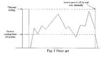
- FIG. 1of a graph of the levels of heat generated by the electrical components in a PC during a hypothetical period of use. Two horizontal divisions are shown. Amounts of heat below the passive cooling limit will not vaporize the fluid in the heat pipe and are dissipated passively. During time periods when the quantity of heat generated exceeds the passive cooling level, the fluid in the heat pipe boils and the heat pipe begins to actively transfer heat away from the electrical components and to the heat dissipater. It is obvious that usages such as those requiring frequent hard drive activity or CD access generate-more heat than typing in a word processing program. Therefore, the graph shows a typical series of peaks and valleys representing periods of higher and lower demands being placed on the system, and therefore higher and lower quantities of heat being generated.
- the entire thermal modulemust be designed around a thermal ceiling, the maximum quantity of heat that can be produced without damaging the electrical components.
- This thermal ceiling characteristic of the prior art thermal modulemakes it difficult to reduce the size of a thermal module, including the heat dissipater, a relatively large component occupying much needed space in many smaller applications.
- manufacturersface a serious conflict between the demand for a smaller product and the need to provide a large enough heat dissipater to accommodate the thermal ceilings in today's PCs.
- the claimed inventionincludes a heat pipe for rapidly transferring heat from a heat absorber to a heat dissipater, and a heat storage also in flush contact with the heat pipe.
- the heat storageincludes a phase change material (PCM) that changes from a solid state to a liquid state at a predetermined and specific temperature approximately corresponding to a reasonable thermal target.
- PCMphase change material
- a flexible, thermally and electrically insulated casing inclosing the PCMallows it to be placed in small areas between the electrical components, occupying no more than what is normally wasted space.
- phase change materialto temporarily store excess heat in a system, allows a smaller thermal module designed around a reasonable thermal target to provide adequate thermal protection.
- FIG. 1is a graph of heat levels generated by a PC according to a prior art.
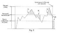
- FIG. 2is a graph of heat levels generated by a PC according to the present invention.
- FIG. 3is a structural diagram of a thermal module according to the present invention.
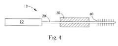
- FIG. 4is a structural diagram of another thermal module according to the present invention.
- the present invention thermal moduleincludes a heat absorber, a heat dissipater, a heat pipe, and a phase change material to temporarily store heat generated by a system in excess of a reasonable thermal target.
- the chart of FIG. 2depicts the levels of heat generated by electrical components in a typical laptop PC in a typical period of use.
- a passive cooling limitrepresents the maximum quantity of heat that can be passively dissipated by the system through natural conduction, convection, or radiation.
- the thermal ceilingrepresents the maximum amount of heat that can be produced and tolerated by the system without damaging the electrical components. Above the passive cooling limit and below the thermal ceiling is the reasonable thermal target.
- Items 1 b and 2 b of FIG. 2represent the stored heat 1 a , 2 a after it has been released back into the system.
- the areas of the regions 1 a and 1 bare equal as are the areas of 2 a and 2 b .
- the amount of heat absorbed by the PCMis equal to the amount of heat released by the PCM. Because the thermal module is designed to adequately actively dissipate levels of generated heat up to the reasonable thermal target, when the generation of heat falls below the thermal target, the thermal module is clearly able to additionally dissipate any heat that may be in storage.
- the heat storagecomprises a phase change material to temporarily absorb the excess heat.
- a PCMsuch as wax- 60 changes from a solid state to a liquid state between 53-60 degrees Celsius.
- the wax- 60has a latent heat of 264 J/g and the density of wax- 60 is 1105 cm 3 /kg. This translates into 100 grams of wax- 60 being able to absorb 264,000 Joules (7.3 Watt-Hours) of heat while changing from a solid to a liquid. Another way to say it is that 100 grams of wax- 60 can absorb 7.3 Watts of excess heat for an hour with minimal change in volume.
- wax- 60is only to be considered an example PCM in the present invention.
- the PCMcould be another substance, such as paraffin wax, H 2 O, NA 2 S 2 +5 H 2 O, Neopentyl glycol, etc.
- the change from a solid state to a liquid stateis also only an example phase change. However, the change from a solid state to a liquid state has the distinct advantage of absorbing a relatively large amount of heat with a minimal change in volume.
- the PCMcan be enclosed in a flexible casing made of some electrically and thermally insulated material and can be of any shape or size.
- the electrically and thermally insulated casingallows the PCM to be placed in unused gaps between existing system components without requiring additional space or system redesign.
- FIG. 3is a structural diagram of a thermal module 6 according to the present invention.
- FIG. 4is a structural diagram of another thermal module 8 according to the present invention.
- the thermal module 6 , 8comprises a heat absorber 10 , a heat pipe 20 , a heat storage 30 , and a heat dissipater 40 .
- the heat pipe 20is conventional in nature and is used to rapidly transfer heat from the heat absorber 10 to the heat dissipater 40 .
- the heat dissipater 40 of the thermal module 6is fixed to the heat pipe 20 between the heat absorber 10 and the heat storage 30 as shown in FIG. 3 .
- the heat storage 30 of the thermal module 8is fixed to the heat pipe 20 between the heat absorber 10 and the heat dissipater 40 as shown in FIG. 4 .
- the operating principles of the heat pipe 20 , the heat absorber 10 , and the heat dissipater 40are well know in the art and will not be further elaborated on here.
- the heat storage 30includes a PCM at least partially enclosed in an electrically and thermally insulated, flexible casing. An area of the PCM is in flush contact with the heat pipe 20 allowing high heat conductivity and low thermal resistance between the heat pipe 20 and the PCM.
- the level of generated heatis below the passive cooling limit. Soon the system begins to generate heat in excess of the passive cooling limit and less than the thermal target. At this point, the fluid in the heat absorber 10 end of the heat pipe 20 begins to vaporize, quickly transporting heat from the heat absorber 10 to the heat dissipater 40 . Because the PCM in the heat storage 30 does not change from a solid to a liquid until the thermal target has been reached, relatively little energy is absorbed by the PCM and the vast majority is removed from the system by the heat dissipater 40 .
- the PCM in the heat storage 30begins to change from a solid state into a liquid state, absorbing heat in excess of the thermal target in the process.
- the heat pipe 20continues to transfer heat to both the heat dissipater 40 and the PCM.
- the heat dissipater 40continues to dispose of amounts of heat up to the thermal target while amounts of heat in excess of the thermal target are temporarily absorbed through the melting process of the PCM.
- the heat pipe 20continues to carry heat from the heat absorber 10 to the heat dissipater 40 .
- the level of heatis below the thermal target and the freezing point of the PCM, the PCM begins to re-solidify, releasing stored heat in the process. Because the heat dissipater 40 is able to dispose of more heat than is currently being generated by the system, the heat dissipater 40 can also dispose of the released stored heat adequately.
Landscapes
- Engineering & Computer Science (AREA)
- Physics & Mathematics (AREA)
- Power Engineering (AREA)
- General Physics & Mathematics (AREA)
- Computer Hardware Design (AREA)
- Microelectronics & Electronic Packaging (AREA)
- Condensed Matter Physics & Semiconductors (AREA)
- Life Sciences & Earth Sciences (AREA)
- Sustainable Development (AREA)
- Thermal Sciences (AREA)
- Mechanical Engineering (AREA)
- General Engineering & Computer Science (AREA)
- Cooling Or The Like Of Electrical Apparatus (AREA)
- Cooling Or The Like Of Semiconductors Or Solid State Devices (AREA)
Abstract
Description
1. Field of the Invention
The present invention relates to a thermal module,.more specifically, a thermal module that uses a phase change material to temporarily store excess heat.
2. Description of the Prior Art
Quantities of heat generated by modern electrical components are often large enough to severely damage or destroy the components that generate the heat if proper precautions are not taken. These precautionary measures range from passive heat sinks to liquid refrigeration systems, but all have one common purpose, to transfer heat away from the generating device.
A well-known approach is to enlist the aid of a heat pipe. The conventional heat pipe is a hollow, partially evacuated tube. Inside the tube is a wick-like structure composed of a copper mesh or a similarly functioning component saturated with a predetermined fluid. When an end of the heat pipe is exposed to a heat source, the contained fluid at that end of the heat pipe boils, rapidly transferring heat to a cooler end of the heat pipe where the gas condenses. The condensed gas is sucked back to the region of highest heat through a capillary action of the wicks. This process effectively transfers heat many times quicker and farther than could be done by using a solid bar of a high heat conducting substance such as copper.
Many variations of heat pipes, including looped heat pipes, are used in varying situations with varying degrees of success. One of the most common uses of a heat pipe is to rapidly transfer heat from an electrical component to a heat dissipater, often a fanned or passive heat dissipater similar to a finned heat sink. Efficiency of such a system dictates that the heat dissipater must be able to dispose of unwanted heat about as rapidly as it is absorbed by the heat pipe, otherwise the related temperatures will continue to climb. In a prior art thermal module, this ability to dissipate heat as quickly as heat is absorbed is critical. If the temperature inside the condensing portion of the heat pipe exceeds the boiling point of the internal fluid, even temporarily, the heat pipe fails to function as intended and damage to related electrical components is a likely result.
Please refer to FIG. 1 of a graph of the levels of heat generated by the electrical components in a PC during a hypothetical period of use. Two horizontal divisions are shown. Amounts of heat below the passive cooling limit will not vaporize the fluid in the heat pipe and are dissipated passively. During time periods when the quantity of heat generated exceeds the passive cooling level, the fluid in the heat pipe boils and the heat pipe begins to actively transfer heat away from the electrical components and to the heat dissipater. It is obvious that usages such as those requiring frequent hard drive activity or CD access generate-more heat than typing in a word processing program. Therefore, the graph shows a typical series of peaks and valleys representing periods of higher and lower demands being placed on the system, and therefore higher and lower quantities of heat being generated.
However, because the efficiency of the system dictates that the heat dissipater must be able to dispose of unwanted heat about as rapidly as it is absorbed by the heat pipe, the entire thermal module must be designed around a thermal ceiling, the maximum quantity of heat that can be produced without damaging the electrical components. This thermal ceiling characteristic of the prior art thermal module makes it difficult to reduce the size of a thermal module, including the heat dissipater, a relatively large component occupying much needed space in many smaller applications. In fact, because faster CPUs generally generate larger amounts of heat, manufacturers face a serious conflict between the demand for a smaller product and the need to provide a large enough heat dissipater to accommodate the thermal ceilings in today's PCs.
It is therefore a primary objective of the claimed invention to disclose a thermal module whose design is not dictated by a thermal ceiling, allowing the use of a smaller heat dissipater, while providing adequate thermal protection to the related electrical components.
The claimed invention includes a heat pipe for rapidly transferring heat from a heat absorber to a heat dissipater, and a heat storage also in flush contact with the heat pipe. The heat storage includes a phase change material (PCM) that changes from a solid state to a liquid state at a predetermined and specific temperature approximately corresponding to a reasonable thermal target. A flexible, thermally and electrically insulated casing inclosing the PCM allows it to be placed in small areas between the electrical components, occupying no more than what is normally wasted space.
It is an advantage of the claimed invention that the use of the phase change material, to temporarily store excess heat in a system, allows a smaller thermal module designed around a reasonable thermal target to provide adequate thermal protection.
These and other objectives of the present invention will no doubt become obvious to those of ordinary skill in the art after -reading the following detailed description of the preferred embodiment, which is illustrated in the various figures and drawings.
FIG. 1 is a graph of heat levels generated by a PC according to a prior art.
FIG. 2 is a graph of heat levels generated by a PC according to the present invention.
FIG. 3 is a structural diagram of a thermal module according to the present invention.
FIG. 4 is a structural diagram of another thermal module according to the present invention.
The present invention thermal module includes a heat absorber, a heat dissipater, a heat pipe, and a phase change material to temporarily store heat generated by a system in excess of a reasonable thermal target.
The chart of FIG. 2 depicts the levels of heat generated by electrical components in a typical laptop PC in a typical period of use. There are three horizontally divided areas, a passive cooling limit, a reasonable thermal target, and a thermal ceiling. The passive cooling limit represents the maximum quantity of heat that can be passively dissipated by the system through natural conduction, convection, or radiation. The thermal ceiling represents the maximum amount of heat that can be produced and tolerated by the system without damaging the electrical components. Above the passive cooling limit and below the thermal ceiling is the reasonable thermal target.
All computer systems undergo fluctuations in the intensity of demands placed on the system and therefore the quantity of heat produced. The most obvious example of a high demand use of the system is a program that requires intensive CPU utilization and frequent high-speed disk or CD access, such as merely playing a video. System demands during a word processing session, or more dramatically a standby state, are obviously lighter and result in a smaller quantity of heat being produced than when in a high demand situation. Therefore, the quantity of heat generated by the system during a typical period of use fluctuates as illustrated in FIG.2.
It is obvious from the chart that designing a thermal module around the thermal ceiling results in excess thermal protection in all but extreme situations. Therefore the present invention replaces the concept of this seldom used thermal ceiling with a more practical, reasonable thermal target better representing the amount of heat generated by the system under normal operating conditions. Quantities of heat below the reasonable thermal target are absorbed and transferred via the heat pipe to the heat dissipater normally. When the system temporarily generates heat in excess of the thermal target, theexcess heat 1a,2ais temporarily stored in the heat storage. During this time, amounts of heat up to the thermal target continue to be dissipated normally via the thermal dissipater while only theheat 1a,2ain excess of the thermal target is stored. When the system's generation of heat returns to a less extreme level and again falls below the thermal target, the storedheat 1a,2ais released back into the system to be dissipated normally.
In the preferred embodiment of the present invention, the heat storage comprises a phase change material to temporarily absorb the excess heat. A PCM such as wax-60 changes from a solid state to a liquid state between 53-60 degrees Celsius. The wax-60 has a latent heat of 264 J/g and the density of wax-60 is 1105 cm3/kg. This translates into 100 grams of wax-60 being able to absorb 264,000 Joules (7.3 Watt-Hours) of heat while changing from a solid to a liquid. Another way to say it is that 100 grams of wax-60 can absorb 7.3 Watts of excess heat for an hour with minimal change in volume.
The use of wax-60 is only to be considered an example PCM in the present invention. The PCM could be another substance, such as paraffin wax, H2O, NA2S2+5 H2O, Neopentyl glycol, etc. The change from a solid state to a liquid state is also only an example phase change. However, the change from a solid state to a liquid state has the distinct advantage of absorbing a relatively large amount of heat with a minimal change in volume.
The PCM can be enclosed in a flexible casing made of some electrically and thermally insulated material and can be of any shape or size. When combined with the constant volume characteristic stated above, the electrically and thermally insulated casing allows the PCM to be placed in unused gaps between existing system components without requiring additional space or system redesign.
The operation of the present invention can best be seen in FIG.3 and FIG.4. FIG. 3 is a structural diagram of athermal module 6 according to the present invention. FIG. 4 is a structural diagram of anotherthermal module 8 according to the present invention. Thethermal module heat absorber 10, aheat pipe 20, aheat storage 30, and aheat dissipater 40. Theheat pipe 20 is conventional in nature and is used to rapidly transfer heat from theheat absorber 10 to theheat dissipater 40. Theheat dissipater 40 of thethermal module 6 is fixed to theheat pipe 20 between theheat absorber 10 and theheat storage 30 as shown in FIG.3. However, theheat storage 30 of thethermal module 8 is fixed to theheat pipe 20 between theheat absorber 10 and theheat dissipater 40 as shown in FIG.4. The operating principles of theheat pipe 20, theheat absorber 10, and theheat dissipater 40 are well know in the art and will not be further elaborated on here.
Theheat storage 30 includes a PCM at least partially enclosed in an electrically and thermally insulated, flexible casing. An area of the PCM is in flush contact with theheat pipe 20 allowing high heat conductivity and low thermal resistance between theheat pipe 20 and the PCM.
When the laptop is initially turned on, the level of generated heat is below the passive cooling limit. Soon the system begins to generate heat in excess of the passive cooling limit and less than the thermal target. At this point, the fluid in theheat absorber 10 end of theheat pipe 20 begins to vaporize, quickly transporting heat from theheat absorber 10 to theheat dissipater 40. Because the PCM in theheat storage 30 does not change from a solid to a liquid until the thermal target has been reached, relatively little energy is absorbed by the PCM and the vast majority is removed from the system by theheat dissipater 40.
Occasionally, during a period of intense demand on system resources, the heat generated within the system increases to a value exceeding the thermal target. The PCM in theheat storage 30 begins to change from a solid state into a liquid state, absorbing heat in excess of the thermal target in the process. Theheat pipe 20 continues to transfer heat to both theheat dissipater 40 and the PCM. Theheat dissipater 40 continues to dispose of amounts of heat up to the thermal target while amounts of heat in excess of the thermal target are temporarily absorbed through the melting process of the PCM.
When the intensity of demands on system resources returns to normal and therefore the production of heat within the system again falls below the thermal target, theheat pipe 20 continues to carry heat from theheat absorber 10 to theheat dissipater 40. However, because the level of heat is below the thermal target and the freezing point of the PCM, the PCM begins to re-solidify, releasing stored heat in the process. Because theheat dissipater 40 is able to dispose of more heat than is currently being generated by the system, theheat dissipater 40 can also dispose of the released stored heat adequately.
The cycle of storing excess heat during periods of high heat generation and releasing the stored heat during periods of lower heat generation can be repeated as often as required and indefinitely. The use of the PCM to temporarily store heat produced in excess of the reasonable thermal target and releasing the stored heat when the system generates a lower level of heat is clearly more efficient than the prior art. This feature of the present invention offers a distinct advantage over the prior art in allowing a reduction in the size of the thermal module while maintaining adequate thermal protection.
Those skilled in the art will readily observe that numerous modifications and alterations of the device may be made while retaining the teachings of the invention. Although this disclosure discusses a thermal module in a laptop computer, the application of the present invention is not limited to a laptop PC. For example, all types of computers have heat dissipation concerns addressed by the present invention, as do many other kinds of devices. Additionally, the use of a plurality of types of PCMs for heat storage that change from one physical state to another physical state at differing temperatures should also be considered within the scope of the present invention. Accordingly, the above disclosure should be construed as limited only by the metes and bounds of the appended claims.
Claims (15)
1. A thermal module for dissipating heat in a laptop computer, the thermal module comprising:
a heat pipe for rapidly transferring heat;
a heat absorber disposed at one end of the heat pipe for absorbing heat from a heat generating electrical component;
a heat dissipater disposed at another end of the heat pipe for dissipating the heat; and
a heat storage disposed at a section of the heat pipe between the heat absorber and the heat dissipater, the heat storage comprising a thermally and electrically insulated casing;
wherein the electrically and thermally insulated casing allows the heat storage to be placed in unused gaps between existing system components without requiring additional space or system redesign.
2. The thermal module ofclaim 1 wherein the heat storage is fixed flush against all surfaces contacting the heat pipe and not in physical contact with the heat absorber and not in physical contact with the heat dissipater.
3. The thermal module ofclaim 1 wherein the heat storage is not in physical contact with the heat dissipater.
4. The thermal module ofclaim 1 wherein the casing is flexible.
5. The thermal module ofclaim 1 wherein the heat storage is not in physical contact with the heat absorber.
6. The thermal module ofclaim 1 wherein the casing at least partially encloses a first phase change material, an area of the first phase change material being in flush contact with the heat pipe.
7. The thermal module ofclaim 6 wherein the first phase change material is selected from the group consisting of wax, water, neopentyl glycol (NPG), and Na2S2O3+5H2O.
8. The thermal module ofclaim 6 wherein the first phase change material changes from a solid state to a liquid state at a first predetermined temperature.
9. The thermal module ofclaim 8 further comprising a second phase change material disposed within the heat pipe.
10. The thermal module ofclaim 9 wherein the second phase change material changes from a liquid state to a gaseous state at a second predetermined temperature.
11. The thermal module ofclaim 10 wherein the first predetermined temperature is higher than the second predetermined temperature.
12. A thermal module for dissipating heat in a laptop computer, the thermal module comprising:
a heat generating electrical component;
a heat sink capable of continuously dissipating a maximum of a predefined reasonable thermal target quantity of heat at a predefined temperature, the reasonable thermal target being less then a maximum quantity of heat generated by the electrical component under operating conditions;
a heat pipe for transferring heat from the electrical component to the heat sink, one end of the heat pipe being in thermal contact with the heat generating electrical component, another end of the heat pipe being in thermal contact with the heat sink;
a heat storage device fixed to the heat pipe between the heat generating electrical component and the heat sink; and
a phase change material disposed within the heat storage device, an area of the phase change material being in flush contact with the heat pipe, the phase change material changing from solid state to a liquid state at approximately the predefined temperature.
13. The thermal module ofclaim 12 wherein the heat storage device comprises an electrically and thermally insulated casing.
14. A method for reducing the size of a heat sink in a laptop computer, the method comprising:
generating heat with an electrical component;
utilizing a heat pipe to transfer the heat from the heat generating electrical component to the heat sink;
utilizing at least on gap between components of the laptop computer to hold a predetermined quantity of phase change material, the phase change material being at least partially enclosed by a thermally and electrically insulated casing, an area of the phase change material being in flush contact with the heat pipe between the heat sink and the heat generating electrical component;
storing a portion of the heat in the phase change material during periods of high heat generation; and
releasing the stored heat during periods of low heat generation.
15. The method ofclaim 14 wherein the components forming the gap between components of the laptop computer utilized to hold the predetermined quantity of phase change material are electrical components.
Priority Applications (4)
| Application Number | Priority Date | Filing Date | Title |
|---|---|---|---|
| US10/064,464US6631755B1 (en) | 2002-07-17 | 2002-07-17 | Thermal module with temporary heat storage |
| TW091122914ATWI241473B (en) | 2002-07-17 | 2002-10-03 | Thermal module with temporary heat storage |
| US10/065,430US6971443B2 (en) | 2002-07-17 | 2002-10-17 | Thermal module with temporary heat storage |
| CNB021468869ACN1235113C (en) | 2002-07-17 | 2002-10-18 | Cooling module with heat storage |
Applications Claiming Priority (1)
| Application Number | Priority Date | Filing Date | Title |
|---|---|---|---|
| US10/064,464US6631755B1 (en) | 2002-07-17 | 2002-07-17 | Thermal module with temporary heat storage |
Related Child Applications (1)
| Application Number | Title | Priority Date | Filing Date |
|---|---|---|---|
| US10/065,430DivisionUS6971443B2 (en) | 2002-07-17 | 2002-10-17 | Thermal module with temporary heat storage |
Publications (1)
| Publication Number | Publication Date |
|---|---|
| US6631755B1true US6631755B1 (en) | 2003-10-14 |
Family
ID=28789701
Family Applications (2)
| Application Number | Title | Priority Date | Filing Date |
|---|---|---|---|
| US10/064,464Expired - LifetimeUS6631755B1 (en) | 2002-07-17 | 2002-07-17 | Thermal module with temporary heat storage |
| US10/065,430Expired - Fee RelatedUS6971443B2 (en) | 2002-07-17 | 2002-10-17 | Thermal module with temporary heat storage |
Family Applications After (1)
| Application Number | Title | Priority Date | Filing Date |
|---|---|---|---|
| US10/065,430Expired - Fee RelatedUS6971443B2 (en) | 2002-07-17 | 2002-10-17 | Thermal module with temporary heat storage |
Country Status (3)
| Country | Link |
|---|---|
| US (2) | US6631755B1 (en) |
| CN (1) | CN1235113C (en) |
| TW (1) | TWI241473B (en) |
Cited By (87)
| Publication number | Priority date | Publication date | Assignee | Title |
|---|---|---|---|---|
| US20020144811A1 (en)* | 2001-01-13 | 2002-10-10 | Chou Der Jeou | Phase-change heat reservoir device for transient thermal management |
| US20030056936A1 (en)* | 2001-09-26 | 2003-03-27 | Lindemuth James E. | Heat pipe system for cooling flywheel energy storage systems |
| US20050141194A1 (en)* | 2003-12-29 | 2005-06-30 | International Business Machines Corporation | Acoustic and thermal energy management system |
| US20050207120A1 (en)* | 2004-03-16 | 2005-09-22 | Industrial Technology Research Institute | Thermal module with heat reservoir and method of applying the same on electronic products |
| US20050280987A1 (en)* | 2004-06-07 | 2005-12-22 | Kwitek Benjamin J | Phase change materials as a heat sink for computers |
| US20060151146A1 (en)* | 2001-01-26 | 2006-07-13 | Chou Der J | Phase-change heat reservoir device for transient thermal management |
| US7086247B2 (en) | 2004-08-31 | 2006-08-08 | International Business Machines Corporation | Cooling system and method employing auxiliary thermal capacitor unit for facilitating continuous operation of an electronics rack |
| US20060289149A1 (en)* | 2005-06-24 | 2006-12-28 | Foxconn Technology Co., Ltd. | Heat dissipating device with heat reservoir |
| WO2008001004A1 (en)* | 2006-06-28 | 2008-01-03 | Astrium Sas | Capillary pumped diphasic fluid loop passive thermal control device with heat capacity |
| US7316262B1 (en)* | 2004-01-26 | 2008-01-08 | Rini Technologies, Inc. | Method and apparatus for absorbing thermal energy |
| US20080084666A1 (en)* | 2006-10-06 | 2008-04-10 | Honeywell International, Inc. | Liquid cooled electronic chassis having a plurality of phase change material reservoirs |
| US20080104971A1 (en)* | 2006-11-03 | 2008-05-08 | Ls Energy Solutions, Inc | Method and apparatus for thermal storage using heat pipes |
| US7505269B1 (en) | 2007-10-11 | 2009-03-17 | Valere Power Inc. | Thermal energy storage transfer system |
| US20090071628A1 (en)* | 2007-09-13 | 2009-03-19 | Forcecon Technology Co., Ltd. | Heat-radiating device with composite radiation efficiency |
| US20090109623A1 (en)* | 2007-10-31 | 2009-04-30 | Forcecon Technology Co., Ltd. | Heat-radiating module with composite phase-change heat-radiating efficiency |
| US20090180250A1 (en)* | 2008-01-11 | 2009-07-16 | Airbus Deutschland Gmbh | Peak-load cooling of electronic components by phase-change materials |
| US20100038053A1 (en)* | 2008-08-15 | 2010-02-18 | Maxik Fredric S | Sustainable endothermic heat stripping method and apparatus |
| US7882888B1 (en)* | 2005-02-23 | 2011-02-08 | Swales & Associates, Inc. | Two-phase heat transfer system including a thermal capacitance device |
| US20110308762A1 (en)* | 2010-06-22 | 2011-12-22 | Spero Alan J | High energy density thermal storage device and method |
| EP2505913A1 (en)* | 2011-03-30 | 2012-10-03 | Nxp B.V. | An active thermal management device and thermal management method |
| US20130186596A1 (en)* | 2012-01-23 | 2013-07-25 | Microsoft Corporation | Heat transfer device with phase change material |
| US20130264023A1 (en)* | 2012-04-09 | 2013-10-10 | Sgl Carbon Se | Latent heat storage device with phase change material and graphite matrix |
| US8893513B2 (en) | 2012-05-07 | 2014-11-25 | Phononic Device, Inc. | Thermoelectric heat exchanger component including protective heat spreading lid and optimal thermal interface resistance |
| US8991194B2 (en) | 2012-05-07 | 2015-03-31 | Phononic Devices, Inc. | Parallel thermoelectric heat exchange systems |
| US9223138B2 (en) | 2011-12-23 | 2015-12-29 | Microsoft Technology Licensing, Llc | Pixel opacity for augmented reality |
| US9297996B2 (en) | 2012-02-15 | 2016-03-29 | Microsoft Technology Licensing, Llc | Laser illumination scanning |
| US9304235B2 (en) | 2014-07-30 | 2016-04-05 | Microsoft Technology Licensing, Llc | Microfabrication |
| US9311909B2 (en) | 2012-09-28 | 2016-04-12 | Microsoft Technology Licensing, Llc | Sensed sound level based fan speed adjustment |
| US9372347B1 (en) | 2015-02-09 | 2016-06-21 | Microsoft Technology Licensing, Llc | Display system |
| US9423360B1 (en) | 2015-02-09 | 2016-08-23 | Microsoft Technology Licensing, Llc | Optical components |
| US9429692B1 (en) | 2015-02-09 | 2016-08-30 | Microsoft Technology Licensing, Llc | Optical components |
| US20160250906A1 (en)* | 2015-02-27 | 2016-09-01 | Mahle International Gmbh | Hvac system for electric vehicle with driving range extension |
| US9476651B2 (en) | 2014-12-15 | 2016-10-25 | General Electric Company | Thermal management system |
| US9513480B2 (en) | 2015-02-09 | 2016-12-06 | Microsoft Technology Licensing, Llc | Waveguide |
| US9535253B2 (en) | 2015-02-09 | 2017-01-03 | Microsoft Technology Licensing, Llc | Display system |
| US9578318B2 (en) | 2012-03-14 | 2017-02-21 | Microsoft Technology Licensing, Llc | Imaging structure emitter calibration |
| US9581820B2 (en) | 2012-06-04 | 2017-02-28 | Microsoft Technology Licensing, Llc | Multiple waveguide imaging structure |
| US9593871B2 (en) | 2014-07-21 | 2017-03-14 | Phononic Devices, Inc. | Systems and methods for operating a thermoelectric module to increase efficiency |
| US9606586B2 (en) | 2012-01-23 | 2017-03-28 | Microsoft Technology Licensing, Llc | Heat transfer device |
| US9717981B2 (en) | 2012-04-05 | 2017-08-01 | Microsoft Technology Licensing, Llc | Augmented reality and physical games |
| US9726887B2 (en) | 2012-02-15 | 2017-08-08 | Microsoft Technology Licensing, Llc | Imaging structure color conversion |
| US9779643B2 (en) | 2012-02-15 | 2017-10-03 | Microsoft Technology Licensing, Llc | Imaging structure emitter configurations |
| US9827209B2 (en) | 2015-02-09 | 2017-11-28 | Microsoft Technology Licensing, Llc | Display system |
| CN107560005A (en)* | 2017-09-13 | 2018-01-09 | 珠海格力电器股份有限公司 | Radiating assembly and air conditioner |
| US9909448B2 (en) | 2015-04-15 | 2018-03-06 | General Electric Company | Gas turbine engine component with integrated heat pipe |
| US9936608B2 (en)* | 2015-12-17 | 2018-04-03 | Commissariat A L'energie Atomique Et Aux Energies Alternatives | Composite heat absorption device and method for obtaining same |
| JP2018511523A (en)* | 2015-03-30 | 2018-04-26 | ワールドビュー・サテライツ・リミテッド | Passive thermal system with coupled heat pipe and phase change material and satellite incorporating it |
| US10018844B2 (en) | 2015-02-09 | 2018-07-10 | Microsoft Technology Licensing, Llc | Wearable image display system |
| US10191515B2 (en) | 2012-03-28 | 2019-01-29 | Microsoft Technology Licensing, Llc | Mobile device light guide display |
| US10192358B2 (en) | 2012-12-20 | 2019-01-29 | Microsoft Technology Licensing, Llc | Auto-stereoscopic augmented reality display |
| GB2542696B (en)* | 2015-09-09 | 2019-03-27 | Gen Electric | Thermal management system |
| US10254942B2 (en) | 2014-07-31 | 2019-04-09 | Microsoft Technology Licensing, Llc | Adaptive sizing and positioning of application windows |
| US10317677B2 (en) | 2015-02-09 | 2019-06-11 | Microsoft Technology Licensing, Llc | Display system |
| US10356945B2 (en) | 2015-01-08 | 2019-07-16 | General Electric Company | System and method for thermal management using vapor chamber |
| US10388073B2 (en) | 2012-03-28 | 2019-08-20 | Microsoft Technology Licensing, Llc | Augmented reality light guide display |
| US10458683B2 (en) | 2014-07-21 | 2019-10-29 | Phononic, Inc. | Systems and methods for mitigating heat rejection limitations of a thermoelectric module |
| US10502876B2 (en) | 2012-05-22 | 2019-12-10 | Microsoft Technology Licensing, Llc | Waveguide optics focus elements |
| US10592080B2 (en) | 2014-07-31 | 2020-03-17 | Microsoft Technology Licensing, Llc | Assisted presentation of application windows |
| US10605541B1 (en)* | 2016-09-20 | 2020-03-31 | Advanced Cooling Technologies, Inc. | Heat pipe—thermal storage medium based cool storage system |
| US10660236B2 (en) | 2014-04-08 | 2020-05-19 | General Electric Company | Systems and methods for using additive manufacturing for thermal management |
| US10678412B2 (en) | 2014-07-31 | 2020-06-09 | Microsoft Technology Licensing, Llc | Dynamic joint dividers for application windows |
| US11035621B2 (en) | 2016-06-21 | 2021-06-15 | Ge Aviation Systems Llc | Electronics cooling with multi-phase heat exchange and heat spreader |
| US11068049B2 (en) | 2012-03-23 | 2021-07-20 | Microsoft Technology Licensing, Llc | Light guide display and field of view |
| CN113157072A (en)* | 2016-12-29 | 2021-07-23 | 华为技术有限公司 | Heat dissipation device and terminal equipment thereof |
| US11086216B2 (en) | 2015-02-09 | 2021-08-10 | Microsoft Technology Licensing, Llc | Generating electronic components |
| US11262821B1 (en) | 2020-12-07 | 2022-03-01 | Dell Products L.P. | Information handling system with articulated cooling fins between interleaved and separated positions |
| US11262822B1 (en) | 2020-12-07 | 2022-03-01 | Dell Products L.P. | Information handling system dynamic cooling fan articulation to manage thermal parameters |
| US11262807B1 (en) | 2020-12-11 | 2022-03-01 | Dell Products L.P. | Information handling system speaker mount under a transparent housing cover |
| US11260976B2 (en) | 2019-11-15 | 2022-03-01 | General Electric Company | System for reducing thermal stresses in a leading edge of a high speed vehicle |
| US11260953B2 (en) | 2019-11-15 | 2022-03-01 | General Electric Company | System and method for cooling a leading edge of a high speed vehicle |
| US11262820B1 (en) | 2020-12-07 | 2022-03-01 | Dell Products L.P. | Information handling system dynamic thermal behavior |
| US11267551B2 (en) | 2019-11-15 | 2022-03-08 | General Electric Company | System and method for cooling a leading edge of a high speed vehicle |
| US11320876B1 (en)* | 2020-12-07 | 2022-05-03 | Dell Products L.P. | Information handling system handle with integrated thermal rejection system |
| US11352120B2 (en) | 2019-11-15 | 2022-06-07 | General Electric Company | System and method for cooling a leading edge of a high speed vehicle |
| US11407488B2 (en) | 2020-12-14 | 2022-08-09 | General Electric Company | System and method for cooling a leading edge of a high speed vehicle |
| US11427330B2 (en) | 2019-11-15 | 2022-08-30 | General Electric Company | System and method for cooling a leading edge of a high speed vehicle |
| US11466190B2 (en)* | 2018-06-25 | 2022-10-11 | Abb Schweiz Ag | Forced air cooling system with phase change material |
| US11577817B2 (en) | 2021-02-11 | 2023-02-14 | General Electric Company | System and method for cooling a leading edge of a high speed vehicle |
| US20230081585A1 (en)* | 2021-09-16 | 2023-03-16 | Dell Products L.P. | Systems and methods for using phase change material to aid cooling of information handling resources |
| US20230100966A1 (en)* | 2019-12-03 | 2023-03-30 | Hewlett-Packard Development Company, L.P. | Processor cooling with phase change material filled shell |
| US11662712B2 (en) | 2020-12-11 | 2023-05-30 | Dell Products L.P. | Information handling system housing cover inflatable seal |
| US11733742B2 (en) | 2020-12-07 | 2023-08-22 | Dell Products L.P. | Information handling system integrated speaker with variable volume sound chamber |
| US11745847B2 (en) | 2020-12-08 | 2023-09-05 | General Electric Company | System and method for cooling a leading edge of a high speed vehicle |
| US11893163B2 (en) | 2020-12-11 | 2024-02-06 | Dell Products L.P. | Information handling system virtual and physical keyboard position coordination |
| CN118131856A (en)* | 2022-12-01 | 2024-06-04 | 荣耀终端有限公司 | Electronic device and control method thereof |
| US12040690B2 (en) | 2020-08-31 | 2024-07-16 | General Electric Company | Cooling a stator housing of an electric machine |
| US12038795B2 (en) | 2020-12-11 | 2024-07-16 | Dell Products L.P. | Information handling system visual presentation with audio vector based information |
Families Citing this family (13)
| Publication number | Priority date | Publication date | Assignee | Title |
|---|---|---|---|---|
| US8377524B2 (en) | 2005-12-27 | 2013-02-19 | Guardian Industries Corp. | High R-value window unit |
| US7845142B2 (en)* | 2005-12-27 | 2010-12-07 | Guardian Industries Corp. | High R-value window unit with vacuum IG unit and insulating frame |
| FR2929070B1 (en)* | 2008-03-18 | 2010-03-12 | Kontron Modular Computers | DEVICE FOR PREHEATING A COMPONENT COOLED BY CONDUCTION AND / OR CONVECTION |
| US9746248B2 (en)* | 2011-10-18 | 2017-08-29 | Thermal Corp. | Heat pipe having a wick with a hybrid profile |
| US8638498B2 (en) | 2012-01-04 | 2014-01-28 | David D. Bohn | Eyebox adjustment for interpupillary distance |
| TWI483099B (en)* | 2012-06-08 | 2015-05-01 | Foxconn Tech Co Ltd | Phase change type heat dissipating device |
| CN105190170B (en)* | 2013-04-24 | 2019-10-22 | 项晓东 | LED lamp cooling mechanism using three-dimensional phase change heat transfer |
| CN103940268B (en)* | 2014-04-23 | 2016-03-02 | 浙江大学 | Based on the energy storage combined type temperature-controlling system of low-temperature alloy |
| CN105828551B (en)* | 2016-04-29 | 2018-06-29 | 广东欧珀移动通信有限公司 | Rear shell and mobile terminal |
| CN107979946B (en)* | 2016-10-24 | 2020-03-06 | 全球能源互联网欧洲研究院 | A cooling system and method |
| DE102017200524A1 (en)* | 2017-01-13 | 2018-07-19 | Siemens Aktiengesellschaft | Cooling device with a heat pipe and a latent heat storage, method for producing the same and electronic circuit |
| CN106839463A (en)* | 2017-02-28 | 2017-06-13 | 北京工业大学 | Flat-plate type micro heat pipe array type solar air heat-collecting, accumulation of heat integrated apparatus |
| JP7098574B2 (en)* | 2019-05-28 | 2022-07-11 | 矢崎総業株式会社 | Heat dissipation structure |
Citations (8)
| Publication number | Priority date | Publication date | Assignee | Title |
|---|---|---|---|---|
| US2499736A (en)* | 1946-09-06 | 1950-03-07 | Kleen Nils Erland Af | Aircraft refrigeration |
| US3596713A (en)* | 1969-01-27 | 1971-08-03 | Astro Dynamics Inc | Liquid-solid heat transport system |
| US4285027A (en)* | 1979-01-12 | 1981-08-18 | Daikin Kogyo Co., Ltd. | Cooling system |
| US4415118A (en)* | 1980-05-13 | 1983-11-15 | Nissan Motor Co., Ltd. | Vehicle cabin spot heater |
| US4976308A (en)* | 1990-02-21 | 1990-12-11 | Wright State University | Thermal energy storage heat exchanger |
| US5579830A (en)* | 1995-11-28 | 1996-12-03 | Hudson Products Corporation | Passive cooling of enclosures using heat pipes |
| US6191944B1 (en)* | 1998-11-05 | 2001-02-20 | Electrovac, Fabrikation Elektrotechnischer Spezialartikel Gesellschaft M.B.H. | Heat sink for electric and/or electronic devices |
| US6260613B1 (en)* | 1999-01-05 | 2001-07-17 | Intel Corporation | Transient cooling augmentation for electronic components |
- 2002
- 2002-07-17USUS10/064,464patent/US6631755B1/ennot_activeExpired - Lifetime
- 2002-10-03TWTW091122914Apatent/TWI241473B/ennot_activeIP Right Cessation
- 2002-10-17USUS10/065,430patent/US6971443B2/ennot_activeExpired - Fee Related
- 2002-10-18CNCNB021468869Apatent/CN1235113C/ennot_activeExpired - Fee Related
Patent Citations (8)
| Publication number | Priority date | Publication date | Assignee | Title |
|---|---|---|---|---|
| US2499736A (en)* | 1946-09-06 | 1950-03-07 | Kleen Nils Erland Af | Aircraft refrigeration |
| US3596713A (en)* | 1969-01-27 | 1971-08-03 | Astro Dynamics Inc | Liquid-solid heat transport system |
| US4285027A (en)* | 1979-01-12 | 1981-08-18 | Daikin Kogyo Co., Ltd. | Cooling system |
| US4415118A (en)* | 1980-05-13 | 1983-11-15 | Nissan Motor Co., Ltd. | Vehicle cabin spot heater |
| US4976308A (en)* | 1990-02-21 | 1990-12-11 | Wright State University | Thermal energy storage heat exchanger |
| US5579830A (en)* | 1995-11-28 | 1996-12-03 | Hudson Products Corporation | Passive cooling of enclosures using heat pipes |
| US6191944B1 (en)* | 1998-11-05 | 2001-02-20 | Electrovac, Fabrikation Elektrotechnischer Spezialartikel Gesellschaft M.B.H. | Heat sink for electric and/or electronic devices |
| US6260613B1 (en)* | 1999-01-05 | 2001-07-17 | Intel Corporation | Transient cooling augmentation for electronic components |
Cited By (121)
| Publication number | Priority date | Publication date | Assignee | Title |
|---|---|---|---|---|
| US20020144811A1 (en)* | 2001-01-13 | 2002-10-10 | Chou Der Jeou | Phase-change heat reservoir device for transient thermal management |
| US6997241B2 (en)* | 2001-01-13 | 2006-02-14 | Enertron, Inc. | Phase-change heat reservoir device for transient thermal management |
| US20060151146A1 (en)* | 2001-01-26 | 2006-07-13 | Chou Der J | Phase-change heat reservoir device for transient thermal management |
| US7191820B2 (en) | 2001-01-26 | 2007-03-20 | Enertron, Inc. | Phase-change heat reservoir device for transient thermal management |
| US20030056936A1 (en)* | 2001-09-26 | 2003-03-27 | Lindemuth James E. | Heat pipe system for cooling flywheel energy storage systems |
| US6808011B2 (en)* | 2001-09-26 | 2004-10-26 | Thermal.Corp. | Heat pipe system for cooling flywheel energy storage systems |
| US7116555B2 (en)* | 2003-12-29 | 2006-10-03 | International Business Machines Corporation | Acoustic and thermal energy management system |
| US20050141194A1 (en)* | 2003-12-29 | 2005-06-30 | International Business Machines Corporation | Acoustic and thermal energy management system |
| US7316262B1 (en)* | 2004-01-26 | 2008-01-08 | Rini Technologies, Inc. | Method and apparatus for absorbing thermal energy |
| US20050207120A1 (en)* | 2004-03-16 | 2005-09-22 | Industrial Technology Research Institute | Thermal module with heat reservoir and method of applying the same on electronic products |
| US20050280987A1 (en)* | 2004-06-07 | 2005-12-22 | Kwitek Benjamin J | Phase change materials as a heat sink for computers |
| US7086247B2 (en) | 2004-08-31 | 2006-08-08 | International Business Machines Corporation | Cooling system and method employing auxiliary thermal capacitor unit for facilitating continuous operation of an electronics rack |
| US9146058B2 (en) | 2005-02-23 | 2015-09-29 | Orbital Atk, Inc. | Two-phase heat transfer system including a thermal capacitance device |
| US10259064B2 (en) | 2005-02-23 | 2019-04-16 | Northrop Grumman Innovation Systems, Inc. | Methods of forming a thermal storage unit |
| US20110132576A1 (en)* | 2005-02-23 | 2011-06-09 | Alliant Techsystems Inc. | Two-phase heat transfer system including a thermal capacitance device and related methods |
| US7882888B1 (en)* | 2005-02-23 | 2011-02-08 | Swales & Associates, Inc. | Two-phase heat transfer system including a thermal capacitance device |
| US20060289149A1 (en)* | 2005-06-24 | 2006-12-28 | Foxconn Technology Co., Ltd. | Heat dissipating device with heat reservoir |
| US7448437B2 (en)* | 2005-06-24 | 2008-11-11 | Fu Zhun Precision Industry (Shenzhen) Co., Ltd. | Heat dissipating device with heat reservoir |
| US20090288801A1 (en)* | 2006-06-28 | 2009-11-26 | Astrium Sas | Capillary Pumped Diphasic Fluid Loop Passive Thermal Control Device with Thermal Capacitor |
| FR2903222A1 (en)* | 2006-06-28 | 2008-01-04 | Eads Astrium Sas Soc Par Actio | PASSIVE THERMAL CONTROL ARRANGEMENT BASED ON DIPHASIC FLUID LOOP WITH CAPILLARY PUMPING WITH THERMAL CAPACITY. |
| WO2008001004A1 (en)* | 2006-06-28 | 2008-01-03 | Astrium Sas | Capillary pumped diphasic fluid loop passive thermal control device with heat capacity |
| US7433190B2 (en) | 2006-10-06 | 2008-10-07 | Honeywell International Inc. | Liquid cooled electronic chassis having a plurality of phase change material reservoirs |
| US20080084666A1 (en)* | 2006-10-06 | 2008-04-10 | Honeywell International, Inc. | Liquid cooled electronic chassis having a plurality of phase change material reservoirs |
| US7891575B2 (en)* | 2006-11-03 | 2011-02-22 | Sami Samuel M | Method and apparatus for thermal storage using heat pipes |
| US20080104971A1 (en)* | 2006-11-03 | 2008-05-08 | Ls Energy Solutions, Inc | Method and apparatus for thermal storage using heat pipes |
| US20090071628A1 (en)* | 2007-09-13 | 2009-03-19 | Forcecon Technology Co., Ltd. | Heat-radiating device with composite radiation efficiency |
| US7505269B1 (en) | 2007-10-11 | 2009-03-17 | Valere Power Inc. | Thermal energy storage transfer system |
| US20090109623A1 (en)* | 2007-10-31 | 2009-04-30 | Forcecon Technology Co., Ltd. | Heat-radiating module with composite phase-change heat-radiating efficiency |
| US20090180250A1 (en)* | 2008-01-11 | 2009-07-16 | Airbus Deutschland Gmbh | Peak-load cooling of electronic components by phase-change materials |
| US8631855B2 (en)* | 2008-08-15 | 2014-01-21 | Lighting Science Group Corporation | System for dissipating heat energy |
| US20100038053A1 (en)* | 2008-08-15 | 2010-02-18 | Maxik Fredric S | Sustainable endothermic heat stripping method and apparatus |
| US20110308762A1 (en)* | 2010-06-22 | 2011-12-22 | Spero Alan J | High energy density thermal storage device and method |
| US8701653B2 (en)* | 2010-06-22 | 2014-04-22 | Alan J. Spero | High energy density thermal storage device and method |
| CN102740659B (en)* | 2011-03-30 | 2015-03-25 | Nxp股份有限公司 | An active thermal management device and thermal management method |
| CN102740659A (en)* | 2011-03-30 | 2012-10-17 | Nxp股份有限公司 | An active thermal management device and thermal management method |
| US9939141B2 (en)* | 2011-03-30 | 2018-04-10 | Nxp B.V. | Active thermal management device and thermal management method |
| EP2505913A1 (en)* | 2011-03-30 | 2012-10-03 | Nxp B.V. | An active thermal management device and thermal management method |
| US20120247707A1 (en)* | 2011-03-30 | 2012-10-04 | Nxp B.V. | Active thermal management device and thermal management method |
| US9223138B2 (en) | 2011-12-23 | 2015-12-29 | Microsoft Technology Licensing, Llc | Pixel opacity for augmented reality |
| US8934235B2 (en)* | 2012-01-23 | 2015-01-13 | Microsoft Corporation | Heat transfer device with phase change material |
| US9606586B2 (en) | 2012-01-23 | 2017-03-28 | Microsoft Technology Licensing, Llc | Heat transfer device |
| US20130186596A1 (en)* | 2012-01-23 | 2013-07-25 | Microsoft Corporation | Heat transfer device with phase change material |
| US9726887B2 (en) | 2012-02-15 | 2017-08-08 | Microsoft Technology Licensing, Llc | Imaging structure color conversion |
| US9297996B2 (en) | 2012-02-15 | 2016-03-29 | Microsoft Technology Licensing, Llc | Laser illumination scanning |
| US9779643B2 (en) | 2012-02-15 | 2017-10-03 | Microsoft Technology Licensing, Llc | Imaging structure emitter configurations |
| US9578318B2 (en) | 2012-03-14 | 2017-02-21 | Microsoft Technology Licensing, Llc | Imaging structure emitter calibration |
| US9807381B2 (en) | 2012-03-14 | 2017-10-31 | Microsoft Technology Licensing, Llc | Imaging structure emitter calibration |
| US11068049B2 (en) | 2012-03-23 | 2021-07-20 | Microsoft Technology Licensing, Llc | Light guide display and field of view |
| US10191515B2 (en) | 2012-03-28 | 2019-01-29 | Microsoft Technology Licensing, Llc | Mobile device light guide display |
| US10388073B2 (en) | 2012-03-28 | 2019-08-20 | Microsoft Technology Licensing, Llc | Augmented reality light guide display |
| US9717981B2 (en) | 2012-04-05 | 2017-08-01 | Microsoft Technology Licensing, Llc | Augmented reality and physical games |
| US10478717B2 (en) | 2012-04-05 | 2019-11-19 | Microsoft Technology Licensing, Llc | Augmented reality and physical games |
| US20130264023A1 (en)* | 2012-04-09 | 2013-10-10 | Sgl Carbon Se | Latent heat storage device with phase change material and graphite matrix |
| US9234682B2 (en) | 2012-05-07 | 2016-01-12 | Phononic Devices, Inc. | Two-phase heat exchanger mounting |
| US9103572B2 (en) | 2012-05-07 | 2015-08-11 | Phononic Devices, Inc. | Physically separated hot side and cold side heat sinks in a thermoelectric refrigeration system |
| US8991194B2 (en) | 2012-05-07 | 2015-03-31 | Phononic Devices, Inc. | Parallel thermoelectric heat exchange systems |
| US9341394B2 (en) | 2012-05-07 | 2016-05-17 | Phononic Devices, Inc. | Thermoelectric heat exchange system comprising cascaded cold side heat sinks |
| US10012417B2 (en) | 2012-05-07 | 2018-07-03 | Phononic, Inc. | Thermoelectric refrigeration system control scheme for high efficiency performance |
| US9310111B2 (en) | 2012-05-07 | 2016-04-12 | Phononic Devices, Inc. | Systems and methods to mitigate heat leak back in a thermoelectric refrigeration system |
| US8893513B2 (en) | 2012-05-07 | 2014-11-25 | Phononic Device, Inc. | Thermoelectric heat exchanger component including protective heat spreading lid and optimal thermal interface resistance |
| US10502876B2 (en) | 2012-05-22 | 2019-12-10 | Microsoft Technology Licensing, Llc | Waveguide optics focus elements |
| US9581820B2 (en) | 2012-06-04 | 2017-02-28 | Microsoft Technology Licensing, Llc | Multiple waveguide imaging structure |
| US9311909B2 (en) | 2012-09-28 | 2016-04-12 | Microsoft Technology Licensing, Llc | Sensed sound level based fan speed adjustment |
| US10192358B2 (en) | 2012-12-20 | 2019-01-29 | Microsoft Technology Licensing, Llc | Auto-stereoscopic augmented reality display |
| US12150279B2 (en) | 2014-04-08 | 2024-11-19 | General Electric Company | Systems and methods for using additive manufacturing for thermal management |
| US10660236B2 (en) | 2014-04-08 | 2020-05-19 | General Electric Company | Systems and methods for using additive manufacturing for thermal management |
| US9593871B2 (en) | 2014-07-21 | 2017-03-14 | Phononic Devices, Inc. | Systems and methods for operating a thermoelectric module to increase efficiency |
| US10458683B2 (en) | 2014-07-21 | 2019-10-29 | Phononic, Inc. | Systems and methods for mitigating heat rejection limitations of a thermoelectric module |
| US9304235B2 (en) | 2014-07-30 | 2016-04-05 | Microsoft Technology Licensing, Llc | Microfabrication |
| US10254942B2 (en) | 2014-07-31 | 2019-04-09 | Microsoft Technology Licensing, Llc | Adaptive sizing and positioning of application windows |
| US10592080B2 (en) | 2014-07-31 | 2020-03-17 | Microsoft Technology Licensing, Llc | Assisted presentation of application windows |
| US10678412B2 (en) | 2014-07-31 | 2020-06-09 | Microsoft Technology Licensing, Llc | Dynamic joint dividers for application windows |
| US9909816B2 (en) | 2014-12-15 | 2018-03-06 | General Electric Company | Thermal management system |
| US9476651B2 (en) | 2014-12-15 | 2016-10-25 | General Electric Company | Thermal management system |
| US10356945B2 (en) | 2015-01-08 | 2019-07-16 | General Electric Company | System and method for thermal management using vapor chamber |
| US10317677B2 (en) | 2015-02-09 | 2019-06-11 | Microsoft Technology Licensing, Llc | Display system |
| US9372347B1 (en) | 2015-02-09 | 2016-06-21 | Microsoft Technology Licensing, Llc | Display system |
| US10018844B2 (en) | 2015-02-09 | 2018-07-10 | Microsoft Technology Licensing, Llc | Wearable image display system |
| US9513480B2 (en) | 2015-02-09 | 2016-12-06 | Microsoft Technology Licensing, Llc | Waveguide |
| US9535253B2 (en) | 2015-02-09 | 2017-01-03 | Microsoft Technology Licensing, Llc | Display system |
| US11086216B2 (en) | 2015-02-09 | 2021-08-10 | Microsoft Technology Licensing, Llc | Generating electronic components |
| US9429692B1 (en) | 2015-02-09 | 2016-08-30 | Microsoft Technology Licensing, Llc | Optical components |
| US9827209B2 (en) | 2015-02-09 | 2017-11-28 | Microsoft Technology Licensing, Llc | Display system |
| US9423360B1 (en) | 2015-02-09 | 2016-08-23 | Microsoft Technology Licensing, Llc | Optical components |
| US20160250906A1 (en)* | 2015-02-27 | 2016-09-01 | Mahle International Gmbh | Hvac system for electric vehicle with driving range extension |
| US9809083B2 (en)* | 2015-02-27 | 2017-11-07 | Mahle International Gmbh | HVAC system for electric vehicle with driving range extension |
| CN105922839A (en)* | 2015-02-27 | 2016-09-07 | 马勒国际有限公司 | HVAC system for electric vehicle with driving range extension |
| CN105922839B (en)* | 2015-02-27 | 2020-04-10 | 马勒国际有限公司 | HVAC system for electric vehicle with extended driving distance |
| US10793297B2 (en) | 2015-03-30 | 2020-10-06 | Worldvu Satellites Limited | Passive thermal system comprising combined heat pipe and phase change material and satellites incorporating same |
| EP3278048A4 (en)* | 2015-03-30 | 2018-09-05 | Worldvu Satellites Limited | Passive thermal system comprising combined heat pipe and phase change material and satellites incorporating same |
| JP2018511523A (en)* | 2015-03-30 | 2018-04-26 | ワールドビュー・サテライツ・リミテッド | Passive thermal system with coupled heat pipe and phase change material and satellite incorporating it |
| US9909448B2 (en) | 2015-04-15 | 2018-03-06 | General Electric Company | Gas turbine engine component with integrated heat pipe |
| US10386127B2 (en) | 2015-09-09 | 2019-08-20 | General Electric Company | Thermal management system |
| GB2542696B (en)* | 2015-09-09 | 2019-03-27 | Gen Electric | Thermal management system |
| US9936608B2 (en)* | 2015-12-17 | 2018-04-03 | Commissariat A L'energie Atomique Et Aux Energies Alternatives | Composite heat absorption device and method for obtaining same |
| US11035621B2 (en) | 2016-06-21 | 2021-06-15 | Ge Aviation Systems Llc | Electronics cooling with multi-phase heat exchange and heat spreader |
| US10605541B1 (en)* | 2016-09-20 | 2020-03-31 | Advanced Cooling Technologies, Inc. | Heat pipe—thermal storage medium based cool storage system |
| CN113157072A (en)* | 2016-12-29 | 2021-07-23 | 华为技术有限公司 | Heat dissipation device and terminal equipment thereof |
| CN107560005A (en)* | 2017-09-13 | 2018-01-09 | 珠海格力电器股份有限公司 | Radiating assembly and air conditioner |
| US11466190B2 (en)* | 2018-06-25 | 2022-10-11 | Abb Schweiz Ag | Forced air cooling system with phase change material |
| US11427330B2 (en) | 2019-11-15 | 2022-08-30 | General Electric Company | System and method for cooling a leading edge of a high speed vehicle |
| US11260976B2 (en) | 2019-11-15 | 2022-03-01 | General Electric Company | System for reducing thermal stresses in a leading edge of a high speed vehicle |
| US11260953B2 (en) | 2019-11-15 | 2022-03-01 | General Electric Company | System and method for cooling a leading edge of a high speed vehicle |
| US11267551B2 (en) | 2019-11-15 | 2022-03-08 | General Electric Company | System and method for cooling a leading edge of a high speed vehicle |
| US11352120B2 (en) | 2019-11-15 | 2022-06-07 | General Electric Company | System and method for cooling a leading edge of a high speed vehicle |
| US20230100966A1 (en)* | 2019-12-03 | 2023-03-30 | Hewlett-Packard Development Company, L.P. | Processor cooling with phase change material filled shell |
| US12040690B2 (en) | 2020-08-31 | 2024-07-16 | General Electric Company | Cooling a stator housing of an electric machine |
| US11262822B1 (en) | 2020-12-07 | 2022-03-01 | Dell Products L.P. | Information handling system dynamic cooling fan articulation to manage thermal parameters |
| US11320876B1 (en)* | 2020-12-07 | 2022-05-03 | Dell Products L.P. | Information handling system handle with integrated thermal rejection system |
| US11262820B1 (en) | 2020-12-07 | 2022-03-01 | Dell Products L.P. | Information handling system dynamic thermal behavior |
| US11733742B2 (en) | 2020-12-07 | 2023-08-22 | Dell Products L.P. | Information handling system integrated speaker with variable volume sound chamber |
| US11262821B1 (en) | 2020-12-07 | 2022-03-01 | Dell Products L.P. | Information handling system with articulated cooling fins between interleaved and separated positions |
| US11745847B2 (en) | 2020-12-08 | 2023-09-05 | General Electric Company | System and method for cooling a leading edge of a high speed vehicle |
| US12038795B2 (en) | 2020-12-11 | 2024-07-16 | Dell Products L.P. | Information handling system visual presentation with audio vector based information |
| US11662712B2 (en) | 2020-12-11 | 2023-05-30 | Dell Products L.P. | Information handling system housing cover inflatable seal |
| US11893163B2 (en) | 2020-12-11 | 2024-02-06 | Dell Products L.P. | Information handling system virtual and physical keyboard position coordination |
| US11262807B1 (en) | 2020-12-11 | 2022-03-01 | Dell Products L.P. | Information handling system speaker mount under a transparent housing cover |
| US11407488B2 (en) | 2020-12-14 | 2022-08-09 | General Electric Company | System and method for cooling a leading edge of a high speed vehicle |
| US11577817B2 (en) | 2021-02-11 | 2023-02-14 | General Electric Company | System and method for cooling a leading edge of a high speed vehicle |
| US20230081585A1 (en)* | 2021-09-16 | 2023-03-16 | Dell Products L.P. | Systems and methods for using phase change material to aid cooling of information handling resources |
| CN118131856A (en)* | 2022-12-01 | 2024-06-04 | 荣耀终端有限公司 | Electronic device and control method thereof |
Also Published As
| Publication number | Publication date |
|---|---|
| US20040011503A1 (en) | 2004-01-22 |
| US6971443B2 (en) | 2005-12-06 |
| CN1235113C (en) | 2006-01-04 |
| TWI241473B (en) | 2005-10-11 |
| CN1469700A (en) | 2004-01-21 |
Similar Documents
| Publication | Publication Date | Title |
|---|---|---|
| US6631755B1 (en) | Thermal module with temporary heat storage | |
| US7191820B2 (en) | Phase-change heat reservoir device for transient thermal management | |
| US6997241B2 (en) | Phase-change heat reservoir device for transient thermal management | |
| CN109074140B (en) | Passive thermal management system with phase change material | |
| US6260613B1 (en) | Transient cooling augmentation for electronic components | |
| US6917522B1 (en) | Apparatus and method for cooling integrated circuit devices | |
| US7116555B2 (en) | Acoustic and thermal energy management system | |
| US6717811B2 (en) | Heat dissipating apparatus for interface cards | |
| JP4567777B2 (en) | Electronic device and thermal connector used for it | |
| US12402279B2 (en) | Heat dissipation structure and electronic device | |
| US20200110450A1 (en) | Heat dissipation module | |
| US11239133B2 (en) | Apparatus and method for dissipating heat in multiple semiconductor device modules | |
| WO2002010661A1 (en) | High-efficiency computer thermal management apparatus and method | |
| CN112256113A (en) | Flat heat pipe type CPU heat dissipation device based on thermoelectric refrigeration | |
| Zuo et al. | Combined pulsating and capillary heat pipe mechanism for cooling of high heat flux electronics | |
| US7861768B1 (en) | Heat sink | |
| US20160353610A1 (en) | Heat pipe with near-azeotropic binary fluid | |
| CN113891620B (en) | Heat abstractor and electronic equipment | |
| CN108990365A (en) | Radiator structure, shell and electronic equipment | |
| CN115190736A (en) | Computing equipment and cabinet | |
| Mochizuki et al. | Revolution in fan heat sink cooling technology to extend and maximize air cooling for high performance processors in laptop/desktop/server application | |
| CN109588021A (en) | Electronic equipment | |
| US20120118540A1 (en) | Heat transfer systems and methods | |
| US8783333B1 (en) | Cooling system | |
| CN210835950U (en) | Heat dissipation device and electronic equipment |
Legal Events
| Date | Code | Title | Description |
|---|---|---|---|
| AS | Assignment | Owner name:COMPAL ELECTRONICS, INC., TAIWAN Free format text:ASSIGNMENT OF ASSIGNORS INTEREST;ASSIGNORS:KUNG, SHAO-TSU;LIU, CHEN-HUA;REEL/FRAME:012893/0482 Effective date:20020716 | |
| STCF | Information on status: patent grant | Free format text:PATENTED CASE | |
| FPAY | Fee payment | Year of fee payment:4 | |
| FPAY | Fee payment | Year of fee payment:8 | |
| FPAY | Fee payment | Year of fee payment:12 |