US6631334B2 - Pressure-based mass flow controller system - Google Patents
Pressure-based mass flow controller systemDownload PDFInfo
- Publication number
- US6631334B2 US6631334B2US09/748,472US74847200AUS6631334B2US 6631334 B2US6631334 B2US 6631334B2US 74847200 AUS74847200 AUS 74847200AUS 6631334 B2US6631334 B2US 6631334B2
- Authority
- US
- United States
- Prior art keywords
- flow
- pressure
- flow path
- manifold
- actual
- Prior art date
- Legal status (The legal status is an assumption and is not a legal conclusion. Google has not performed a legal analysis and makes no representation as to the accuracy of the status listed.)
- Expired - Lifetime
Links
- 238000011144upstream manufacturingMethods0.000claimsabstractdescription84
- 238000009530blood pressure measurementMethods0.000claimsabstractdescription35
- 238000000034methodMethods0.000claimsdescription14
- 238000009529body temperature measurementMethods0.000claimsdescription9
- 238000012886linear functionMethods0.000claimsdescription7
- 238000010438heat treatmentMethods0.000claimsdescription5
- 230000003247decreasing effectEffects0.000claims3
- 239000012530fluidSubstances0.000abstractdescription46
- 239000002243precursorSubstances0.000description19
- 239000000376reactantSubstances0.000description11
- 230000008569processEffects0.000description10
- 230000006870functionEffects0.000description9
- 230000008901benefitEffects0.000description7
- 239000000463materialSubstances0.000description6
- 230000004044responseEffects0.000description6
- 239000004065semiconductorSubstances0.000description6
- 239000007787solidSubstances0.000description6
- 239000007789gasSubstances0.000description5
- 239000007788liquidSubstances0.000description4
- 238000004519manufacturing processMethods0.000description4
- 238000005259measurementMethods0.000description4
- 238000013461designMethods0.000description3
- 238000010586diagramMethods0.000description3
- 238000012986modificationMethods0.000description2
- 230000004048modificationEffects0.000description2
- 238000012545processingMethods0.000description2
- IJGRMHOSHXDMSA-UHFFFAOYSA-NAtomic nitrogenChemical compoundN#NIJGRMHOSHXDMSA-UHFFFAOYSA-N0.000description1
- 238000004364calculation methodMethods0.000description1
- 238000005094computer simulationMethods0.000description1
- 229910001873dinitrogenInorganic materials0.000description1
- 238000011143downstream manufacturingMethods0.000description1
- 239000012705liquid precursorSubstances0.000description1
- 230000007246mechanismEffects0.000description1
- 239000002904solventSubstances0.000description1
- 231100000331toxicToxicity0.000description1
- 230000002588toxic effectEffects0.000description1
- 238000012546transferMethods0.000description1
- 238000005019vapor deposition processMethods0.000description1
Images


Classifications
- H—ELECTRICITY
- H01—ELECTRIC ELEMENTS
- H01L—SEMICONDUCTOR DEVICES NOT COVERED BY CLASS H10
- H01L21/00—Processes or apparatus adapted for the manufacture or treatment of semiconductor or solid state devices or of parts thereof
- G—PHYSICS
- G05—CONTROLLING; REGULATING
- G05D—SYSTEMS FOR CONTROLLING OR REGULATING NON-ELECTRIC VARIABLES
- G05D7/00—Control of flow
- G05D7/06—Control of flow characterised by the use of electric means
- G05D7/0617—Control of flow characterised by the use of electric means specially adapted for fluid materials
- G05D7/0629—Control of flow characterised by the use of electric means specially adapted for fluid materials characterised by the type of regulator means
- G05D7/0635—Control of flow characterised by the use of electric means specially adapted for fluid materials characterised by the type of regulator means by action on throttling means
Definitions
- the present disclosurerelates to the field of fluid flow measurement and control and, more particularly, to a pressure-based mass flow controller system for accurately controlling the delivery of low pressure vapors from a plurality of precursors.
- Mass flow controllersare widely used in the industry to control the delivery of process reactants. Two broad categories of MFCs, thermal and pressure-based, have been developed to handle the diverse delivery requirements of a wide variety of process reactants.
- Thermal mass flow controllersoperate on the principle that the rate of heat transfer from the walls of a flow channel to a fluid flowing in laminar flow within the channel is a function of the difference in temperatures of the fluid and the channel walls, the specific heat of the fluid, and the mass flow rate of the fluid.
- the rate of mass flow of a fluidin the laminar flow regime
- pressure-based MFCsoperate on the principle that changes in fluid pressure induce deflections in a deformable electrode, the deflections causing corresponding changes in the electrical capacitance of the deformable electrode and a stationary one coupled therewith.
- Pressure-based MFCswhich include, for example, capacitance manometer pressure transducers, are capable of controllably delivering process reactants at inlet pressures of less than 1 torr to greater than atmospheric pressure (760 torr).
- Distinct flow regimes of a flowing fluidare recognized and defined by different pressure profiles within the fluid.
- Molecular flowoccurs at fluid pressures of less than about 1 torr, and the flow rate of a fluid through a flow restrictive device, such as a nozzle, in the molecular flow regime is proportional to the pressure drop across the flow restrictive device.
- Laminar flowoccurs at fluid pressures of greater than about 10 torr, and the flow rate of a fluid through a flow restrictive device in the laminar flow regime is proportional to the difference of the squares of the upstream and downstream pressures.
- the pressure-based mass flow controllers disclosed in, for example, U.S. Pat. No. 3,851,526 to Drexel and U.S. Pat. No. 5,445,035 to Delajoudoperate on the assumption that the fluid flow remains laminar. This assumption of laminar fluid flow limits the utility of these pressure-based MFCs to laminar flow conditions and leads to inaccuracies when such MFCs are used to characterize non-laminar flows.
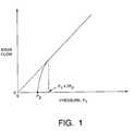
- the relationship between mass flow of a fluid and the fluid pressure upstream of a flow restrictive deviceis linear above a certain critical pressure and nonlinear below that critical pressure. More specifically, when the upstream pressure P 1 is at least twice as great as the downstream pressure P 2 (i.e., P 1 /P 2 ⁇ 2,) the flow is said to be choked, and the flow rate is a function only of P 1 ⁇ 1 and the cross-sectional area A of the flow restrictive aperture.
- choked flowis typically established by maintaining the upstream fluid supply at a pressure that is always at least about twice that of the fluid in the downstream processing chamber. In a choked flow regime, as the pressure of the fluid in the upstream reservoir increases, the density and flow rate of the fluid also increase.
- this relationship between flow rate and upstream pressureis linear so long as the upstream pressure remains at least twice that of the downstream pressure.
- the upstream pressureis less than twice the downstream pressure (i.e., P 1 /P 2 ⁇ 2,)
- the flowis said to be unchoked and the relationship between mass flow rate and downstream fluid pressure is nonlinear.
- the pressure at which a precursor fluid (typically a gas) in the upstream reservoir of a choked flow system is maintainedis, in part, a function of the vapor pressure of the precursor (liquid or solid) from which the gas is derived and the desired quantity of precursor to be delivered.
- a precursor fluidtypically a gas
- Some precursors, typically liquids, used in vapor deposition processeshave vapor pressures which are sufficiently high to ensure their delivery at a pressure which establishes choked flow and thus allows accurate measurement of mass flow.
- Other precursors, particularly low vapor pressure liquids and non-dissolved solids which must be sublimed to provide reactants in gaseous formtypically cannot be delivered at a sufficiently high pressure to ensure choked flow. As a result, the mass flow rate of such precursors cannot be accurately or reliably determined.
- the controllerincludes a flow restrictive element in the precursor flow path, and the pressures of the fluid upstream and downstream of the flow restrictive element are measured. The ratio of the upstream and downstream fluid pressures is computed to determine whether the flow is choked or non-choked.
- the mass flow of the precursor fluidis then computed by a CPU in accordance with a linear function of the upstream pressure, for choked flow, and in accordance with a nonlinear function of both the upstream and downstream pressures, for non-choked flow. Frequent re-calibration of the mass flow controller is not needed.
- the present disclosureprovides a pressure based mass flow controller for controlling the flow rate of a vapor from a source.
- a controllercan be used, for example, in the semiconductor manufacturing industry to precisely deliver a process vapor to a process chamber for making a semiconductor wafer.
- the disclosed flow controllercan be used with a low vapor pressure source, and has a simplified, novel design, that allows the disclosed flow controller to be easily and inexpensively incorporated in a system including a plurality of mass flow controllers and a plurality of vapor sources.
- the flow controllerincludes a flow path for connection to a vapor source, a flow restrictor dividing the flow path into an upstream reservoir and a downstream reservoir, an upstream pressure measurement device connected to the upstream reservoir, and a flow valve connected to the flow path before the upstream reservoir.
- the flow controlleralso includes a control device programmed to receive a predetermined desired flow rate, receive an indication of upstream pressure from the upstream pressure measurement device, and receive an indication of downstream pressure from a remote downstream pressure measurement device connected to the downstream reservoir.
- the control deviceis also programmed to determine an actual mass flow rate of vapor through the flow path during choked flow conditions in accordance with a linear function of the upstream pressure, and determine the actual mass flow rate of the vapor through the flow path during non-choked flow conditions in accordance with a nonlinear function of the upstream pressure and the downstream pressure.
- the control deviceis also programmed to instruct the flow valve to increase flow if the actual flow rate is less than the desired flow rate, and to decrease flow if the actual flow rate is greater than the desired flow rate.
- the present disclosurealso provides a system for controlling the flow rates of vapors derived from a plurality of sources.
- the systemincludes a mass flow controller as described above for each of the plurality of sources.
- the systemfurther includes a manifold connecting the downstream reservoirs of the mass flow controllers, and a downstream pressure measurement device connected to the manifold for providing an indication of the downstream pressure to the control devices of the flow controllers.
- the systemincludes a flow path for connection to each of the plurality of vapor sources, flow restrictors dividing each of the flow paths into an upstream reservoir and a downstream reservoir, and upstream pressure measurement devices connected to each of the upstream reservoirs.
- a manifoldconnects the downstream reservoirs of the mass flow controllers, and a downstream pressure measurement device connected to the manifold.
- the systemalso includes a control device programmed to, for each flow path, receive an indication of upstream pressure from the upstream pressure measurement device of the flow path, and receive an indication of downstream pressure from the downstream pressure measurement device.
- the control devicedetermines an actual mass flow rate of vapor through the flow path in accordance with a linear function of the upstream pressure during choked flow conditions, and determines the actual mass flow rate of the vapor through the flow path in accordance with a nonlinear function of the upstream pressure and the downstream pressure during choked flow conditions.
- FIG. 1is a graph illustrating the relationship of mass flow and the pressure drop of a fluid across a flow restrictive element defining an upstream and downstream reservoir. The graph illustrates both choked and non-choked flow conditions;
- FIG. 2is a simplified schematic diagram of a pressure-based mass flow controller according to the present disclosure
- FIG. 3is a simplified schematic diagram of a system according to the present disclosure, including a plurality of the pressure-based mass flow controllers of FIG. 2;
- FIG. 4is a simplified schematic diagram of another pressure-based mass flow controller system according to the present disclosure.
- the present disclosureprovides a pressure-based mass flow controller (MFC) 10 for controlling the flow rate of a vapor from a source.
- MFCmass flow controller
- Such a controller 10can be used, for example, in the semiconductor manufacturing industry to precisely deliver a process vapor to a process chamber for making a semiconductor wafer.
- the disclosed MFC 10can be used with a low vapor pressure source, and has a simplified, novel design, that allows the disclosed flow controller 10 to be easily and inexpensively incorporated in a system including a plurality of mass flow controllers and a plurality of vapor sources.
- the MFC 10includes a flow path 12 for connection to a vapor source, a flow restrictor 14 dividing the flow path into an upstream reservoir 16 and a downstream reservoir 18 , an upstream pressure measurement device 20 connected to the upstream reservoir, and a flow valve 22 connected to the flow path before the upstream reservoir.
- the MFC 10also includes a control device 24 programmed to receive a predetermined desired flow rate, receive an indication of upstream pressure from the upstream pressure measurement device 20 (as indicated by control circuitry 26 ), and receive an indication of downstream pressure from a remote downstream pressure measurement device (not shown) connected to the downstream reservoir 18 .
- the control device 24is also programmed to determine an actual mass flow rate of vapor through the flow path 12 during choked flow conditions in accordance with a linear function of the upstream pressure, and determine the actual mass flow rate of the vapor through the flow path 12 during non-choked flow conditions in accordance with a nonlinear function of the upstream pressure and the downstream pressure.
- the control device 24is programmed to instruct the flow valve 22 (as indicated by control circuitry 28 ) to increase flow if the actual flow rate is less than the desired flow rate, and to decrease flow if the actual flow rate is greater than the desired flow rate.
- the size of an aperture in the flow restrictor 14is initially determined by the fluid pressures at the inlet and the outlet of the MFC 10 , and clearly can be adjusted from the initial values.
- control device 24it is meant herein a device or mechanism used to regulate or guide the operation of the MFC 10 .
- the control device 24preferably comprises a computer processing unit (CPU) including a processor and memory.
- CPUcomputer processing unit
- the control device 24operates in a feedback loop to maintain the desired flow at all times.
- Equations performed by the control device 24 for computing the mass flow rate from the measured reservoir pressures during both choked flow and non-choked flow conditionsare disclosed in U.S. Pat. No. 5,868,159, which is assigned to the assignee of the present disclosure and incorporated herein by reference.
- the control device 24stores user input parameters necessary for carrying out the calculations.
- the cross-sectional diameter of the aperture in the flow restrictor 14is typically input by a user and, indirectly, the discharge coefficient of the flow restrictor.
- Values of the molecular weight, the universal gas constant, and the specific heat ration for several precursor gasesmay be input or previously stored in the control device.
- the parameters as well as a desired flow ratecan be entered into the control device 24 through a user input device (not shown), such as a keyboard and monitor for example, via an analog set point.
- the determination by the control device 24 of the mass flow ratealso forms the basis of a feedback loop for adjusting the flow valve 22 in response to changes in fluid pressure within the upstream reservoir and/or the downstream reservoir to ensure that the actual flow rate is the same as the input desired flow rate.
- Information on flow rate as a function of the flow valve control currentis preferably stored in the control device 24 in order to quicken the response time of the MFC 10 .
- the pressure measurement device 20can be any type of pressure transducer capable of measuring fluid pressures within the range of interest.
- the pressure measurement devicecan include an absolute pressure transducer 20 .
- Preferred pressure measurement devicescomprise Baratron® capacitance manometers available from MKS Instruments, Inc. of Andover, Mass. (www.mksinst.com).
- the flow, or control, valve 22may be any kind of valve for controlling the flow of fluid through the flow path 12 in response to a control signal provided from the control device 24 .
- the flow valve 22 and the control device 24accommodate all flow rates from a complete shut off position (providing zero flow) to a complete open position (providing maximum flow), including flow rates required for choked as well as non-choked flow, although under certain applications it may be desirable to design the controller for only one flow regime.
- the specific characteristics of the flow valve 22will depend on the expected delivery pressure range of the precursor material and the dimensions of the flow path 12 and the flow restrictor 14 , and can be, for example, as a solenoid valve, a throttle valve or a flapper valve.
- a preferred valveis a proportioning solenoid control valve 22 .
- the flow path 12is maintained at a constant, desired temperature preferably by surrounding the flow path with temperature control means, including thermal insulating means, a heater 30 , and one or more temperature sensors 32 for sensing the temperature(s) along the flow path and for operating the heater in a feedback arrangement so as to maintain the temperature of the flow path at a predetermined fixed temperature.
- the control device 24employs feedback control loops for accurately controlling the temperature of the fluid (and for maintaining the temperature of the flow path 12 at a desired temperature) in response to changes in fluid flow. Signals sent from the temperature sensors 32 to the control device (as indicated by control circuitry 34 ) operate to controllably adjust the heater 30 (as indicated by control circuitry 36 ) and, thus, the temperature of the vapor in the flow path 12 .
- a predetermined temperature set point or rangecan be programmed into the control device 24 to ensure that the fluid is maintained at the desired temperature or range.
- the pressure-based MFC 10 of the present disclosurecan be used to deliver gaseous reactants from liquid and non-dissolved solid precursors characterized by a wide range of vapor pressures at the delivery temperatures.
- the pressure-based MFC 10 of the present disclosuremay be used to monitor and control the delivery of vapors to a process, or reaction, chamber in a variety of industrial applications, including the manufacture of semiconductor devices using precursor materials having relatively low vapor pressures.
- precursor materialsinclude liquid precursors having low vapor pressures and solid precursors which sublime, i.e., enter the gaseous state directly from the solid state.
- the solid precursor materialsmay be melted at an appropriate temperature and the mass flow of the gaseous reactants derived therefrom may be determined using the MFC 10 of the present disclosure, without the use of a solvent.
- the pressure-based MFC 10 of the present disclosureis particularly suitable for use in systems that require delivery of gaseous reactants of high purity to a processing chamber.
- the pressure-based MFC 10 of the present disclosureeffectively and more reliably models the relationship between upstream fluid pressure and mass flow rate, since it is capable of determining and controlling mass flow rate with high accuracy and fast response time over a wide range of flow rates in both the choked and non-choked flow regimes for a wide variety of precursor fluids.
- the pressure-based MFC 10 of the present disclosureincludes the versatility of the unit.
- a single MFC 10 according to the disclosurecan be used in applications in which, formerly, several MFCs, each calibrated for a particular gas, temperature, pressure and/or a particular flow rate range, were required.
- the MFC 10can be used to control the flow rate of a vapor derived from a precursor characterized by a vapor pressure ranging as low as 2 torr or lower, to at least 760 torr or higher, at temperatures of up to at least 250° C. or higher.
- the pressure transducer 20 , heating element 30 , CPU 24 , valve 22 and controlling circuitry which comprise the MFC 10are provided in a relatively compact, integral unit.
- the calibration and computationsare performed in-line by the CPU 24 .
- the feedback control loopsare digitally controlled for improved accuracy and response time; however, both analog and digital operation are permitted.
- the on-board calibration feature of the present disclosureprovides additional accuracy and reliability, as calibration of the MFC 10 can be done at multiple increments of full scale readings instead of merely at 0 and 100 percent full scale.
- calibration of the individual components, namely, the pressure transducer 20is not required.
- the system 50 of FIG. 3includes a mass flow controller 10 according to FIG. 2 for each of the plurality of sources.
- the system 50further includes a manifold 52 connecting the downstream reservoirs 18 of the MFCs 10 , and a downstream pressure measurement device 54 connected to the manifold 52 for providing an indication of the downstream pressure to the control devices 24 of the MFCs (as indicated by control circuitry 56 ).
- the pressure measurement device 54can comprise an absolute pressure transducer, and preferably comprises a Baratron® capacitance manometer.
- the system 50also includes inlet valves 58 for connecting the upstream reservoirs 16 of the MFCs 10 to their respective sources of vapor, and outlet valves 60 connecting the downstream reservoirs 18 of the MFCs to the manifold 52 , whereby at least one of the mass flow controllers 10 can be made to communicate with the manifold 52 .
- a valve 62is also provided for connecting the manifold 52 to the process chamber.
- the system 50can additionally include temperature measurement devices 64 connected to the manifold 52 , a heater 66 for heating the manifold, and a control device 68 (i.e., CPU) for maintaining the manifold at a constant, desired temperature, similar to the temperature control system of each MFC 10 .
- the control device 68is programmed to receive a desired vapor temperature from a user input device, and receive an indication of actual vapor temperature within the manifold 52 from the temperature measurement devices 64 (as indicated by control circuitry 70 ).
- the control device 68then instructs the heater 66 (as indicated by control circuitry 72 ) to increase heat to the manifold 52 if the actual vapor temperature within the manifold is less than the desired vapor temperature, and instruct the heater to decrease heat to the manifold if the actual vapor temperature within the manifold is greater than the desired vapor temperature.
- a single temperature control systemcan be provided for the mass flow controller system 50 in place of the separate systems for each MFC 10 and the system for the manifold 52 .
- FIG. 4another mass flow controller system 80 according to the present disclosure is shown.
- the system 80 of FIG. 4is similar to the system 50 of FIG. 3, and elements that are the same have the same reference numerals.
- the system 80includes a mass flow controller 110 for each of the plurality of vapor sources.
- the MFCs 110 of FIG. 4are similar to the MFCs 10 of FIG. 3 except that the MFCs 110 are not provided with their own CPUs. Instead the system 80 is provided with a single control device (i.e., CPU) 82 connected to each of the MFCs 110 (as indicated by control circuitry 84 ) and connected to downstream pressure measurement device 54 (as indicated by control circuitry 86 ) of the manifold 52 .
- the control device 82controls the flow valves 22 of each MFC 110 based upon upstream and downstream pressure readings provided by the upstream pressure measurement devices 20 of the MFCs 110 and the downstream pressure measurement device 54 of the manifold 52 .
- the control device 82is also preferably connected to the temperature measurement devices 64 and the heater 66 (as indicated by control circuitry 88 , 90 ) of the manifold 52 , for maintaining the manifold at a constant, desired temperature.
Landscapes
- Engineering & Computer Science (AREA)
- Physics & Mathematics (AREA)
- General Physics & Mathematics (AREA)
- Automation & Control Theory (AREA)
- Condensed Matter Physics & Semiconductors (AREA)
- Manufacturing & Machinery (AREA)
- Computer Hardware Design (AREA)
- Microelectronics & Electronic Packaging (AREA)
- Power Engineering (AREA)
- Flow Control (AREA)
Abstract
Description
Claims (16)
Priority Applications (6)
| Application Number | Priority Date | Filing Date | Title |
|---|---|---|---|
| US09/748,472US6631334B2 (en) | 2000-12-26 | 2000-12-26 | Pressure-based mass flow controller system |
| GB0312001AGB2386704B (en) | 2000-12-26 | 2001-08-06 | Pressure-based mass flow controller system |
| PCT/US2001/024608WO2002052363A1 (en) | 2000-12-26 | 2001-08-06 | Pressure-based mass flow controller system |
| KR10-2003-7008071AKR20030074663A (en) | 2000-12-26 | 2001-08-06 | Pressure-based mass flow controller system |
| JP2002553600AJP2004517396A (en) | 2000-12-26 | 2001-08-06 | Pressure type mass flow controller system |
| DE10196953TDE10196953T1 (en) | 2000-12-26 | 2001-08-06 | Pressure based mass flow control system |
Applications Claiming Priority (1)
| Application Number | Priority Date | Filing Date | Title |
|---|---|---|---|
| US09/748,472US6631334B2 (en) | 2000-12-26 | 2000-12-26 | Pressure-based mass flow controller system |
Publications (2)
| Publication Number | Publication Date |
|---|---|
| US20020082783A1 US20020082783A1 (en) | 2002-06-27 |
| US6631334B2true US6631334B2 (en) | 2003-10-07 |
Family
ID=25009590
Family Applications (1)
| Application Number | Title | Priority Date | Filing Date |
|---|---|---|---|
| US09/748,472Expired - LifetimeUS6631334B2 (en) | 2000-12-26 | 2000-12-26 | Pressure-based mass flow controller system |
Country Status (6)
| Country | Link |
|---|---|
| US (1) | US6631334B2 (en) |
| JP (1) | JP2004517396A (en) |
| KR (1) | KR20030074663A (en) |
| DE (1) | DE10196953T1 (en) |
| GB (1) | GB2386704B (en) |
| WO (1) | WO2002052363A1 (en) |
Cited By (34)
| Publication number | Priority date | Publication date | Assignee | Title |
|---|---|---|---|---|
| US20040074311A1 (en)* | 2002-07-19 | 2004-04-22 | Celerity Group, Inc. | Methods and apparatus for pressure compensation in a mass flow controller |
| US6752166B2 (en)* | 2001-05-24 | 2004-06-22 | Celerity Group, Inc. | Method and apparatus for providing a determined ratio of process fluids |
| US20050029369A1 (en)* | 2003-06-09 | 2005-02-10 | Hideki Nagaoka | Partial pressure control system, flow rate control system and shower plate used for partial pressure control system |
| US20050098906A1 (en)* | 2003-08-28 | 2005-05-12 | Asm Japan K.K. | Source gas flow control and CVD using same |
| US6909973B2 (en)* | 2003-03-28 | 2005-06-21 | Advanced Technology Materials, Inc. | Photometrically modulated delivery of reagents |
| US20050167627A1 (en)* | 2001-04-24 | 2005-08-04 | Lull John M. | System and method for a mass flow controller |
| US20050223979A1 (en)* | 2004-04-12 | 2005-10-13 | Ali Shajii | Pulsed mass flow delivery system and method |
| US20050246107A1 (en)* | 2003-03-28 | 2005-11-03 | Arno Jose I | Photometrically modulated delivery of reagents |
| US20050288825A1 (en)* | 2004-07-08 | 2005-12-29 | Tinsley Kenneth E | Method and system for a mass flow controller with reduced pressure sensitivity |
| US20060097644A1 (en)* | 2003-06-09 | 2006-05-11 | Ckd Corporation | Relative pressure control system and relative flow control system |
| US20070181703A1 (en)* | 2006-02-07 | 2007-08-09 | Daryl Buchanan | System and method for producing and delivering vapor |
| US20090059717A1 (en)* | 2007-08-31 | 2009-03-05 | Ckd Corporation | Fluid mixing system and fluid mixing apparatus |
| US7628861B2 (en)* | 2004-12-17 | 2009-12-08 | Mks Instruments, Inc. | Pulsed mass flow delivery system and method |
| US20100224264A1 (en)* | 2005-06-22 | 2010-09-09 | Advanced Technology Materials, Inc. | Apparatus and process for integrated gas blending |
| US20100229657A1 (en)* | 2009-03-12 | 2010-09-16 | Weinstein Jason P | Sinter-bonded metal flow restrictor for regulating volumetric gas flow through an aerosol sampler inlet |
| US20120073672A1 (en)* | 2010-09-29 | 2012-03-29 | Junhua Ding | System for and method of fast pulse gas delivery |
| US8727323B2 (en) | 2006-10-17 | 2014-05-20 | Mks Instruments, Inc. | Devices, systems, and methods for carbonation of deionized water |
| WO2014152755A2 (en) | 2013-03-14 | 2014-09-25 | Christopher Max Horwitz | Pressure-based gas flow controller with dynamic self-calibration |
| US20140295083A1 (en)* | 2013-03-29 | 2014-10-02 | Tokyo Electron Limited | Film forming apparatus, gas supply device and film forming method |
| US9348339B2 (en) | 2010-09-29 | 2016-05-24 | Mks Instruments, Inc. | Method and apparatus for multiple-channel pulse gas delivery system |
| US9958302B2 (en) | 2011-08-20 | 2018-05-01 | Reno Technologies, Inc. | Flow control system, method, and apparatus |
| US10031531B2 (en) | 2011-02-25 | 2018-07-24 | Mks Instruments, Inc. | System for and method of multiple channel fast pulse gas delivery |
| US10126760B2 (en) | 2011-02-25 | 2018-11-13 | Mks Instruments, Inc. | System for and method of fast pulse gas delivery |
| US10303189B2 (en) | 2016-06-30 | 2019-05-28 | Reno Technologies, Inc. | Flow control system, method, and apparatus |
| US10353408B2 (en) | 2011-02-25 | 2019-07-16 | Mks Instruments, Inc. | System for and method of fast pulse gas delivery |
| US10663337B2 (en) | 2016-12-30 | 2020-05-26 | Ichor Systems, Inc. | Apparatus for controlling flow and method of calibrating same |
| US10679880B2 (en) | 2016-09-27 | 2020-06-09 | Ichor Systems, Inc. | Method of achieving improved transient response in apparatus for controlling flow and system for accomplishing same |
| US10698426B2 (en) | 2018-05-07 | 2020-06-30 | Mks Instruments, Inc. | Methods and apparatus for multiple channel mass flow and ratio control systems |
| US10838437B2 (en) | 2018-02-22 | 2020-11-17 | Ichor Systems, Inc. | Apparatus for splitting flow of process gas and method of operating same |
| US11003198B2 (en) | 2011-08-20 | 2021-05-11 | Ichor Systems, Inc. | Controlled delivery of process gas using a remote pressure measurement device |
| US11144075B2 (en) | 2016-06-30 | 2021-10-12 | Ichor Systems, Inc. | Flow control system, method, and apparatus |
| US11231313B2 (en)* | 2017-04-18 | 2022-01-25 | Tokyo Electron Limited | Method of obtaining output flow rate of flow rate controller and method of processing workpiece |
| US11899477B2 (en) | 2021-03-03 | 2024-02-13 | Ichor Systems, Inc. | Fluid flow control system comprising a manifold assembly |
| US12000723B2 (en) | 2022-02-18 | 2024-06-04 | Mks Instruments, Inc. | Method and apparatus for pressure based mass flow control |
Families Citing this family (20)
| Publication number | Priority date | Publication date | Assignee | Title |
|---|---|---|---|---|
| US6962090B2 (en)* | 2002-02-28 | 2005-11-08 | Avl North America Inc. | Heated stainless steel emissions canister |
| GB2392506A (en)* | 2002-07-23 | 2004-03-03 | Alan Paul Troup | A mass flow meter and controller therefor |
| US20060060139A1 (en)* | 2004-04-12 | 2006-03-23 | Mks Instruments, Inc. | Precursor gas delivery with carrier gas mixing |
| US20060130755A1 (en)* | 2004-12-17 | 2006-06-22 | Clark William R | Pulsed mass flow measurement system and method |
| US7706925B2 (en)* | 2007-01-10 | 2010-04-27 | Mks Instruments, Inc. | Integrated pressure and flow ratio control system |
| US20080305014A1 (en)* | 2007-06-07 | 2008-12-11 | Hitachi Kokusai Electric Inc. | Substrate processing apparatus |
| US8712665B2 (en)* | 2009-11-30 | 2014-04-29 | General Electric Company | Systems and methods for unchoked control of gas turbine fuel gas control valves |
| KR102111702B1 (en)* | 2011-04-07 | 2020-05-15 | 피코순 오와이 | Atomic layer deposition with plasma source |
| NL2009660C2 (en)* | 2012-10-18 | 2014-04-22 | Avantium Technologies B V | Pressure controller. |
| WO2015012702A1 (en)* | 2013-07-24 | 2015-01-29 | Ikm Production Technology As | Measurement device |
| WO2017040100A1 (en) | 2015-08-31 | 2017-03-09 | Mks Instruments, Inc. | Method and apparatus for pressure-based flow measurement in non-critical flow conditions |
| US10684159B2 (en)* | 2016-06-27 | 2020-06-16 | Applied Materials, Inc. | Methods, systems, and apparatus for mass flow verification based on choked flow |
| US9890908B1 (en)* | 2017-04-18 | 2018-02-13 | Air Products And Chemicals, Inc. | Control system in a gas pipeline network to increase capacity factor |
| CN107894024B (en)* | 2017-11-22 | 2023-08-18 | 新奥泛能网络科技股份有限公司 | Control method and system of multi-source heating power pipe network |
| JP7524068B2 (en)* | 2018-04-03 | 2024-07-29 | ラム リサーチ コーポレーション | MEMS Coriolis Gas Flow Controller |
| US10705543B2 (en)* | 2018-08-29 | 2020-07-07 | Illinois Tool Works, Inc. | Mass flow controller and controller algorithm |
| KR20250073548A (en)* | 2021-08-13 | 2025-05-27 | 티에스아이 인코포레이티드 | Differential pressure liquid flow controller |
| JP7752036B2 (en)* | 2021-11-30 | 2025-10-09 | 株式会社堀場エステック | Flow rate control device, flow rate control method, and program for flow rate control device |
| US20230369072A1 (en)* | 2022-05-13 | 2023-11-16 | Applied Materials, Inc. | Systems and methods to reduce flow accuracy error for liquid & gas mass flow controller devices |
| US20240281007A1 (en)* | 2023-02-17 | 2024-08-22 | Mks Instruments, Inc. | Method and Apparatus for Integrated Pressure and Flow Controller |
Citations (10)
| Publication number | Priority date | Publication date | Assignee | Title |
|---|---|---|---|---|
| US3851526A (en) | 1973-04-09 | 1974-12-03 | Tylan Corp | Fluid flowmeter |
| US4951224A (en) | 1987-07-30 | 1990-08-21 | Jiri Hokynar | Control device for fluid flow |
| US5427149A (en)* | 1989-12-18 | 1995-06-27 | Higgs; Robert E. | Flow metering injection controller |
| US5445035A (en) | 1991-12-18 | 1995-08-29 | Delajoud; Pierre R. | Precision gas mass flow measurement apparatus and method maintaining constant fluid temperature in thin elongated flow path |
| US5791369A (en) | 1995-06-12 | 1998-08-11 | Fujikin Incorporated | Pressure type flow rate control apparatus |
| US5868159A (en)* | 1996-07-12 | 1999-02-09 | Mks Instruments, Inc. | Pressure-based mass flow controller |
| EP0969342A1 (en) | 1998-01-21 | 2000-01-05 | Fujikin Inc. | Fluid supply apparatus |
| US6074691A (en) | 1997-06-24 | 2000-06-13 | Balzers Aktiengesellschaft | Method for monitoring the flow of a gas into a vacuum reactor |
| US6296711B1 (en)* | 1998-04-14 | 2001-10-02 | Cvd Systems, Inc. | Film processing system |
| US20010035127A1 (en)* | 1998-10-27 | 2001-11-01 | Craig R. Metzner | Deposition reactor having vaporizing, mixing and cleaning capabilities |
- 2000
- 2000-12-26USUS09/748,472patent/US6631334B2/ennot_activeExpired - Lifetime
- 2001
- 2001-08-06KRKR10-2003-7008071Apatent/KR20030074663A/ennot_activeCeased
- 2001-08-06DEDE10196953Tpatent/DE10196953T1/ennot_activeWithdrawn
- 2001-08-06GBGB0312001Apatent/GB2386704B/ennot_activeExpired - Fee Related
- 2001-08-06JPJP2002553600Apatent/JP2004517396A/enactivePending
- 2001-08-06WOPCT/US2001/024608patent/WO2002052363A1/enactiveApplication Filing
Patent Citations (10)
| Publication number | Priority date | Publication date | Assignee | Title |
|---|---|---|---|---|
| US3851526A (en) | 1973-04-09 | 1974-12-03 | Tylan Corp | Fluid flowmeter |
| US4951224A (en) | 1987-07-30 | 1990-08-21 | Jiri Hokynar | Control device for fluid flow |
| US5427149A (en)* | 1989-12-18 | 1995-06-27 | Higgs; Robert E. | Flow metering injection controller |
| US5445035A (en) | 1991-12-18 | 1995-08-29 | Delajoud; Pierre R. | Precision gas mass flow measurement apparatus and method maintaining constant fluid temperature in thin elongated flow path |
| US5791369A (en) | 1995-06-12 | 1998-08-11 | Fujikin Incorporated | Pressure type flow rate control apparatus |
| US5868159A (en)* | 1996-07-12 | 1999-02-09 | Mks Instruments, Inc. | Pressure-based mass flow controller |
| US6074691A (en) | 1997-06-24 | 2000-06-13 | Balzers Aktiengesellschaft | Method for monitoring the flow of a gas into a vacuum reactor |
| EP0969342A1 (en) | 1998-01-21 | 2000-01-05 | Fujikin Inc. | Fluid supply apparatus |
| US6296711B1 (en)* | 1998-04-14 | 2001-10-02 | Cvd Systems, Inc. | Film processing system |
| US20010035127A1 (en)* | 1998-10-27 | 2001-11-01 | Craig R. Metzner | Deposition reactor having vaporizing, mixing and cleaning capabilities |
Non-Patent Citations (4)
| Title |
|---|
| MKS Instruments, Low Vapor Pressure Source Mass Flow Controller Type 1153, Feb. 1998, MKS Instruments, Inc. Bulletin 1153-2/98. |
| MKS Instruments, Pressure-Based Mass-Flo Controller For Ion Implant Applications Type 1640, 04/00, MKS Instruments, Inc. Bulletin 1640-4/00. |
| MKS Instruments, Vapor Source Mass-Flo Controllers Types 1150C &1152C, 02/99, MKS Instruments, Inc. Bulletin 1150/2-2/99. |
| MKS Instruments, Vapor/Liquid Flow Controller Options, 12/99, MKS Instruments, Inc. Bulletin Vapor/Liquid Spec-12/99. |
Cited By (84)
| Publication number | Priority date | Publication date | Assignee | Title |
|---|---|---|---|---|
| US7114511B2 (en) | 2001-04-24 | 2006-10-03 | Celerity Group, Inc. | System and method for a mass flow controller |
| US7231931B2 (en) | 2001-04-24 | 2007-06-19 | Celerity, Inc. | System and method for a mass flow controller |
| US20050167627A1 (en)* | 2001-04-24 | 2005-08-04 | Lull John M. | System and method for a mass flow controller |
| US7380564B2 (en) | 2001-04-24 | 2008-06-03 | Celerity, Inc. | System and method for a mass flow controller |
| US6962164B2 (en) | 2001-04-24 | 2005-11-08 | Celerity Group, Inc. | System and method for a mass flow controller |
| US6752166B2 (en)* | 2001-05-24 | 2004-06-22 | Celerity Group, Inc. | Method and apparatus for providing a determined ratio of process fluids |
| US20040200529A1 (en)* | 2001-05-24 | 2004-10-14 | Celerity Group, Inc. | Method and apparatus for providing a determined ratio of process fluids |
| US7143774B2 (en) | 2001-05-24 | 2006-12-05 | Celerity, Inc. | Method and apparatus for providing a determined ratio of process fluids |
| US20070107783A1 (en)* | 2001-05-24 | 2007-05-17 | Lull John M | Method and apparatus for providing a determined ratio of process fluids |
| US6941965B2 (en) | 2001-05-24 | 2005-09-13 | Celerity, Inc. | Method and apparatus for providing a determined ratio of process fluids |
| US7424894B2 (en) | 2001-05-24 | 2008-09-16 | Celerity, Inc. | Method and apparatus for providing a determined ratio of process fluids |
| US7360551B2 (en) | 2001-05-24 | 2008-04-22 | Celerity, Inc. | Method and apparatus for providing a determined ratio of process fluids |
| US20050241698A1 (en)* | 2001-05-24 | 2005-11-03 | Lull John M | Method and apparatus for providing a determined ratio of process fluids |
| US7434477B2 (en) | 2002-07-19 | 2008-10-14 | Celerity, Inc. | Methods and apparatus for pressure compensation in a mass flow controller |
| US20070288180A1 (en)* | 2002-07-19 | 2007-12-13 | Celerity, Inc. | Methods and apparatus for pressure compensation in a mass flow controller |
| US7273063B2 (en) | 2002-07-19 | 2007-09-25 | Celerity, Inc. | Methods and apparatus for pressure compensation in a mass flow controller |
| US7073392B2 (en) | 2002-07-19 | 2006-07-11 | Celerity, Inc. | Methods and apparatus for pressure compensation in a mass flow controller |
| US8751180B2 (en) | 2002-07-19 | 2014-06-10 | Brooks Instrument Llc | Methods and apparatus for pressure compensation in a mass flow controller |
| US20050223813A1 (en)* | 2002-07-19 | 2005-10-13 | Celerity Group, Inc. | Methods and apparatus for pressure compensation in a mass flow controller |
| US20090078055A1 (en)* | 2002-07-19 | 2009-03-26 | Celerity, Inc. | Methods and apparatus for pressure compensation in a mass flow controller |
| US20040074311A1 (en)* | 2002-07-19 | 2004-04-22 | Celerity Group, Inc. | Methods and apparatus for pressure compensation in a mass flow controller |
| US20080213925A1 (en)* | 2003-03-28 | 2008-09-04 | Advanced Technology Materials, Inc. | Photometrically modulated delivery of reagents |
| US20100217415A1 (en)* | 2003-03-28 | 2010-08-26 | Advanced Technology Materials, Inc. | Photometrically modulated delivery of reagents |
| US7925450B2 (en) | 2003-03-28 | 2011-04-12 | Advanced Technology Materials, Inc. | Photometrically modulated delivery of reagents |
| US20060237061A1 (en)* | 2003-03-28 | 2006-10-26 | Arno Jose I | In-situ gas blending and dilution system for delivery of dilute gas at a predetermined concentration |
| US20060217896A1 (en)* | 2003-03-28 | 2006-09-28 | Advanced Technology Materials, Inc. | Photometrically modulated delivery of reagents |
| US7058519B2 (en) | 2003-03-28 | 2006-06-06 | Advanced Technology Materials, Inc. | Photometrically modulated delivery of reagents |
| US8244482B2 (en) | 2003-03-28 | 2012-08-14 | Advanced Technology Materials, Inc. | Photometrically modulated delivery of reagents |
| US7325560B2 (en) | 2003-03-28 | 2008-02-05 | Advanced Technology Materials, Inc. | In-situ gas blending and dilution system for delivery of dilute gas at a predetermined concentration |
| US6909973B2 (en)* | 2003-03-28 | 2005-06-21 | Advanced Technology Materials, Inc. | Photometrically modulated delivery of reagents |
| US7711496B2 (en) | 2003-03-28 | 2010-05-04 | Advanced Technology Materials, Inc. | Photometrically modulated delivery of reagents |
| US7373257B2 (en) | 2003-03-28 | 2008-05-13 | Advanced Technology Materials, Inc. | Photometrically modulated delivery of reagents |
| US20050246107A1 (en)* | 2003-03-28 | 2005-11-03 | Arno Jose I | Photometrically modulated delivery of reagents |
| US20050029369A1 (en)* | 2003-06-09 | 2005-02-10 | Hideki Nagaoka | Partial pressure control system, flow rate control system and shower plate used for partial pressure control system |
| US8109288B2 (en) | 2003-06-09 | 2012-02-07 | Tokyo Electron Limited | Flow rate control system and shower plate used for partial pressure control system |
| US7353841B2 (en)* | 2003-06-09 | 2008-04-08 | Ckd Corporation | Relative pressure control system and relative flow control system |
| US20080300728A1 (en)* | 2003-06-09 | 2008-12-04 | Tokyo Electron Limited | Flow rate control system and shower plate used for partial pressure control system |
| US7481240B2 (en)* | 2003-06-09 | 2009-01-27 | Tokyo Electron Limited | Partial pressure control system, flow rate control system and shower plate used for partial pressure control system |
| US20060097644A1 (en)* | 2003-06-09 | 2006-05-11 | Ckd Corporation | Relative pressure control system and relative flow control system |
| US20050098906A1 (en)* | 2003-08-28 | 2005-05-12 | Asm Japan K.K. | Source gas flow control and CVD using same |
| US20050223979A1 (en)* | 2004-04-12 | 2005-10-13 | Ali Shajii | Pulsed mass flow delivery system and method |
| US7628860B2 (en)* | 2004-04-12 | 2009-12-08 | Mks Instruments, Inc. | Pulsed mass flow delivery system and method |
| US7615120B2 (en)* | 2004-04-12 | 2009-11-10 | Mks Instruments, Inc. | Pulsed mass flow delivery system and method |
| US7829353B2 (en) | 2004-04-12 | 2010-11-09 | Mks Instruments, Inc. | Pulsed mass flow delivery system and method |
| US20070039549A1 (en)* | 2004-04-12 | 2007-02-22 | Mks Instruments, Inc. | Pulsed mass flow delivery system and method |
| US7216019B2 (en) | 2004-07-08 | 2007-05-08 | Celerity, Inc. | Method and system for a mass flow controller with reduced pressure sensitivity |
| US20050288825A1 (en)* | 2004-07-08 | 2005-12-29 | Tinsley Kenneth E | Method and system for a mass flow controller with reduced pressure sensitivity |
| US7628861B2 (en)* | 2004-12-17 | 2009-12-08 | Mks Instruments, Inc. | Pulsed mass flow delivery system and method |
| US20100224264A1 (en)* | 2005-06-22 | 2010-09-09 | Advanced Technology Materials, Inc. | Apparatus and process for integrated gas blending |
| US9666435B2 (en) | 2005-06-22 | 2017-05-30 | Entegris, Inc. | Apparatus and process for integrated gas blending |
| US7680399B2 (en) | 2006-02-07 | 2010-03-16 | Brooks Instrument, Llc | System and method for producing and delivering vapor |
| US20070181703A1 (en)* | 2006-02-07 | 2007-08-09 | Daryl Buchanan | System and method for producing and delivering vapor |
| US8727323B2 (en) | 2006-10-17 | 2014-05-20 | Mks Instruments, Inc. | Devices, systems, and methods for carbonation of deionized water |
| US8201989B2 (en)* | 2007-08-31 | 2012-06-19 | Ckd Corporation | Fluid mixing system and fluid mixing apparatus |
| US20090059717A1 (en)* | 2007-08-31 | 2009-03-05 | Ckd Corporation | Fluid mixing system and fluid mixing apparatus |
| US20100229657A1 (en)* | 2009-03-12 | 2010-09-16 | Weinstein Jason P | Sinter-bonded metal flow restrictor for regulating volumetric gas flow through an aerosol sampler inlet |
| US8997686B2 (en)* | 2010-09-29 | 2015-04-07 | Mks Instruments, Inc. | System for and method of fast pulse gas delivery |
| US9348339B2 (en) | 2010-09-29 | 2016-05-24 | Mks Instruments, Inc. | Method and apparatus for multiple-channel pulse gas delivery system |
| US20120073672A1 (en)* | 2010-09-29 | 2012-03-29 | Junhua Ding | System for and method of fast pulse gas delivery |
| US10031531B2 (en) | 2011-02-25 | 2018-07-24 | Mks Instruments, Inc. | System for and method of multiple channel fast pulse gas delivery |
| US10126760B2 (en) | 2011-02-25 | 2018-11-13 | Mks Instruments, Inc. | System for and method of fast pulse gas delivery |
| US10353408B2 (en) | 2011-02-25 | 2019-07-16 | Mks Instruments, Inc. | System for and method of fast pulse gas delivery |
| US10969799B2 (en) | 2011-02-25 | 2021-04-06 | Mks Instruments, Inc. | System for and method of fast pulse gas delivery |
| US10782165B2 (en) | 2011-08-20 | 2020-09-22 | Ichor Systems, Inc. | Flow control system, method, and apparatus |
| US12228435B2 (en) | 2011-08-20 | 2025-02-18 | Ichor Systems, Inc. | Flow control system, method, and apparatus |
| US9958302B2 (en) | 2011-08-20 | 2018-05-01 | Reno Technologies, Inc. | Flow control system, method, and apparatus |
| US11003198B2 (en) | 2011-08-20 | 2021-05-11 | Ichor Systems, Inc. | Controlled delivery of process gas using a remote pressure measurement device |
| WO2014152755A2 (en) | 2013-03-14 | 2014-09-25 | Christopher Max Horwitz | Pressure-based gas flow controller with dynamic self-calibration |
| US9910448B2 (en) | 2013-03-14 | 2018-03-06 | Christopher Max Horwitz | Pressure-based gas flow controller with dynamic self-calibration |
| US20140295083A1 (en)* | 2013-03-29 | 2014-10-02 | Tokyo Electron Limited | Film forming apparatus, gas supply device and film forming method |
| US9644266B2 (en)* | 2013-03-29 | 2017-05-09 | Tokyo Electron Limited | Film forming apparatus, gas supply device and film forming method |
| US11815920B2 (en) | 2016-06-30 | 2023-11-14 | Ichor Systems, Inc. | Flow control system, method, and apparatus |
| US10782710B2 (en) | 2016-06-30 | 2020-09-22 | Ichor Systems, Inc. | Flow control system, method, and apparatus |
| US10303189B2 (en) | 2016-06-30 | 2019-05-28 | Reno Technologies, Inc. | Flow control system, method, and apparatus |
| US11144075B2 (en) | 2016-06-30 | 2021-10-12 | Ichor Systems, Inc. | Flow control system, method, and apparatus |
| US12411502B2 (en) | 2016-06-30 | 2025-09-09 | Ichor Systems, Inc. | Flow control system, method, and apparatus |
| US11424148B2 (en) | 2016-09-27 | 2022-08-23 | Ichor Systems, Inc. | Method of achieving improved transient response in apparatus for controlling flow and system for accomplishing same |
| US10679880B2 (en) | 2016-09-27 | 2020-06-09 | Ichor Systems, Inc. | Method of achieving improved transient response in apparatus for controlling flow and system for accomplishing same |
| US10663337B2 (en) | 2016-12-30 | 2020-05-26 | Ichor Systems, Inc. | Apparatus for controlling flow and method of calibrating same |
| US11231313B2 (en)* | 2017-04-18 | 2022-01-25 | Tokyo Electron Limited | Method of obtaining output flow rate of flow rate controller and method of processing workpiece |
| US10838437B2 (en) | 2018-02-22 | 2020-11-17 | Ichor Systems, Inc. | Apparatus for splitting flow of process gas and method of operating same |
| US10698426B2 (en) | 2018-05-07 | 2020-06-30 | Mks Instruments, Inc. | Methods and apparatus for multiple channel mass flow and ratio control systems |
| US11899477B2 (en) | 2021-03-03 | 2024-02-13 | Ichor Systems, Inc. | Fluid flow control system comprising a manifold assembly |
| US12000723B2 (en) | 2022-02-18 | 2024-06-04 | Mks Instruments, Inc. | Method and apparatus for pressure based mass flow control |
Also Published As
| Publication number | Publication date |
|---|---|
| WO2002052363A1 (en) | 2002-07-04 |
| DE10196953T1 (en) | 2003-12-11 |
| KR20030074663A (en) | 2003-09-19 |
| US20020082783A1 (en) | 2002-06-27 |
| GB2386704A (en) | 2003-09-24 |
| JP2004517396A (en) | 2004-06-10 |
| GB0312001D0 (en) | 2003-07-02 |
| GB2386704B (en) | 2005-05-11 |
Similar Documents
| Publication | Publication Date | Title |
|---|---|---|
| US6631334B2 (en) | Pressure-based mass flow controller system | |
| US5868159A (en) | Pressure-based mass flow controller | |
| JP4594728B2 (en) | Flow controller based on higher accuracy pressure | |
| US11467608B2 (en) | Systems and methods for flow sensor back pressure adjustment for mass flow controller | |
| KR101391198B1 (en) | Controller gain scheduling for mass flow controllers | |
| US6074691A (en) | Method for monitoring the flow of a gas into a vacuum reactor | |
| US20100145633A1 (en) | Flow controller, flow measuring device testing method, flow controller testing system, and semiconductor manufacturing apparatus | |
| CN101760727A (en) | Material gas concentration control system | |
| EP3791242B1 (en) | Methods and apparatus for multiple channel mass flow and ratio control systems | |
| Liso et al. | A new differential pressure sensor based mass flow controller for advanced semiconductor processing | |
| US6868723B2 (en) | Thermal anemometry mass flow measurement apparatus and method | |
| JPH02268826A (en) | Flow rate control device for evaporated gas | |
| JP3311762B2 (en) | Mass flow controller and semiconductor device manufacturing equipment | |
| WO2025211124A1 (en) | Flow rate measurement device and fluid control device | |
| Saleem | Officer, Brooks Instrument |
Legal Events
| Date | Code | Title | Description |
|---|---|---|---|
| AS | Assignment | Owner name:MKS INSTRUMENTS, INC., MASSACHUSETTS Free format text:ASSIGNMENT OF ASSIGNORS INTEREST;ASSIGNOR:GROSSHART, PAUL FRANCIS;REEL/FRAME:011407/0500 Effective date:20001221 | |
| STCF | Information on status: patent grant | Free format text:PATENTED CASE | |
| FPAY | Fee payment | Year of fee payment:4 | |
| FPAY | Fee payment | Year of fee payment:8 | |
| FPAY | Fee payment | Year of fee payment:12 | |
| AS | Assignment | Owner name:DEUTSCHE BANK AG NEW YORK BRANCH, NEW YORK Free format text:SECURITY AGREEMENT;ASSIGNORS:MKS INSTRUMENTS, INC.;NEWPORT CORPORATION;REEL/FRAME:038663/0265 Effective date:20160429 Owner name:BARCLAYS BANK PLC, NEW YORK Free format text:SECURITY AGREEMENT;ASSIGNORS:MKS INSTRUMENTS, INC.;NEWPORT CORPORATION;REEL/FRAME:038663/0139 Effective date:20160429 | |
| AS | Assignment | Owner name:BARCLAYS BANK PLC, AS COLLATERAL AGENT, NEW YORK Free format text:PATENT SECURITY AGREEMENT (ABL);ASSIGNORS:ELECTRO SCIENTIFIC INDUSTRIES, INC.;MKS INSTRUMENTS, INC.;NEWPORT CORPORATION;REEL/FRAME:048211/0312 Effective date:20190201 Owner name:NEWPORT CORPORATION, CALIFORNIA Free format text:RELEASE BY SECURED PARTY;ASSIGNOR:DEUTSCHE BANK AG NEW YORK BRANCH;REEL/FRAME:048226/0095 Effective date:20190201 Owner name:MKS INSTRUMENTS, INC., MASSACHUSETTS Free format text:RELEASE BY SECURED PARTY;ASSIGNOR:DEUTSCHE BANK AG NEW YORK BRANCH;REEL/FRAME:048226/0095 Effective date:20190201 | |
| AS | Assignment | Owner name:BARCLAYS BANK PLC, AS COLLATERAL AGENT, NEW YORK Free format text:CORRECTIVE ASSIGNMENT TO CORRECT THE REMOVE U.S. PATENT NO.7,919,646 PREVIOUSLY RECORDED ON REEL 048211 FRAME 0312. ASSIGNOR(S) HEREBY CONFIRMS THE PATENT SECURITY AGREEMENT (ABL);ASSIGNORS:ELECTRO SCIENTIFIC INDUSTRIES, INC.;MKS INSTRUMENTS, INC.;NEWPORT CORPORATION;REEL/FRAME:055668/0687 Effective date:20190201 | |
| AS | Assignment | Owner name:ELECTRO SCIENTIFIC INDUSTRIES, INC., OREGON Free format text:RELEASE BY SECURED PARTY;ASSIGNOR:BARCLAYS BANK PLC;REEL/FRAME:063009/0001 Effective date:20220817 Owner name:NEWPORT CORPORATION, MASSACHUSETTS Free format text:RELEASE BY SECURED PARTY;ASSIGNOR:BARCLAYS BANK PLC;REEL/FRAME:063009/0001 Effective date:20220817 Owner name:MKS INSTRUMENTS, INC., MASSACHUSETTS Free format text:RELEASE BY SECURED PARTY;ASSIGNOR:BARCLAYS BANK PLC;REEL/FRAME:063009/0001 Effective date:20220817 Owner name:ELECTRO SCIENTIFIC INDUSTRIES, INC., OREGON Free format text:RELEASE BY SECURED PARTY;ASSIGNOR:BARCLAYS BANK PLC;REEL/FRAME:062739/0001 Effective date:20220817 Owner name:NEWPORT CORPORATION, MASSACHUSETTS Free format text:RELEASE BY SECURED PARTY;ASSIGNOR:BARCLAYS BANK PLC;REEL/FRAME:062739/0001 Effective date:20220817 Owner name:MKS INSTRUMENTS, INC., MASSACHUSETTS Free format text:RELEASE BY SECURED PARTY;ASSIGNOR:BARCLAYS BANK PLC;REEL/FRAME:062739/0001 Effective date:20220817 |