US6631321B1 - Vehicle heading change determination using compensated differential wheel speed - Google Patents
Vehicle heading change determination using compensated differential wheel speedDownload PDFInfo
- Publication number
- US6631321B1 US6631321B1US10/055,497US5549701AUS6631321B1US 6631321 B1US6631321 B1US 6631321B1US 5549701 AUS5549701 AUS 5549701AUS 6631321 B1US6631321 B1US 6631321B1
- Authority
- US
- United States
- Prior art keywords
- wheel
- value
- vehicle
- heading
- alat
- Prior art date
- Legal status (The legal status is an assumption and is not a legal conclusion. Google has not performed a legal analysis and makes no representation as to the accuracy of the status listed.)
- Expired - Lifetime, expires
Links
- HYIMSNHJOBLJNT-UHFFFAOYSA-NnifedipineChemical compoundCOC(=O)C1=C(C)NC(C)=C(C(=O)OC)C1C1=CC=CC=C1[N+]([O-])=OHYIMSNHJOBLJNT-UHFFFAOYSA-N0.000claimsdescription23
- 238000000034methodMethods0.000claimsdescription21
- 230000001133accelerationEffects0.000claimsdescription14
- 230000007774longtermEffects0.000claimsdescription5
- 238000005259measurementMethods0.000claimsdescription3
- 230000003068static effectEffects0.000abstractdescription7
- 238000004364calculation methodMethods0.000description16
- 230000000694effectsEffects0.000description7
- 238000010586diagramMethods0.000description6
- 230000001419dependent effectEffects0.000description3
- 238000001514detection methodMethods0.000description3
- 230000003247decreasing effectEffects0.000description2
- 238000001914filtrationMethods0.000description2
- 238000005070samplingMethods0.000description2
- 230000005355Hall effectEffects0.000description1
- 238000007519figuringMethods0.000description1
- 230000005484gravityEffects0.000description1
- PWPJGUXAGUPAHP-UHFFFAOYSA-NlufenuronChemical compoundC1=C(Cl)C(OC(F)(F)C(C(F)(F)F)F)=CC(Cl)=C1NC(=O)NC(=O)C1=C(F)C=CC=C1FPWPJGUXAGUPAHP-UHFFFAOYSA-N0.000description1
- 230000003287optical effectEffects0.000description1
- 238000013450outlier detectionMethods0.000description1
- 230000002441reversible effectEffects0.000description1
- 239000000725suspensionSubstances0.000description1
Images


Classifications
- G—PHYSICS
- G01—MEASURING; TESTING
- G01C—MEASURING DISTANCES, LEVELS OR BEARINGS; SURVEYING; NAVIGATION; GYROSCOPIC INSTRUMENTS; PHOTOGRAMMETRY OR VIDEOGRAMMETRY
- G01C21/00—Navigation; Navigational instruments not provided for in groups G01C1/00 - G01C19/00
- G01C21/10—Navigation; Navigational instruments not provided for in groups G01C1/00 - G01C19/00 by using measurements of speed or acceleration
- G01C21/12—Navigation; Navigational instruments not provided for in groups G01C1/00 - G01C19/00 by using measurements of speed or acceleration executed aboard the object being navigated; Dead reckoning
- G—PHYSICS
- G01—MEASURING; TESTING
- G01C—MEASURING DISTANCES, LEVELS OR BEARINGS; SURVEYING; NAVIGATION; GYROSCOPIC INSTRUMENTS; PHOTOGRAMMETRY OR VIDEOGRAMMETRY
- G01C21/00—Navigation; Navigational instruments not provided for in groups G01C1/00 - G01C19/00
- G01C21/26—Navigation; Navigational instruments not provided for in groups G01C1/00 - G01C19/00 specially adapted for navigation in a road network
- G01C21/28—Navigation; Navigational instruments not provided for in groups G01C1/00 - G01C19/00 specially adapted for navigation in a road network with correlation of data from several navigational instruments
Definitions
- the present inventionrelates generally to a vehicle navigation system that has the capability to determine in real time the position of the vehicle relative to data contained in a database that represents the road network on which the vehicle is traveling.
- the present inventionmore particularly relates to programs and methods that improve vehicle positioning accuracy when using differential wheel sensors with a vehicle navigation system.
- In-vehicle navigation systemsprovide a variety of useful features to end users (i.e., the drivers and/or passengers of the vehicles in which the navigation systems are installed). Included among the features that are provided by some in-vehicle navigation systems are route calculation, route guidance, emergency roadside services, electronic yellow pages, and so on. In order to provide these kinds of features, in-vehicle navigation systems use geographic data.
- the geographic datainclude information about features in a covered geographic region.
- the geographic datainclude information about the location of roads, the speed limits along roads, turn restrictions at intersections, the names of roads, the address ranges along roads, the locations of points of interest, and so on.
- in-vehicle navigation systemsrequire that the position of the vehicle be determined. There are several considerations related to determining the position of the vehicle. For example, a GPS (Global Positioning System) may be used to obtain the geographic coordinates of the vehicle. However, the geographic coordinates only indicate the position of the vehicle relative to the surface of the earth. For some of the features provided by in-vehicle navigation systems, a means is required to determine the vehicle position relative to the road network on which the vehicle is traveling and the direction of the vehicle along the road segment. In order to determine the position and heading of a vehicle along a road segment, a vehicle navigation system uses a geographic database and one or more sensors in addition to the GPS system.
- GPSGlobal Positioning System
- a differential wheel speed sensorcan be used to determine changes in vehicle heading by comparing the distances traveled by a left and right wheel of the vehicle.
- programming in the in-vehicle navigation systemcan be used to provide various features, such as determining a route to a desired destination, providing maneuvering instructions for reaching the destination, identifying the closest restaurant or gas station relative to the vehicle position, displaying a map of the area around the vehicle, and so on.
- differential wheel speed sensorsin navigation systems are relatively inexpensive. Although differential wheel speed sensors are relatively accurate, there is room for improvement. Accordingly, it is an objective to improve the accuracy of vehicle heading determinations when using differential wheel speed sensors.
- a vehicle positioning applicationincludes a means for a differential wheel speed (DWS) heading change determination (hereinafter sometimes referred to as “DWS heading”) and means for correcting the DWS heading determination to account for changes in wheel radii.
- DWS headingmay then be used to correct the vehicle heading determination in certain embodiments.
- Each of the various corrective aspects according to the exemplary embodiments of the present inventionmay be instituted as various software, firmware, or other processing routines in any desirable processor of the vehicle or its navigation system components utilizing the data gathered from a DWS sensor system as set forth herein or otherwise modified according to accepted techniques in the art.
- FIG. 1is a schematic diagram illustrating a vehicle with a navigation system.
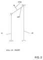
- FIG. 2is a diagram illustrating a DWS heading calculation.
- FIG. 3is a block diagram illustrating known initial wheel radius learning with a long term, low-weighted correction factor.
- FIG. 4is a block diagram illustrating initial wheel radius learning with a long term, low weighted correction factor as adjusted by a short term, high weighted correction factor.
- the navigation system 110has a navigation application 210 accepting inputs from a vehicle positioning application 240 .
- the vehicle positioning application 240uses the outputs of sensors 125 .
- the sensors 125include a GPS receiver 272 , speed pulse sensors 276 , a differential wheel speed sensor 277 and a forward/reverse sensor 278 .
- the vehicle positioning application 240may use the outputs of additional sensors 279 .
- the outputs of the sensors 125may be affected by many variable factors, such as the ambient temperature, the age of the sensor, and the stability of the power supply as well as other factors that are difficult or impossible to control. Accordingly, the vehicle positioning application 240 generally treats sensor measurements as approximations to be weighted according to confidence factors.
- the GPS (Global Positioning System) receiver 272 on board the vehicle 111uses signals from a constellation of a plurality of satellites to compute the position of the GPS receiver 272 relative to the earth.
- the GPS satellitestransmit signals on different frequencies which are received by the GPS receiver 272 .
- the position calculated by the GPS receiver 272is an estimate of the true position on the earth. The calculated position may be in error or inaccurate due to such factors as multipath interference, atmospheric distortion, and so on.
- GPSis used as one sensor to calculate absolute wheel radii, distance, and heading as known by various techniques in the art.
- Each speed pulse sensor 276is a type of sensor used to indicate the distance traveled by the vehicle 111 .
- the speed pulse sensor 276outputs a number of speed pulses per wheel rotation, using a sensor responsive to wheel rotation, such as for example, a permanent magnet Hall effect sensor, Wiegand effect sensor, an optical sensor, or other type of sensor, located at the wheel rim.
- the number of pulses reported by this sensoris proportional to the distance traveled by the vehicle 111 . This value can be used to compute the speed of the vehicle 111 according to distance traveled in a given time, as known in the art. However, as noted, correction factors may need to be applied.
- heading changesare measured, or calculated, by the DWS sensor 277 .
- the DWS sensor 277takes wheel speed sensor reports from a paired left wheel and right wheel, e.g. the front wheels or the back wheels, and uses the paired wheel speed sensor reports to calculate the change in heading of the vehicle.
- a paired left wheel and right wheele.g. the front wheels or the back wheels
- the use of an accurate, non-lossy, DWS sensormay be important for utilization of the navigation system when the vehicle is traveling at low speeds, e.g., under 25 mph.
- each wheel of a left and right opposing pair of wheelshas traveled a different distance, and this distance can be used to determine a change of heading value using the following formula:
- ⁇ Hdg( dL ⁇ dR )/ dWT (1)
- dLis distance traveled as input from, or reported by, the left wheel sensor
- dRis distance traveled as input from, or reported, by the right wheel sensor
- dWTis the distance between the left wheel and the right wheel, sometimes called
- Dynamic factorsinclude high-speed driving and lateral acceleration, such as through an on-ramp to a highway, with the forces involved decreasing the radius of the outside tire and increasing the radius of the inside tire.
- the vehicle wheel radiusmay change statically due to adding or removing weight from the vehicle, inflation or deflation of the tires, etc., thereby causing non-uniform changes in the wheel radius.
- Use of the DWS heading by the vehicle positioning application 240would desirably account for both static and dynamic changes of wheel radii.
- One present embodimentincludes techniques to correct the effects of wheel radius changes on the differential wheel speed (DWS) heading change determination of a vehicle positioning application for an in-vehicle navigation system.
- the wheel radius determinationcan be important in determining the DWS heading change with sufficient accuracy.
- the modeling of the effects imparted to the DWS heading determination by changing wheel radiican also be important when using a vehicle positioning application so that the DWS heading can be realistically weighted as a factor in correcting, or determining the confidence of, the vehicle position determination when compared to all sensor system calculations of the vehicle positioning application.
- the effects of lateral acceleration on the vehicle wheel radiimay cause up to approximately a 30% heading error for a vehicle traveling through an on or off ramp maneuver.
- the lateral acceleration involvedcauses a force on the outside tire causing the outer wheel's radius to compress.
- the forcecauses the inner wheel's radius to increase.
- alatis an estimated lateral acceleration value
- Distis the distance traveled at the lateral acceleration as taken from the wheel speed sensors.
- Kcaris a vehicle dependent constant.
- the estimated lateral acceleration value, alatcan be determined by multiplying the estimated yaw rate by the vehicle speed.
- DWS datacan be used to estimate the yaw rate, or heading change, by using the formula dl ⁇ dr/dWT.
- Vehicle speedcan be estimated using the wheel speed sensor data.
- the Kcar factorcan be dependent on the individual vehicle characteristics including center of gravity of the vehicle, stiffness of tires, overall weight of the vehicle, and suspension characteristics. For each turn, the Kcar factor can be learned according to the below formula.
- a turn detection algorithmdescribed in the above referenced U.S. Pat. No. 6,317,683, can be used to trigger a relearning or recalculation of the Kcar factor each time the vehicle goes through a detected turn.
- the referenced turn detection algorithmoperates by detecting changes of DWS heading over a preselected number of degrees and comparing a presumed turn to data acquired from the GPS data stream. If the GPS heading is not available at the beginning or end of the turn, or is not deemed reliable due to inappropriate conditions, such as in the instance where the vehicle is not traveling at a sufficient speed to trust the GPS, e.g., greater than 25 mph, or the GPS heading value does not match the detected turn, then turn detection is not used, resulting in no Kcar update value.
- DWS headingi.e., change in DWS heading equals DWS heading value minus a correction factor of car characteristics times lateral acceleration factors.
- the updated Kcar factorcan be calculated (for each detected turn) according to the following formula:
- Equation 2
- Kcarchange((( dL ⁇ dR )/ dWT ⁇ Kcar (old)* abs ( Dist*alat )) ⁇ Hdg )/SUM( alat*Dist ) (5)
- Kcarupdated (which becomes Kcarold of formula 1)Kcarold (known) ⁇ Kcarchange (calculated) (6)
- abs(Dist*alat)is the absolute value of distance through the turn times alat
- SUM(alat*Dist)is the piecewise summation of the absolute (lateral acceleration*Distance) computations (e.g., done at 1/second) during the turn;
- ⁇ Hdgis the change of heading value from ⁇ HdgGPS value used by the vehicle positioning application from beginning to end of turn due to the high confidence value placed on GPS values under appropriate conditions;
- ⁇ HdgDWSis the change of heading value to the heading change calculated using DWS sensors.
- dL ⁇ dRcan be derived from reported values
- dWTis a known value
- Kcar (old)is a known, i.e., previously learned value
- alatcan be an estimated value derived from the vehicle speed and heading sensors
- Distcan be a measured value from the vehicle sensors. Due to some inexact value estimates taken from raw sensor data in the learning of the Kcar factor, the Kcar factor retains some potential error in the heading change. This error can be further modeled to add further compensation for this error. Error modeling can be accomplished in the vehicle positioning application using a percentage of the magnitude of the lateral acceleration (alat)*distance (Dist) to determine the error in the computed heading change.
- adding and removing weight from the vehicle or tire inflation/deflationmay cause non-uniform changes in the wheel radius. For example, if the left wheel is inflated by 3 psi, the wheel radius may change by about 0.1%. For a vehicle with a wheel track of 1.5 meters, a bias of 4 degrees may be introduced for every 100 meters traveled. It would be preferable to reduce this amount.
- a short term learning algorithmis implemented to help more quickly learn non-uniform radius changes. This short-term algorithm has the advantage of eliminating, or reducing, the error bias when adding weight to a vehicle or when inflating tires.
- FIG. 3a block diagram of the initial wheel radius learning is shown.
- Inputs from the left and right speed pulse sensors (the components of the DWS sensor) SPL, SPR, and position information from the GPS sensorare entered to a data sample radius calculation operation 305 .
- a known wheel radius learning calculation operation 310only weighs each new sample of the GPS wheel radius calculation by ⁇ fraction (1/500) ⁇ . Noting that GPS position acquisition time may be on the order of thirty seconds to three minutes, this has the effect of taking a relatively long time to learn inter-wheel radius changes.
- a short-term learning mechanismis introduced.
- an exemplary embodimentrecognizes that it can be useful to correct for wheel radii changes in the short term by figuring the differential of the paired-wheel radii according to the DWS sensors, as at DWS radii calculation operation 315 , rather than relying on the absolute values of each wheel radius calculated using GPS speed calculations as at 305 .
- the differential radii calculation operation 315can be performed to obtain values which are operably accurate and obtained from a data stream sampled more quickly than the GPS.
- the inter-wheel radiimay be sampled at once per second, yielding far greater sampling rates and new values rLnew, rRnew to update the long term, low weighted calculation operation 310 thus obtaining operable radii values within about one minute.
- the short term differential radius learning taken from the DWS sensorsis more likely to be uninterrupted and reliably reported without dependence on receiving the GPS signal.
- the short term algorithm correctiontakes advantage of the knowledge that the major error source in the radii learning is biased by the GPS errors. However, both the left and right wheel radii learning are biased substantially equally by these errors. Therefore the differential value between the left wheel and the right wheel remains substantially valid.
- the inter-wheel radii differential correctioncan be continuously performed. A weighting to reduce the difference between the newly calculated, or reported, wheel differential and the previous wheel differential can then be performed. To avoid situations where the inter-wheel radius differential is incorrectly reported, the short-term learning is not overly aggressive in its correction of the previous value. Further, the short term learning may include outlier detection and filtering of each radius sampling, according to known techniques, to ensure that the newly learned wheel radii differential is accurate. The newly calculated wheel radii differential is only calculated from selected series of samples if the variances of the samples are low and no outliers are detected.
- the inter-wheel radius differentialwill be changed by half wherein each wheel radius value is adjusted by one quarter of the apparent error.
- the short-term learningcan help the navigation system learn the inter-wheel radius differential much faster than absolute radii calculations utilizing GPS, thereby reducing the heading errors and enabling the DWS heading calculations to be implemented in a workable navigation system.
- the values given in the examples hereinare, of course, dependent upon the overall weighting which the differential radii calculation may be given to maintain an acceptable level of accuracy or confidence in the radii value.
- the inter-wheel radius differential valueequals the left wheel radius minus the right wheel radius.
- An updated, or new, inter-wheel radius differential value, drnewis calculated according to:
- the averagecan be based on a given number (e.g., 5-10) of samples.
- the drnew valuewill only be used if the variance of the samples is low and no outliers are detected, thereby indicating that the drnew value is valid. Then,if
- a vehicle positionmay determined relative to data in a geographic database.
- the vehiclemay be a pneumatically tired car, truck, bus, tricycle, or any other kind of vehicle with varying radii left/right opposing wheels that can travel along roads.
- an embodiment of the DWS heading change determinations for a vehicle positioning programcan be used in a navigation system that is similar to the system described in U.S. Pat. No. 6,317,683.
- the DWS heading change determination programming disclosed in the present specificationis not limited to use only in a system like the one described in U.S. Pat. No. 6,317,683.
Landscapes
- Engineering & Computer Science (AREA)
- Radar, Positioning & Navigation (AREA)
- Remote Sensing (AREA)
- Automation & Control Theory (AREA)
- Physics & Mathematics (AREA)
- General Physics & Mathematics (AREA)
- Navigation (AREA)
- Control Of Driving Devices And Active Controlling Of Vehicle (AREA)
Abstract
Description
Claims (15)
Priority Applications (1)
| Application Number | Priority Date | Filing Date | Title |
|---|---|---|---|
| US10/055,497US6631321B1 (en) | 2001-10-29 | 2001-10-29 | Vehicle heading change determination using compensated differential wheel speed |
Applications Claiming Priority (1)
| Application Number | Priority Date | Filing Date | Title |
|---|---|---|---|
| US10/055,497US6631321B1 (en) | 2001-10-29 | 2001-10-29 | Vehicle heading change determination using compensated differential wheel speed |
Publications (1)
| Publication Number | Publication Date |
|---|---|
| US6631321B1true US6631321B1 (en) | 2003-10-07 |
Family
ID=28673424
Family Applications (1)
| Application Number | Title | Priority Date | Filing Date |
|---|---|---|---|
| US10/055,497Expired - LifetimeUS6631321B1 (en) | 2001-10-29 | 2001-10-29 | Vehicle heading change determination using compensated differential wheel speed |
Country Status (1)
| Country | Link |
|---|---|
| US (1) | US6631321B1 (en) |
Cited By (17)
| Publication number | Priority date | Publication date | Assignee | Title |
|---|---|---|---|---|
| US20100241355A1 (en)* | 2007-05-14 | 2010-09-23 | Thinkware Systems Corporation | Method for correcting map matching and navigation system implementing the method |
| US20120022780A1 (en)* | 2010-07-22 | 2012-01-26 | Qualcomm Incorporated | Apparatus and methods for calibrating dynamic parameters of a vehicle navigation system |
| US20130268172A1 (en)* | 2012-04-04 | 2013-10-10 | Vishram Vinayak Nandedkar | Method and system for identifying an erroneous speed of a vehicle |
| US8696010B2 (en) | 2010-12-15 | 2014-04-15 | Symbotic, LLC | Suspension system for autonomous transports |
| US8965619B2 (en) | 2010-12-15 | 2015-02-24 | Symbotic, LLC | Bot having high speed stability |
| US9187244B2 (en) | 2010-12-15 | 2015-11-17 | Symbotic, LLC | BOT payload alignment and sensing |
| US9321591B2 (en) | 2009-04-10 | 2016-04-26 | Symbotic, LLC | Autonomous transports for storage and retrieval systems |
| US9499338B2 (en) | 2010-12-15 | 2016-11-22 | Symbotic, LLC | Automated bot transfer arm drive system |
| US9561905B2 (en) | 2010-12-15 | 2017-02-07 | Symbotic, LLC | Autonomous transport vehicle |
| US9771217B2 (en) | 2009-04-10 | 2017-09-26 | Symbotic, LLC | Control system for storage and retrieval systems |
| US10024977B1 (en) | 2015-02-18 | 2018-07-17 | Ag Leader Technology, Inc. | Low speed heading measurement |
| US10225683B1 (en)* | 2010-08-02 | 2019-03-05 | Intellectual Ventures Fund 79 Llc | Systems, methods, and mediums for receiving reminders and/or identifying available goods and/or services |
| CN110274589A (en)* | 2018-03-15 | 2019-09-24 | 高德信息技术有限公司 | A kind of localization method and device |
| US10697795B2 (en)* | 2018-02-12 | 2020-06-30 | Bell Textron Inc. | Automatic heading correction for directional gyroscopes |
| US10894663B2 (en) | 2013-09-13 | 2021-01-19 | Symbotic Llc | Automated storage and retrieval system |
| US11078017B2 (en) | 2010-12-15 | 2021-08-03 | Symbotic Llc | Automated bot with transfer arm |
| CN114254268A (en)* | 2022-02-28 | 2022-03-29 | 南开大学 | Automatic following algorithm and system |
Citations (29)
| Publication number | Priority date | Publication date | Assignee | Title |
|---|---|---|---|---|
| US4796191A (en) | 1984-06-07 | 1989-01-03 | Etak, Inc. | Vehicle navigational system and method |
| US4807127A (en) | 1986-12-10 | 1989-02-21 | Sumitomo Electric Industries, Ltd. | Vehicle location detecting system |
| US4814989A (en) | 1985-05-30 | 1989-03-21 | Robert Bosch Gmbh | Navigation method for vehicles |
| US4964052A (en) | 1987-10-30 | 1990-10-16 | Nec Home Electronics Ltd. | Navigation device for use in a vehicle |
| US4999783A (en) | 1987-05-11 | 1991-03-12 | Sumitomo Electric Industries, Ltd. | Location detecting method |
| US5058023A (en) | 1990-07-30 | 1991-10-15 | Motorola, Inc. | Vehicle position determining apparatus |
| US5119301A (en) | 1989-04-17 | 1992-06-02 | Sumitomo Electric Industries, Ltd. | Vehicle location detecting system |
| US5155688A (en) | 1989-10-24 | 1992-10-13 | Mitsubishi Denki Kabushiki Kaisha | Vehicle navigation system |
| US5311173A (en) | 1988-09-16 | 1994-05-10 | Hitachi, Ltd. | Navigation system and method using map data |
| US5311195A (en) | 1991-08-30 | 1994-05-10 | Etak, Inc. | Combined relative and absolute positioning method and apparatus |
| US5334986A (en) | 1992-04-09 | 1994-08-02 | U.S. Philips Corporation | Device for determining the position of a vehicle |
| US5359529A (en) | 1992-05-15 | 1994-10-25 | Zexel Corporation | Route guidance on/off-route state filter |
| US5374933A (en) | 1993-01-05 | 1994-12-20 | Zexel Corporation | Position correction method for vehicle navigation system |
| US5422815A (en) | 1992-12-14 | 1995-06-06 | Pioneer Electronic Corporation | Navigation apparatus and navigation method |
| US5422639A (en) | 1992-09-16 | 1995-06-06 | Xanavi Informatics Corporation | Navigation equipment which determines current position dependent on difference between calculated value of self-contained navigation and measured value of radio navigation |
| US5428545A (en) | 1993-01-11 | 1995-06-27 | Mitsubishi Denki Kabushiki Kaisha | Vehicle guiding system responsive to estimated congestion |
| US5483456A (en) | 1992-11-04 | 1996-01-09 | Pioneer Electronic Corporation | Navigation system and a method of calculating GPS measuring deviation |
| US5493294A (en) | 1992-04-15 | 1996-02-20 | Sumitomo Electric Industries, Ltd. | Apparatus for detecting the position of a vehicle |
| US5523765A (en) | 1993-06-10 | 1996-06-04 | Alpine Electronics, Inc. | Method and apparatus for detecting vehicle location for a vehicle navigation system |
| US5552990A (en) | 1991-05-21 | 1996-09-03 | Matsushita Electric Industrial Co., Ltd. | Vehicle position detecting apparatus which comensates for errors in road map data matching operation |
| US5852791A (en) | 1995-12-28 | 1998-12-22 | Alpine Electronics | Vehicle navigation with vehicle position correction feature |
| US5912635A (en) | 1995-09-14 | 1999-06-15 | Visteon Technologies, Inc. | Method and apparatus for calibration of a distance sensor in a vehicle navigation system |
| US5995897A (en)* | 1996-05-01 | 1999-11-30 | Nisshinbo Industries Inc. | Vehicle control method using short-term and long-term correction coefficients to determine turn status |
| US6041280A (en) | 1996-03-15 | 2000-03-21 | Sirf Technology, Inc. | GPS car navigation system |
| WO2000050917A1 (en) | 1999-02-22 | 2000-08-31 | Magellan Dis Inc. | Vehicle navigation system with correction for selective availability |
| US6167347A (en) | 1998-11-04 | 2000-12-26 | Lin; Ching-Fang | Vehicle positioning method and system thereof |
| US6192312B1 (en) | 1999-03-25 | 2001-02-20 | Navigation Technologies Corp. | Position determining program and method |
| US6230100B1 (en)* | 1997-01-31 | 2001-05-08 | Motorola, Inc. | Method and apparatus for differential scale factor calibration in differential odometry systems integrated with GPS |
| US6360165B1 (en) | 1999-10-21 | 2002-03-19 | Visteon Technologies, Llc | Method and apparatus for improving dead reckoning distance calculation in vehicle navigation system |
- 2001
- 2001-10-29USUS10/055,497patent/US6631321B1/ennot_activeExpired - Lifetime
Patent Citations (30)
| Publication number | Priority date | Publication date | Assignee | Title |
|---|---|---|---|---|
| US4796191A (en) | 1984-06-07 | 1989-01-03 | Etak, Inc. | Vehicle navigational system and method |
| US4814989A (en) | 1985-05-30 | 1989-03-21 | Robert Bosch Gmbh | Navigation method for vehicles |
| US4807127A (en) | 1986-12-10 | 1989-02-21 | Sumitomo Electric Industries, Ltd. | Vehicle location detecting system |
| US4999783A (en) | 1987-05-11 | 1991-03-12 | Sumitomo Electric Industries, Ltd. | Location detecting method |
| US4964052A (en) | 1987-10-30 | 1990-10-16 | Nec Home Electronics Ltd. | Navigation device for use in a vehicle |
| US5311173A (en) | 1988-09-16 | 1994-05-10 | Hitachi, Ltd. | Navigation system and method using map data |
| US5119301A (en) | 1989-04-17 | 1992-06-02 | Sumitomo Electric Industries, Ltd. | Vehicle location detecting system |
| US5155688A (en) | 1989-10-24 | 1992-10-13 | Mitsubishi Denki Kabushiki Kaisha | Vehicle navigation system |
| US5058023A (en) | 1990-07-30 | 1991-10-15 | Motorola, Inc. | Vehicle position determining apparatus |
| US5552990A (en) | 1991-05-21 | 1996-09-03 | Matsushita Electric Industrial Co., Ltd. | Vehicle position detecting apparatus which comensates for errors in road map data matching operation |
| US5311195A (en) | 1991-08-30 | 1994-05-10 | Etak, Inc. | Combined relative and absolute positioning method and apparatus |
| US5334986A (en) | 1992-04-09 | 1994-08-02 | U.S. Philips Corporation | Device for determining the position of a vehicle |
| US5493294A (en) | 1992-04-15 | 1996-02-20 | Sumitomo Electric Industries, Ltd. | Apparatus for detecting the position of a vehicle |
| US5359529A (en) | 1992-05-15 | 1994-10-25 | Zexel Corporation | Route guidance on/off-route state filter |
| US5508931A (en) | 1992-05-15 | 1996-04-16 | Zexel Corporation | Route guidance on/off-route state filter |
| US5422639A (en) | 1992-09-16 | 1995-06-06 | Xanavi Informatics Corporation | Navigation equipment which determines current position dependent on difference between calculated value of self-contained navigation and measured value of radio navigation |
| US5483456A (en) | 1992-11-04 | 1996-01-09 | Pioneer Electronic Corporation | Navigation system and a method of calculating GPS measuring deviation |
| US5422815A (en) | 1992-12-14 | 1995-06-06 | Pioneer Electronic Corporation | Navigation apparatus and navigation method |
| US5374933A (en) | 1993-01-05 | 1994-12-20 | Zexel Corporation | Position correction method for vehicle navigation system |
| US5428545A (en) | 1993-01-11 | 1995-06-27 | Mitsubishi Denki Kabushiki Kaisha | Vehicle guiding system responsive to estimated congestion |
| US5523765A (en) | 1993-06-10 | 1996-06-04 | Alpine Electronics, Inc. | Method and apparatus for detecting vehicle location for a vehicle navigation system |
| US5912635A (en) | 1995-09-14 | 1999-06-15 | Visteon Technologies, Inc. | Method and apparatus for calibration of a distance sensor in a vehicle navigation system |
| US5852791A (en) | 1995-12-28 | 1998-12-22 | Alpine Electronics | Vehicle navigation with vehicle position correction feature |
| US6041280A (en) | 1996-03-15 | 2000-03-21 | Sirf Technology, Inc. | GPS car navigation system |
| US5995897A (en)* | 1996-05-01 | 1999-11-30 | Nisshinbo Industries Inc. | Vehicle control method using short-term and long-term correction coefficients to determine turn status |
| US6230100B1 (en)* | 1997-01-31 | 2001-05-08 | Motorola, Inc. | Method and apparatus for differential scale factor calibration in differential odometry systems integrated with GPS |
| US6167347A (en) | 1998-11-04 | 2000-12-26 | Lin; Ching-Fang | Vehicle positioning method and system thereof |
| WO2000050917A1 (en) | 1999-02-22 | 2000-08-31 | Magellan Dis Inc. | Vehicle navigation system with correction for selective availability |
| US6192312B1 (en) | 1999-03-25 | 2001-02-20 | Navigation Technologies Corp. | Position determining program and method |
| US6360165B1 (en) | 1999-10-21 | 2002-03-19 | Visteon Technologies, Llc | Method and apparatus for improving dead reckoning distance calculation in vehicle navigation system |
Cited By (49)
| Publication number | Priority date | Publication date | Assignee | Title |
|---|---|---|---|---|
| US8321128B2 (en)* | 2007-05-14 | 2012-11-27 | Thinkware Systems Corporation | Method for correcting map matching and navigation system implementing the method |
| US20100241355A1 (en)* | 2007-05-14 | 2010-09-23 | Thinkware Systems Corporation | Method for correcting map matching and navigation system implementing the method |
| US10759600B2 (en) | 2009-04-10 | 2020-09-01 | Symbotic Llc | Autonomous transports for storage and retrieval systems |
| US9771217B2 (en) | 2009-04-10 | 2017-09-26 | Symbotic, LLC | Control system for storage and retrieval systems |
| US10207870B2 (en) | 2009-04-10 | 2019-02-19 | Symbotic, LLC | Autonomous transports for storage and retrieval systems |
| US10239691B2 (en) | 2009-04-10 | 2019-03-26 | Symbotic, LLC | Storage and retrieval system |
| US12358723B2 (en) | 2009-04-10 | 2025-07-15 | Symbotic Llc | Storage and retrieval system |
| US9321591B2 (en) | 2009-04-10 | 2016-04-26 | Symbotic, LLC | Autonomous transports for storage and retrieval systems |
| US11939158B2 (en) | 2009-04-10 | 2024-03-26 | Symbotic Llc | Storage and retrieval system |
| US11858740B2 (en) | 2009-04-10 | 2024-01-02 | Symbotic Llc | Storage and retrieval system |
| US11661279B2 (en) | 2009-04-10 | 2023-05-30 | Symbotic Llc | Autonomous transports for storage and retrieval systems |
| US11254501B2 (en) | 2009-04-10 | 2022-02-22 | Symbotic Llc | Storage and retrieval system |
| US11124361B2 (en) | 2009-04-10 | 2021-09-21 | Symbotic Llc | Storage and retrieval system |
| CN103026176B (en)* | 2010-07-22 | 2016-03-09 | 高通股份有限公司 | For calibrating the device and method of the dynamic parameter of Vehicular navigation system |
| US8843290B2 (en)* | 2010-07-22 | 2014-09-23 | Qualcomm Incorporated | Apparatus and methods for calibrating dynamic parameters of a vehicle navigation system |
| WO2012012775A1 (en)* | 2010-07-22 | 2012-01-26 | Qualcomm Incorporated | Apparatus and methods for calibrating dynamic parameters of a vehicle navigation system |
| CN103026176A (en)* | 2010-07-22 | 2013-04-03 | 高通股份有限公司 | Apparatus and methods for calibrating dynamic parameters of a vehicle navigation system |
| US20120022780A1 (en)* | 2010-07-22 | 2012-01-26 | Qualcomm Incorporated | Apparatus and methods for calibrating dynamic parameters of a vehicle navigation system |
| US12418769B2 (en) | 2010-08-02 | 2025-09-16 | Intellectual Ventures Fund 79 Llc | Systems, methods, and mediums for receiving reminders and/or identifying available goods and/or services |
| US10225683B1 (en)* | 2010-08-02 | 2019-03-05 | Intellectual Ventures Fund 79 Llc | Systems, methods, and mediums for receiving reminders and/or identifying available goods and/or services |
| US9946265B2 (en) | 2010-12-15 | 2018-04-17 | Symbotic, LLC | Bot having high speed stability |
| US8696010B2 (en) | 2010-12-15 | 2014-04-15 | Symbotic, LLC | Suspension system for autonomous transports |
| US9862543B2 (en) | 2010-12-15 | 2018-01-09 | Symbiotic, LLC | Bot payload alignment and sensing |
| US9908698B2 (en) | 2010-12-15 | 2018-03-06 | Symbotic, LLC | Automated bot transfer arm drive system |
| US9561905B2 (en) | 2010-12-15 | 2017-02-07 | Symbotic, LLC | Autonomous transport vehicle |
| US8965619B2 (en) | 2010-12-15 | 2015-02-24 | Symbotic, LLC | Bot having high speed stability |
| US9550225B2 (en) | 2010-12-15 | 2017-01-24 | Symbotic Llc | Bot having high speed stability |
| US9499338B2 (en) | 2010-12-15 | 2016-11-22 | Symbotic, LLC | Automated bot transfer arm drive system |
| US9423796B2 (en) | 2010-12-15 | 2016-08-23 | Symbotic Llc | Bot having high speed stability |
| US10280000B2 (en) | 2010-12-15 | 2019-05-07 | Symbotic, LLC | Suspension system for autonomous transports |
| US10414586B2 (en) | 2010-12-15 | 2019-09-17 | Symbotic, LLC | Autonomous transport vehicle |
| US8919801B2 (en) | 2010-12-15 | 2014-12-30 | Symbotic, LLC | Suspension system for autonomous transports |
| US10683169B2 (en) | 2010-12-15 | 2020-06-16 | Symbotic, LLC | Automated bot transfer arm drive system |
| US12214959B2 (en) | 2010-12-15 | 2025-02-04 | Symbotic Llc | Automated bot with transfer arm |
| US9327903B2 (en) | 2010-12-15 | 2016-05-03 | Symbotic, LLC | Suspension system for autonomous transports |
| US9676551B2 (en) | 2010-12-15 | 2017-06-13 | Symbotic, LLC | Bot payload alignment and sensing |
| US11078017B2 (en) | 2010-12-15 | 2021-08-03 | Symbotic Llc | Automated bot with transfer arm |
| US9187244B2 (en) | 2010-12-15 | 2015-11-17 | Symbotic, LLC | BOT payload alignment and sensing |
| US9156394B2 (en) | 2010-12-15 | 2015-10-13 | Symbotic, LLC | Suspension system for autonomous transports |
| US11273981B2 (en) | 2010-12-15 | 2022-03-15 | Symbolic Llc | Automated bot transfer arm drive system |
| US11952214B2 (en) | 2010-12-15 | 2024-04-09 | Symbotic Llc | Automated bot transfer arm drive system |
| US20130268172A1 (en)* | 2012-04-04 | 2013-10-10 | Vishram Vinayak Nandedkar | Method and system for identifying an erroneous speed of a vehicle |
| US8874345B2 (en)* | 2012-04-04 | 2014-10-28 | General Electric Company | Method and system for identifying an erroneous speed of a vehicle |
| US10894663B2 (en) | 2013-09-13 | 2021-01-19 | Symbotic Llc | Automated storage and retrieval system |
| US11708218B2 (en) | 2013-09-13 | 2023-07-25 | Symbolic Llc | Automated storage and retrieval system |
| US10024977B1 (en) | 2015-02-18 | 2018-07-17 | Ag Leader Technology, Inc. | Low speed heading measurement |
| US10697795B2 (en)* | 2018-02-12 | 2020-06-30 | Bell Textron Inc. | Automatic heading correction for directional gyroscopes |
| CN110274589A (en)* | 2018-03-15 | 2019-09-24 | 高德信息技术有限公司 | A kind of localization method and device |
| CN114254268A (en)* | 2022-02-28 | 2022-03-29 | 南开大学 | Automatic following algorithm and system |
Similar Documents
| Publication | Publication Date | Title |
|---|---|---|
| US6631321B1 (en) | Vehicle heading change determination using compensated differential wheel speed | |
| JP4550255B2 (en) | Method and apparatus for improving dead reckoning distance calculations for vehicle navigation systems | |
| US4788645A (en) | Method and apparatus for measuring relative heading changes in a vehicular onboard navigation system | |
| EP1439371B1 (en) | Road shape data preparation method | |
| KR100272901B1 (en) | Apparatus and method for calibrating the distance detector of a vehicle navigation system | |
| CN102007417B (en) | Calibration algorithm for yaw rate sensor calibration based on vehicle sensor | |
| US6597987B1 (en) | Method for improving vehicle positioning in a navigation system | |
| US5784029A (en) | Recognition of and method and apparatus for GPS antenna lever arm compensation in integrated GPS/dead reckoning navigation systems | |
| US20020022924A1 (en) | Propagation of position with multiaxis accelerometer | |
| JP3112405B2 (en) | Vehicle position detection device | |
| CN111902693B (en) | Method for calibrating a gyroscope equipped in a vehicle | |
| JPH07301541A (en) | Navigation device | |
| JP3451636B2 (en) | Speed sensor coefficient calculation device | |
| JP3440180B2 (en) | Navigation device | |
| EP0944812B1 (en) | Method and apparatus for calibration of the wheel track | |
| US5752220A (en) | Method for heading error suppression in dead reckoning systems | |
| JP3581392B2 (en) | Integral sensing device | |
| KR101676145B1 (en) | Curvature calculation device and curvature correction method | |
| JPH0634379A (en) | Navigation device | |
| JP2668249B2 (en) | Method and device for measuring relative direction changes in an in-vehicle navigation system | |
| JP2590608B2 (en) | Vehicle running direction calculation device | |
| JPH0335115A (en) | Navigation device and bearing indicator for moving body | |
| JPH11271050A (en) | Body slip angle measuring device | |
| HK1003232B (en) | Method and apparatus for measuring relative heading changes in a vehicular onboard navigation system | |
| JP2003094921A (en) | Tire initial error correction coefficient calculation method and apparatus, tire air pressure drop detecting apparatus using the same, and tire initial error correction coefficient calculation program |
Legal Events
| Date | Code | Title | Description |
|---|---|---|---|
| AS | Assignment | Owner name:NAVIGATION TECHNOLOGIES CORPORATION, ILLINOIS Free format text:ASSIGNMENT OF ASSIGNORS INTEREST;ASSIGNOR:CIPRIAN, JOSEPH;REEL/FRAME:012560/0134 Effective date:20011029 | |
| STCF | Information on status: patent grant | Free format text:PATENTED CASE | |
| AS | Assignment | Owner name:NAVTEQ CORPORATION, ILLINOIS Free format text:ASSIGNMENT OF ASSIGNORS INTEREST;ASSIGNOR:NAVIGATION TECHNOLOGIES CORPORATION;REEL/FRAME:015293/0400 Effective date:20040203 Owner name:NAVTEQ NORTH AMERICA LLC, ILLINOIS Free format text:ASSIGNMENT OF ASSIGNORS INTEREST;ASSIGNOR:NAVTEQ CORPORATION;REEL/FRAME:015286/0504 Effective date:20040510 Owner name:NAVTEQ NORTH AMERICA LLC,ILLINOIS Free format text:ASSIGNMENT OF ASSIGNORS INTEREST;ASSIGNOR:NAVTEQ CORPORATION;REEL/FRAME:015286/0504 Effective date:20040510 Owner name:NAVTEQ CORPORATION,ILLINOIS Free format text:ASSIGNMENT OF ASSIGNORS INTEREST;ASSIGNOR:NAVIGATION TECHNOLOGIES CORPORATION;REEL/FRAME:015293/0400 Effective date:20040203 | |
| FPAY | Fee payment | Year of fee payment:4 | |
| FPAY | Fee payment | Year of fee payment:8 | |
| AS | Assignment | Owner name:NAVTEQ B.V., NETHERLANDS Free format text:ASSIGNMENT OF ASSIGNORS INTEREST;ASSIGNOR:NAVTEQ NORTH AMERICA, LLC;REEL/FRAME:027588/0051 Effective date:20111229 | |
| AS | Assignment | Owner name:HERE GLOBAL B.V., NETHERLANDS Free format text:CHANGE OF NAME;ASSIGNOR:NAVTEQ B.V.;REEL/FRAME:033830/0681 Effective date:20130423 | |
| FPAY | Fee payment | Year of fee payment:12 |