US6631287B2 - Infrared thermometer - Google Patents
Infrared thermometerDownload PDFInfo
- Publication number
- US6631287B2 US6631287B2US09/825,478US82547801AUS6631287B2US 6631287 B2US6631287 B2US 6631287B2US 82547801 AUS82547801 AUS 82547801AUS 6631287 B2US6631287 B2US 6631287B2
- Authority
- US
- United States
- Prior art keywords
- sensor array
- temperature
- recited
- medical target
- target area
- Prior art date
- Legal status (The legal status is an assumption and is not a legal conclusion. Google has not performed a legal analysis and makes no representation as to the accuracy of the status listed.)
- Expired - Lifetime, expires
Links
Images


Classifications
- G—PHYSICS
- G01—MEASURING; TESTING
- G01J—MEASUREMENT OF INTENSITY, VELOCITY, SPECTRAL CONTENT, POLARISATION, PHASE OR PULSE CHARACTERISTICS OF INFRARED, VISIBLE OR ULTRAVIOLET LIGHT; COLORIMETRY; RADIATION PYROMETRY
- G01J5/00—Radiation pyrometry, e.g. infrared or optical thermometry
- G01J5/02—Constructional details
- G01J5/04—Casings
- G—PHYSICS
- G01—MEASURING; TESTING
- G01J—MEASUREMENT OF INTENSITY, VELOCITY, SPECTRAL CONTENT, POLARISATION, PHASE OR PULSE CHARACTERISTICS OF INFRARED, VISIBLE OR ULTRAVIOLET LIGHT; COLORIMETRY; RADIATION PYROMETRY
- G01J5/00—Radiation pyrometry, e.g. infrared or optical thermometry
- G01J5/02—Constructional details
- G01J5/0205—Mechanical elements; Supports for optical elements
- G—PHYSICS
- G01—MEASURING; TESTING
- G01J—MEASUREMENT OF INTENSITY, VELOCITY, SPECTRAL CONTENT, POLARISATION, PHASE OR PULSE CHARACTERISTICS OF INFRARED, VISIBLE OR ULTRAVIOLET LIGHT; COLORIMETRY; RADIATION PYROMETRY
- G01J5/00—Radiation pyrometry, e.g. infrared or optical thermometry
- G01J5/02—Constructional details
- G01J5/025—Interfacing a pyrometer to an external device or network; User interface
- G—PHYSICS
- G01—MEASURING; TESTING
- G01J—MEASUREMENT OF INTENSITY, VELOCITY, SPECTRAL CONTENT, POLARISATION, PHASE OR PULSE CHARACTERISTICS OF INFRARED, VISIBLE OR ULTRAVIOLET LIGHT; COLORIMETRY; RADIATION PYROMETRY
- G01J5/00—Radiation pyrometry, e.g. infrared or optical thermometry
- G01J5/02—Constructional details
- G01J5/0265—Handheld, portable
- G—PHYSICS
- G01—MEASURING; TESTING
- G01J—MEASUREMENT OF INTENSITY, VELOCITY, SPECTRAL CONTENT, POLARISATION, PHASE OR PULSE CHARACTERISTICS OF INFRARED, VISIBLE OR ULTRAVIOLET LIGHT; COLORIMETRY; RADIATION PYROMETRY
- G01J5/00—Radiation pyrometry, e.g. infrared or optical thermometry
- G01J5/02—Constructional details
- G01J5/04—Casings
- G01J5/049—Casings for tympanic thermometers
- G—PHYSICS
- G01—MEASURING; TESTING
- G01J—MEASUREMENT OF INTENSITY, VELOCITY, SPECTRAL CONTENT, POLARISATION, PHASE OR PULSE CHARACTERISTICS OF INFRARED, VISIBLE OR ULTRAVIOLET LIGHT; COLORIMETRY; RADIATION PYROMETRY
- G01J5/00—Radiation pyrometry, e.g. infrared or optical thermometry
- G01J5/02—Constructional details
- G01J5/08—Optical arrangements
- G01J5/0806—Focusing or collimating elements, e.g. lenses or concave mirrors
- G—PHYSICS
- G01—MEASURING; TESTING
- G01J—MEASUREMENT OF INTENSITY, VELOCITY, SPECTRAL CONTENT, POLARISATION, PHASE OR PULSE CHARACTERISTICS OF INFRARED, VISIBLE OR ULTRAVIOLET LIGHT; COLORIMETRY; RADIATION PYROMETRY
- G01J5/00—Radiation pyrometry, e.g. infrared or optical thermometry
- G01J5/02—Constructional details
- G01J5/08—Optical arrangements
- G01J5/0813—Planar mirrors; Parallel phase plates
- G—PHYSICS
- G01—MEASURING; TESTING
- G01J—MEASUREMENT OF INTENSITY, VELOCITY, SPECTRAL CONTENT, POLARISATION, PHASE OR PULSE CHARACTERISTICS OF INFRARED, VISIBLE OR ULTRAVIOLET LIGHT; COLORIMETRY; RADIATION PYROMETRY
- G01J5/00—Radiation pyrometry, e.g. infrared or optical thermometry
- G01J5/02—Constructional details
- G01J5/08—Optical arrangements
- G01J5/0818—Waveguides
- G—PHYSICS
- G01—MEASURING; TESTING
- G01J—MEASUREMENT OF INTENSITY, VELOCITY, SPECTRAL CONTENT, POLARISATION, PHASE OR PULSE CHARACTERISTICS OF INFRARED, VISIBLE OR ULTRAVIOLET LIGHT; COLORIMETRY; RADIATION PYROMETRY
- G01J5/00—Radiation pyrometry, e.g. infrared or optical thermometry
- G01J5/02—Constructional details
- G01J5/08—Optical arrangements
- G01J5/0831—Masks; Aperture plates; Spatial light modulators
- G—PHYSICS
- G01—MEASURING; TESTING
- G01J—MEASUREMENT OF INTENSITY, VELOCITY, SPECTRAL CONTENT, POLARISATION, PHASE OR PULSE CHARACTERISTICS OF INFRARED, VISIBLE OR ULTRAVIOLET LIGHT; COLORIMETRY; RADIATION PYROMETRY
- G01J5/00—Radiation pyrometry, e.g. infrared or optical thermometry
- G01J5/02—Constructional details
- G01J5/08—Optical arrangements
- G01J5/084—Adjustable or slidable
- G—PHYSICS
- G01—MEASURING; TESTING
- G01J—MEASUREMENT OF INTENSITY, VELOCITY, SPECTRAL CONTENT, POLARISATION, PHASE OR PULSE CHARACTERISTICS OF INFRARED, VISIBLE OR ULTRAVIOLET LIGHT; COLORIMETRY; RADIATION PYROMETRY
- G01J5/00—Radiation pyrometry, e.g. infrared or optical thermometry
- G01J5/52—Radiation pyrometry, e.g. infrared or optical thermometry using comparison with reference sources, e.g. disappearing-filament pyrometer
- G01J5/53—Reference sources, e.g. standard lamps; Black bodies
- G—PHYSICS
- G01—MEASURING; TESTING
- G01J—MEASUREMENT OF INTENSITY, VELOCITY, SPECTRAL CONTENT, POLARISATION, PHASE OR PULSE CHARACTERISTICS OF INFRARED, VISIBLE OR ULTRAVIOLET LIGHT; COLORIMETRY; RADIATION PYROMETRY
- G01J5/00—Radiation pyrometry, e.g. infrared or optical thermometry
- G01J5/70—Passive compensation of pyrometer measurements, e.g. using ambient temperature sensing or sensing of temperature within housing
- G—PHYSICS
- G01—MEASURING; TESTING
- G01J—MEASUREMENT OF INTENSITY, VELOCITY, SPECTRAL CONTENT, POLARISATION, PHASE OR PULSE CHARACTERISTICS OF INFRARED, VISIBLE OR ULTRAVIOLET LIGHT; COLORIMETRY; RADIATION PYROMETRY
- G01J5/00—Radiation pyrometry, e.g. infrared or optical thermometry
- G01J2005/0077—Imaging
- G—PHYSICS
- G01—MEASURING; TESTING
- G01J—MEASUREMENT OF INTENSITY, VELOCITY, SPECTRAL CONTENT, POLARISATION, PHASE OR PULSE CHARACTERISTICS OF INFRARED, VISIBLE OR ULTRAVIOLET LIGHT; COLORIMETRY; RADIATION PYROMETRY
- G01J5/00—Radiation pyrometry, e.g. infrared or optical thermometry
- G01J5/48—Thermography; Techniques using wholly visual means
Definitions
- the inventionis directed to the field of diagnostic instruments and more particularly to a diagnostic instrument which is suitable for use with the ear or other medical/industrial target in order to accurately determine a temperature or a temperature profile.
- IR ear thermometershave traditionally been inaccurate as compared, for example, to thermistor type or mercury thermometers. This inaccuracy is due in large part to the large interrogation area found in the ear canal. This area includes not only the tympanic membrane (TM), but the ear canal walls as well. At present, there is not an adequate method of alerting the user when the instrument is not properly aligned with the TM. Similarly, the presence of foreign matter, such as ear wax, can block a direct line of sight to the TM and seriously affect the results indicated by the instrument. In addition, the narrowness of the ear canal, sometimes having large curves, also tends to prevent a suitable line of sight to the TM.
- TMtympanic membrane
- thermometersA basic assumption made in known IR thermometers is that the TM is within an interrogated area and that the TM subtends a specific portion of this interrogated area. Therefore, the manufacturers of these instruments will add a compensation factor arithmetically to the reading of the thermometer to make up for the fact that the device is reading the ear canal wall in addition to the TM. These devices are particularly inaccurate when the ear canal has been cooled, e.g., immediately after a patient has come indoors from the cold outdoors.
- thermometersAnother issue to consider in the use of IR thermometers is how to deal with the IR radiation originating from the ear tip housing. Radiation from the tip housing combines with that of the target, such that temperature variations of the housing can affect the temperature reading from the sensor.
- a known method of avoiding this problemis to keep the temperature of the housing isothermal and at a known level, as described in U.S. Pat. No. 4,759,324. In actual practice, however, this is difficult to accomplish, in part because the ear tip is relatively long, leading to axial temperature gradients. In addition, the geometry of the ear canal is such that little radial room is available for insulation, resulting in heat transfer to and from the ear tip housing by the environment.
- a temperature measuring apparatusfor interrogating a medical target area, the apparatus comprising:
- each of the sensors in the sensor arraybeing capable of providing an output signal indicative of temperature of a portion of a medical target area such that said sensor array cumulatively provides a temperature profile of the medical target area;
- processing meansfor processing output signals from the sensor array, the processing means including means for determining temperature based on the output signals therefrom.
- the above apparatuscan be utilized in conjunction with an otoscopic or similar device to examine the ear and, more particularly the tympanic membrane wherein the sensor array can identify the blood vessel portions of the tympanic membrane, which may be interconnected with the hypothalamus, to more accurately predict body core temperature independent of thermal effects caused by other parts of the ear.
- the apparatusdisplays a real time thermal “picture” or image of a medical target area, such as the ear, armpit, or other area in which processing means can detect or alternately predict the “hottest” spot(s) with a high degree of certainty.
- the described apparatuscan selectively operate in at least two modes; a first mode in which the entire thermal “picture” is analyzed and a second mode in which the hottest spot can be estimated by interpolation or extrapolation through an examination of the thermal gradient of at least a portion of the thermal image of the target area.
- the apparatuscan include an indicator which alerts the user that the displayed value is an estimate, along with the probability of the exactness of the displayed estimate.
- a feature of the described apparatusis that direct feedback is provided to the user as to whether or not the array is pointing at the intended target (e.g., the tympanic membrane). For example, by displaying real time false color representations of temperature ranges of the sensed area, the user can continue to aim the instrument until the “hot” spot is optimally positioned near the center of the thermal image.
- the apparatuscan include LCDs or other indicators to similarly guide the physician or other user to a target. For example, a green light indicator can be used to provide feedback to a user that the apparatus is aiming closer to an area of highest temperature. Conversely, a red light or other indicator can provide feedback to the user that the field of view of the apparatus is moving away from the hottest portions of the target.
- the apparatuscan be calibrated using a known temperature standard to calibrate a single pixel or, if needed, the entire thermal array.
- the apparatuscan further include a baffle which permits energy only from the baffle and the target of interest to impinge on the sensor array, thereby negating the effects of the housing of the apparatus and of adjoining areas in the vicinity of the target area.
- This bafflecan also be thermally connected to the substrate supporting the sensor array such that baffle is at the same temperature as the sensor array and can therefore be accounted for, such as in calibration.
- the baffleis located between the sensor array and the nearest lens of the focusing optics.
- the baffleforms the aperture stop of the system and defines the largest bundle of rays that the optical system can admit to reach the sensor from the target. All rays in this largest bundle originate in the object (target), as is desired. All other incoming rays reach the baffle either from the object or from other sources, such as the ear tip housing, but these rays are stopped by the baffle. Rays originating from the baffle can reach the sensor, but because the baffle is preferably at the same temperature as the sensor, calibration is not affected.
- the instrumentpreferably includes a locator which permits the insertion portion to be positioned a predetermined distance into the ear canal of a patient.
- An objective lens distally placed in the insertion portioncan then obtain an image of the outer ear, the lens being positioned sufficiently within the ear to substantially avoid ear wax, hair, and a bending portion of the ear canal, but prevented from contacting the tympanic membrane.
- the locatorprovides repeatability thereby allowing a thermal image to be superimposed for example, with a video image of the same target as captured by a video otoscope.
- a proximal relay lenscan be used to focus the image created by the objective lens onto the thermal sensor array, the array being located within the instrument head in conjunction with the baffle, such that the baffle eliminates IR radiation (heat) emanating from other than the target.
- Another feature of the above apparatusis that the pulse of a subject can be accurately detected based on changes in temperature measured temporally once a blood vessel target has been identified.
- an ear thermometercomprising:
- each of said infrared sensorsbeing capable of providing an output signal indicative of temperature of a portion of a target area such that said array cumulatively provides a temperature profile of portions of the outer ear;
- processing meansfor processing output signals from the sensor array, said processing means including means for determining core body temperature based on the output signals therefrom.
- a method for accurately determining the temperature of a medical targetcomprising the steps of:
- said sensor arraycomprising a plurality of infrared sensing elements each being capable of providing an output signal indicative of temperature of a portion of said medical target;
- An advantage of the present inventionis that a target can be interrogated more accurately without transient thermal effects typically found in the vicinity of a medical target such as within the ear canal.
- Another advantage produced by the present inventionis that the presence of inflammations, abscesses, ear wax and other obstructions can quickly be identified and compensated for so as to more accurately identify and estimate the hottest temperature(s) of a defined target area.
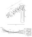
- FIG. 1is a partial perspective view of a diagnostic instrument system in accordance with a preferred embodiment of the present invention
- FIG. 2 ( a )is a partially exploded top perspective view of the diagnostic instrument depicted in FIG. 1;
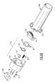
- FIG. 2 ( b )is an exploded rear perspective view of a diagnostic instrument similar to that depicted in FIG. 2 ( a );
- FIG. 3is a side sectioned view of the instrument of FIGS. 1 - 2 ( b );
- FIG. 4is a top sectioned view of the instrument of FIGS. 1-3;
- FIG. 5is a partial ray trace diagram of the optical portion of the instrument of FIG. 1, including a thermal baffle according to a first embodiment of the present invention
- FIG. 6is a partial ray trace diagram of the optical portion of the instrument of FIG. 1, including a thermal baffle according to a second embodiment of the present invention and further including calibration means for the instrument;
- FIG. 7depicts a typical output display indicating portion of a temperature profile according to the diagnostic instrument system of FIG. 1;
- FIG. 8is a display output indicating regions of various temperatures of a predetermined target area
- FIG. 9depicts a digital temperature display for the instrument of FIG. 1;
- FIG. 10is an enlarged front view of the thermal sensor array of the instrument of FIG. 1;
- FIG. 11depicts a view of a target area including an occluded portion
- FIG. 12depicts a relative plot of temperature for the target area of FIG. 11;
- FIG. 13depicts a predicted plot of temperature for the target area of FIG. 11;
- FIG. 14depicts another predicted plot of temperature for the target area of FIG. 11;
- FIG. 15illustrates a display portion for the diagnostic instrument made in accordance with a preferred aspect of the invention
- FIG. 16illustrates the display portion of FIG. 15 indicating the centering of the hottest temperature value
- FIG. 17illustrates a partial plan view of an instrument having a fixed thermal sensor used in conjunction with a scanning mirror assembly
- FIG. 18illustrates an enlarged view of the thermal sensor and scanning mirror of FIG. 17
- FIG. 19illustrates an alternate embodiment of a movable thermal element
- FIG. 20is a side diagrammatic partial view of a diagnostic instrument having a movable optics assembly
- FIG. 21illustrates a predicted plot of temperature using an interpolation technique.
- the following descriptionrelates to certain embodiments of a medical diagnostic instrument system used in conjunction with an otological medical device and particularly for measuring the body core temperature of a patient through interrogation of the tympanic membrane. It will be readily apparent from the following discussion, however, that the concepts detailed herein will find similar application in measuring other medical targets, such as under the armpit, under the tongue, the colon, portions of the skin for skin disorders, tumors, etc, as well as other anatomical areas of interest.
- a portable examination or diagnostic instrument 24includes a tethered electrical/video signal connection 26 with a video monitor 28 or other video peripheral device (not shown), although alternately a wireless connection through RF, IRdA or other means, shown figuratively as 32 , can also be employed.
- the portable examination instrument 24includes an instrument head 36 which is attached, releasably or otherwise, to the top of a hand-grippable battery handle 40 .
- the instrument head 36is shown nearly identically in FIGS. 2 ( a ) and 2 ( b ), except as noted specifically herein, though the hand-grippable handle 40 A shown in FIG. 2 ( b ) is a variation. Similar variations for use with the instant instrument head 36 are contemplated within the scope of the present invention. For example, and rather than using a video monitor, the instrument head could include a portable integral display.
- the instrument head 36includes a detector assembly 42 and an optical assembly 70 which are each disposed within the confines of a housing 50 .
- the housing 50is attached to the hand-grippable handle 40 , 40 A, by conventional means.
- threaded fasteners 53can be used to secure the handle 40 A to the rear side of the housing 50 using threaded holes 52 .
- the detector assembly 42includes an IR element or sensor array 44 having a plurality of miniature infrared sensors 45 , FIG. 10, such as the bolometer array manufactured by TI/Raytheon, which are mounted onto a supporting body 48 .
- a two dimensional 16 ⁇ 16 element arrayis defined, though the parameters thereof can easily be varied depending on the application.
- a single element or a one dimensional arraycan also be utilized based on the inventive concepts of the present invention.
- An enlarged view of an IR sensor array 44 in accordance with the present inventionis depicted in FIG. 10 .
- Each of the individual elements 45 comprising the sensor array 44senses infrared radiation of a portion of a target area, akin to individual pixels of an electronic imager, such as a CCD, and produces an output signal which can be processed through suitable electronics to provide temperature of that sensed portion.
- the optical assembly 70includes a conically shaped aperture stop 60 , which overlays the miniature IR sensor array 44 , as well as an objective lens 61 and a relay lens 63 which focus incoming IR light onto the IR sensor array 44 of the detector assembly 42 .
- the aperture stop 60is mounted by conventional means such as threaded fasteners 65 (FIG. 2 b ) onto the supporting body 48 .
- the aperture stop 60includes a central through opening 64 which provides optical access to the IR sensor array 44 .
- the aperture stop 60is aligned with the IR sensor array 44 and is attached onto the supporting body 48 using fasteners 65 inserted through the holes 66 .
- the housing 50includes a substantially frusto-conical insertion portion 78 which is sized to receive a speculum (not shown) and which can be placed up to a predetermined distance into the ear canal of a patient (not shown) such as through the use of a locator 58 .
- the lenses 61 , 63combine to focus incoming optical energy onto the miniature IR sensor array 44 .
- the objective lens 61is disposed at the distal end of the frusto-conical insertion portion 78 of the housing 50 while the relay lens 63 is placed adjacent the aperture stop 60 .
- the housing 50is attached to the handle 40 , 40 A by screws 53 that thread into the proximal end of the housing at threaded holes 52 , FIG. 2 ( b ).
- the objective lens 61being placed at the distal tip opening of the insertion portion 78 permits a wide field of view in order to “see” the tympanic membrane and to avoid hair, ear wax, and a significant bending portion of the ear canal.
- the locator 58is positioned and shaped to allow the distal end of the insertion portion 78 to be repeatably positioned a predetermined distance within the ear canal, but without contacting the tympanic membrane.
- the relay lens 63permits the detector assembly 42 to be positioned within the instrument head 36 wherein the image obtained by the objective lens 61 can be focused thereupon.
- the locator 58provides repeatability and consistency with regard to alignment, depth of field, and orientation of a thermally imaged target area. This provides an additional advantage. For example, a thermal image can therefore be superimposed or have superimposed thereupon, a corresponding video image of the target area captured by a video otoscope (not shown).
- the above optical assembly 70can be adjusted using a focusing screw 57 inserted through opening 68 in the housing 50 and threaded into the supporting body at hole 51 .
- a focus spring 62provides a biasing force to permit adjustment of the assembly containing the supporting body 48 and aperture stop 60 relative to the housing 50 .
- supporting body 48slides on pins 47 , FIGS. 2 ( b ) and 4 , extending from the interior of the insertion portion 78 .
- the aperture stop 60further limits the amount of energy passing through the optical subassembly 70 from a target area 100 to the IR sensor array 44 .
- An alternate aperture stop 104is illustrated in FIG. 5, the aperture stop being thermally linked directly to the supporting body 48 of the detector assembly 42 , to provide the same temperature of the aperture stop as that of supporting body 48 and IR thermal array 44 given that the aperture stop also emits energy which is detected by the IR sensor array 44 .
- the aperture stops 60 , 104as used in conjunction with the optical subassembly 70 , provide the following benefits.
- the small diameter objective lens 61can be positioned at the distal end of the insertion portion 78 to bypass hair, ear wax, and significant bending of the ear canal and to provide a relatively wide field of view of the target area.
- the provision of an aperture stop for the energy focused on the detector assembly 42 by the relay lens 63insures that the representative pixels of the sensor array 44 see energy emanating only from the target 100 , the aperture stop 60 , 104 , and the relay lens 63 .
- the relay lens 63emits a negligible amount of energy as compared to the target 100 and the aperture stop 60 , 104 .
- the effect of the aperture stop 104 , FIG. 5,is negligible in relation to the signals received by the sensor array 44 in calculating the temperature of the interrogated target area 100 .
- the energy of the aperture stop 60 , FIG. 6,can be accounted for by subtraction as part of calibration of the sensor array 44 , such as described herein.
- a movable target 84such as a diode or other form of calibration element, having a known temperature and emissivity is movably disposed in relation to the optical path 54 to the detector assembly 42 in order to initially calibrate the miniature IR sensor array 44 .
- an optical element 98could be aligned with the target 84 such that either the target 84 and/or the optical element 98 “moves” the target into and out of the optical path 54 to the IR sensor array 44 .
- a temperature measuring element 99such as a thermocouple or thermistor, can be disposed on the supporting body 48 of the detector assembly 42 , the element 99 being capable of measuring the reference temperature of the supporting body 48 to permit calibration of the array 44 .
- one of the pixels 101 of the arraycan be “blinded” to incoming energy from the target to achieve a similar effect. It should be further noted in passing that a temperature measuring element, such as described above, could otherwise be disposed (e.g., on the aperture stop 60 , FIG. 6 ).
- the display output of the IR sensor array 44can be demonstrated to cover various forms.
- the display outputcan take the form of a matrix or grid 106 having individual numeric processed temperature values 108 .
- the displayed temperatures 108can cover a portion of the grid 106 , indicating only those temperature values exceeding a specific threshold temperature, as shown, or all of the sensor processed output values can be displayed.
- the display output 110can be arranged into a predetermined format.
- output signals of the individual sensorscan be segregated into different visually perceivable forms, such as textures or false colors, such as first, second, third, and fourth ranges 112 , 114 , 116 , 118 , respectively, leading the user to identify a “hot” spot 122 .
- any visually perceivable formcould be utilized in order to provide contrasts between ranges of temperatures as detected by the IR sensor array 44 .
- a simplified display output 126can include merely the hottest temperature in the field of view as a single temperature value, 130 , such as shown in FIG. 9 . It will be readily apparent that other forms of representation can be contemplated by one of sufficient skill in the field. There may be situations, as described herein below, in which the displayed temperature is not the hottest temperature of the target area. In those instances, the display output 126 can also include an indicator 134 which informs the user that the displayed temperature 130 is estimated.
- the detection of the hottest temperature of a medical target areaindicates body core temperature given that the arteries in the tympanic membrane are closely tied to the hypothalamus, the temperature regulator of the human body.
- Identification of body core temperature as described herein through the use of an IR sensor arrayprovides an improvement in accuracy and reliability in the field of thermometry.
- the pulse rate of the patientcan also be determined due to flow of hot blood into the arteries.
- the transient effectcan be included in each of the above display representations or separately to indicate this value.
- the hottest temperaturemight not be directly discernible based on either the presence of an obstruction or that the hottest temperature of the target area is not in the immediate field of view of the IR sensor array 44 .
- a portion 129 of an overall target area 120in this case a portion of the tympanic membrane 121
- phantom line 124such as by ear wax, an abscess, ear canal wall etc., which blocks the hottest spot 128 (that is the spot having the highest temperature) from view.
- the processing electronics provided in the detector assembly 42 , FIG. 3,includes a microprocessor (not shown) having sufficient memory for storing the calibrated values of the output signals of each of the IR sensors 45 , FIG. 10, of the IR sensor array 44 , FIG. 3 .
- a corresponding temperature profile 132would be detected by the present sensor array.
- the obstructed portion of the temperature profile 132would be correctly represented by the profile depicted as 136 including the hottest spot, depicted as 128 in FIG. 11, and indicated as 140 in FIG. 12, if the obstruction did not exist.
- a predetermined number of points 144 , 145 , 146 along the profile 132are processed due to the increase in temperature.
- a highest pointis then extrapolated by curve fitting through the points 144 , 145 , 146 to determine an estimated hottest spot 140 a , FIG. 14 through fitted curve 136 a , FIG. 14 .
- a hottest temperature of a target areacan also be interpolated through curve fitting, for example, if the hottest spot is “between” pixels of the sensor array 44 , FIG. 10, such as fitting an appropriate curve or temperature profile 157 through a number of predetermined temperature points 152 and interpolating an estimated hottest temperature 158 .
- the instrumentincludes an indicator 150 connected in relation to the processing electronics of the device, the indicator having a set of directional guides 154 arranged in 90 degree intervals about a center guide 156 . It should be readily apparent that the above description is exemplary as any varied number of directional guides can be suitably placed along a periphery. As the instrument is used, the hottest temperature in the field of view of the IR sensor array is determined and the locale of the hottest temperature is indicated by a corresponding directional guide 154 .
- the guide 154aids the user in adjusting the field of view of the instrument by moving the instrument in the direction indicated by the indicator 150 .
- the directional guide 154will shift until the hottest temperature value is eventually located in the center guide 156 , as shown in FIG. 16, thereby indicating that the hottest temperature value has been centered in the field of view.
- a new hottest temperaturewill be located, the value of this temperature being stored into memory and compared using the processing electronics during use as the field of view is changed.
- a single LEDcould be provided. In this instance, the LED could provide the user with a visual indication when the hottest temperature has been detected by the microprocessor.
- indicating meanscould be employed to notify the user that the hottest temperature of a target area has been located or identified, such as, for example, an audio signal or tactile feedback, such as a vibrational signal.
- an examination instrument 160can utilize a single sensor or one dimensional IR sensor array 166 in conjunction with a movable mirror 170 to scan the target area of interest, as defined by 176 in two dimensions.
- the mirror 170is retained within an instrument housing 164 and is made rotatable, for example, as supported within a frame 180 having rotatable sections 184 , 188 to provide rotation as indicated by arrows 189 about respective axes 187 to define a scan field 190 of the target area.
- An alternate micro-machined sensor support 192in this case for a single IR sensor 166 , is illustrated in FIG.
- the supportbeing translatable along orthogonal axes 196 , 198 .
- mirror 170 , FIG. 17is stationary and the single IR sensor 166 translates in the two orthogonal directions to capture each portion of field 190 .
- the sensor 166can be calibrated using a movable or dedicated reference temperature element (not shown), or the other methods described in the preceding embodiment.
- FIG. 20a further embodiment partially depicts an apparatus 200 including a single IR sensor 202 disposed within a housing 203 .
- the sensor 202 or linear (one-dimensional) sensor arraycan be translated along orthogonal directions 208 , 210 with respect to a target area 212 through a lens or aperture 204 .
- the aperture 204 or lenscan alternately be moved (i.e. translated) in a similar manner to effectively scan a thermal image of the target area 212 .
- a similar IR sensor array assemblycould be incorporated into an endoscope or laparoscope in order to examine a polyp or the appendix.
- a sensor assembly as describedcould also be included in a borescope for examining the interior of an industrial target, such as the interior of an aircraft engine.
Landscapes
- Physics & Mathematics (AREA)
- General Physics & Mathematics (AREA)
- Spectroscopy & Molecular Physics (AREA)
- Engineering & Computer Science (AREA)
- Human Computer Interaction (AREA)
- Measuring And Recording Apparatus For Diagnosis (AREA)
- Radiation Pyrometers (AREA)
Abstract
Description
Claims (137)
Priority Applications (6)
| Application Number | Priority Date | Filing Date | Title |
|---|---|---|---|
| US09/825,478US6631287B2 (en) | 2001-04-03 | 2001-04-03 | Infrared thermometer |
| CA002442937ACA2442937A1 (en) | 2001-04-03 | 2002-04-02 | Infrared thermometer |
| AU2002256070AAU2002256070B2 (en) | 2001-04-03 | 2002-04-02 | Infrared thermometer |
| EP02725511AEP1373846A1 (en) | 2001-04-03 | 2002-04-02 | Infrared thermometer |
| JP2002579753AJP2004528085A (en) | 2001-04-03 | 2002-04-02 | Infrared thermometer |
| PCT/US2002/010540WO2002082029A1 (en) | 2001-04-03 | 2002-04-02 | Infrared thermometer |
Applications Claiming Priority (1)
| Application Number | Priority Date | Filing Date | Title |
|---|---|---|---|
| US09/825,478US6631287B2 (en) | 2001-04-03 | 2001-04-03 | Infrared thermometer |
Publications (2)
| Publication Number | Publication Date |
|---|---|
| US20020143257A1 US20020143257A1 (en) | 2002-10-03 |
| US6631287B2true US6631287B2 (en) | 2003-10-07 |
Family
ID=25244093
Family Applications (1)
| Application Number | Title | Priority Date | Filing Date |
|---|---|---|---|
| US09/825,478Expired - LifetimeUS6631287B2 (en) | 2001-04-03 | 2001-04-03 | Infrared thermometer |
Country Status (6)
| Country | Link |
|---|---|
| US (1) | US6631287B2 (en) |
| EP (1) | EP1373846A1 (en) |
| JP (1) | JP2004528085A (en) |
| AU (1) | AU2002256070B2 (en) |
| CA (1) | CA2442937A1 (en) |
| WO (1) | WO2002082029A1 (en) |
Cited By (40)
| Publication number | Priority date | Publication date | Assignee | Title |
|---|---|---|---|---|
| US20030171655A1 (en)* | 2002-03-08 | 2003-09-11 | Newman Richard W. | Combination otoscope |
| US6709154B1 (en)* | 1998-09-16 | 2004-03-23 | Braun Gmbh | Radiation thermometer and radiation sensor with several sensor elements, method for determining temperature |
| US20040133108A1 (en)* | 2002-12-06 | 2004-07-08 | Jan Lewandowski | Ultrasonic detection of ear disorders |
| US20040165646A1 (en)* | 2003-02-20 | 2004-08-26 | Shidemantle Jack P. | Digitally modified resistive output for a temperature sensor |
| US20040254472A1 (en)* | 2003-05-27 | 2004-12-16 | Cardiowave, Inc. | Methods and apparatus for a remote, noninvasive technique to detect core body temperature in a subject via thermal imaging |
| US20050018749A1 (en)* | 2001-06-04 | 2005-01-27 | Omron Corporation | Infrared clinical thermometer and temperature state estimation method, information notification method, and measurement operation method thereof |
| US20050039513A1 (en)* | 2003-08-22 | 2005-02-24 | Mario Fabris | Method and apparatus for aligning equipment in a steel mill |
| US20050084374A1 (en)* | 2003-10-17 | 2005-04-21 | Booe James M.Jr. | Shock-absorbing propeller assembly |
| US20050207470A1 (en)* | 2004-01-26 | 2005-09-22 | Bennett Timothy J | Focusing thermometer |
| US20070217478A1 (en)* | 2004-05-17 | 2007-09-20 | Anders Carlsson | Measuring device |
| US20070261494A1 (en)* | 2006-04-28 | 2007-11-15 | Biomec, Inc. | Ultrasonic transducer devices and detection apparatus |
| US20070268954A1 (en)* | 2006-05-19 | 2007-11-22 | Sherwood Services Ag | Portable test apparatus for radiation-sensing thermometer |
| US20080246625A1 (en)* | 2007-04-09 | 2008-10-09 | Avita Corporation | Non-contact temperature-measuring device and the method thereof |
| US7507019B2 (en) | 2006-05-19 | 2009-03-24 | Covidien Ag | Thermometer calibration |
| US20090182526A1 (en)* | 2008-01-16 | 2009-07-16 | Welch-Allyn, Inc. | Guiding ir temperature measuring device with probe cover |
| US20090257469A1 (en)* | 2008-04-09 | 2009-10-15 | Jones Mike N | Infrared thermometer |
| US20100069752A1 (en)* | 2002-12-06 | 2010-03-18 | Otosonics, Inc. | Ultrasonic detection of ear disorders |
| US20100265986A1 (en)* | 2009-04-20 | 2010-10-21 | Welch Allyn, Inc. | Calibrated assembly for ir thermometer apparatus |
| US20100284436A1 (en)* | 2009-05-05 | 2010-11-11 | Welch Allyn, Inc. | Ir thermometer thermal isolation tip assembly |
| US8197132B2 (en) | 2006-10-06 | 2012-06-12 | Covidien Ag | Electronic thermometer with selectable modes |
| US8274273B2 (en) | 2008-03-07 | 2012-09-25 | Milwaukee Electric Tool Corporation | Test and measurement device with a pistol-grip handle |
| US8317776B2 (en) | 2007-12-18 | 2012-11-27 | The Invention Science Fund I, Llc | Circulatory monitoring systems and methods |
| US8409132B2 (en) | 2007-12-18 | 2013-04-02 | The Invention Science Fund I, Llc | Treatment indications informed by a priori implant information |
| US8636670B2 (en) | 2008-05-13 | 2014-01-28 | The Invention Science Fund I, Llc | Circulatory monitoring systems and methods |
| US20140321501A1 (en)* | 2013-04-24 | 2014-10-30 | Progress Rail Services Corporation | Hot bearing detection system and method |
| US9307912B2 (en) | 2012-08-08 | 2016-04-12 | Welch Allyn, Inc. | Temperature measurement system |
| US20170079532A1 (en)* | 2015-09-23 | 2017-03-23 | Honeywell International Inc. | Body core temperature measurement |
| US20170082496A1 (en)* | 2015-09-23 | 2017-03-23 | Honeywell International Inc. | Body core temperature measurement |
| US20170211993A1 (en)* | 2016-01-21 | 2017-07-27 | Honeywell International Inc. | Body core temperature measurement |
| US9857228B2 (en) | 2014-03-25 | 2018-01-02 | Rosemount Inc. | Process conduit anomaly detection using thermal imaging |
| US10638093B2 (en) | 2013-09-26 | 2020-04-28 | Rosemount Inc. | Wireless industrial process field device with imaging |
| US10823592B2 (en) | 2013-09-26 | 2020-11-03 | Rosemount Inc. | Process device with process variable measurement using image capture device |
| US10914635B2 (en) | 2014-09-29 | 2021-02-09 | Rosemount Inc. | Wireless industrial process monitor |
| US11076113B2 (en) | 2013-09-26 | 2021-07-27 | Rosemount Inc. | Industrial process diagnostics using infrared thermal sensing |
| US11166623B2 (en) | 2019-04-23 | 2021-11-09 | Arthrex, Inc. | Field stop fluorescent indicator system and method |
| US11213252B2 (en) | 2017-10-20 | 2022-01-04 | Starkey Laboratories, Inc. | Devices and sensing methods for measuring temperature from an ear |
| US11395622B2 (en) | 2015-11-06 | 2022-07-26 | Podimetrics, Inc. | Footwear system for ulcer or pre-ulcer detection |
| US11771363B2 (en) | 2018-10-15 | 2023-10-03 | Podimetrics, Inc. | Ipsilateral ulcer and pre-ulcer detection method and apparatus |
| US11857303B2 (en) | 2021-12-06 | 2024-01-02 | Podimetrics, Inc. | Apparatus and method of measuring blood flow in the foot |
| US12174111B2 (en) | 2019-10-07 | 2024-12-24 | Innopix, Inc. | Spectral imaging and analysis for remote and noninvasive detection of plant responses to herbicide treatments |
Families Citing this family (42)
| Publication number | Priority date | Publication date | Assignee | Title |
|---|---|---|---|---|
| US7308314B2 (en)* | 2002-06-06 | 2007-12-11 | Advanced Medical Electronics | Method and apparatus for sensory substitution, vision prosthesis, or low-vision enhancement utilizing thermal sensing |
| EP1618740A2 (en)* | 2003-04-25 | 2006-01-25 | Land Instruments International Limited | Thermal imaging system and method |
| DE102004027443B3 (en)* | 2004-06-04 | 2005-07-21 | Dräger Safety AG & Co. KGaA | Measurement system for contactless body core temperature determination has evaluation unit for evaluating infrared signal that selects maximum value in matrix, computer unit for computing core temperature from selected maximum value |
| US7507025B2 (en)* | 2005-08-29 | 2009-03-24 | Wayne R Lumpkin | Infrared thermometer with an axially actuated temperature sensor |
| US7275867B2 (en)* | 2005-12-01 | 2007-10-02 | Oriental System Technology Inc. | Probe assembly of infrared thermometer |
| CA2538940A1 (en)* | 2006-03-03 | 2006-06-22 | James W. Haslett | Bandage with sensors |
| RU2466676C2 (en)* | 2007-03-15 | 2012-11-20 | Конинклейке Филипс Электроникс Н.В. | Methods and devices for core temperature measurement |
| US20100088060A1 (en)* | 2007-03-15 | 2010-04-08 | Koninklijke Philips Electronics N.V. | Apparatuses and methods for measuring and controlling thermal insulation |
| WO2008110948A2 (en)* | 2007-03-15 | 2008-09-18 | Koninklijke Philips Electronics N.V. | Methods and devices for measuring core body temperature |
| US20090204008A1 (en)* | 2008-02-08 | 2009-08-13 | Daniel Beilin | Whole body infrared thermography systems and methods |
| US8457922B2 (en)* | 2009-03-27 | 2013-06-04 | Fluke Corporation | System and method for determining accuracy of an infrared thermometer measurement |
| JP5446443B2 (en)* | 2009-05-15 | 2014-03-19 | 日産自動車株式会社 | Heart rate measuring apparatus and heart rate measuring method |
| US8306774B2 (en)* | 2009-11-02 | 2012-11-06 | Quinn David E | Thermometer for determining the temperature of an animal's ear drum and method of using same |
| US9261407B2 (en)* | 2009-11-02 | 2016-02-16 | Eric M. Lawson | Thermometer for determining the temperature of an animal's ear drum and method of using the same |
| US8374683B2 (en)* | 2009-12-30 | 2013-02-12 | Ray D. Stone | Medical instrument with probe, probe cover, and methods of using the same |
| US9706138B2 (en) | 2010-04-23 | 2017-07-11 | Flir Systems, Inc. | Hybrid infrared sensor array having heterogeneous infrared sensors |
| US20120083710A1 (en) | 2010-09-30 | 2012-04-05 | Medism Ltd. | Ergonomic hand-held thermometer |
| WO2012067282A1 (en)* | 2010-11-17 | 2012-05-24 | (주)이지템 | Mobile device and method for measuring temperature of thermal picture including body temperature |
| CN102162752B (en)* | 2010-12-14 | 2012-11-21 | 天津理工大学 | Array infrared thermometer |
| WO2013049474A1 (en)* | 2011-09-29 | 2013-04-04 | Covidien Lp | Electronic thermometer with image sensor and display |
| DE102011121020B3 (en)* | 2011-12-13 | 2013-01-31 | Jan Dreyer | Subcutaneous vessel representation device for contactless location of warm skin region on surface, measures/compares temperature of larger measuring range and smaller measuring range enclosed by larger measuring range in circular form |
| JP2013202260A (en)* | 2012-03-29 | 2013-10-07 | Sony Corp | Information processing apparatus, method for processing information, and computer program |
| CN108245138B (en) | 2012-04-02 | 2020-11-24 | 珀迪迈垂克斯公司 | Device for monitoring a patient's foot |
| CN205157051U (en)* | 2012-11-26 | 2016-04-13 | 菲力尔系统公司 | Infrared sensor package |
| MX363569B (en)* | 2013-02-04 | 2019-03-27 | Helen Of Troy Ltd | Ear inspection device and method of determining a condition of a subject's ear. |
| US9677950B2 (en)* | 2013-03-14 | 2017-06-13 | Robert Bosch Gmbh | Portable device with temperature sensing |
| JP2017501844A (en)* | 2014-01-10 | 2017-01-19 | マーシオ マーク アブリュー | Device for measuring the infrared output of an Abreu brain thermal tunnel |
| US9375149B2 (en) | 2014-03-18 | 2016-06-28 | Welch Allyn, Inc. | Noncontact thermometry systems and methods |
| JP6689204B2 (en) | 2014-03-21 | 2020-04-28 | ポディメトリクス インコーポレイテッドPodimetrics, Inc. | Method and device for monitoring foot inflammation |
| WO2017006768A1 (en)* | 2015-07-09 | 2017-01-12 | Kddi株式会社 | Pulse measuring device, wearable terminal, and pulse measuring method |
| JP6636743B2 (en)* | 2015-08-03 | 2020-01-29 | Kddi株式会社 | Pulse measuring device and pulse measuring method |
| US10184844B2 (en)* | 2015-12-31 | 2019-01-22 | Withings | Compact home thermometer |
| JP6557611B2 (en) | 2016-01-26 | 2019-08-07 | Kddi株式会社 | Pulse measuring device |
| JP6509751B2 (en) | 2016-01-28 | 2019-05-08 | Kddi株式会社 | Pulse measurement device |
| US10506926B2 (en) | 2017-02-18 | 2019-12-17 | Arc Devices Limited | Multi-vital sign detector in an electronic medical records system |
| US10492684B2 (en) | 2017-02-21 | 2019-12-03 | Arc Devices Limited | Multi-vital-sign smartphone system in an electronic medical records system |
| US10602987B2 (en) | 2017-08-10 | 2020-03-31 | Arc Devices Limited | Multi-vital-sign smartphone system in an electronic medical records system |
| US10485431B1 (en) | 2018-05-21 | 2019-11-26 | ARC Devices Ltd. | Glucose multi-vital-sign system in an electronic medical records system |
| DE102018218726A1 (en)* | 2018-10-31 | 2020-04-30 | Robert Bosch Gmbh | Method for operating a thermal imaging camera and thermal imaging camera |
| CN113253439A (en)* | 2020-02-10 | 2021-08-13 | 科沃斯机器人股份有限公司 | Optical flow module and robot |
| WO2021247300A1 (en) | 2020-06-01 | 2021-12-09 | Arc Devices Limited | Apparatus and methods for measuring blood pressure and other vital signs via a finger |
| CN111707380A (en)* | 2020-07-10 | 2020-09-25 | 浙江荣胜工具有限公司 | A forehead thermometer that displays different colors according to the detected temperature and its control circuit |
Citations (52)
| Publication number | Priority date | Publication date | Assignee | Title |
|---|---|---|---|---|
| US4036211A (en)* | 1975-04-08 | 1977-07-19 | United States Surgical Corporation | Temperature, pulse and respiration detection apparatus |
| US4054057A (en) | 1976-03-01 | 1977-10-18 | Diatek, Inc. | Temperature sensing probe and disposable cover therefor |
| US4365307A (en) | 1981-02-25 | 1982-12-21 | Sumitomo Kinzoku Kogyo Kabushiki Gaisha | Temperature pattern measuring device |
| US4383271A (en) | 1980-05-22 | 1983-05-10 | Barr & Stroud Limited | Thermal imager |
| US4413324A (en) | 1981-02-25 | 1983-11-01 | Sumitomo Kinzoku Kogyo Kabushiki Kaisha | Temperature pattern measuring method and a device therefor |
| US4450479A (en) | 1981-04-29 | 1984-05-22 | U.S. Philips Corporation | Thermal imaging apparatus |
| US4494550A (en)* | 1981-01-12 | 1985-01-22 | Vladimir Blazek | Measuring apparatus for the non-invasive detection of venous and arterial blood flow and drainage disorders |
| US4594507A (en) | 1983-10-14 | 1986-06-10 | The Secretary Of State For Defence In Her Britannic Majesty's Government Of The United Kingdom Of Great Britain And Northern Ireland | Thermal imager |
| WO1986006136A1 (en) | 1985-04-12 | 1986-10-23 | Edwin Ott | Convertible diesel engine for aircraft or other applications with optimalized high output, high supercharge and total energy utilization |
| US4700708A (en) | 1982-09-02 | 1987-10-20 | Nellcor Incorporated | Calibrated optical oximeter probe |
| US4737917A (en) | 1986-07-15 | 1988-04-12 | Emhart Industries, Inc. | Method and apparatus for generating isotherms in a forehearth temperature control system |
| US4754139A (en) | 1986-04-10 | 1988-06-28 | Aerojet-General Corporation | Uncooled high resolution infrared imaging plane |
| US4784149A (en)* | 1986-01-13 | 1988-11-15 | Optical Sensors, Inc. | Infrared thermometer with automatic calibration |
| US4806761A (en) | 1985-04-08 | 1989-02-21 | Irvine Sensors Corporation | Thermal imager incorporating electronics module having focal plane sensor mosaic |
| US4993424A (en) | 1989-12-04 | 1991-02-19 | Diatek, Incorporated | Infrared medical thermometer |
| US5018872A (en) | 1988-11-01 | 1991-05-28 | Diatek, Inc. | Probe assembly for infrared thermometer |
| US5086220A (en) | 1991-02-05 | 1992-02-04 | The Babcock & Wilcox Company | Radiation imaging fiber optic temperature distribution monitor |
| US5091646A (en) | 1990-05-29 | 1992-02-25 | Kollmorgen Corporation | Integrated thermal imaging system |
| US5127742A (en)* | 1991-04-19 | 1992-07-07 | Thermoscan Inc. | Apparatus and method for temperature measurement by radiation |
| US5272340A (en) | 1992-09-29 | 1993-12-21 | Amara, Inc. | Infrared imaging system for simultaneous generation of temperature, emissivity and fluorescence images |
| US5274489A (en) | 1991-02-15 | 1993-12-28 | Gec-Marconi Limited | Thermal imager systems |
| US5274235A (en) | 1990-05-29 | 1993-12-28 | Kollmorgen Corp | Integrated imaging system |
| USRE34507E (en) | 1988-04-12 | 1994-01-11 | Citizen Watch Co., Ltd. | Radiation clinical thermometer |
| US5289006A (en) | 1991-09-27 | 1994-02-22 | Allied Signal Inc. | Thermal imaging apparatus |
| US5293877A (en)* | 1990-12-12 | 1994-03-15 | Sherwood Ims, Inc. | Body temperature thermometer and method fo measuring human body temperature utilizing calibration mapping |
| US5368392A (en) | 1993-09-17 | 1994-11-29 | Omega Engineering, Inc. | Method and apparatus for measuring temperature using infrared techniques |
| US5420428A (en) | 1993-05-05 | 1995-05-30 | Radiant Technologies, Inc. | Infra-red sensing array |
| US5438199A (en) | 1994-09-06 | 1995-08-01 | Alliedsignal Inc. | Thermal imaging apparatus with bias modulation |
| US5469855A (en) | 1991-03-08 | 1995-11-28 | Exergen Corporation | Continuous temperature monitor |
| US5530246A (en) | 1987-04-13 | 1996-06-25 | British Aerospace Plc | Viewing system |
| US5561295A (en) | 1994-07-29 | 1996-10-01 | Litton Systems, Inc. | Infrared-responsive photoconductive array and method of making |
| US5626147A (en) | 1993-11-23 | 1997-05-06 | Thermoscan, Inc. | Tympanic thermometer |
| US5632555A (en) | 1994-09-09 | 1997-05-27 | Diatek, L.P. | Medical thermometer |
| US5645349A (en)* | 1994-01-10 | 1997-07-08 | Thermoscan Inc. | Noncontact active temperature sensor |
| US5653537A (en) | 1995-03-17 | 1997-08-05 | Ircon, Inc. | Non-contacting infrared temperature thermometer detector apparatus |
| GB2311368A (en) | 1996-03-22 | 1997-09-24 | Gary Rogers | System for detecting malagnancies |
| US5686779A (en) | 1995-03-01 | 1997-11-11 | The United States Of America As Represented By The Secretary Of The Army | High sensitivity temperature sensor and sensor array |
| US5729019A (en) | 1995-12-29 | 1998-03-17 | Honeywell Inc. | Split field-of-view uncooled infrared sensor |
| US5727880A (en) | 1993-09-17 | 1998-03-17 | Omega Engineering, Inc. | Method and apparatus for measuring temperature using infrared techniques |
| US5747863A (en) | 1996-07-08 | 1998-05-05 | Nikon Corporation | Infrared solid-state image pickup device and infrared solid-state image pickup apparatus equipped with this device |
| US5790586A (en) | 1993-09-30 | 1998-08-04 | Amorphous Materials, Inc. | Method and apparatus for simultaneously illuminating, viewing and measuring the temperature of a body |
| US5820264A (en) | 1996-03-25 | 1998-10-13 | Oriental System Technology, Inc. | Tympanic thermometer arrangement |
| US5823678A (en) | 1993-09-17 | 1998-10-20 | Omega Engineering, Inc. | Light source aiming system and method for hand-held temperature measuring unit |
| EP0875197A1 (en) | 1996-11-14 | 1998-11-04 | Citizen Watch Co. Ltd. | Radiation thermometer |
| US5847832A (en) | 1996-03-15 | 1998-12-08 | Hughes Aircraft Company | Moire topographic measurement |
| US5902044A (en) | 1997-06-27 | 1999-05-11 | International Business Machines Corporation | Integrated hot spot detector for design, analysis, and control |
| US6011891A (en) | 1996-04-26 | 2000-01-04 | Katzir; Abraham | Infrared-transmitting-fiber-optic-cable-based device for non-contact thermometry |
| DE19842403A1 (en) | 1998-09-16 | 2000-03-23 | Braun Gmbh | Radiation thermometer with several sensor elements for detecting infrared radiation in different areas; has radiation sensor with several infrared sensor elements |
| WO2000016047A1 (en)* | 1998-09-16 | 2000-03-23 | Braun Gmbh | Method for determining temperature, radiation thermometer with several infrared sensor elements |
| DE19857145A1 (en) | 1998-09-16 | 2000-03-23 | Braun Gmbh | Taking e.g. body temperatures from the auditory canal, using infrared radiation thermometer array, selects the greatest signal delivered, corresponding to observation of eardrum temperature |
| WO2000016046A2 (en) | 1998-09-15 | 2000-03-23 | Jonathan Gerlitz | Infrared ear thermometer |
| JP2001054505A (en)* | 1999-08-19 | 2001-02-27 | Matsushita Electric Ind Co Ltd | Ear hole thermometer |
Family Cites Families (1)
| Publication number | Priority date | Publication date | Assignee | Title |
|---|---|---|---|---|
| US4797840A (en)* | 1985-04-17 | 1989-01-10 | Thermoscan Inc. | Infrared electronic thermometer and method for measuring temperature |
- 2001
- 2001-04-03USUS09/825,478patent/US6631287B2/ennot_activeExpired - Lifetime
- 2002
- 2002-04-02JPJP2002579753Apatent/JP2004528085A/enactivePending
- 2002-04-02CACA002442937Apatent/CA2442937A1/ennot_activeAbandoned
- 2002-04-02EPEP02725511Apatent/EP1373846A1/ennot_activeWithdrawn
- 2002-04-02AUAU2002256070Apatent/AU2002256070B2/ennot_activeCeased
- 2002-04-02WOPCT/US2002/010540patent/WO2002082029A1/enactiveApplication Filing
Patent Citations (56)
| Publication number | Priority date | Publication date | Assignee | Title |
|---|---|---|---|---|
| US4036211A (en)* | 1975-04-08 | 1977-07-19 | United States Surgical Corporation | Temperature, pulse and respiration detection apparatus |
| US4054057A (en) | 1976-03-01 | 1977-10-18 | Diatek, Inc. | Temperature sensing probe and disposable cover therefor |
| US4383271A (en) | 1980-05-22 | 1983-05-10 | Barr & Stroud Limited | Thermal imager |
| US4494550A (en)* | 1981-01-12 | 1985-01-22 | Vladimir Blazek | Measuring apparatus for the non-invasive detection of venous and arterial blood flow and drainage disorders |
| US4365307A (en) | 1981-02-25 | 1982-12-21 | Sumitomo Kinzoku Kogyo Kabushiki Gaisha | Temperature pattern measuring device |
| US4413324A (en) | 1981-02-25 | 1983-11-01 | Sumitomo Kinzoku Kogyo Kabushiki Kaisha | Temperature pattern measuring method and a device therefor |
| US4450479A (en) | 1981-04-29 | 1984-05-22 | U.S. Philips Corporation | Thermal imaging apparatus |
| US4700708A (en) | 1982-09-02 | 1987-10-20 | Nellcor Incorporated | Calibrated optical oximeter probe |
| US4594507A (en) | 1983-10-14 | 1986-06-10 | The Secretary Of State For Defence In Her Britannic Majesty's Government Of The United Kingdom Of Great Britain And Northern Ireland | Thermal imager |
| US4806761A (en) | 1985-04-08 | 1989-02-21 | Irvine Sensors Corporation | Thermal imager incorporating electronics module having focal plane sensor mosaic |
| WO1986006136A1 (en) | 1985-04-12 | 1986-10-23 | Edwin Ott | Convertible diesel engine for aircraft or other applications with optimalized high output, high supercharge and total energy utilization |
| US4784149A (en)* | 1986-01-13 | 1988-11-15 | Optical Sensors, Inc. | Infrared thermometer with automatic calibration |
| US4754139A (en) | 1986-04-10 | 1988-06-28 | Aerojet-General Corporation | Uncooled high resolution infrared imaging plane |
| US4737917A (en) | 1986-07-15 | 1988-04-12 | Emhart Industries, Inc. | Method and apparatus for generating isotherms in a forehearth temperature control system |
| US5530246A (en) | 1987-04-13 | 1996-06-25 | British Aerospace Plc | Viewing system |
| USRE34507E (en) | 1988-04-12 | 1994-01-11 | Citizen Watch Co., Ltd. | Radiation clinical thermometer |
| US5018872A (en) | 1988-11-01 | 1991-05-28 | Diatek, Inc. | Probe assembly for infrared thermometer |
| US4993424A (en) | 1989-12-04 | 1991-02-19 | Diatek, Incorporated | Infrared medical thermometer |
| US5274235A (en) | 1990-05-29 | 1993-12-28 | Kollmorgen Corp | Integrated imaging system |
| US5091646A (en) | 1990-05-29 | 1992-02-25 | Kollmorgen Corporation | Integrated thermal imaging system |
| US5293877A (en)* | 1990-12-12 | 1994-03-15 | Sherwood Ims, Inc. | Body temperature thermometer and method fo measuring human body temperature utilizing calibration mapping |
| US5086220A (en) | 1991-02-05 | 1992-02-04 | The Babcock & Wilcox Company | Radiation imaging fiber optic temperature distribution monitor |
| US5274489A (en) | 1991-02-15 | 1993-12-28 | Gec-Marconi Limited | Thermal imager systems |
| US5469855A (en) | 1991-03-08 | 1995-11-28 | Exergen Corporation | Continuous temperature monitor |
| US5127742A (en)* | 1991-04-19 | 1992-07-07 | Thermoscan Inc. | Apparatus and method for temperature measurement by radiation |
| US5289006A (en) | 1991-09-27 | 1994-02-22 | Allied Signal Inc. | Thermal imaging apparatus |
| US5272340A (en) | 1992-09-29 | 1993-12-21 | Amara, Inc. | Infrared imaging system for simultaneous generation of temperature, emissivity and fluorescence images |
| US5420428A (en) | 1993-05-05 | 1995-05-30 | Radiant Technologies, Inc. | Infra-red sensing array |
| US5524984A (en) | 1993-09-17 | 1996-06-11 | Hollander; Milton B. | Method and apparatus for measuring temperature using infared techniques |
| US5368392A (en) | 1993-09-17 | 1994-11-29 | Omega Engineering, Inc. | Method and apparatus for measuring temperature using infrared techniques |
| US5524984C1 (en) | 1993-09-17 | 2002-05-14 | Omega Engineering | Method and apparatus for measuring temperature using infrared techniques |
| US5368392B1 (en) | 1993-09-17 | 1998-11-03 | Omega Engineering | Method and apparatus for measuring temperature using infrared techniques |
| US5727880A (en) | 1993-09-17 | 1998-03-17 | Omega Engineering, Inc. | Method and apparatus for measuring temperature using infrared techniques |
| US5823678A (en) | 1993-09-17 | 1998-10-20 | Omega Engineering, Inc. | Light source aiming system and method for hand-held temperature measuring unit |
| US5790586A (en) | 1993-09-30 | 1998-08-04 | Amorphous Materials, Inc. | Method and apparatus for simultaneously illuminating, viewing and measuring the temperature of a body |
| US5626147A (en) | 1993-11-23 | 1997-05-06 | Thermoscan, Inc. | Tympanic thermometer |
| US5645349A (en)* | 1994-01-10 | 1997-07-08 | Thermoscan Inc. | Noncontact active temperature sensor |
| US5561295A (en) | 1994-07-29 | 1996-10-01 | Litton Systems, Inc. | Infrared-responsive photoconductive array and method of making |
| US5438199A (en) | 1994-09-06 | 1995-08-01 | Alliedsignal Inc. | Thermal imaging apparatus with bias modulation |
| US5632555A (en) | 1994-09-09 | 1997-05-27 | Diatek, L.P. | Medical thermometer |
| US5686779A (en) | 1995-03-01 | 1997-11-11 | The United States Of America As Represented By The Secretary Of The Army | High sensitivity temperature sensor and sensor array |
| US5653537A (en) | 1995-03-17 | 1997-08-05 | Ircon, Inc. | Non-contacting infrared temperature thermometer detector apparatus |
| US5729019A (en) | 1995-12-29 | 1998-03-17 | Honeywell Inc. | Split field-of-view uncooled infrared sensor |
| US5847832A (en) | 1996-03-15 | 1998-12-08 | Hughes Aircraft Company | Moire topographic measurement |
| GB2311368A (en) | 1996-03-22 | 1997-09-24 | Gary Rogers | System for detecting malagnancies |
| US5820264A (en) | 1996-03-25 | 1998-10-13 | Oriental System Technology, Inc. | Tympanic thermometer arrangement |
| US6272375B1 (en) | 1996-04-26 | 2001-08-07 | Abraham Katzir | Mid infrared transmitting fiber optic based otoscope for non contact tympanic membrane thermometry |
| US6011891A (en) | 1996-04-26 | 2000-01-04 | Katzir; Abraham | Infrared-transmitting-fiber-optic-cable-based device for non-contact thermometry |
| US5747863A (en) | 1996-07-08 | 1998-05-05 | Nikon Corporation | Infrared solid-state image pickup device and infrared solid-state image pickup apparatus equipped with this device |
| EP0875197A1 (en) | 1996-11-14 | 1998-11-04 | Citizen Watch Co. Ltd. | Radiation thermometer |
| US5902044A (en) | 1997-06-27 | 1999-05-11 | International Business Machines Corporation | Integrated hot spot detector for design, analysis, and control |
| WO2000016046A2 (en) | 1998-09-15 | 2000-03-23 | Jonathan Gerlitz | Infrared ear thermometer |
| WO2000016047A1 (en)* | 1998-09-16 | 2000-03-23 | Braun Gmbh | Method for determining temperature, radiation thermometer with several infrared sensor elements |
| DE19857145A1 (en) | 1998-09-16 | 2000-03-23 | Braun Gmbh | Taking e.g. body temperatures from the auditory canal, using infrared radiation thermometer array, selects the greatest signal delivered, corresponding to observation of eardrum temperature |
| DE19842403A1 (en) | 1998-09-16 | 2000-03-23 | Braun Gmbh | Radiation thermometer with several sensor elements for detecting infrared radiation in different areas; has radiation sensor with several infrared sensor elements |
| JP2001054505A (en)* | 1999-08-19 | 2001-02-27 | Matsushita Electric Ind Co Ltd | Ear hole thermometer |
Cited By (68)
| Publication number | Priority date | Publication date | Assignee | Title |
|---|---|---|---|---|
| US6709154B1 (en)* | 1998-09-16 | 2004-03-23 | Braun Gmbh | Radiation thermometer and radiation sensor with several sensor elements, method for determining temperature |
| US7329044B2 (en)* | 2001-06-04 | 2008-02-12 | Omron Healthcare Co., Ltd. | Infrared clinical thermometer and temperature state estimation method, information notification method, and measurement operation method thereof |
| US20050018749A1 (en)* | 2001-06-04 | 2005-01-27 | Omron Corporation | Infrared clinical thermometer and temperature state estimation method, information notification method, and measurement operation method thereof |
| US20030171655A1 (en)* | 2002-03-08 | 2003-09-11 | Newman Richard W. | Combination otoscope |
| US20040133108A1 (en)* | 2002-12-06 | 2004-07-08 | Jan Lewandowski | Ultrasonic detection of ear disorders |
| US20040138561A1 (en)* | 2002-12-06 | 2004-07-15 | Jan Lewandowski | Ultrasonic detection of ear disorders |
| US7632232B2 (en) | 2002-12-06 | 2009-12-15 | Otosonics Inc. | Ultrasonic detection of ear disorders |
| US20100069752A1 (en)* | 2002-12-06 | 2010-03-18 | Otosonics, Inc. | Ultrasonic detection of ear disorders |
| US7131946B2 (en)* | 2002-12-06 | 2006-11-07 | Biomec, Inc. | Ultrasonic detection of ear disorders |
| US20040165646A1 (en)* | 2003-02-20 | 2004-08-26 | Shidemantle Jack P. | Digitally modified resistive output for a temperature sensor |
| US7641390B2 (en) | 2003-02-20 | 2010-01-05 | Ysis Incorporated | Digitally modified resistive output for a temperature sensor |
| US7484887B2 (en) | 2003-02-20 | 2009-02-03 | Ysis Incorporated | Digitally modified resistive output for a temperature sensor |
| US20080195348A1 (en)* | 2003-02-20 | 2008-08-14 | Ysi Incorporated | Digitally modified resistive output for a temperature sensor |
| US20040254472A1 (en)* | 2003-05-27 | 2004-12-16 | Cardiowave, Inc. | Methods and apparatus for a remote, noninvasive technique to detect core body temperature in a subject via thermal imaging |
| US7340293B2 (en) | 2003-05-27 | 2008-03-04 | Mcquilkin Gary L | Methods and apparatus for a remote, noninvasive technique to detect core body temperature in a subject via thermal imaging |
| US20080154138A1 (en)* | 2003-05-27 | 2008-06-26 | Mcquilkin Gary L | Methods and apparatus for a remote, noninvasive technique to detect core body temperature in a subject via thermal imaging |
| US7221442B2 (en)* | 2003-08-22 | 2007-05-22 | Mario Fabris | Method and apparatus for aligning equipment in a steel mill |
| US20050039513A1 (en)* | 2003-08-22 | 2005-02-24 | Mario Fabris | Method and apparatus for aligning equipment in a steel mill |
| US20050084374A1 (en)* | 2003-10-17 | 2005-04-21 | Booe James M.Jr. | Shock-absorbing propeller assembly |
| US20050207470A1 (en)* | 2004-01-26 | 2005-09-22 | Bennett Timothy J | Focusing thermometer |
| US20070217478A1 (en)* | 2004-05-17 | 2007-09-20 | Anders Carlsson | Measuring device |
| US20070261494A1 (en)* | 2006-04-28 | 2007-11-15 | Biomec, Inc. | Ultrasonic transducer devices and detection apparatus |
| US7507019B2 (en) | 2006-05-19 | 2009-03-24 | Covidien Ag | Thermometer calibration |
| US20070268954A1 (en)* | 2006-05-19 | 2007-11-22 | Sherwood Services Ag | Portable test apparatus for radiation-sensing thermometer |
| US7731418B2 (en) | 2006-05-19 | 2010-06-08 | Covidien Ag | Thermometer calibration |
| US8197132B2 (en) | 2006-10-06 | 2012-06-12 | Covidien Ag | Electronic thermometer with selectable modes |
| US8585285B2 (en) | 2006-10-06 | 2013-11-19 | Covidien Ag | Electronic thermometer with selectable modes |
| US7810992B2 (en) | 2007-04-09 | 2010-10-12 | Avita Corporation | Non-contact temperature-measuring device and the method thereof |
| US20080246625A1 (en)* | 2007-04-09 | 2008-10-09 | Avita Corporation | Non-contact temperature-measuring device and the method thereof |
| US8409132B2 (en) | 2007-12-18 | 2013-04-02 | The Invention Science Fund I, Llc | Treatment indications informed by a priori implant information |
| US8870813B2 (en) | 2007-12-18 | 2014-10-28 | The Invention Science Fund I, Llc | Circulatory monitoring systems and methods |
| US9717896B2 (en) | 2007-12-18 | 2017-08-01 | Gearbox, Llc | Treatment indications informed by a priori implant information |
| US8403881B2 (en) | 2007-12-18 | 2013-03-26 | The Invention Science Fund I, Llc | Circulatory monitoring systems and methods |
| US8317776B2 (en) | 2007-12-18 | 2012-11-27 | The Invention Science Fund I, Llc | Circulatory monitoring systems and methods |
| US7813889B2 (en) | 2008-01-16 | 2010-10-12 | Welch Allyn, Inc. | Guiding IR temperature measuring device with probe cover |
| US20090182526A1 (en)* | 2008-01-16 | 2009-07-16 | Welch-Allyn, Inc. | Guiding ir temperature measuring device with probe cover |
| US8274273B2 (en) | 2008-03-07 | 2012-09-25 | Milwaukee Electric Tool Corporation | Test and measurement device with a pistol-grip handle |
| US9696362B2 (en) | 2008-03-07 | 2017-07-04 | Milwaukee Electric Tool Corporation | Test and measurement device with a pistol-grip handle |
| US9385352B2 (en) | 2008-03-07 | 2016-07-05 | Milwaukee Electric Tool Corporation | Test and measurement device with a pistol-grip handle |
| US20090257469A1 (en)* | 2008-04-09 | 2009-10-15 | Jones Mike N | Infrared thermometer |
| US8636670B2 (en) | 2008-05-13 | 2014-01-28 | The Invention Science Fund I, Llc | Circulatory monitoring systems and methods |
| US20100265986A1 (en)* | 2009-04-20 | 2010-10-21 | Welch Allyn, Inc. | Calibrated assembly for ir thermometer apparatus |
| US8186876B2 (en) | 2009-04-20 | 2012-05-29 | Welch Allyn, Inc. | Calibrated assembly for IR thermometer apparatus |
| US8136985B2 (en) | 2009-05-05 | 2012-03-20 | Welch Allyn, Inc. | IR thermometer thermal isolation tip assembly |
| US20100284436A1 (en)* | 2009-05-05 | 2010-11-11 | Welch Allyn, Inc. | Ir thermometer thermal isolation tip assembly |
| US9307912B2 (en) | 2012-08-08 | 2016-04-12 | Welch Allyn, Inc. | Temperature measurement system |
| US9474450B2 (en) | 2012-08-08 | 2016-10-25 | Welch Allyn, Inc. | Temperature measurement system |
| US9901258B2 (en) | 2012-08-08 | 2018-02-27 | Welch Allyn, Inc. | Temperature measurement system |
| US20140321501A1 (en)* | 2013-04-24 | 2014-10-30 | Progress Rail Services Corporation | Hot bearing detection system and method |
| US11076113B2 (en) | 2013-09-26 | 2021-07-27 | Rosemount Inc. | Industrial process diagnostics using infrared thermal sensing |
| US10823592B2 (en) | 2013-09-26 | 2020-11-03 | Rosemount Inc. | Process device with process variable measurement using image capture device |
| US10638093B2 (en) | 2013-09-26 | 2020-04-28 | Rosemount Inc. | Wireless industrial process field device with imaging |
| US9857228B2 (en) | 2014-03-25 | 2018-01-02 | Rosemount Inc. | Process conduit anomaly detection using thermal imaging |
| US11927487B2 (en) | 2014-09-29 | 2024-03-12 | Rosemount Inc. | Wireless industrial process monitor |
| US10914635B2 (en) | 2014-09-29 | 2021-02-09 | Rosemount Inc. | Wireless industrial process monitor |
| US20170079532A1 (en)* | 2015-09-23 | 2017-03-23 | Honeywell International Inc. | Body core temperature measurement |
| US10088367B2 (en)* | 2015-09-23 | 2018-10-02 | Honeywell International Inc. | Body core temperature measurement |
| US10078021B2 (en)* | 2015-09-23 | 2018-09-18 | Honeywell International Inc. | Body core temperature measurement |
| US20170082496A1 (en)* | 2015-09-23 | 2017-03-23 | Honeywell International Inc. | Body core temperature measurement |
| US11395622B2 (en) | 2015-11-06 | 2022-07-26 | Podimetrics, Inc. | Footwear system for ulcer or pre-ulcer detection |
| US20170211993A1 (en)* | 2016-01-21 | 2017-07-27 | Honeywell International Inc. | Body core temperature measurement |
| US10309835B2 (en)* | 2016-01-21 | 2019-06-04 | Honeywell International Inc. | Body core temperature measurement |
| US11213252B2 (en) | 2017-10-20 | 2022-01-04 | Starkey Laboratories, Inc. | Devices and sensing methods for measuring temperature from an ear |
| US11771363B2 (en) | 2018-10-15 | 2023-10-03 | Podimetrics, Inc. | Ipsilateral ulcer and pre-ulcer detection method and apparatus |
| US12285265B2 (en) | 2018-10-15 | 2025-04-29 | Podimetrics, Inc. | Ipsilateral ulcer and pre-ulcer detection method and apparatus |
| US11166623B2 (en) | 2019-04-23 | 2021-11-09 | Arthrex, Inc. | Field stop fluorescent indicator system and method |
| US12174111B2 (en) | 2019-10-07 | 2024-12-24 | Innopix, Inc. | Spectral imaging and analysis for remote and noninvasive detection of plant responses to herbicide treatments |
| US11857303B2 (en) | 2021-12-06 | 2024-01-02 | Podimetrics, Inc. | Apparatus and method of measuring blood flow in the foot |
Also Published As
| Publication number | Publication date |
|---|---|
| CA2442937A1 (en) | 2002-10-17 |
| EP1373846A1 (en) | 2004-01-02 |
| AU2002256070B2 (en) | 2006-05-11 |
| US20020143257A1 (en) | 2002-10-03 |
| JP2004528085A (en) | 2004-09-16 |
| WO2002082029A1 (en) | 2002-10-17 |
Similar Documents
| Publication | Publication Date | Title |
|---|---|---|
| US6631287B2 (en) | Infrared thermometer | |
| AU2002256070A1 (en) | Infrared thermometer | |
| US7422365B2 (en) | Thermal imaging system and method | |
| JP2004528085A5 (en) | ||
| RU2118116C1 (en) | Thermometer for measuring the temperature of body and method of measuring the patient's body temperature (variants) | |
| WO2002103306A2 (en) | Infrared thermometer | |
| US8466422B2 (en) | Visible light and IR combined image camera | |
| US7535002B2 (en) | Camera with visible light and infrared image blending | |
| CA2584742C (en) | Infrared thermometer and probe cover thereof | |
| EP1811771A1 (en) | Camera with visible light and infrared image blending | |
| US20120320189A1 (en) | Thermal imager that analyzes temperature measurement calculation accuracy | |
| JP2008249535A (en) | Temperature measuring device | |
| JP2603004B2 (en) | Temperature measuring device and method for providing temperature signal | |
| US8324564B1 (en) | Quad emissive display | |
| KR20010079808A (en) | Method for determining temperature, radiation thermometer with several infrared sensor elements | |
| AU2002250555A1 (en) | Infrared thermometer | |
| JP2001054505A (en) | Ear hole thermometer | |
| Pusnik et al. | Use of thermal imagers to perform traceable non-contact screening of human body temperature | |
| KR20050009060A (en) | Infrared imaging apparatus able to measuring the absolute temperature of a target | |
| Schmidt | Benefits of IR/visible fusion | |
| Pusnik et al. | Best Practice Guide: Use of Thermal Imagers to Perform Traceable Non-Contact Screening of Human Body Temperature | |
| Saunders et al. | A focus effect in some thermal imaging systems | |
| Pusnik et al. | BEST PRACTICE GUIDE | |
| CZ35949U1 (en) | Equipment for thermographic temperature measurement | |
| Nadjib Danial | Using High Speed Shutter to Reduce Motion Blur in a Microbolometer |
Legal Events
| Date | Code | Title | Description |
|---|---|---|---|
| AS | Assignment | Owner name:WELCH ALLYN, INC., NEW YORK Free format text:MORTGAGE;ASSIGNORS:NEWMAN, RICHARD W.;KRAUTER, ALLAN I.;REEL/FRAME:011669/0357 Effective date:20010403 | |
| STCF | Information on status: patent grant | Free format text:PATENTED CASE | |
| FPAY | Fee payment | Year of fee payment:4 | |
| FPAY | Fee payment | Year of fee payment:8 | |
| FPAY | Fee payment | Year of fee payment:12 | |
| AS | Assignment | Owner name:JPMORGAN CHASE BANK, N.A., AS COLLATERAL AGENT, ILLINOIS Free format text:SECURITY INTEREST;ASSIGNORS:ALLEN MEDICAL SYSTEMS, INC.;HILL-ROM SERVICES, INC.;ASPEN SURGICAL PRODUCTS, INC.;AND OTHERS;REEL/FRAME:036582/0123 Effective date:20150908 Owner name:JPMORGAN CHASE BANK, N.A., AS COLLATERAL AGENT, IL Free format text:SECURITY INTEREST;ASSIGNORS:ALLEN MEDICAL SYSTEMS, INC.;HILL-ROM SERVICES, INC.;ASPEN SURGICAL PRODUCTS, INC.;AND OTHERS;REEL/FRAME:036582/0123 Effective date:20150908 | |
| AS | Assignment | Owner name:JPMORGAN CHASE BANK, N.A., AS COLLATERAL AGENT, ILLINOIS Free format text:SECURITY AGREEMENT;ASSIGNORS:HILL-ROM SERVICES, INC.;ASPEN SURGICAL PRODUCTS, INC.;ALLEN MEDICAL SYSTEMS, INC.;AND OTHERS;REEL/FRAME:040145/0445 Effective date:20160921 Owner name:JPMORGAN CHASE BANK, N.A., AS COLLATERAL AGENT, IL Free format text:SECURITY AGREEMENT;ASSIGNORS:HILL-ROM SERVICES, INC.;ASPEN SURGICAL PRODUCTS, INC.;ALLEN MEDICAL SYSTEMS, INC.;AND OTHERS;REEL/FRAME:040145/0445 Effective date:20160921 | |
| AS | Assignment | Owner name:HILL-ROM COMPANY, INC., ILLINOIS Free format text:RELEASE BY SECURED PARTY;ASSIGNOR:JPMORGAN CHASE BANK, N.A.;REEL/FRAME:050254/0513 Effective date:20190830 Owner name:HILL-ROM, INC., ILLINOIS Free format text:RELEASE BY SECURED PARTY;ASSIGNOR:JPMORGAN CHASE BANK, N.A.;REEL/FRAME:050254/0513 Effective date:20190830 Owner name:MORTARA INSTRUMENT, INC., WISCONSIN Free format text:RELEASE BY SECURED PARTY;ASSIGNOR:JPMORGAN CHASE BANK, N.A.;REEL/FRAME:050254/0513 Effective date:20190830 Owner name:VOALTE, INC., FLORIDA Free format text:RELEASE BY SECURED PARTY;ASSIGNOR:JPMORGAN CHASE BANK, N.A.;REEL/FRAME:050254/0513 Effective date:20190830 Owner name:ALLEN MEDICAL SYSTEMS, INC., ILLINOIS Free format text:RELEASE BY SECURED PARTY;ASSIGNOR:JPMORGAN CHASE BANK, N.A.;REEL/FRAME:050254/0513 Effective date:20190830 Owner name:WELCH ALLYN, INC., NEW YORK Free format text:RELEASE BY SECURED PARTY;ASSIGNOR:JPMORGAN CHASE BANK, N.A.;REEL/FRAME:050254/0513 Effective date:20190830 Owner name:MORTARA INSTRUMENT SERVICES, INC., WISCONSIN Free format text:RELEASE BY SECURED PARTY;ASSIGNOR:JPMORGAN CHASE BANK, N.A.;REEL/FRAME:050254/0513 Effective date:20190830 Owner name:HILL-ROM SERVICES, INC., ILLINOIS Free format text:RELEASE BY SECURED PARTY;ASSIGNOR:JPMORGAN CHASE BANK, N.A.;REEL/FRAME:050254/0513 Effective date:20190830 Owner name:ANODYNE MEDICAL DEVICE, INC., FLORIDA Free format text:RELEASE BY SECURED PARTY;ASSIGNOR:JPMORGAN CHASE BANK, N.A.;REEL/FRAME:050254/0513 Effective date:20190830 | |
| AS | Assignment | Owner name:JPMORGAN CHASE BANK, N.A., ILLINOIS Free format text:SECURITY AGREEMENT;ASSIGNORS:HILL-ROM HOLDINGS, INC.;HILL-ROM, INC.;HILL-ROM SERVICES, INC.;AND OTHERS;REEL/FRAME:050260/0644 Effective date:20190830 |