US6631222B1 - Reconfigurable optical switch - Google Patents
Reconfigurable optical switchDownload PDFInfo
- Publication number
- US6631222B1 US6631222B1US09/571,833US57183300AUS6631222B1US 6631222 B1US6631222 B1US 6631222B1US 57183300 AUS57183300 AUS 57183300AUS 6631222 B1US6631222 B1US 6631222B1
- Authority
- US
- United States
- Prior art keywords
- wavelength
- optical
- optical switch
- output ports
- elements
- Prior art date
- Legal status (The legal status is an assumption and is not a legal conclusion. Google has not performed a legal analysis and makes no representation as to the accuracy of the status listed.)
- Expired - Fee Related
Links
Images


Classifications
- G—PHYSICS
- G02—OPTICS
- G02B—OPTICAL ELEMENTS, SYSTEMS OR APPARATUS
- G02B26/00—Optical devices or arrangements for the control of light using movable or deformable optical elements
- G02B26/08—Optical devices or arrangements for the control of light using movable or deformable optical elements for controlling the direction of light
- H—ELECTRICITY
- H04—ELECTRIC COMMUNICATION TECHNIQUE
- H04Q—SELECTING
- H04Q11/00—Selecting arrangements for multiplex systems
- H04Q11/0001—Selecting arrangements for multiplex systems using optical switching
- H04Q11/0005—Switch and router aspects
- H—ELECTRICITY
- H04—ELECTRIC COMMUNICATION TECHNIQUE
- H04Q—SELECTING
- H04Q11/00—Selecting arrangements for multiplex systems
- H04Q11/0001—Selecting arrangements for multiplex systems using optical switching
- H04Q11/0005—Switch and router aspects
- H04Q2011/0007—Construction
- H04Q2011/0016—Construction using wavelength multiplexing or demultiplexing
- H—ELECTRICITY
- H04—ELECTRIC COMMUNICATION TECHNIQUE
- H04Q—SELECTING
- H04Q11/00—Selecting arrangements for multiplex systems
- H04Q11/0001—Selecting arrangements for multiplex systems using optical switching
- H04Q11/0005—Switch and router aspects
- H04Q2011/0007—Construction
- H04Q2011/0024—Construction using space switching
- H—ELECTRICITY
- H04—ELECTRIC COMMUNICATION TECHNIQUE
- H04Q—SELECTING
- H04Q11/00—Selecting arrangements for multiplex systems
- H04Q11/0001—Selecting arrangements for multiplex systems using optical switching
- H04Q11/0005—Switch and router aspects
- H04Q2011/0007—Construction
- H04Q2011/0026—Construction using free space propagation (e.g. lenses, mirrors)
Definitions
- the inventionrelates generally to an optical communications system and more particularly to an optical switch for flexibly routing light in a wavelength-selective manner.
- WDMWavelength Division Multiplexed
- WDM systemsuse a WDM optical signal having different wavelength components that support different streams of information.
- WDM systemswere initially investigated to increase the information capacity that a fiber could transmit between two points, recent improvements in optical filtering technology, among other things, has led to the development of switching elements which allow a complex network of paths to be constructed that differ from wavelength to wavelength.
- switching elementswhich allow a complex network of paths to be constructed that differ from wavelength to wavelength.
- reconfigurable optical elementshave become available. Such reconfigurable optical elements can dynamically change the path along which a given wavelength is routed to effectively reconstruct the topology of the network as necessary to accommodate a change in demand or to restore services around a network failure.
- reconfigurable optical elementsexamples include optical Add/Drop Multiplexers (OADM) and Optical Cross-Connects (OXC).
- OADMsare used to separate or drop one or more wavelength components from a WDM signal, which is then directed onto a different path. In some cases the dropped wavelengths are directed onto a common fiber path and in other cases each dropped wavelength is directed onto its own fiber path.
- OXCsare more flexible devices than OADMs, which can redistribute in virtually any arrangement the components of multiple WDM input signals onto any number of output paths.
- reconfigurable optical elementscan be achieved with a variety of different devices.
- a common approachemploys any of a number of different broadband switching fabrics inserted between a pair of demultiplexers/multiplexers.
- Examples of OADM elementsare disclosed in U.S. Pat. Nos. 5,504,827, 5,612,805, and 5,959,749, and general OXC switching architecture is reviewed by E. Murphy in chapter 10 of Optical Fiber Telecommunications IIIB , edited by T. Koch and I. Kaminow.
- these approachessequentially demultiplex the wavelengths, perform the necessary switching and then remultiplex, where the OXC can direct a given wavelength onto any output because a conventional OXC uses a relatively complex MxM device for the switching fabric, while OADMs are less flexible due to their use of an array of 2 ⁇ 2 optical switches that can only direct between one of two outputs.
- Two alternate approaches to OADMsemploy switchable mirrors effectively inserted between a device that simultaneously performs wavelength demultiplexing and multiplexing. The first of these approaches uses a thin film dielectric demultiplexer/multiplexer that is traversed twice by the wavelengths (e.g., U.S. Pat. No.
- a second realizationuses integrated silica waveguide technology (e.g., Doerr, IEEE Phot. Tech. Lett '98) with thermo-optic phase shifters to switch between the add and drop states for each wavelength.
- Another four-port OADMemploys a fiber optic circulator and an optional tunable fiber grating reflector to route the dropped channels (e.g., C. R. Giles, IOOC '95, JDS 2000 catalog)
- reconfigurable OADM devicesoffer somewhat enhanced flexibility, but typically at the expense of higher insertion loss (for Demux/switches), limited wavelength resolution (for bulk grating approaches), and/or higher cost for additional Mux/Demux equipment used in connection with four-port devices.
- an optical switching elementthat is inexpensive, imparts relatively low loss to optical signals and which is sufficiently flexible to direct each and every wavelength component from any input port to any output port independently of one another.
- the present inventionprovides an optical switch that includes at least one input port for receiving a WDM optical signal having a plurality of wavelength components, at least three output ports, and a plurality of wavelength selective elements each selecting one of the wavelength components from among the plurality of wavelength components.
- a plurality of optical elementsare also provided, each of which are associated with one of the wavelength selective elements.
- Each of the optical elementsdirect the selected wavelength component that is selected by its associated selected element to a given one of the output ports independently of every other wavelength component.
- the given output portis variably selectable from among all the output ports.
- the wavelength selective elementsare thin film filters each transmitting therethrough a different one of the wavelength components and reflecting the remaining wavelength components.
- the optical elementsare mirrors that are selectively tiltable in a plurality of positions such that in each of the positions the mirrors reflect the wavelength component incident thereon to a different one of the output ports.
- the tiltable mirrorsmay be actuated by a micro-electromechanical system or a piezoelectric system, for example.
- the present inventionalso provides a method for directing at least first and second wavelength components of a WDM signal, which includes a plurality of wavelength components, from an input port to selected ones of a plurality of output ports.
- the methodbegins by demultiplexing the first wavelength component from the WDM signal.
- the first wavelength componentis then directed to a given output port.
- the second wavelength componentis also demultiplexed from the WDM signal and directed to one of the output ports selected independently from the given output port.
- the step of demultiplexing and directing the second wavelength componentis performed after the step of demultiplexing and directing the first wavelength component.
- the first wavelengthis demultiplexed by a thin film filter having a passband corresponding to the first wavelength.
- the first wavelength componentis directed through the free space region by a tiltable mirror.
- the demultiplexing and directing stepsare performed by a plurality of narrow band free space switches.
- the demultiplexing and directing stepsare performed by a plurality of tunable, wavelength selective couplers.
- FIG. 1shows the functionality to be achieved by an optical switching fabric constructed in accordance with the present invention.
- FIG. 2illustrates one embodiment of the optical switching element according to the present invention.
- FIG. 3shows an alternative embodiment of the invention that employs wavelength dependent acoustic null couplers.
- FIG. 4shows another alternative embodiment of the invention that employs multiplexers/demultiplexers.
- FIG. 1shows the functionality to be achieved by an optical switching fabric constructed in accordance with the present invention.
- a wavelength division multiplexed (WDM) signalis received on input port 10 . Additional input ports may also be provided to accept additional WDM signals.
- Optical switching fabric 12is designed to direct the individual wavelength components of the WDM signal to select ones of the output ports 14 1 , 14 2 , . . . 14 n . That is, switching fabric 12 can selectively direct any wavelength component from any input port to any output port, independent of the routing of the other wavelengths.
- switching fabric 12operates in a symmetric manner so that any wavelength components directed to any of the output ports can be alternatively directed to any of the input ports. Accordingly, one of ordinary skill in the art will recognize that the switching paths are reciprocal, and thus the terms input and output as used herein are not limited to elements that transmit a WDM signal or wavelength component in a single direction relative to the switching fabric. In other words, when light enters the device from any so-called output port, this output port serves as an input port, and similarly, any so-called input port can equally serve as an output port.
- the present inventioncan achieve the functionality depicted in FIG. 1 in a variety of different ways.
- the different arrangementscan be broadly divided into two categories.
- filters having fixed transmission and reflection bandsmay be employed which enable independent direction of the wavelength components onto different optical paths.
- tunable filtersmay be employed which direct the wavelength components along fixed paths.
- FIG. 2illustrates a first embodiment of the optical switching element constructed in accordance with the present invention.
- the optical switching element 300comprises an optically transparent substrate 308 , a plurality of dielectric thin film filters 301 , 302 , 303 , and 304 , a plurality of collimating lens pairs 321 1 and 321 2 , 322 1 and 322 2 , 323 1 and 323 2 , 324 1 and 324 2 , a plurality of tiltable mirrors 315 , 316 , 317 , and 318 and a plurality of output ports 340 1 , 340 2 , . . . 340 n .
- Substrate 308has parallel planar surfaces 309 and 310 on which first and second filter arrays are respectively arranged.
- the first filter arrayis composed of thin film filters 301 and 303 and the second filter array is composed of thin film filters 302 and 304 .
- Individual ones of the collimating lens pairs 321 - 324 and tiltable mirrors 315 - 318are associated with each of the thin film filters.
- each thin film filter, along with its associated collimating lens pair and tiltable mirroreffectively forms a narrow band, free space switch, i.e. a switch that routes individual wavelength components along different paths.
- the overall physical dimensions of switching element 300will be determined by the beam diameter of the WDM signal.
- Thin film filters 301 - 304are well-known components (for example, see U.S. Pat. No. 5,583,683), which have a dielectric multilayer configuration.
- the thin film filters 301 - 304have a wavelength dependent characteristic, that is, their reflectivity and transmissivity depends on the wavelength of light. In particular, among the wavelength components of the WDM optical signal received by thin film filter 301 , only the component with wavelength ⁇ 1 is transmitted therethrough. The remaining wavelength components are all reflected by thin film filter 301 .
- thin film filter 302transmits only the component with wavelength ⁇ 2 and reflects all other wavelengths.
- the thin film filters 303 and 304transmit components with wavelengths ⁇ 3 , and ⁇ 4 , respectively, and reflect all other wavelengths.
- the present inventiondemultiplexes wavelengths through a plurality of thin film filters with different pass bands.
- the tiltable mirrors 315 - 318are any mirrors that can be precisely tilted on 2 axes and are preferably small and very reliable.
- the exemplary mirrors discussed hereare supported by one or more flexure arms that employ a micro-electromechanical system (MEMS). Actuation of the flexure arms tilts the mirror surface to alter the direction of propagation of an incident beam of light. Examples of such micro-electromechanical mirrors are disclosed in U.S. Pat. No. 6,028,689 and the references cited therein. Of course, other mechanisms may be alternatively employed to control the position of the mirrors, such as piezoelectric actuators, for example.
- MEMSmicro-electromechanical system
- a WDM optical signalcomposed of different wavelengths ⁇ 1 , ⁇ 2 , ⁇ 3 and ⁇ 4 is directed from the optical input port 312 to a collimator lens 314 .
- the WDM signaltraverses substrate 308 and is received by thin film filter 301 .
- the optical component with wavelength ⁇ 1is transmitted through the thin film filter 301 , while the other wavelength components are reflected and directed to thin film filter 302 via substrate 308 .
- the wavelength component ⁇ 1which is transmitted through the thin film filter 301 , is converged by the collimating lens 321 1 onto the tiltable mirror 315 .
- Tiltable mirror 315is positioned so that wavelength component ⁇ 1 is reflected from the mirror to a selected one of the output ports 340 1 - 340 n via thin film filters 302 - 304 , which all reflect wavelength component ⁇ 1 .
- the particular output port that is selected to receive the wavelength componentwill determine the particular orientation of the mirror 315 .
- Wavelength component ⁇ 2is transmitted through thin film filter 302 and lens 322 1 and directed to a selected output port by tiltable mirror 316 via thin film filters 303 - 304 , which all reflect wavelength component ⁇ 2 .
- all other wavelength componentsare separated in sequence by the thin film filters 303 - 304 and subsequently directed by tiltable mirrors 317 - 318 to selected output ports.
- each wavelength componentcan be directed to an output port that is selected independently of all other wavelength components.
- any wavelengths that have not been redirected by any of the tiltable mirrorsmay be received by an optional bypass port or fiber 343 .
- FIG. 2is configured to selectively switch four wavelengths, it will be recognized that the invention more generally may selectively switch any number of wavelengths by employing a corresponding number of narrow band, free space switches.
- FIG. 2A number of important advantages are achieved by the embodiment of the invention shown in FIG. 2 .
- the number of optical connectionsis kept to a minimum, reducing the insertion loss, complexity and cost of the device. This advantage will be more clearly demonstrated below when the number of connections required in FIG. 2 is compared to the number of connections required by the embodiment of the invention shown in FIG. 4 .
- the substrate 308is a rectangular silica block having a thickness of 10 mm, a width of 50 mm and a length of 90 mm.
- a single collimating lens that directed light to the input fiberis fixed relative to the block at a 5.7° angle with respect to the normal to the block.
- the focal length of the lensis chosen such that light exiting a Corning SMF-28TM fiber and passing thru a lens results in a collimated optical beam with a width of 1 mm.
- an array of collimating lensesis provided, each of which couples light to one fiber in the output array.
- the fiber endsare polished flat and have an anti-reflective coating.
- An optional bypass port or fibermay also be provided, which collects any wavelengths received at the input fiber that has not been transmitted through any of the thin film filters.
- the bypass fiberprovides an output for future upgrades that use additional wavelengths not resonant in the original device. Alternately, this port might also be used if cost or loss restrictions make it preferable to switch a subset of the total incident wavelengths, where the remaining (unswitched) wavelengths bypass the switching fabric.
- the first and second array of narrow band free-space switcheseach include eight thin film filters.
- the thin film filtersare each a three-cavity resonant thin film filter with a surface dimension of 10 mm by 10 mm.
- the first thin film filterwhich is located 10 mm from the edge of the substrate, is bonded with optical-quality, index matching epoxy to the substrate and has a passband centered at 194.0 THz (1545.32 nm).
- the optical pass bandis nominally 0.4 nm wide at ⁇ 0.5 dB down from the peak, with an isolation of better than ⁇ 22 dB starting 100 GHz from the center wavelength.
- a 5 mm focal length collimating lensis bonded to the thin film filter.
- a commercially available, micro-electro-mechanical (MEMS) tiltable mirroris then positioned at the focal point of the lens. Voltages can be applied to the tiltable mirror to vary its angular orientation along two axes. Typical angles over which the mirror is adjusted do not exceed 30°.
- MEMSmicro-electro-mechanical
- the first arrayalso includes a second narrow band free-space switch located 10 mm from the first free-space switch.
- the thin film filter employed in this switchhas a center optical wavelength of 193.8 THz (1546.92 nm).
- Six additional narrow band free-space switchesare located along the substrate having center wavelengths of 1548.52 nm, 1550.12 nm, 1551.72 nm, 1553.32 nm, 1554.92 nm, and 1556.52 nm, respectively.
- the center-to-center distance between each switchis 10 mm.
- the second array of narrow band free space switchesis located on the substrate surface opposing the substrate surface on which the first array of switches is located.
- the second array of switcheswhich are also located 10 mm apart from one another, are laterally oriented half way between the first array of switches.
- the eight thin film filters employed in the second array of switcheshave center pass band wavelengths of 1544.52 nm, 1546.12 nm, 1547.72 nm, 1549.32 nm, 1550.92 nm, 1552.52 nm, 1554.12 nm, and 1555.72 nm, respectively.
- Each individual tiltable mirrorhas an electronics circuit to which a voltage is applied to steer the mirror.
- the voltage necessary to steer the mirror so that the wavelength it reflects is directed to a particular output fiberwill differ from mirror to mirror.
- the operating voltages ( ⁇ 20 to +20 volt range) for steering the mirrorare chosen to maximize the optical power coupled into the desired output fiber.
- each of the narrow band free space switches shown in FIG. 2do not necessarily require two lenses and a single mirror. Rather, other combinations of optical elements may be used to properly redirect the wavelength components. For example, two tiltable mirrors may be arranged to achieve the same result without the use of a lens. Alternatively, a single mirror may be used if in addition to being tiltable along two axes its position can also undergo a spatial translation.
- each individual wavelength component received by the switch shown in FIG. 2It is often important to monitor the presence and intensity of each individual wavelength component received by the switch shown in FIG. 2 . This can become particularly difficult using conventional fiber monitoring taps when the WDM signal includes a large number of wavelength components. In the present invention, this problem may be readily overcome since only a single wavelength component is received by each of the tiltable mirrors. Accordingly, individual wavelength components may be monitored by placing a detector behind the mirror so that it receives the small portion of the power of the wavelength component that passes through the mirror. This information combined with conventional tap monitoring can provide network control and administration a more complete monitoring picture of light routed through the switch.
- This RF tonecan be encoded at the transmitter with a unique tone for every wavelength, or alternately the RF amplitude modulation can be temporarily encoded during mirror adjustment by providing a small oscillation of the mirror tilt that slightly changes the coupling efficiency to the fiber.
- the latter approachis beneficial in tones that are encoded where they are measured, eliminating the need to track them throughout the network, and additionally, the tones are only encoded when they are needed for adjustments.
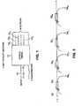
- FIG. 3shows an alternative embodiment of the invention that employs wavelength dependent acoustic null couplers to achieve tunable wavelength filtering.
- a coupleronly cross-couples selected wavelengths from a first to a second optical fiber upon application of an appropriate acoustic vibration to the coupling region. If the appropriate acoustic vibration is not applied, the selected wavelengths continue to propagate along the first optical fiber. Examples of an acoustic null coupler are disclosed in D. O. Culverhouse et al., Opt. Lett. 22, 96, 1997 and U.S. Pat. No. 5,915,050.
- an input fiber 50 receiving the WDM signalis connected to an input port of a first null coupler 52 1 .
- One output port of the first null coupler 52 1is connected to an output fiber 54 1 on which one or more individual wavelength components are to be directed.
- the other output portis connected to an input port of a second null coupler 52 2 .
- the output ports of the second null coupler 52 2are respectively connected to a second output fiber 54 2 and the input port of a third null coupler 52 3 .
- additional null couplersmay be cascaded in this manner to provide additional output ports on which selected wavelength components may be directed.
- one or more wavelength components directed along the input fiber 50can be directed to any selected output port 54 1 , 54 2 , . . . 54 m by applying the appropriate acoustic wave for those components to the null couplers 52 1 , 52 2 , . . . 54 m preceding those connected to the selected output port. For example, if any of the given n wavelength components are to be directed to output port 54 3 , then the acoustic waves should be applied to null coupler 52 3 .
- serial tunable filtering process used in the embodiment of the invention shown in FIG. 4can also achieve the switching functionality of the present invention by using the previously described four-port tunable OADM device technologies.
- FIG. 4shows another alternative embodiment of the invention that employs conventional multiplexers/demultiplexers and conventional 1 xm switches, where n denotes the number of output ports of the switch.
- the multiplexers/demultiplexersmay be employ thin film filters or waveguide gratings, for example.
- an input fiber 60 supporting a WDM signal having n (where n is not necessarily equal to m) wavelength componentsis directed to the input port of demultiplexer 61 .
- the demultiplexer 61has n output ports 63 1 , 63 2 , . . . 63 n , which are respectively coupled to the input ports of the 1 xm switches 65 1 , 65 2 , . . . 65 n .
- the m output ports of the first switch 65 1are respectively connected to the first input ports of the multiplexers 67 1 , 67 2 , . . . 67 m .
- the n output ports of the second switch 65 2are respectively connected to the second input ports of the multiplexers 67 1 , 67 2 , . . . 67 m .
- the remaining switchescontinue to be coupled to the multiplexers in this sequential manner until the output ports of switch 65 n are coupled to the mth input ports of the multiplexers 67 1 , 67 2 , . . . 67 m .
- FIG. 4One problem with the embodiment of the invention shown in FIG. 4 is that it requires a relatively large number of switches and multiplexers/demultiplexers and thus a relatively large number of optical connections.
- the number of optical connectionsscales with the product of the number of wavelength components and the number of output ports.
- the embodiment of the invention shown in FIG. 2only requires 11 optical connections whereas the embodiment shown in FIG. 4 requires 363 optical connections. Since the cost and complexity of the resulting device is directly related to the number of optical connections, the inventive switch shown in FIG. 2 is particularly attractive.
Landscapes
- Engineering & Computer Science (AREA)
- Computer Networks & Wireless Communication (AREA)
- Physics & Mathematics (AREA)
- General Physics & Mathematics (AREA)
- Optics & Photonics (AREA)
- Mechanical Light Control Or Optical Switches (AREA)
- Optical Communication System (AREA)
Abstract
Description
Claims (88)
Priority Applications (17)
| Application Number | Priority Date | Filing Date | Title |
|---|---|---|---|
| US09/571,833US6631222B1 (en) | 2000-05-16 | 2000-05-16 | Reconfigurable optical switch |
| JP2002502486AJP2004515798A (en) | 2000-05-16 | 2001-05-16 | Reconfigurable optical switch |
| EP01975153AEP1297717A2 (en) | 2000-05-16 | 2001-05-16 | A reconfigurable optical switch |
| KR1020027015390AKR20030043792A (en) | 2000-05-16 | 2001-05-16 | A reconfigurable optical switch |
| CN01809624ACN1442026A (en) | 2000-05-16 | 2001-05-16 | Reconfigurable optical switch |
| AU2001266585AAU2001266585A1 (en) | 2000-05-16 | 2001-05-16 | A reconfigurable optical switch |
| CA002409264ACA2409264A1 (en) | 2000-05-16 | 2001-05-16 | A reconfigurable optical switch |
| KR1020027015395AKR20040020785A (en) | 2000-05-16 | 2001-05-16 | A reconfigurable optical switch |
| CN01813944ACN1446438A (en) | 2000-05-16 | 2001-05-16 | Reconfigurable optical switch |
| CA002409216ACA2409216A1 (en) | 2000-05-16 | 2001-05-16 | A reconfigurable optical switch |
| AU2001294506AAU2001294506A1 (en) | 2000-05-16 | 2001-05-16 | A reconfigurable optical switch |
| PCT/US2001/015797WO2001094994A2 (en) | 2000-05-16 | 2001-05-16 | A reconfigurable optical switch |
| EP01944147AEP1283000A2 (en) | 2000-05-16 | 2001-05-16 | A reconfigurable optical switch |
| JP2001585436AJP2004501395A (en) | 2000-05-16 | 2001-05-16 | Reconfigurable optical switch |
| PCT/US2001/015798WO2001089128A2 (en) | 2000-05-16 | 2001-05-16 | A reconfigurable optical switch |
| US10/870,326US7574078B2 (en) | 2000-05-16 | 2004-06-17 | Reconfigurable optical switch |
| US12/539,482US20090297097A1 (en) | 2000-05-16 | 2009-08-11 | Reconfigurable optical switch |
Applications Claiming Priority (1)
| Application Number | Priority Date | Filing Date | Title |
|---|---|---|---|
| US09/571,833US6631222B1 (en) | 2000-05-16 | 2000-05-16 | Reconfigurable optical switch |
Related Child Applications (1)
| Application Number | Title | Priority Date | Filing Date |
|---|---|---|---|
| US69181200AContinuation-In-Part | 2000-05-16 | 2000-10-19 |
Publications (1)
| Publication Number | Publication Date |
|---|---|
| US6631222B1true US6631222B1 (en) | 2003-10-07 |
Family
ID=24285260
Family Applications (1)
| Application Number | Title | Priority Date | Filing Date |
|---|---|---|---|
| US09/571,833Expired - Fee RelatedUS6631222B1 (en) | 2000-05-16 | 2000-05-16 | Reconfigurable optical switch |
Country Status (8)
| Country | Link |
|---|---|
| US (1) | US6631222B1 (en) |
| EP (1) | EP1297717A2 (en) |
| JP (1) | JP2004515798A (en) |
| KR (1) | KR20040020785A (en) |
| CN (1) | CN1442026A (en) |
| AU (1) | AU2001294506A1 (en) |
| CA (1) | CA2409264A1 (en) |
| WO (1) | WO2001094994A2 (en) |
Cited By (31)
| Publication number | Priority date | Publication date | Assignee | Title |
|---|---|---|---|---|
| US20020048423A1 (en)* | 2000-08-07 | 2002-04-25 | Frick Roger L. | Optical switch with moveable holographic optical element |
| US20020145775A1 (en)* | 2001-04-06 | 2002-10-10 | Quantum Bridge Communications, Inc. | TDM/WDMA passive optical network |
| US20020159679A1 (en)* | 2001-03-16 | 2002-10-31 | Strasser Thomas Andrew | Method and apparatus for providing gain equalization to an optical signal in an optical communication system |
| US20030090762A1 (en)* | 2001-09-28 | 2003-05-15 | Mcguire James P. | Littrow grating based oadm |
| US20030206685A1 (en)* | 2001-10-24 | 2003-11-06 | Cheng-Chung Huang | Optical configuration for optical fiber switch |
| US20030215179A1 (en)* | 2001-03-30 | 2003-11-20 | Mcguire James P. | Programmable optical add/drop multiplexer |
| US20030223684A1 (en)* | 2002-05-31 | 2003-12-04 | Jorg-Reinhardt Kropp | Apparatus for demultiplexing optical signals at a large number of wavelengths |
| US20030223681A1 (en)* | 2002-03-01 | 2003-12-04 | Frick Roger L. | Optical switch with 3D waveguides |
| US20040076366A1 (en)* | 2002-10-18 | 2004-04-22 | Chang-Han Yun | Fiber-attached optical devices with in-plane micromachined mirrors |
| US6853762B1 (en)* | 2002-05-24 | 2005-02-08 | Cypress Semiconductor Corporation | Optical switch cascading system and method with variable incidence angle correction |
| US6870982B1 (en) | 2002-08-23 | 2005-03-22 | Cypress Semiconductor Corporation | Cascading optical switch three dimensional switch fabric system and method |
| US6882769B1 (en)* | 2001-10-24 | 2005-04-19 | Intel Corporation | Control system for an optical fiber switch |
| US20050163411A1 (en)* | 2000-11-15 | 2005-07-28 | Fuji Photo Film Co., Ltd. | Optical modulator, exposure head and image recording apparatus |
| US20050169576A1 (en)* | 2002-09-30 | 2005-08-04 | Capewell Dale L. | System and method for packaging a monitor photodiode with a laser in an optical subassembly |
| US6983087B1 (en)* | 2002-05-24 | 2006-01-03 | Cypress Semiconductor Corporation | Cascading optical switch multi-plane system and method |
| US20060034610A1 (en)* | 2004-08-16 | 2006-02-16 | Fujitsu Limited | Optical add/drop multiplexer |
| US7013058B1 (en) | 2002-05-24 | 2006-03-14 | Cypress Semiconductor Corporation | Optical switch cascading system and method with fixed incidence angle correction |
| GB2419484A (en)* | 2004-10-22 | 2006-04-26 | Zhou Rong | Optical N x M switch |
| US20070009261A1 (en)* | 2001-11-15 | 2007-01-11 | Nielsen Torben N | Optical WDM transmission system having a distributed arrangement of regenerators |
| US20070047113A1 (en)* | 2001-06-02 | 2007-03-01 | Capella Photonics, Inc. | High fill-factor bulk silicon mirrors with reduced effect of mirror edge diffraction |
| US20070070919A1 (en)* | 2005-09-28 | 2007-03-29 | Fujitsu Limited | Device and method for network configuration and computer product |
| US20070104418A1 (en)* | 2002-06-12 | 2007-05-10 | Mcguire James P Jr | Wavelength selective optical switch |
| US7257288B1 (en) | 2004-04-23 | 2007-08-14 | Nistica, Inc. | Tunable optical routing systems |
| US20080131119A1 (en)* | 2006-12-05 | 2008-06-05 | Fujitsu Limited | Lens adjusting method, lens adjusting device, and optical switch |
| US7408639B1 (en) | 2004-04-23 | 2008-08-05 | Nistica, Inc. | Tunable optical routing systems |
| US20090297097A1 (en)* | 2000-05-16 | 2009-12-03 | Meriton Networks Us Inc. | Reconfigurable optical switch |
| US20100021162A1 (en)* | 2001-03-16 | 2010-01-28 | Meriton Networks Us Inc. | Wavelength division multiplexed optical communication system having a reconfigurable optical switch and a tunable backup laser transmitter |
| USRE42368E1 (en) | 2001-03-19 | 2011-05-17 | Capella Photonics, Inc. | Reconfigurable optical add-drop multiplexers with servo control and dynamic spectral power management capabilities |
| USRE42521E1 (en) | 2001-03-19 | 2011-07-05 | Capella Photonics, Inc. | Reconfigurable optical add-drop multiplexers employing polarization diversity |
| US20180226282A1 (en)* | 2017-02-03 | 2018-08-09 | Applied Materials, Inc. | Non-contact substrate temperature measurement technique based on spectral inteferometry |
| US10393580B2 (en)* | 2017-07-26 | 2019-08-27 | Samsung Electronics Co., Ltd. | Spectrometer including light filter |
Families Citing this family (3)
| Publication number | Priority date | Publication date | Assignee | Title |
|---|---|---|---|---|
| GB0203037D0 (en)* | 2002-02-08 | 2002-03-27 | Marconi Comm Ltd | Telecommunications networks |
| KR100734851B1 (en)* | 2005-12-01 | 2007-07-03 | 한국전자통신연구원 | Multi-wavelength selector |
| CN113534353A (en)* | 2021-06-23 | 2021-10-22 | 桂林光隆集成科技有限公司 | Wavelength selective switch and debugging method |
Citations (22)
| Publication number | Priority date | Publication date | Assignee | Title |
|---|---|---|---|---|
| US4244045A (en) | 1978-01-31 | 1981-01-06 | Nippon Telegraph And Telephone Public Corporation | Optical multiplexer and demultiplexer |
| JPS6088907A (en)* | 1983-10-20 | 1985-05-18 | Fujitsu Ltd | Optical multiplexer/demultiplexer |
| US4626066A (en) | 1983-12-30 | 1986-12-02 | At&T Bell Laboratories | Optical coupling device utilizing a mirror and cantilevered arm |
| US5479082A (en) | 1993-08-10 | 1995-12-26 | Cselt-Centro Studi E Laboratorti Telecommunicazioni S.P.A. | Device for extraction and re-insertion of an optical carrier in optical communications networks |
| US5504827A (en) | 1993-08-06 | 1996-04-02 | Siemens Aktiengesellschaft | Programmable optical filter and optical circuit arrangement |
| US5583683A (en) | 1995-06-15 | 1996-12-10 | Optical Corporation Of America | Optical multiplexing device |
| US5612805A (en) | 1994-06-07 | 1997-03-18 | Alcatel Cit | Add-drop optical spectrum-division multiplexer |
| US5621829A (en) | 1996-04-02 | 1997-04-15 | Lucent Technologies Inc. | Fiber optic switching device and method using free space scanning |
| US5808763A (en)* | 1995-10-31 | 1998-09-15 | Jds Fitel Inc. | Optical demultiplexor |
| US5835517A (en) | 1996-10-04 | 1998-11-10 | W. L. Gore & Associates, Inc. | WDM multiplexer-demultiplexer using Fabry-Perot filter array |
| US5841917A (en) | 1997-01-31 | 1998-11-24 | Hewlett-Packard Company | Optical cross-connect switch using a pin grid actuator |
| US5915050A (en) | 1994-02-18 | 1999-06-22 | University Of Southampton | Optical device |
| US5920411A (en)* | 1997-02-14 | 1999-07-06 | Duck; Gary S. | Optical multiplexing/demultiplexing device |
| US5959749A (en) | 1998-05-20 | 1999-09-28 | Nortel Networks Corporation | Optical add/drop multiplexer/demultiplexer |
| US5960133A (en) | 1998-01-27 | 1999-09-28 | Tellium, Inc. | Wavelength-selective optical add/drop using tilting micro-mirrors |
| US5974207A (en) | 1997-12-23 | 1999-10-26 | Lucent Technologies, Inc. | Article comprising a wavelength-selective add-drop multiplexer |
| US6005993A (en)* | 1997-11-14 | 1999-12-21 | Macdonald; Robert I. | Deflection optical matrix switch |
| US6008920A (en)* | 1998-03-11 | 1999-12-28 | Optical Coating Laboratory, Inc. | Multiple channel multiplexer/demultiplexer devices |
| US6028689A (en) | 1997-01-24 | 2000-02-22 | The United States Of America As Represented By The Secretary Of The Air Force | Multi-motion micromirror |
| US6075632A (en)* | 1997-11-26 | 2000-06-13 | Hewlett-Packard Company | Optical noise monitor |
| US6289148B1 (en)* | 1998-12-14 | 2001-09-11 | At&T Corporation | Free-space micro-mirror wavelength add/drop multiplexers with full connectivity for two-fiber ring networks |
| US6327398B1 (en) | 1997-02-13 | 2001-12-04 | The Regents Of The University Of California | Multi-wavelength cross-connect optical switch |
- 2000
- 2000-05-16USUS09/571,833patent/US6631222B1/ennot_activeExpired - Fee Related
- 2001
- 2001-05-16CNCN01809624Apatent/CN1442026A/enactivePending
- 2001-05-16AUAU2001294506Apatent/AU2001294506A1/ennot_activeAbandoned
- 2001-05-16EPEP01975153Apatent/EP1297717A2/ennot_activeWithdrawn
- 2001-05-16JPJP2002502486Apatent/JP2004515798A/ennot_activeWithdrawn
- 2001-05-16CACA002409264Apatent/CA2409264A1/ennot_activeAbandoned
- 2001-05-16WOPCT/US2001/015797patent/WO2001094994A2/enactiveApplication Filing
- 2001-05-16KRKR1020027015395Apatent/KR20040020785A/ennot_activeCeased
Patent Citations (22)
| Publication number | Priority date | Publication date | Assignee | Title |
|---|---|---|---|---|
| US4244045A (en) | 1978-01-31 | 1981-01-06 | Nippon Telegraph And Telephone Public Corporation | Optical multiplexer and demultiplexer |
| JPS6088907A (en)* | 1983-10-20 | 1985-05-18 | Fujitsu Ltd | Optical multiplexer/demultiplexer |
| US4626066A (en) | 1983-12-30 | 1986-12-02 | At&T Bell Laboratories | Optical coupling device utilizing a mirror and cantilevered arm |
| US5504827A (en) | 1993-08-06 | 1996-04-02 | Siemens Aktiengesellschaft | Programmable optical filter and optical circuit arrangement |
| US5479082A (en) | 1993-08-10 | 1995-12-26 | Cselt-Centro Studi E Laboratorti Telecommunicazioni S.P.A. | Device for extraction and re-insertion of an optical carrier in optical communications networks |
| US5915050A (en) | 1994-02-18 | 1999-06-22 | University Of Southampton | Optical device |
| US5612805A (en) | 1994-06-07 | 1997-03-18 | Alcatel Cit | Add-drop optical spectrum-division multiplexer |
| US5583683A (en) | 1995-06-15 | 1996-12-10 | Optical Corporation Of America | Optical multiplexing device |
| US5808763A (en)* | 1995-10-31 | 1998-09-15 | Jds Fitel Inc. | Optical demultiplexor |
| US5621829A (en) | 1996-04-02 | 1997-04-15 | Lucent Technologies Inc. | Fiber optic switching device and method using free space scanning |
| US5835517A (en) | 1996-10-04 | 1998-11-10 | W. L. Gore & Associates, Inc. | WDM multiplexer-demultiplexer using Fabry-Perot filter array |
| US6028689A (en) | 1997-01-24 | 2000-02-22 | The United States Of America As Represented By The Secretary Of The Air Force | Multi-motion micromirror |
| US5841917A (en) | 1997-01-31 | 1998-11-24 | Hewlett-Packard Company | Optical cross-connect switch using a pin grid actuator |
| US6327398B1 (en) | 1997-02-13 | 2001-12-04 | The Regents Of The University Of California | Multi-wavelength cross-connect optical switch |
| US5920411A (en)* | 1997-02-14 | 1999-07-06 | Duck; Gary S. | Optical multiplexing/demultiplexing device |
| US6005993A (en)* | 1997-11-14 | 1999-12-21 | Macdonald; Robert I. | Deflection optical matrix switch |
| US6075632A (en)* | 1997-11-26 | 2000-06-13 | Hewlett-Packard Company | Optical noise monitor |
| US5974207A (en) | 1997-12-23 | 1999-10-26 | Lucent Technologies, Inc. | Article comprising a wavelength-selective add-drop multiplexer |
| US5960133A (en) | 1998-01-27 | 1999-09-28 | Tellium, Inc. | Wavelength-selective optical add/drop using tilting micro-mirrors |
| US6008920A (en)* | 1998-03-11 | 1999-12-28 | Optical Coating Laboratory, Inc. | Multiple channel multiplexer/demultiplexer devices |
| US5959749A (en) | 1998-05-20 | 1999-09-28 | Nortel Networks Corporation | Optical add/drop multiplexer/demultiplexer |
| US6289148B1 (en)* | 1998-12-14 | 2001-09-11 | At&T Corporation | Free-space micro-mirror wavelength add/drop multiplexers with full connectivity for two-fiber ring networks |
Non-Patent Citations (6)
| Title |
|---|
| C.R. Doerr, Proposed WDM Cross Connect Using A Planar Arrangement of Waveguide Grating Routers and Phase Shifters, Photonics Technology Letters, vol. 10, No. 4, Apr. 1998. |
| C.R. Giles, et al., "Low-Loss ADD/DROP Multiplexers for WDM Lightwave Networks," Tenth International Conference on Integrated Optics and Optical Fibre Communication, IOOC, vol. 3, Jun. 29, 1995. |
| D.O.Culverhouse et al., Low-loss all-fiber acousto-optic tunable filter, Optical Society of America, vol. 22, No. 2, Jan. 15, 1997, pp. 96-98. |
| E. Murphy, Optical Fiber Telecommunications IIIB, Chapter 10, edited by T. Koch and I. Kaminow, Academic Press. |
| JDS Uniphase Corporation, Add-Drop Modules, Product Bulletin 2000, Ontario, Canada. |
| Roberto Sabella et al., "Impact of Transmission Performance on Path Routing in All-Optical Transport Networks,", Journal of Lightware Technology, vol. 16, No. 11 (Nov. 1998),pp. 1965-1971. |
Cited By (60)
| Publication number | Priority date | Publication date | Assignee | Title |
|---|---|---|---|---|
| US20090297097A1 (en)* | 2000-05-16 | 2009-12-03 | Meriton Networks Us Inc. | Reconfigurable optical switch |
| US7003187B2 (en) | 2000-08-07 | 2006-02-21 | Rosemount Inc. | Optical switch with moveable holographic optical element |
| US20020048423A1 (en)* | 2000-08-07 | 2002-04-25 | Frick Roger L. | Optical switch with moveable holographic optical element |
| US20050163411A1 (en)* | 2000-11-15 | 2005-07-28 | Fuji Photo Film Co., Ltd. | Optical modulator, exposure head and image recording apparatus |
| US20100098406A1 (en)* | 2001-03-16 | 2010-04-22 | Meriton Networks Us Inc. | Method and apparatus for interconnecting a plurality of optical transducers with a wavelength division multiplexed optical switch |
| US20090142060A1 (en)* | 2001-03-16 | 2009-06-04 | Meriton Networks Us Inc. | Method and apparatus for transferring wdm signals between different wavelength division multiplexed optical communications systems in an optically transparent manner |
| US9258628B2 (en) | 2001-03-16 | 2016-02-09 | Linkedin Corporation | Method and apparatus for transferring WDM signals between different wavelength division multiplexed optical communications systems in an optically transparent manner |
| US20100021162A1 (en)* | 2001-03-16 | 2010-01-28 | Meriton Networks Us Inc. | Wavelength division multiplexed optical communication system having a reconfigurable optical switch and a tunable backup laser transmitter |
| US20020159679A1 (en)* | 2001-03-16 | 2002-10-31 | Strasser Thomas Andrew | Method and apparatus for providing gain equalization to an optical signal in an optical communication system |
| US7676157B2 (en)* | 2001-03-16 | 2010-03-09 | Meriton Networks Us Inc. | Method and apparatus for providing gain equalization to an optical signal in an optical communication system |
| USRE42678E1 (en) | 2001-03-19 | 2011-09-06 | Capella Photonics, Inc. | Reconfigurable optical add-drop multiplexers with servo control and dynamic spectral power management capabilities |
| USRE47906E1 (en) | 2001-03-19 | 2020-03-17 | Capella Photonics, Inc. | Reconfigurable optical add-drop multiplexers with servo control and dynamic spectral power management capabilities |
| USRE42521E1 (en) | 2001-03-19 | 2011-07-05 | Capella Photonics, Inc. | Reconfigurable optical add-drop multiplexers employing polarization diversity |
| USRE47905E1 (en) | 2001-03-19 | 2020-03-17 | Capella Photonics, Inc. | Reconfigurable optical add-drop multiplexers with servo control and dynamic spectral power management capabilities |
| USRE42368E1 (en) | 2001-03-19 | 2011-05-17 | Capella Photonics, Inc. | Reconfigurable optical add-drop multiplexers with servo control and dynamic spectral power management capabilities |
| US20030215179A1 (en)* | 2001-03-30 | 2003-11-20 | Mcguire James P. | Programmable optical add/drop multiplexer |
| US7177493B2 (en)* | 2001-03-30 | 2007-02-13 | Optical Research Associates | Programmable optical add/drop multiplexer |
| US20020145775A1 (en)* | 2001-04-06 | 2002-10-10 | Quantum Bridge Communications, Inc. | TDM/WDMA passive optical network |
| US20070047113A1 (en)* | 2001-06-02 | 2007-03-01 | Capella Photonics, Inc. | High fill-factor bulk silicon mirrors with reduced effect of mirror edge diffraction |
| US20030090762A1 (en)* | 2001-09-28 | 2003-05-15 | Mcguire James P. | Littrow grating based oadm |
| US7203421B2 (en) | 2001-09-28 | 2007-04-10 | Optical Research Associates | Littrow grating based OADM |
| US6882769B1 (en)* | 2001-10-24 | 2005-04-19 | Intel Corporation | Control system for an optical fiber switch |
| US6925221B2 (en)* | 2001-10-24 | 2005-08-02 | Intel Corporation | Control system for an optical fiber switch |
| US20030206685A1 (en)* | 2001-10-24 | 2003-11-06 | Cheng-Chung Huang | Optical configuration for optical fiber switch |
| US6922500B2 (en) | 2001-10-24 | 2005-07-26 | Intel Corporation | Optical configuration for optical fiber switch |
| US7831153B2 (en) | 2001-11-15 | 2010-11-09 | Xtera Communications, Inc. | Optical WDM transmission system having a distributed arrangement of regenerators |
| US20070009261A1 (en)* | 2001-11-15 | 2007-01-11 | Nielsen Torben N | Optical WDM transmission system having a distributed arrangement of regenerators |
| US6987901B2 (en)* | 2002-03-01 | 2006-01-17 | Rosemount, Inc. | Optical switch with 3D waveguides |
| US20030223681A1 (en)* | 2002-03-01 | 2003-12-04 | Frick Roger L. | Optical switch with 3D waveguides |
| US7013058B1 (en) | 2002-05-24 | 2006-03-14 | Cypress Semiconductor Corporation | Optical switch cascading system and method with fixed incidence angle correction |
| US6983087B1 (en)* | 2002-05-24 | 2006-01-03 | Cypress Semiconductor Corporation | Cascading optical switch multi-plane system and method |
| US6853762B1 (en)* | 2002-05-24 | 2005-02-08 | Cypress Semiconductor Corporation | Optical switch cascading system and method with variable incidence angle correction |
| US6928210B2 (en)* | 2002-05-31 | 2005-08-09 | Infineon Technologies Ag | Apparatus for demultiplexing optical signals at a large number of wavelengths |
| US20030223684A1 (en)* | 2002-05-31 | 2003-12-04 | Jorg-Reinhardt Kropp | Apparatus for demultiplexing optical signals at a large number of wavelengths |
| US20080205821A1 (en)* | 2002-06-12 | 2008-08-28 | Optical Research Associates | Wavelength selective optical switch |
| US7519247B2 (en) | 2002-06-12 | 2009-04-14 | Optical Research Associates | Wavelength selective optical switch |
| US20070104418A1 (en)* | 2002-06-12 | 2007-05-10 | Mcguire James P Jr | Wavelength selective optical switch |
| US7330615B2 (en) | 2002-06-12 | 2008-02-12 | Optical Research Associates | Wavelength selective optical switch |
| US6870982B1 (en) | 2002-08-23 | 2005-03-22 | Cypress Semiconductor Corporation | Cascading optical switch three dimensional switch fabric system and method |
| US7024074B2 (en) | 2002-09-30 | 2006-04-04 | Intel Corporation | System and method for packaging a monitor photodiode with a laser in an optical subassembly |
| US20050169576A1 (en)* | 2002-09-30 | 2005-08-04 | Capewell Dale L. | System and method for packaging a monitor photodiode with a laser in an optical subassembly |
| US6963683B2 (en)* | 2002-09-30 | 2005-11-08 | Intel Corporation | System and method for a packaging a monitor photodiode with a laser in an optical subassembly |
| US20040076366A1 (en)* | 2002-10-18 | 2004-04-22 | Chang-Han Yun | Fiber-attached optical devices with in-plane micromachined mirrors |
| US6931170B2 (en)* | 2002-10-18 | 2005-08-16 | Analog Devices, Inc. | Fiber-attached optical devices with in-plane micromachined mirrors |
| US7965911B1 (en) | 2004-04-23 | 2011-06-21 | Nistica, Inc. | Method of operating a tunable optical device |
| US7639906B1 (en) | 2004-04-23 | 2009-12-29 | Nistica, Inc. | Tunable optical communication system |
| US7408639B1 (en) | 2004-04-23 | 2008-08-05 | Nistica, Inc. | Tunable optical routing systems |
| US7257288B1 (en) | 2004-04-23 | 2007-08-14 | Nistica, Inc. | Tunable optical routing systems |
| US7853148B2 (en) | 2004-08-16 | 2010-12-14 | Fujitsu Limited | Optical add/drop multiplexer |
| US20110038636A1 (en)* | 2004-08-16 | 2011-02-17 | Fujitsu Limited | Optical Add/Drop Multiplexer |
| US20090148166A1 (en)* | 2004-08-16 | 2009-06-11 | Fujitsu Limited | Optical Add/Drop Multiplexer |
| US8131152B2 (en) | 2004-08-16 | 2012-03-06 | Fujitsu Limited | Optical add/drop multiplexer |
| US20060034610A1 (en)* | 2004-08-16 | 2006-02-16 | Fujitsu Limited | Optical add/drop multiplexer |
| US7792428B2 (en) | 2004-08-16 | 2010-09-07 | Fujitsu Limited | Optical add/drop multiplexer |
| GB2419484A (en)* | 2004-10-22 | 2006-04-26 | Zhou Rong | Optical N x M switch |
| US20070070919A1 (en)* | 2005-09-28 | 2007-03-29 | Fujitsu Limited | Device and method for network configuration and computer product |
| US7570848B2 (en) | 2006-12-05 | 2009-08-04 | Fujitsu Limited | Lens adjusting method, lens adjusting device, and optical switch |
| US20080131119A1 (en)* | 2006-12-05 | 2008-06-05 | Fujitsu Limited | Lens adjusting method, lens adjusting device, and optical switch |
| US20180226282A1 (en)* | 2017-02-03 | 2018-08-09 | Applied Materials, Inc. | Non-contact substrate temperature measurement technique based on spectral inteferometry |
| US10393580B2 (en)* | 2017-07-26 | 2019-08-27 | Samsung Electronics Co., Ltd. | Spectrometer including light filter |
Also Published As
| Publication number | Publication date |
|---|---|
| JP2004515798A (en) | 2004-05-27 |
| KR20040020785A (en) | 2004-03-09 |
| EP1297717A2 (en) | 2003-04-02 |
| CN1442026A (en) | 2003-09-10 |
| WO2001094994A3 (en) | 2003-01-16 |
| CA2409264A1 (en) | 2001-12-13 |
| AU2001294506A1 (en) | 2001-12-17 |
| WO2001094994A2 (en) | 2001-12-13 |
Similar Documents
| Publication | Publication Date | Title |
|---|---|---|
| US6631222B1 (en) | Reconfigurable optical switch | |
| US20090297097A1 (en) | Reconfigurable optical switch | |
| US6614953B2 (en) | Modular all-optical cross-connect | |
| CA2392704C (en) | System and method of optical switching | |
| US20070041683A1 (en) | Tunable Optical Filter | |
| KR20010024132A (en) | Wavelength-selective optical switching apparatus, optical communications apparatus using the same, and method for use in the optical communications apparatus | |
| US7529441B2 (en) | Wavelength routing optical switch | |
| US6956987B2 (en) | Planar lightwave wavelength blocker devices using micromachines | |
| EP1089479B1 (en) | Wavelength division add/drop multiplexer | |
| US6587608B2 (en) | Reconfigurable, all optical add/drop nodes using non-interrupting switching apparatus and methods | |
| US7062174B2 (en) | Wavelength division multiplexing add-drop multiplexer using an optical tapped delay line | |
| WO2002095467A2 (en) | Reconfigurable optical add/drop module | |
| US6950571B1 (en) | Optical switchable component |
Legal Events
| Date | Code | Title | Description |
|---|---|---|---|
| AS | Assignment | Owner name:PHOTURIS, INC., NEW JERSEY Free format text:ASSIGNMENT OF ASSIGNORS INTEREST;ASSIGNORS:WAGENER, JEFFERSON L.;STRASSER, THOMAS ANDREW;REEL/FRAME:014302/0557 Effective date:20000809 | |
| AS | Assignment | Owner name:JURISTA, MR. STEVEN Z., NEW JERSEY Free format text:ASSIGNMENT OF ASSIGNORS INTEREST;ASSIGNOR:PHOTURIS, INC.;REEL/FRAME:014990/0969 Effective date:20040408 Owner name:JURISTA, MR. STEVEN Z.,NEW JERSEY Free format text:ASSIGNMENT OF ASSIGNORS INTEREST;ASSIGNOR:PHOTURIS, INC.;REEL/FRAME:014990/0969 Effective date:20040408 | |
| AS | Assignment | Owner name:MAHI NETWORKS, INC., CALIFORNIA Free format text:ASSIGNMENT OF ASSIGNORS INTEREST;ASSIGNOR:JURISTA, MR. STEVEN Z.;REEL/FRAME:015147/0593 Effective date:20040608 Owner name:MAHI NETWORKS, INC.,CALIFORNIA Free format text:ASSIGNMENT OF ASSIGNORS INTEREST;ASSIGNOR:JURISTA, MR. STEVEN Z.;REEL/FRAME:015147/0593 Effective date:20040608 | |
| AS | Assignment | Owner name:MAHI NETWORKS, INC.,CALIFORNIA Free format text:SALE DUE TO BANKRUPTCY;ASSIGNOR:PHOTURIS, INC.;REEL/FRAME:016996/0483 Effective date:20040506 Owner name:MAHI NETWORKS, INC., CALIFORNIA Free format text:SALE DUE TO BANKRUPTCY;ASSIGNOR:PHOTURIS, INC.;REEL/FRAME:016996/0483 Effective date:20040506 | |
| AS | Assignment | Owner name:MERITON NETWORKS US INC.,DELAWARE Free format text:MERGER;ASSIGNOR:MAHI NETWORKS, INC.;REEL/FRAME:016996/0958 Effective date:20051110 Owner name:MERITON NETWORKS US INC., DELAWARE Free format text:MERGER;ASSIGNOR:MAHI NETWORKS, INC.;REEL/FRAME:016996/0958 Effective date:20051110 | |
| AS | Assignment | Owner name:HORIZON TECHNOLOGY FUNDING COMPANY LLC,CONNECTICUT Free format text:SECURITY AGREEMENT;ASSIGNOR:MERITON NETWORKS INC.;REEL/FRAME:018934/0670 Effective date:20061218 Owner name:HORIZON TECHNOLOGY FUNDING COMPANY LLC, CONNECTICU Free format text:SECURITY AGREEMENT;ASSIGNOR:MERITON NETWORKS INC.;REEL/FRAME:018934/0670 Effective date:20061218 | |
| FPAY | Fee payment | Year of fee payment:4 | |
| CC | Certificate of correction | ||
| REMI | Maintenance fee reminder mailed | ||
| LAPS | Lapse for failure to pay maintenance fees | ||
| STCH | Information on status: patent discontinuation | Free format text:PATENT EXPIRED DUE TO NONPAYMENT OF MAINTENANCE FEES UNDER 37 CFR 1.362 | |
| FP | Lapsed due to failure to pay maintenance fee | Effective date:20111007 | |
| AS | Assignment | Owner name:MERITON NETWORKS, INC., TEXAS Free format text:ASSIGNMENT OF ASSIGNORS INTEREST;ASSIGNOR:MERITON NETWORKS US, INC.;REEL/FRAME:028388/0810 Effective date:20061201 | |
| AS | Assignment | Owner name:XTERA COMMUNICATIONS, INC., TEXAS Free format text:ASSIGNMENT OF ASSIGNORS INTEREST;ASSIGNOR:MERITON NETWORKS, INC.;REEL/FRAME:028541/0891 Effective date:20120501 |