US6631132B1 - Urgent packet transmission - Google Patents
Urgent packet transmissionDownload PDFInfo
- Publication number
- US6631132B1 US6631132B1US09/411,287US41128799AUS6631132B1US 6631132 B1US6631132 B1US 6631132B1US 41128799 AUS41128799 AUS 41128799AUS 6631132 B1US6631132 B1US 6631132B1
- Authority
- US
- United States
- Prior art keywords
- packet
- bits
- transmitting
- receiver
- packets
- Prior art date
- Legal status (The legal status is an assumption and is not a legal conclusion. Google has not performed a legal analysis and makes no representation as to the accuracy of the status listed.)
- Expired - Lifetime
Links
- 230000005540biological transmissionEffects0.000titleclaimsdescription37
- 238000000034methodMethods0.000claimsabstractdescription37
- 239000000872bufferSubstances0.000claimsdescription29
- 238000004891communicationMethods0.000description10
- 238000006073displacement reactionMethods0.000description5
- 239000012634fragmentSubstances0.000description2
- 238000012790confirmationMethods0.000description1
- 230000007423decreaseEffects0.000description1
- 230000000694effectsEffects0.000description1
- 238000013467fragmentationMethods0.000description1
- 238000006062fragmentation reactionMethods0.000description1
- 230000036039immunityEffects0.000description1
- 238000005259measurementMethods0.000description1
Images


Classifications
- H—ELECTRICITY
- H04—ELECTRIC COMMUNICATION TECHNIQUE
- H04L—TRANSMISSION OF DIGITAL INFORMATION, e.g. TELEGRAPHIC COMMUNICATION
- H04L47/00—Traffic control in data switching networks
- H04L47/10—Flow control; Congestion control
- H—ELECTRICITY
- H04—ELECTRIC COMMUNICATION TECHNIQUE
- H04L—TRANSMISSION OF DIGITAL INFORMATION, e.g. TELEGRAPHIC COMMUNICATION
- H04L47/00—Traffic control in data switching networks
- H04L47/10—Flow control; Congestion control
- H04L47/24—Traffic characterised by specific attributes, e.g. priority or QoS
- H04L47/245—Traffic characterised by specific attributes, e.g. priority or QoS using preemption
Definitions
- the present inventionrelates to communication networks and particularly to packet based networks which accommodate packets of various priorities.
- Messages transmitted from a source to a destination over a packet based networkare broken up by the source into packets which are sent to the destination independently of each other.
- a headeris annexed to each packet.
- the headeridentifies the packet providing, among other information, the source and destination of the packet, the length of the packet, and the message to which the packet belongs.
- the length of the packet which appears in the headeris used by the destination to determine which of the bits it receives belongs to the packet. Therefore, changing the length of the packet after the header was transmitted is not considered feasible.
- time critical urgent datasuch as real time packets, and non-urgent data
- precedencemust be given to the time critical data.
- the precedenceis given by tagging the time critical packets as urgent and transmitting the urgent packets before other packets from a buffer of the source.
- a sourcebegins transmitting a long packet of about 1500 bytes and after only a few bits are sent an urgent packet is received in the buffer of the source, the urgent packet will have to wait for the entire long packet to be sent. On links with a speed of 9600 bits/second, this can require more than a second.
- One method of reducing the delay incurred on urgent packetsis to reduce the maximal size of all the packets transmitted along the link.
- the maximal amount of time that an urgent packet must waitis less than when full size packets are transmitted on the link.
- the size of large packetsmay be reduced by fragmenting the long packet into a plurality of fragment packets with separate headers. This, however, decreases the ratio between the data amount and the length of the header of the packets and/or fragments.
- An aspect of some preferred embodiments of the inventionrelates to a communication system which supports interrupts during transmission of a packet.
- the transmittersends an interrupt signal to the receiver, indicating that an urgent packet is being transmitted before the completion of the transmission of the current packet.
- the transmittercontinues to transmit the packet which was interrupted, from the point at which it was interrupted.
- the interrupt signalsare sent as interrupt indication bits within the interrupted packet.
- the interrupt indication bitsmay be placed within the packets only at predetermined stop points.
- the locations of the stop pointsare fixed for all the transmitted packets.
- the stop pointsmay be located after every 64 (or any other number) of transmitted bits.
- the locations of the stop pointsare a function of information in a header of the current packet and/or of external information, such as data on the connectivity of a network including the transmitter and receiver and the time of day.
- one or more bitsare inserted at each of the stop points regardless of whether an interrupt is being declared.
- the one or more inserted bitspreferably have two possible values, either “no interrupt” or “interrupt”. Normally, the one or more inserted bits have a no interrupt value.
- the transmittersets the value of the one or more inserted bits to interrupt and immediately begins transmitting the urgent packet.
- the transmitterupon receiving an urgent packet, the transmitter immediately begins to transmit the urgent packet instead of the current packet, and sets the indication bits at the next stop point, accordingly.
- a second packet which interrupted a first packetmay also be interrupted by a third packet.
- the packetsare assigned levels of urgency and each packet may interrupt those packets which are less urgent than the interrupting packet.
- An aspect of some preferred embodiments of the inventionrelates to assigning stop points and inserting bits at the stop points to indicate no interrupts, only to some of the packets transmitted by a specific transmitter.
- packets of a high urgency levelare sent without inserted bits, and therefore these packets are never interrupted.
- packets shorter than a predetermined lengthare sent without inserted bits.
- a short set of bitsis added to each transmitted packet to indicate whether the packet includes inserted bits.
- interrupt indication bitsare inserted only in packets sent to specific destinations, for example, destinations which comprise apparatus which supports interrupt indication bits.
- a method of transmitting packets from a transmitter to a receiverincluding providing a first packet including a header, transmitting a leading part of the first packet on a link from the transmitter to the receiver, the leading part not including a header separate from the header of the entire packet, and transmitting a second packet on the link after the leading part of the first packet was transmitted and before a remaining part of the first packet was transmitted.
- transmitting the second packetincludes transmitting a packet which is more urgent than the first packet.
- the second packetincludes a real time audio packet.
- the methodincludes notifying the receiver, after transmitting the leading part of the first packet, that data transmitted on the channel from a specific point on belongs to the second packet.
- notifying the receiverincludes transmitting a predetermined sequence of bits on the channel after the leading part of the first packet.
- transmitting a predetermined sequence of bitsincludes transmitting the sequence at one or more predetermined stop points along the first packet.
- the methodincludes transmitting a predetermined sequence of bits, different from the sequence used to notify that the data from a specific point on belongs to the second packet, at those predetermined stop points not used for the notifying.
- notifying the receiver that the bits transmitted from a specific point on belong to the second packetincludes notifying the receiver before transmitting any part of the second packet.
- notifying the receiver that the bits transmitted from a specific point on belong to the second packetincludes notifying the receiver that the bits transmitted immediately after the notification belong to the second packet.
- notifying the receiver that the bits transmitted from a specific point on belong to the second packetincludes notifying the receiver after transmitting at least part of the second packet.
- the methodincludes transmitting a remaining part of the first packet, not previously transmitted, after transmitting the second packet.
- the leading part of the first packetis not retransmitted after transmitting the second packet.
- the second packetis ready for transmission only after the transmitting of the leading part of the first packet.
- transmitting the leading part of the first packetincludes transmitting a field which indicates the length of the entire first packet.
- transmitting the second packetincludes receiving the second packet after the transmitting of the leading part of the first packet, determining whether the second packet should be transmitted prior to the transmission of a remainder of the first packet, and transmitting the second packet responsive to the determination.
- a plurality of first packetsare transmitted on the link and transmitting the second packet before a remaining part of the first packet was transmitted is performed for less than all of the first packets.
- a method of transmitting packets from a transmitter to a receiverincluding beginning to transmit a first packet, receiving a second packet after transmitting one or more bits of the first packet, determining whether the second packet should be transmitted prior to the transmission of a remainder of the first packet, and transmitting the second packet responsive to the determination before transmitting a remaining part of the first packet.
- a method of transmitting packets from a transmitter to a receiverincluding transmitting a first packet from the transmitter to the receiver, and transmitting at predetermined stop points within the first packet a set of bits which indicate that no interruption is being declared in the transmission of the first packet.
- the set of indicating bitsindicates that the following bits until a next stop point belong to the first packet.
- the set of indicating bitsindicates that the previous bits from a previous stop point belong to the first packet.
- the predetermined stop pointsare located at predetermined fixed intervals of bits within the first packet.
- the predetermined stop pointsare located at adjustable locations within the first packet.
- indication of the locations of the predetermined stop pointsis contained in at least one field of a header of the first packet.
- a transmitterincluding a buffer operative to receive regular packets and urgent packets, a physical layer unit which transmits packets from the buffer, and a controller adapted to interrupt the transmission of a packet of which at least one bit was already transmitted and to initiate the transmission of an urgent packet before a remaining part of the interrupted packet was transmitted responsive to reception of the urgent packet in the buffer.
- the bufferincludes a regular buffer for regular packets and an urgent buffer for urgent packets.
- a transmitterincluding a buffer which receives packets which include respective headers, and a physical layer unit which transmits packets from the buffer, at least one first packet is transmitted after transmitting a leading part of a second packet and before transmitting a remaining part of the second packet, the leading part of the second packet not including a header separate from the header of the entire second packet.
- a transmitterincluding a buffer which receives packets for transmission, a physical layer unit which transmits packets from the buffer, and a processor which inserts at predetermined stop points within the transmitted packets a set of bits which indicates whether an interruption is being declared in the transmission of the packet.
- a receiverincluding a physical layer unit which receives bits over a link, and a processor which groups the bits into packets, at least one first packet is grouped from bits received after receiving a leading part of a second packet and before receiving a remaining part of the second packet, the leading part of the second packet not including a header separate from the header of the entire second packet.
- a receiverincluding a physical layer unit which receives a stream of bits, and a processor which examines at predetermined stop points within the stream a set of bits which indicates whether the stream includes bits from a second packet before all the bits from a first packet were included in the stream.
- the processorremoves the set of bits from the stream.
- the processoris adapted to divide the stream into packets responsive to the examination.
- a communication systemincluding a communication link, a transmitter operative to transmit a stream of bits on the communication link, which stream includes one or more sets of indication bits which indicate whether bits from a first packet have been included in the stream between bits from a second packet, and a receiver operative to identify the indication bits and parse the stream into packets responsive to the indication bits.
- a communication systemincluding a communication link, a receiver which receives packets over the communication link, and a transmitter which transmits packets over the communication link and is operative, upon receiving an urgent packet, to defer transmission of a packet of which at least one bit was already transmitted in order to transmit an urgent packet before a remaining part of the interrupted packet was transmitted, and to notify the receiver of the transmitted urgent packet.
- FIG. 1is a schematic illustration of a system for transmitting packets, in accordance with a preferred embodiment of the invention
- FIG. 2is a schematic flowchart of the actions performed by a transmitter, in accordance with a preferred embodiment of the present invention
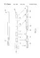
- FIG. 3is a schematic illustration of a packet transmitted with interrupt indication bits, in accordance with a preferred embodiment of the invention.
- FIG. 4is a schematic flowchart of the actions performed by a receiver, in accordance with a preferred embodiment of the present invention.
- FIG. 1is a schematic illustration of a system 20 for transmitting packets, in accordance with a preferred embodiment of the invention.
- System 20is preferably part of a packet based communication network.
- FIG. 1shows a transmitter 22 , a receiver 28 and a link 26 connecting the transmitter and receiver.
- the distinction between the transmitter and receiveris for clarity of the following explanation.
- both transmitter 22 and receiver 28may receive and transmit packets.
- transmitter 22 and receiver 28are of a substantially identical structure.
- Link 26preferably comprises a single channel which allows transmission of only a single data bit at any specific time.
- Transmitter 22preferably comprises an input buffer 24 for regular packets and an urgent buffer 25 for urgent packets, such as real time audio packets, control messages and echo packets of keyboard strokes. Transmitter 22 further comprises an interrupt handler 36 which receives packets from buffers 24 and 25 and prepares them for transmission, the operation of the interrupt handler is described below. Interrupt handler 36 is preferably associated with at least one stack 37 for storing control data relating to interrupted packets. From the interrupt handler the packets are passed to a low layer unit 32 , for example an HDLC handler, which prepares the packets for transmission on link 26 according to the specific type of the link.
- a low layer unit 32for example an HDLC handler
- low layer unit 32passes the packets to a modem 34 , or to another physical layer unit, which transmits the bits of the packet to receiver 28 .
- receiver 28preferably comprises a modem 34 ′, a low layer unit 32 ′, an interrupt handler 36 ′ and output buffers 24 ′ and 25 ′.
- receiver 28comprises only a single output buffer.
- FIG. 2is a flowchart of the actions performed by interrupt handler 36 of transmitter 22 , in accordance with a preferred embodiment of the present invention.
- FIG. 3is a schematic illustration of a packet transmitted by transmitter 22 in various stages, in accordance with a preferred embodiment of the present invention.
- interrupt handler 36checks ( 60 ) whether there are any urgent packets to be transmitted. If there are urgent packets they are transmitted ( 59 ) before any of the regular packets in buffer 24 . If there are no urgent packets to be transmitted, interrupt handler 36 receives a regular packet 40 (if one exists), including a header 42 , from buffer 24 and passes ( 61 , 62 and 63 ) the bits of the packet serially to low layer unit 32 . At predefined stop points 44 throughout packet 40 , interrupt handler 36 preferably checks ( 64 ) whether an urgent packet has been received. If no urgent packet was received, interrupt handler 36 passes ( 66 ) for transmission a set of bits 46 (for example “000” as in FIG.
- interrupt handler 36stores ( 68 ) control data related to the packet on stack 37 , while the rest of packet 40 is preferably withheld in input buffer 24 .
- interrupt handler 36preferably passes ( 70 ) for transmission a set of one or more interrupt indication bits 48 (“111” in FIG. 3) which indicate that an interrupt is declared.
- interrupt handler 36immediately begins to pass ( 72 ) for transmission the bits of the urgent packet.
- interrupt handler 36retrieves ( 74 ) the control data of the interrupted packet 40 from stack 37 and continues streaming the bits of packet 40 from input buffer 24 to low layer unit 32 , preferably, together with periodically added sets of bits 46 .
- packet 40is retransmitted in its entirety.
- FIG. 4is a flowchart of the actions performed by receiver 28 , in accordance with a preferred embodiment of the present invention.
- Bits transmitted over link 26are received ( 80 ) by modem 34 ′ and low layer unit 32 ′ and are passed to interrupt handler 36 ′.
- interrupt handler 36 ′examines ( 84 ) the received set of bits which indicates whether an interrupt is declared.
- the set of bits ( 46 or 48 )is preferably removed ( 82 ) from the stream of bits. If the set of bits indicates that no interrupt is declared (set 46 ), interrupt handler 36 ′ continues receiving the bits as usual.
- interrupt handler 36 ′saves ( 86 ) the packet being received on stack 37 ′, preferably together with related control data, and begins receiving ( 88 ) the interrupting packet.
- interrupt handler 36 ′checks the header of the interrupting packet for the length of the packet in order to know when the interrupting packet is finished. When the interrupting packet has been entirely received, interrupt handler 36 ′ retrieves ( 90 ) the interrupted packet from stack 37 ′ and adds the subsequently received bits to the interrupted packet.
- stop points 44are located at fixed intervals of a predetermined number of bits. Minimizing the maximal delay incurred on an urgent packet requires making stop points 44 as frequent as possible. On the other hand frequently transmitting bit sets 46 incurs additional traffic on link 26 . Therefore, the length of the fixed intervals is determined as a compromise between minimizing the maximal delay on urgent packets and minimizing the overhead traffic.
- the fixed intervals of stop points 44begin at the beginning of each packet 40 .
- the fixed intervalsbegin after headers 42 of the packets, such that interrupts cannot be declared within the header of a packet.
- the fixed intervalsare continuously counted over packets, preferably, until an urgent packet is encountered.
- stop points 44are not defined within a predetermined interval from the end of the transmitted packets.
- stop points 44are placed in accordance with a predetermined series of intervals.
- the intervals between stop points 44increase with the progression of the packet, such that the stop points are more frequent at the beginning of the packet than at the end of the packet.
- the system manager of system 20sets the locations of stop points 44 based on parameters of the system, such as the urgency level of the urgent packets, the occurrence rate of urgent packets, and the traffic load on link 26 .
- a managing processor of system 20sets the locations of stop points 44 automatically based on measurements of the above parameters and/or other parameters of system 20 .
- the managing processorsets the rules of determining the locations of stop points 44 each time link 26 is brought up.
- the managing processorsets the rules determining the locations of stop points 44 periodically, for example, every 15-30 minutes.
- the managing processorsends the determined rules to both transmitter 22 and receiver 28 , and preferably allows the new rules to come into effect only after confirmation has been received from both the transmitter and the receiver.
- the rules for determining the locations of stop points 44vary with parameters of system 20 , such as the connectivity of system 20 , e.g., failure of links within the system.
- the rulesdepend on parameters external to system 20 , such as the time of day, which in some systems is indicative of the urgency level and/or the occurrence rate of urgent packets.
- the locations of stop points 44are indicated by information in the header of the transmitted packet.
- the header of the packetdoes not include stop points or includes stop points at fixed points which do not change responsive to the contents of the header.
- receiver 28When receiver 28 receives a new packet it immediately reads the header to determine the locations of the stop points in receiving the rest of the packet.
- the locations of stop points 44depend on the source and/or destination of the packet. In some systems, the source and/or destination are indicative of the urgency level and/or occurrence rate of urgent packets and/or of other parameters of the system. Alternatively or additionally, the locations of stop points 44 depend on the length of packet 40 . In a preferred embodiment, short packets do not include stop points 44 while long packets include frequent stop points. Further alternatively or additionally, header 42 includes explicit indication of the locations of stop points 44 .
- stop points 44are set according to knowledge on when urgent packets are expected. For example, if the urgent packets comprise real time audio data, the packets are usually generated at fixed intervals. Therefore, stop points 44 are preferably set such that an interrupt may be declared immediately after receiving an urgent packet.
- no stop points 44are defined and no interrupts are allowed.
- packets transmitted to receivers which do not recognize interruptspreferably do not include stop points.
- transmitter 22preferably checks with receiver 28 whether it recognizes interrupts. If it does not recognize interrupts all the packets sent to receiver 28 are sent without adding indication bits.
- the inserted indication bitsare transparent to external units. That is, once the indication bits are removed by receiver 28 , there is no way for a third unit receiving a packet from the receiver to know whether the received packet was interrupted or whether interrupt indication bits were inserted to the packet.
- the same number of bitsis used to declare an interrupt and to indicate that an interrupt is not declared.
- a fixed number of bitspreferably between three to five bits, are inserted in each stop point.
- the distance between the “interrupt” and “no interrupt” bit setsis as large as possible in order to allow for determining which of sets 46 and 48 was received even when errors have occurred during the transmission of the indication bits. Immunity to transmission errors is more important in the indication bits than in regular bits since the implications of a mistake in determining what is indicated by the indication bits goes beyond the boundaries of a single packet.
- a single bitis used in each stop point 44 to notify whether an interrupt is declared.
- receiver 28when receiver 28 determines from the inserted set of bits ( 46 or 48 ) that an interrupt was declared, it checks the interrupting packet for a standard packet structure to make sure that there was no mistake in receiving the inserted set of bits ( 46 or 48 ). For example, receiver 28 preferably checks that the interrupting packet has a header in accordance with a standard header form.
- the “no interrupt” bit setis shorter than the “interrupt” bit set since the interrupt bit set generally appears more often.
- a single ‘0’ bitis used to indicate that no interrupt is declared, while a long set of bits, e.g., 16 bits, beginning with a ‘1’, is used to declare an interrupt.
- bitsare added at a stop point 44 only if an interrupt is declared.
- the number of added bitsis large enough to make marginally small the possibility that the specific sequence used to declare an interrupt appears in the stop point by chance.
- bitsare added to indicate an interrupt at any point along packet 40 and no stop points 44 are defined, preferably using a code which does not appear in normal packets.
- the urgent packetis not inserted immediately after the interrupt indication bits. Instead, the urgent packet is inserted a fixed number of bits after the interrupt indication bits.
- urgent buffer 25notifies interrupt handler 36 that an urgent packet has been received before a header is prepared for the urgent packet. If a stop point is encountered between receiving notification of a received urgent packet and actually receiving the packet, interrupt handler 36 may insert indication bits to the stop point under the knowledge that the urgent packet will be available for transmission by the time it is to be transmitted.
- transmitter 22when transmitter 22 receives an urgent packet before the next stop point (especially when the next stop point is still far away), the transmitter begins transmitting the urgent packet before the stop point is reached. At the stop point, transmitter 22 indicates where the transmission of the urgent packet began. Preferably, transmitter 22 interrupts the current packet only if there is a substantial part of the packet which was not transmitted yet. In a preferred embodiment, transmitter 22 interrupts the current packet only if the current packet includes non-transmitted bits at least up to the next stop point. Thus, receiver 28 does not examine the contents of the transmitted bits, under the wrong assumption that the bits belong to the interrupted packet, before the stop point with the notification of the interrupt is reached.
- an additional set of bitsindicates the exact location where the transmission of the urgent packet began.
- the stop pointsare located at intervals of 256 bits and the additional set of bits comprises a set of eight bits which indicates the displacement from the stop point to the location where the transmission of the urgent packet began.
- the additional set of bitscomprises four bits which are multiplied by a factor of sixteen to receive the displacement. In this example, the beginning of transmitting the urgent packet is allowed only every sixteen bits.
- the displacementmay be stated as a positive number which states the displacement in one direction, or as a signed number which may indicate the displacement both in forward and backward directions.
- the bits inserted at stop points 44may have more than two predetermined codes.
- the inserted bitsmay have a few different codes for indicating that an interrupt is declared. These codes preferably differ in the placement for inserting the urgent packet. For example, a first code may indicate that the urgent packet follows immediately, a second code indicates that the urgent packet follows after 20 more bits of original packet 40 and a third code indicates that the urgent packet follows after 40 more bits of original packet 40 .
- the intervals between stop points 44may be made larger without increasing the delay of urgent packets.
- the maximal number of interrupts allowed within a single packetis limited to a predetermined number, so that normal packets do not suffer too much delay due to the interrupts.
- the maximal number of allowed interruptsvaries.
- header 42indicates, implicitly or explicitly, the maximal number of allowed interrupts in the packet 40 .
- the number of allowed interrupts in a packetvary according to the time of day and/or according to information related to system 20 .
- termination bits having a specific codeare added after the urgent packet.
- these termination bitsare used in addition to, or instead of, the length field in the header of the urgent packet.
- an interrupt headeris inserted before the urgent packet identifying the transmission as an interrupt, and giving its length.
- a stop pointis defined immediately after the end of urgent packet 50 .
- preferred embodiments of the present inventionmay also be implemented in a system with many urgency levels.
- packets with an urgency level higher than the currently transmitted packetinterrupt the currently transmitted packet.
- stop pointsare defined also in the interrupting packets (if they are long) such that interrupts may be declared also in interrupting packets.
- stack 37is capable of storing a plurality of nested packets.
- transmitter 22preferably comprises a plurality of buffers for the different urgency levels.
- transmitter 22comprises a single addressable buffer which receives all the packets together with indication of their priority.
- transmitter 22 and/or receiver 28may include higher layer units which are located above buffers 24 , 25 , 24 ′ and 25 ′. Such higher layer units preferably operate exactly as if interrupt handler 36 was not located within the transmitter. Alternatively, the higher layer units are located between interrupt handler 36 and buffers 24 and 25 or between interrupt handler 36 and low layer unit 32 . In these alternatives the higher layer units are preferably altered to accommodate the existence of interrupt handler 36 .
- interrupt handler 36is formed as an integral part of low layer unit 32 . Further alternatively, interrupt handler 36 is located between low layer unit 32 and modem 34 . In such a case, the signals transmitted on link 26 violate the standards of the low layer, because of the inserted sets of indication bits. However, since the transmitter and receiver have compatible interrupt handlers 36 no problems are caused due to such violation.
- Interrupt handler 36 and low layer 32are preferably implemented in software on a single processor. Alternatively, one or both of interrupt handler 36 and low layer 32 are implemented on separate processors or in dedicated hardware.
- transmitter 22also includes a MAC unit or other layer 2 unit of the TCP/IP protocol suite.
- interruptsare declared by inserting bits into the stream of data bits
- interruptsare declared using other methods, for example using a dedicated transmission path parallel to link 26 .
- the dedicated transmission pathcarries a binary signal which indicates whether an interrupt is being declared.
- the urgent packetbegins at a next stop point within the stream of data.
- the urgent packetbegins immediately and no stop points are predefined.
Landscapes
- Engineering & Computer Science (AREA)
- Computer Networks & Wireless Communication (AREA)
- Signal Processing (AREA)
- Data Exchanges In Wide-Area Networks (AREA)
- Communication Control (AREA)
Abstract
Description
Claims (25)
Priority Applications (3)
| Application Number | Priority Date | Filing Date | Title |
|---|---|---|---|
| US09/411,287US6631132B1 (en) | 1999-10-04 | 1999-10-04 | Urgent packet transmission |
| PCT/IL2000/000598WO2001026326A1 (en) | 1999-10-04 | 2000-09-26 | Urgent packet transmission |
| AU75515/00AAU7551500A (en) | 1999-10-04 | 2000-09-26 | Urgent packet transmission |
Applications Claiming Priority (1)
| Application Number | Priority Date | Filing Date | Title |
|---|---|---|---|
| US09/411,287US6631132B1 (en) | 1999-10-04 | 1999-10-04 | Urgent packet transmission |
Publications (1)
| Publication Number | Publication Date |
|---|---|
| US6631132B1true US6631132B1 (en) | 2003-10-07 |
Family
ID=23628330
Family Applications (1)
| Application Number | Title | Priority Date | Filing Date |
|---|---|---|---|
| US09/411,287Expired - LifetimeUS6631132B1 (en) | 1999-10-04 | 1999-10-04 | Urgent packet transmission |
Country Status (3)
| Country | Link |
|---|---|
| US (1) | US6631132B1 (en) |
| AU (1) | AU7551500A (en) |
| WO (1) | WO2001026326A1 (en) |
Cited By (20)
| Publication number | Priority date | Publication date | Assignee | Title |
|---|---|---|---|---|
| US20010021984A1 (en)* | 2000-03-09 | 2001-09-13 | Lg Electronics Inc. | Apparatus and method for re-transmitting erroneous packet data |
| US20020051466A1 (en)* | 2000-07-27 | 2002-05-02 | Orckit Communications Ltd. | Dynamic packet fragmentation |
| US20020131425A1 (en)* | 2001-01-08 | 2002-09-19 | Rafi Shalom | Packet fragmentation with nested interruptions |
| US20020167945A1 (en)* | 2000-11-22 | 2002-11-14 | Yeshik Shin | Method and system for packet ordering based on packet type |
| US20030009765A1 (en)* | 2001-06-22 | 2003-01-09 | Linden Thomas M. | Multiple program burst broadcast |
| US20030110281A1 (en)* | 2001-12-06 | 2003-06-12 | Linden Minnick | Method and apparatus for processing latency sensitive electronic data with interrupt moderation |
| US20040192252A1 (en)* | 2003-03-31 | 2004-09-30 | Naveen Aerrabotu | Emergency packet data network communication system and call features |
| US20050068951A1 (en)* | 2003-09-29 | 2005-03-31 | Alain Rivard | Protocol for video communications and camera control |
| US20060221875A1 (en)* | 2005-03-31 | 2006-10-05 | Intel Corporation | Network interface with transmit frame descriptor reuse |
| US20070047443A1 (en)* | 2005-08-25 | 2007-03-01 | P.A. Semi, Inc. | Channelized flow control |
| US20070047572A1 (en)* | 2005-08-25 | 2007-03-01 | P.A. Semi, Inc. | Explicit flow control in Gigabit/10 Gigabit Ethernet system |
| US20070127372A1 (en)* | 2005-12-06 | 2007-06-07 | Shabbir Khan | Digital object routing |
| US20070133553A1 (en)* | 2005-12-06 | 2007-06-14 | Shabbir Kahn | System and/or method for downstream bidding |
| US20070133710A1 (en)* | 2005-12-06 | 2007-06-14 | Shabbir Khan | Digital object title and transmission information |
| US20080069094A1 (en)* | 2006-09-19 | 2008-03-20 | Samsung Electronics Co., Ltd. | Urgent packet latency control of network on chip (NOC) apparatus and method of the same |
| US20100158047A1 (en)* | 2008-12-23 | 2010-06-24 | Samsung Electronics Co., Ltd. | Urgent packet transmission/reception apparatus and method for digital broadcast system |
| US8014389B2 (en) | 2005-12-06 | 2011-09-06 | Lippershy Celestial Llc | Bidding network |
| US20120170591A1 (en)* | 2010-12-30 | 2012-07-05 | Broadcom Corporation | Advanced and Dynamic Physical Layer Device Capabilities Utilizing a Link Interruption Signal |
| US20130100805A1 (en)* | 2010-06-25 | 2013-04-25 | Siemens Aktiengesellschaft | Prioritized transfer of data telegrams |
| US9686183B2 (en) | 2005-12-06 | 2017-06-20 | Zarbaña Digital Fund Llc | Digital object routing based on a service request |
Families Citing this family (5)
| Publication number | Priority date | Publication date | Assignee | Title |
|---|---|---|---|---|
| US7224703B2 (en) | 2001-12-12 | 2007-05-29 | Telefonaktiebolaget Lm Ericsson (Publ) | Method and apparatus for segmenting a data packet |
| WO2004056064A1 (en)* | 2002-12-17 | 2004-07-01 | Bob Tang | Early despatch of packet header to overcome transmission latency when sending video or audio over the internet |
| FR2851708B1 (en)* | 2003-02-24 | 2005-05-27 | At & T Corp | METHOD FOR TRANSMITTING HIGH PRIORITY PACKETS IN AN IP TRANSMISSION NETWORK |
| US7339893B2 (en)* | 2003-03-18 | 2008-03-04 | Cisco Technology, Inc. | Pre-empting low-priority traffic with high-priority traffic on a dedicated link |
| CN1307845C (en)* | 2004-07-29 | 2007-03-28 | Ut斯达康通讯有限公司 | Dynamic flow control method based on paging zone |
Citations (16)
| Publication number | Priority date | Publication date | Assignee | Title |
|---|---|---|---|---|
| EP0684719A1 (en) | 1994-05-25 | 1995-11-29 | International Business Machines Corporation | Method and apparatus for transmission of high priority traffic on low speed communication links |
| US5497371A (en) | 1993-10-26 | 1996-03-05 | Northern Telecom Limited | Digital telecommunication link for efficiently transporting mixed classes of packets |
| US5689509A (en)* | 1995-07-07 | 1997-11-18 | Sun Microsystems, Inc. | Apparatus and method for packetizing and segmenting MPEG packets |
| US5768273A (en)* | 1995-04-05 | 1998-06-16 | International Business Machines Corporation | Method and apparatus for priority level queueing in processing ATM cell header and payload |
| US5802051A (en)* | 1996-06-10 | 1998-09-01 | Telefonaktiebolaget Lm Ericsson | Multiplexing of voice and data minicells |
| US5870394A (en)* | 1996-07-23 | 1999-02-09 | Northern Telecom Limited | Method and apparatus for reassembly of data packets into messages in an asynchronous transfer mode communications system |
| US5956341A (en) | 1996-12-13 | 1999-09-21 | International Business Machines Corporation | Method and system for optimizing data transmission line bandwidth occupation in a multipriority data traffic environment |
| US5999534A (en)* | 1996-12-26 | 1999-12-07 | Daewoo Electronics Co., Ltd. | Method and apparatus for scheduling cells for use in a static priority scheduler |
| US6154459A (en)* | 1997-07-11 | 2000-11-28 | Telefonaktiebolaget Lm Ericsson | Data shaper for ATM traffic |
| US6256315B1 (en)* | 1998-10-27 | 2001-07-03 | Fujitsu Network Communications, Inc. | Network to network priority frame dequeuing |
| US6272109B1 (en)* | 1997-11-18 | 2001-08-07 | Cabletron Systems, Inc. | Hierarchical schedules for different ATM traffic |
| US20010015985A1 (en)* | 1996-10-22 | 2001-08-23 | Petrus A.M. Van Grinsven | Transmission system with flexible frame structure |
| US6411617B1 (en)* | 1998-12-10 | 2002-06-25 | Nokia Telecommunications, Oy | System and method for managing data traffic associated with various quality of service principles using a conventional network node switch |
| US6466578B1 (en)* | 1996-11-29 | 2002-10-15 | Nortel Networks Limited | Scaleable data network router |
| US6466580B1 (en)* | 1999-02-23 | 2002-10-15 | Advanced Micro Devices, Inc. | Method and apparatus for processing high and low priority frame data transmitted in a data communication system |
| US6487171B1 (en)* | 1999-05-19 | 2002-11-26 | 3Com Corporation | Crossbar switching matrix with broadcast buffering |
- 1999
- 1999-10-04USUS09/411,287patent/US6631132B1/ennot_activeExpired - Lifetime
- 2000
- 2000-09-26WOPCT/IL2000/000598patent/WO2001026326A1/enactiveApplication Filing
- 2000-09-26AUAU75515/00Apatent/AU7551500A/ennot_activeAbandoned
Patent Citations (16)
| Publication number | Priority date | Publication date | Assignee | Title |
|---|---|---|---|---|
| US5497371A (en) | 1993-10-26 | 1996-03-05 | Northern Telecom Limited | Digital telecommunication link for efficiently transporting mixed classes of packets |
| EP0684719A1 (en) | 1994-05-25 | 1995-11-29 | International Business Machines Corporation | Method and apparatus for transmission of high priority traffic on low speed communication links |
| US5768273A (en)* | 1995-04-05 | 1998-06-16 | International Business Machines Corporation | Method and apparatus for priority level queueing in processing ATM cell header and payload |
| US5689509A (en)* | 1995-07-07 | 1997-11-18 | Sun Microsystems, Inc. | Apparatus and method for packetizing and segmenting MPEG packets |
| US5802051A (en)* | 1996-06-10 | 1998-09-01 | Telefonaktiebolaget Lm Ericsson | Multiplexing of voice and data minicells |
| US5870394A (en)* | 1996-07-23 | 1999-02-09 | Northern Telecom Limited | Method and apparatus for reassembly of data packets into messages in an asynchronous transfer mode communications system |
| US20010015985A1 (en)* | 1996-10-22 | 2001-08-23 | Petrus A.M. Van Grinsven | Transmission system with flexible frame structure |
| US6466578B1 (en)* | 1996-11-29 | 2002-10-15 | Nortel Networks Limited | Scaleable data network router |
| US5956341A (en) | 1996-12-13 | 1999-09-21 | International Business Machines Corporation | Method and system for optimizing data transmission line bandwidth occupation in a multipriority data traffic environment |
| US5999534A (en)* | 1996-12-26 | 1999-12-07 | Daewoo Electronics Co., Ltd. | Method and apparatus for scheduling cells for use in a static priority scheduler |
| US6154459A (en)* | 1997-07-11 | 2000-11-28 | Telefonaktiebolaget Lm Ericsson | Data shaper for ATM traffic |
| US6272109B1 (en)* | 1997-11-18 | 2001-08-07 | Cabletron Systems, Inc. | Hierarchical schedules for different ATM traffic |
| US6256315B1 (en)* | 1998-10-27 | 2001-07-03 | Fujitsu Network Communications, Inc. | Network to network priority frame dequeuing |
| US6411617B1 (en)* | 1998-12-10 | 2002-06-25 | Nokia Telecommunications, Oy | System and method for managing data traffic associated with various quality of service principles using a conventional network node switch |
| US6466580B1 (en)* | 1999-02-23 | 2002-10-15 | Advanced Micro Devices, Inc. | Method and apparatus for processing high and low priority frame data transmitted in a data communication system |
| US6487171B1 (en)* | 1999-05-19 | 2002-11-26 | 3Com Corporation | Crossbar switching matrix with broadcast buffering |
Cited By (35)
| Publication number | Priority date | Publication date | Assignee | Title |
|---|---|---|---|---|
| US20010021984A1 (en)* | 2000-03-09 | 2001-09-13 | Lg Electronics Inc. | Apparatus and method for re-transmitting erroneous packet data |
| US7149181B2 (en)* | 2000-03-09 | 2006-12-12 | Lg Electronics Inc. | Apparatus and method for re-transmitting erroneous packet data |
| US20020051466A1 (en)* | 2000-07-27 | 2002-05-02 | Orckit Communications Ltd. | Dynamic packet fragmentation |
| US6891855B2 (en) | 2000-07-27 | 2005-05-10 | Corrigent Systems, Ltd. | Dynamic packet fragmentation |
| US20020167945A1 (en)* | 2000-11-22 | 2002-11-14 | Yeshik Shin | Method and system for packet ordering based on packet type |
| US7154905B2 (en) | 2000-11-22 | 2006-12-26 | Silicon Image | Method and system for nesting of communications packets |
| US20040004975A1 (en)* | 2000-11-22 | 2004-01-08 | Yeshik Shin | Method and system for nesting of communications packets |
| US6876669B2 (en)* | 2001-01-08 | 2005-04-05 | Corrigent Systems Ltd. | Packet fragmentation with nested interruptions |
| US20020131425A1 (en)* | 2001-01-08 | 2002-09-19 | Rafi Shalom | Packet fragmentation with nested interruptions |
| US20030009765A1 (en)* | 2001-06-22 | 2003-01-09 | Linden Thomas M. | Multiple program burst broadcast |
| US20030110281A1 (en)* | 2001-12-06 | 2003-06-12 | Linden Minnick | Method and apparatus for processing latency sensitive electronic data with interrupt moderation |
| US8856416B2 (en)* | 2001-12-06 | 2014-10-07 | Intel Corporation | Method and apparatus for processing latency sensitive electronic data with interrupt moderation |
| US20040192252A1 (en)* | 2003-03-31 | 2004-09-30 | Naveen Aerrabotu | Emergency packet data network communication system and call features |
| US20050068951A1 (en)* | 2003-09-29 | 2005-03-31 | Alain Rivard | Protocol for video communications and camera control |
| US20060221875A1 (en)* | 2005-03-31 | 2006-10-05 | Intel Corporation | Network interface with transmit frame descriptor reuse |
| US7551638B2 (en)* | 2005-03-31 | 2009-06-23 | Intel Corporation | Network interface with transmit frame descriptor reuse |
| US20070047443A1 (en)* | 2005-08-25 | 2007-03-01 | P.A. Semi, Inc. | Channelized flow control |
| US20070047572A1 (en)* | 2005-08-25 | 2007-03-01 | P.A. Semi, Inc. | Explicit flow control in Gigabit/10 Gigabit Ethernet system |
| US20100188980A1 (en)* | 2005-08-25 | 2010-07-29 | Desai Shailendra S | Explicit Flow Control in a Gigabit/10 Gigabit Ethernet System |
| US20070127372A1 (en)* | 2005-12-06 | 2007-06-07 | Shabbir Khan | Digital object routing |
| US8194701B2 (en) | 2005-12-06 | 2012-06-05 | Lippershy Celestial Llc | System and/or method for downstream bidding |
| US12047270B2 (en) | 2005-12-06 | 2024-07-23 | Zarbaña Digital Fund Llc | Digital object routing based on a service request |
| US20070133710A1 (en)* | 2005-12-06 | 2007-06-14 | Shabbir Khan | Digital object title and transmission information |
| US7894447B2 (en) | 2005-12-06 | 2011-02-22 | Lippershy Celestial Llc | Digital object routing |
| US8014389B2 (en) | 2005-12-06 | 2011-09-06 | Lippershy Celestial Llc | Bidding network |
| US8055897B2 (en)* | 2005-12-06 | 2011-11-08 | Lippershy Celestial Llc | Digital object title and transmission information |
| US11539614B2 (en) | 2005-12-06 | 2022-12-27 | Zarbaña Digital Fund Llc | Digital object routing based on a service request |
| US10892975B2 (en) | 2005-12-06 | 2021-01-12 | Zarbaña Digital Fund Llc | Digital object routing based on a service request |
| US9686183B2 (en) | 2005-12-06 | 2017-06-20 | Zarbaña Digital Fund Llc | Digital object routing based on a service request |
| US20070133553A1 (en)* | 2005-12-06 | 2007-06-14 | Shabbir Kahn | System and/or method for downstream bidding |
| US20080069094A1 (en)* | 2006-09-19 | 2008-03-20 | Samsung Electronics Co., Ltd. | Urgent packet latency control of network on chip (NOC) apparatus and method of the same |
| US20100158047A1 (en)* | 2008-12-23 | 2010-06-24 | Samsung Electronics Co., Ltd. | Urgent packet transmission/reception apparatus and method for digital broadcast system |
| US20130100805A1 (en)* | 2010-06-25 | 2013-04-25 | Siemens Aktiengesellschaft | Prioritized transfer of data telegrams |
| US8665895B2 (en)* | 2010-12-30 | 2014-03-04 | Broadcom Corporation | Advanced and dynamic physical layer device capabilities utilizing a link interruption signal |
| US20120170591A1 (en)* | 2010-12-30 | 2012-07-05 | Broadcom Corporation | Advanced and Dynamic Physical Layer Device Capabilities Utilizing a Link Interruption Signal |
Also Published As
| Publication number | Publication date |
|---|---|
| AU7551500A (en) | 2001-05-10 |
| WO2001026326A1 (en) | 2001-04-12 |
Similar Documents
| Publication | Publication Date | Title |
|---|---|---|
| US6631132B1 (en) | Urgent packet transmission | |
| US6876669B2 (en) | Packet fragmentation with nested interruptions | |
| US5361372A (en) | Memory management for data transmission networks | |
| US7352695B2 (en) | Switch and a switching method | |
| KR100949245B1 (en) | 3G Congestion indication method in wireless access network | |
| US7558269B2 (en) | Method for transmitting high-priority packets in an IP transmission network | |
| JP2577539B2 (en) | bridge | |
| KR100316295B1 (en) | Packet management device for high speed packet network | |
| US6208650B1 (en) | Circuit for performing high-speed, low latency frame relay switching with support for fragmentation and reassembly and channel multiplexing | |
| EP0684719A1 (en) | Method and apparatus for transmission of high priority traffic on low speed communication links | |
| EP0582537A2 (en) | Transmission of high-priority, real-time traffic on low-speed communications links | |
| EP0224895A2 (en) | Data communication method and apparatus using multiple physical data links | |
| US20030112819A1 (en) | Communications interface for providing a plurality of communication channels to a single port on a processor | |
| EP0769863B1 (en) | Bridging apparatus for traffic filtering in communication networks | |
| US6952739B2 (en) | Method and device for parameter independent buffer underrun prevention | |
| EP0685951A2 (en) | Line interface devices for fast-packet networks | |
| US6700876B1 (en) | Congestion monitoring and message flow control in a blocking network | |
| CN114826495B (en) | Method for reducing NR, RLC, AM fragment loss report overhead | |
| CN102487330B (en) | Method and device for sending operation, administration and maintenance messages | |
| EP0899899B1 (en) | An apparatus and method for sharing a signaling channel | |
| JPH11196088A (en) | Multicast communication method and system | |
| GB2355374A (en) | Packet forwarding device with selective packet discarding when paused | |
| CN113273149A (en) | Data sending method and device and FlexE exchange system | |
| US6674770B1 (en) | Bit stuffing for synchronous HDLC | |
| JP2510875B2 (en) | Traffic monitoring system |
Legal Events
| Date | Code | Title | Description |
|---|---|---|---|
| AS | Assignment | Owner name:ECI TELECOM LTD., ISRAEL Free format text:ASSIGNMENT OF ASSIGNORS INTEREST;ASSIGNOR:SOURANI, SASON;REEL/FRAME:010306/0486 Effective date:19991003 | |
| AS | Assignment | Owner name:VERAZ NETWORKS LTD., ISRAEL Free format text:ASSIGNMENT OF ASSIGNORS INTEREST;ASSIGNOR:ECI TELECOM LTD.;REEL/FRAME:014006/0881 Effective date:20021225 | |
| STCF | Information on status: patent grant | Free format text:PATENTED CASE | |
| FEPP | Fee payment procedure | Free format text:PAYOR NUMBER ASSIGNED (ORIGINAL EVENT CODE: ASPN); ENTITY STATUS OF PATENT OWNER: LARGE ENTITY | |
| FPAY | Fee payment | Year of fee payment:4 | |
| FPAY | Fee payment | Year of fee payment:8 | |
| AS | Assignment | Owner name:DIALOGIC NETWORKS (ISRAEL) LTD., ISRAEL Free format text:CHANGE OF NAME;ASSIGNOR:VERAZ NETWORKS LTD.;REEL/FRAME:026576/0056 Effective date:20101102 | |
| AS | Assignment | Owner name:OBSIDIAN, LLC, AS COLLATERAL AGENT, CALIFORNIA Free format text:SUPPLEMENTAL INTELLECTUAL PROPERTY SECURITY AGREEMENT;ASSIGNORS:DIALOGIC INC.;DIALOGIC CORPORATION;DIALOGIC NETWORKS (ISRAEL) LTD.;REEL/FRAME:027931/0001 Effective date:20120322 | |
| AS | Assignment | Owner name:DIALOGIC INC. (A DELAWARE CORPORATION), MASSACHUSE Free format text:PARTIAL RELEASE OF INTELLECTUAL PROPERTY SECURITY AGREEMENT;ASSIGNOR:OBSIDIAN, LLC;REEL/FRAME:030707/0111 Effective date:20130626 Owner name:DIALOGIC CORPORATION (A BRITISH COLUMBIA CORPORATI Free format text:PARTIAL RELEASE OF INTELLECTUAL PROPERTY SECURITY AGREEMENT;ASSIGNOR:OBSIDIAN, LLC;REEL/FRAME:030707/0111 Effective date:20130626 | |
| FEPP | Fee payment procedure | Free format text:PAYOR NUMBER ASSIGNED (ORIGINAL EVENT CODE: ASPN); ENTITY STATUS OF PATENT OWNER: LARGE ENTITY Free format text:PAYER NUMBER DE-ASSIGNED (ORIGINAL EVENT CODE: RMPN); ENTITY STATUS OF PATENT OWNER: LARGE ENTITY | |
| AS | Assignment | Owner name:CANTATA TECHNOLOGY, INC., NEW JERSEY Free format text:RELEASE BY SECURED PARTY;ASSIGNOR:OBSIDIAN, LLC;REEL/FRAME:034468/0654 Effective date:20141124 Owner name:DIALOGIC INC., NEW JERSEY Free format text:RELEASE BY SECURED PARTY;ASSIGNOR:OBSIDIAN, LLC;REEL/FRAME:034468/0654 Effective date:20141124 Owner name:DIALOGIC US HOLDINGS INC., NEW JERSEY Free format text:RELEASE BY SECURED PARTY;ASSIGNOR:OBSIDIAN, LLC;REEL/FRAME:034468/0654 Effective date:20141124 Owner name:SHIVA (US) NETWORK CORPORATION, NEW JERSEY Free format text:RELEASE BY SECURED PARTY;ASSIGNOR:OBSIDIAN, LLC;REEL/FRAME:034468/0654 Effective date:20141124 Owner name:DIALOGIC CORPORATION, F/K/A EICON NETWORKS CORPORA Free format text:RELEASE BY SECURED PARTY;ASSIGNOR:OBSIDIAN, LLC;REEL/FRAME:034468/0654 Effective date:20141124 Owner name:BROOKTROUT TECHNOLOGY, INC., NEW JERSEY Free format text:RELEASE BY SECURED PARTY;ASSIGNOR:OBSIDIAN, LLC;REEL/FRAME:034468/0654 Effective date:20141124 Owner name:EAS GROUP, INC., NEW JERSEY Free format text:RELEASE BY SECURED PARTY;ASSIGNOR:OBSIDIAN, LLC;REEL/FRAME:034468/0654 Effective date:20141124 Owner name:DIALOGIC DISTRIBUTION LIMITED, F/K/A EICON NETWORK Free format text:RELEASE BY SECURED PARTY;ASSIGNOR:OBSIDIAN, LLC;REEL/FRAME:034468/0654 Effective date:20141124 Owner name:DIALOGIC (US) INC., F/K/A DIALOGIC INC. AND F/K/A Free format text:RELEASE BY SECURED PARTY;ASSIGNOR:OBSIDIAN, LLC;REEL/FRAME:034468/0654 Effective date:20141124 Owner name:DIALOGIC MANUFACTURING LIMITED, F/K/A EICON NETWOR Free format text:RELEASE BY SECURED PARTY;ASSIGNOR:OBSIDIAN, LLC;REEL/FRAME:034468/0654 Effective date:20141124 Owner name:DIALOGIC RESEARCH INC., F/K/A EICON NETWORKS RESEA Free format text:RELEASE BY SECURED PARTY;ASSIGNOR:OBSIDIAN, LLC;REEL/FRAME:034468/0654 Effective date:20141124 Owner name:EXCEL SWITCHING CORPORATION, NEW JERSEY Free format text:RELEASE BY SECURED PARTY;ASSIGNOR:OBSIDIAN, LLC;REEL/FRAME:034468/0654 Effective date:20141124 Owner name:EXCEL SECURITIES CORPORATION, NEW JERSEY Free format text:RELEASE BY SECURED PARTY;ASSIGNOR:OBSIDIAN, LLC;REEL/FRAME:034468/0654 Effective date:20141124 Owner name:CANTATA TECHNOLOGY INTERNATIONAL, INC., NEW JERSEY Free format text:RELEASE BY SECURED PARTY;ASSIGNOR:OBSIDIAN, LLC;REEL/FRAME:034468/0654 Effective date:20141124 Owner name:DIALOGIC JAPAN, INC., F/K/A CANTATA JAPAN, INC., N Free format text:RELEASE BY SECURED PARTY;ASSIGNOR:OBSIDIAN, LLC;REEL/FRAME:034468/0654 Effective date:20141124 Owner name:BROOKTROUT NETWORKS GROUP, INC., NEW JERSEY Free format text:RELEASE BY SECURED PARTY;ASSIGNOR:OBSIDIAN, LLC;REEL/FRAME:034468/0654 Effective date:20141124 Owner name:SNOWSHORE NETWORKS, INC., NEW JERSEY Free format text:RELEASE BY SECURED PARTY;ASSIGNOR:OBSIDIAN, LLC;REEL/FRAME:034468/0654 Effective date:20141124 Owner name:BROOKTROUT SECURITIES CORPORATION, NEW JERSEY Free format text:RELEASE BY SECURED PARTY;ASSIGNOR:OBSIDIAN, LLC;REEL/FRAME:034468/0654 Effective date:20141124 | |
| REMI | Maintenance fee reminder mailed | ||
| FPAY | Fee payment | Year of fee payment:12 | |
| SULP | Surcharge for late payment | Year of fee payment:11 |