US6631016B1 - Full-parallax holographic stereograms on curved substrates - Google Patents
Full-parallax holographic stereograms on curved substratesDownload PDFInfo
- Publication number
- US6631016B1 US6631016B1US09/908,828US90882801AUS6631016B1US 6631016 B1US6631016 B1US 6631016B1US 90882801 AUS90882801 AUS 90882801AUS 6631016 B1US6631016 B1US 6631016B1
- Authority
- US
- United States
- Prior art keywords
- substrate
- hogel
- tile
- orientation
- cylindrical
- Prior art date
- Legal status (The legal status is an assumption and is not a legal conclusion. Google has not performed a legal analysis and makes no representation as to the accuracy of the status listed.)
- Expired - Lifetime
Links
Images


Classifications
- G—PHYSICS
- G03—PHOTOGRAPHY; CINEMATOGRAPHY; ANALOGOUS TECHNIQUES USING WAVES OTHER THAN OPTICAL WAVES; ELECTROGRAPHY; HOLOGRAPHY
- G03H—HOLOGRAPHIC PROCESSES OR APPARATUS
- G03H1/00—Holographic processes or apparatus using light, infrared or ultraviolet waves for obtaining holograms or for obtaining an image from them; Details peculiar thereto
- G03H1/26—Processes or apparatus specially adapted to produce multiple sub- holograms or to obtain images from them, e.g. multicolour technique
- G03H1/268—Holographic stereogram
- G—PHYSICS
- G03—PHOTOGRAPHY; CINEMATOGRAPHY; ANALOGOUS TECHNIQUES USING WAVES OTHER THAN OPTICAL WAVES; ELECTROGRAPHY; HOLOGRAPHY
- G03H—HOLOGRAPHIC PROCESSES OR APPARATUS
- G03H1/00—Holographic processes or apparatus using light, infrared or ultraviolet waves for obtaining holograms or for obtaining an image from them; Details peculiar thereto
- G03H1/04—Processes or apparatus for producing holograms
- G03H1/0402—Recording geometries or arrangements
- G03H2001/043—Non planar recording surface, e.g. curved surface
- G—PHYSICS
- G03—PHOTOGRAPHY; CINEMATOGRAPHY; ANALOGOUS TECHNIQUES USING WAVES OTHER THAN OPTICAL WAVES; ELECTROGRAPHY; HOLOGRAPHY
- G03H—HOLOGRAPHIC PROCESSES OR APPARATUS
- G03H1/00—Holographic processes or apparatus using light, infrared or ultraviolet waves for obtaining holograms or for obtaining an image from them; Details peculiar thereto
- G03H1/26—Processes or apparatus specially adapted to produce multiple sub- holograms or to obtain images from them, e.g. multicolour technique
- G03H1/268—Holographic stereogram
- G03H2001/2685—One step recording process
- G—PHYSICS
- G03—PHOTOGRAPHY; CINEMATOGRAPHY; ANALOGOUS TECHNIQUES USING WAVES OTHER THAN OPTICAL WAVES; ELECTROGRAPHY; HOLOGRAPHY
- G03H—HOLOGRAPHIC PROCESSES OR APPARATUS
- G03H2270/00—Substrate bearing the hologram
- G03H2270/20—Shape
- G03H2270/21—Curved bearing surface
Definitions
- One-step hologram(including holographic stereogram) production technology has been used to satisfactorily record holograms in holographic recording materials without the traditional step of creating preliminary holograms.
- Both computer image holograms and non-computer image hologramsmay be produced by such one-step technology.
- computer processed images of objects or computer models of objectsallow the respective system to build a hologram from a number of contiguous, small, elemental pieces known as elemental holograms or hogels.
- an object beamis passed through the rendered image (e.g., as displayed on a spatial light modulator (SLM)) and used with a reference beam to create an interference pattern on the holographic recording material.
- SLMspatial light modulator
- hologramswith very wide viewing angles of 180°-360°.
- “wrapping” the hologram image on a curved substrate during the hologram recordingproduces images with a broad angle of view when the images are mounted on the curved substrate.
- Such hologramsenable viewing by a much larger audience than standard flat-format holograms.
- curved format hologramscan potentially improve the illusion of a suspended image, since the image is no longer anchored to a planar surface.
- the imagecan be made to appear at the radial center of the mounting substrate, either as a virtual (behind the hologram plane) or aerial (in front of the hologram plane) image.
- the image volumecan occupy any portion of the solid angle subtended by the intersection of the viewer's eyes and the hemi-cylinder 102 .
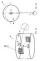
- the image(s) 104 incorporated in the reflection alcove hologram 100are typically computer-generated and processed graphics, and the hologram itself can be reconstructed with a standard white light source 106 placed above and centered relative to the hemi-cylinder 102 .
- the reflection alcove hologramcan produce imagery with a wide (up to 180°) viewing angle, a number of limitations are notable.
- FIGS. 1B and 1Cwhich show side and top views, respectively, of reflection alcove hologram 100
- the reference illumination angle from light source 108 for the reflection alcove hologram 100is fixed by the recording geometry, e.g., the angle of incidence of the reference beam with respect to the holographic recording material.
- Reflection alcove hologram 100is horizontal parallax-only, and each of the component strip holograms has a horizontal viewing angle of about 53°, as shown in FIG. 1 C.
- Reflection alcove hologram 100displays parallax in only the horizontal direction, and there is no apparent change in the position of an object with variations in the vertical viewpoint. Moreover, the same vertical image information is distributed across the entire 30° viewing angle (e.g., vertical viewing zones) for each of the hologram points 110 , 120 , and 130 . Thus, viewability and image information are severely limited by the recording geometry and techniques.
- the reflection alcove displayis also particularly sensitive to defects in the mounting substrate.
- the lack of vertical parallax between the image and the hologram surfaceplaces the image vertical focus at the hologram surface, and this impression is heightened by any cosmetic defects in the hologram or its substrate.
- Bentondescribes the possibility of producing multi-color imagery in the reflection alcove as a process requiring exposure in a single wavelength with tedious multiple emulsion swelling steps between, and carefully calibrated image processing for each step. This is due primarily to the existence of optical elements in the recording system that only function properly with the monochromatic laser light, including holographic optical elements (HOEs) and non-achromatic refractive optics.
- HOEsholographic optical elements
- the current inventioncomprises the recording of full parallax, one-step, full color holographic stereograms that can be mounted on a curved substrate after recording. It also comprises mounting the hologram on a substrate that is curved in on a substrate that can be curved in one or two dimensions, thereby producing any arbitrary shape.
- the hologramis comprised of one or more tiles, and thus curved holograms of unlimited size can be generated.
- the hologramis adaptable to a variety of curved substrates including hemi-cylindrical substrates with opaque backing to allow up to 180° of horizontal view zone, and full cylinders with transparent backing to allow viewing through 360° horizontally.
- the present inventionis a system for generating a holographic display on a curved substrate.
- the holographic displayincludes an image recorded on one or more tiles, and each tile is comprised of one or more holographic elements (hogels).
- the one or more tilesare mounted on the curved substrate.
- An image generation moduleis operable to allow a designer to specify a reference beam angle for each hogel and at least one of a radius of curvature for the substrate, a hogel orientation with respect to an image volume, a hogel orientation with respect to the substrate, and a hogel image orientation.
- the present inventionincludes a holographic display on a curved substrate comprised of a plurality of hogels recorded on the tile.
- the tileis mounted on the curved substrate.
- a plurality of hogelsare recorded on the tile by varying at least one of a hogel orientation with respect to an image volume, a hogel orientation with respect to the substrate, and a hogel image orientation.
- a method for generating a holographic display on a curved substrateincludes
- determining for each of the plurality of hogelsat least one of a hogel orientation with respect to an image volume, a hogel orientation with respect to the substrate, and a hogel image orientation based on the curvature of the substrate and the angle of illumination for the respective hogel.
- the shape of the substratecan be hemi-cylindrical, cylindrical, conical, or spherical. Other, irregularly shaped surfaces can also be used. In the case of hemi-cylindrical or cylindrical surface, another cylindrical section having a radius larger than the substrate can be positioned around the substrate to provide a background for the holographic display.
- the present inventionhas several advantages over alternative technologies.
- the present inventionachieves curved, full parallax holographic displays that provide more depth cues than displays currently available in the prior art.
- the present inventionalso provides holographic displays that can be viewed from a variety of viewpoints including over and under the imaged object, while removing depth limiting and potentially distorting astigmatism.
- the present inventioncan also produce full-color imagery without the need for tedious and difficult emulsion swelling, and triple exposures.
- the displaysare inherently scalable using tiling techniques disclosed in the '581 application in a manner similar to that for tiled flat format holograms.
- the ability in the current recording system to redirect the reference beam for each hogelmakes it possible to tailor the illumination angle and distance independently of the print or substrate geometry.
- each hogel in the current inventionhas over twice the viewing angle as the alcove case, enabling much larger images to be produced, and enabling visibility of the image over a much broader angle.
- FIG. 1Ais a front perspective view of an example of a reflection alcove hologram display.
- FIG. 1Bis a side view of a portion of a reflection alcove hologram display having a fixed illumination angle.
- FIG. 1Cis a top view of a portion of a reflection alcove hologram display having a fixed illumination angle.
- FIG. 2is a block diagram of components in a system for generating a holographic display on a curved substrate.
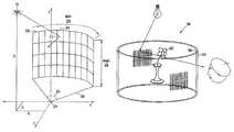
- FIG. 3is a perspective view showing parameters that can be specified for generating a tile with a plurality of hogels mounted on a curved substrate.
- FIG. 4Ais a side view of a portion of a hologram display having a variable illumination angle for each hogel in accordance with the present invention.
- FIG. 4Bis a top view of a hemi-cylindrical holographic display in accordance with the present invention.
- FIG. 5Ais a side perspective view of a cylindrical holographic display in accordance with the present invention.
- FIG. 5Bis a top view of a cylindrical holographic display in accordance with the present invention.
- the aforementioned '581 applicationdiscloses a mechanical-optical recording system and software capable of sequentially exposing multiple hologram elements (“hogels”) in, for example, a boustrophedontic fashion so as to produce a hogel array.
- These arrayscan reconstruct volumetric images with full parallax, and in full color.
- Large imagescan be composed of two or more hogel arrays that fit on one or more tiles. When more than one tile is used, each tile includes a portion of the overall image, providing a highly scalable system.
- a system 200 for producing hologramsincluding computer workstation 202 coupled to hologram printer 204 through network 206 .
- workstation 202may be one or more computers (e.g., high performance graphics workstations, servers, specialized computer graphics rendering computers, or typical personal computers) used alone, or in some combination to produce graphics images and printer control information used by printer 204 to produce holograms. Examples of workstation 202 and hologram printer 204 are described in the aforementioned '581 application.
- Workstation 202includes image generation module 212 for creating, importing, and manipulating images, as well as specifying hologram design parameters, that are used to produce the images for holograms created by printer 204 .
- image generation module 212includes capabilities for generating graphics images as well as importing images from other sources (e.g., other graphics software or files, and peripherals such as cameras and storage devices).
- the moduletypically includes software used for hologram layout and manufacturing.
- a tilecan be used as the basic unit for the hologram printing process.
- the size of a tile that can be processed by printer 214is generally limited by the size of the holographic recording material available.
- Finished hologramscan include one or more tiles with virtually any tile arrangement. Consequently image generation module 212 typically includes facilities for specifying one or more of the size, shape, orientation, and layout of the tile(s) used for the finished holographic display.
- Each tileis composed of many holographic elements (hogels), typically arranged in a two-dimensional array on the surface of the tile, but which can, in general, be arranged in any format.
- Each hogelis independently “recorded” by printer 204 as a hologram, i.e., an object beam passing through an SLM that includes a graphic image to be recorded is made to interfere with a reference beam. The interference pattern created is recorded in the holographic recording material.
- image generation module 212also includes facilities for specifying one or more of the size, shape, orientation, and layout of the hogels in a particularly tile. Additionally, one of the most important hogel features specified and/or determined in image generation module 212 is the reference beam angle for each hogel.
- Image generation module 212allows that angle to be specified in a variety of different ways.
- the reference beam anglecan be specified for each hogel independently.
- a light source location for a given tilecan be specified, and image generation module 212 then calculates the reference beam angle of incidence for each hogel based on one or more of the light source position, hogel location, image orientation, tile shape, and tile position.
- Printer 204is capable of generating full parallax, one-step, full color holographic stereograms as disclosed in the aforementioned '581 application using information received from image generation module 212 .
- image generation module 212allows a designer to specify image design parameters for each hogel in the array of hogels making up a tile. A designer can also specify parameters for each tile.
- Image generation module 212uses the design parameters to determine individual light intensities and directions for each hogel, based in part on the computer graphics image that forms the basis of the hologram to be recorded. This computation is independent of the orientation of each hogel so that the resultant imagery is properly displayed when the hologram is mounted on a curved substrate after recording.
- image generation module 212allows substrates to be curved in any dimension, thus having arbitrary, non-planar shapes.
- Printer control module 214receives instructions from image generation module 212 , and uses those instructions to control various aspects of printer 204 such as holographic recording material translation stages, SLMs, object and or reference beam steering devices, shutters, and other printer components as discussed in the '581 application.
- image generation module 212recognizes a list of commands, and uses a graphical user interface (GUI) that can include toolbars, menus, and other user interface features for creating and visualizing images.
- GUIgraphical user interface
- Image generation module 212includes components that allow a user to select, rotate, translate, scale, center, and interactively control the camera viewpoint through fly, zoom, and orbit modes. The user can change the appearance of images using, for example, fill mode, visibility, texture maps, and material property (e.g., transparency, reflectivity, and color) features.
- Image generation module 212also typically includes a camera editor that can be used in a design mode or a hologram printing mode.
- the camerarepresents a standard computer graphics pinhole camera.
- the usercan specify camera parameters such as type of view (e.g., birds eye, front, side), camera position, direction, positive or “up” direction, field of view, and the distance of near/far clip planes relative to a chosen coordinate system. More than one camera can,be created in the design mode. When a new camera is created, its parameters default to the settings of the camera currently being used. The default parameters can be edited to position the camera at a different type of view, position, etc.
- image generation module 212allows the designer to specify the following parameters for the camera, tile, and hogel: tile width and height, tile field of view, reference angle for each hogel, camera view vectors ⁇ position, direction, up ⁇ for each hogel, position of reference illumination source point for tile, tile radius of curvature.
- FIG. 3shows some of these parameters in relation to tile 300 and hogels 302 .
- Tile 300is a simple example (i.e., the surface is curved along one dimension) of the sort of curved surface upon which holograms of the present invention can be applied. Additionally, while a typical tile might have tens of thousands (or more) of hogels, tile 300 is shown with a much smaller number of hogels for clarity.
- Tile 300has tile width 304 , tile height 306 , radius of curvature 308 .
- Angle 310is spanned by tile 300 .
- the angle of incidence for the illumination from light source 311 relative to the center of hogel 302is shown as angle 312 (i.e. measured from the normal of hogel 302 ).
- point light source 311can be located in any desired location with respect to tile 300 .
- angle 312may (in the most general example) include three separate angles, one for each of the three axes.
- image generation module 212can also parameterize the hogels to be recorded based on a planar tile. More specifically, image generation module 212 can operate on a model where the tile is assumed to be flat just like the actual tile upon which hogels are typically recorded), but where hogel parameters and the graphics images used to record each hogel are specified so that the final hologram is properly viewed on a substrate having the desired curvature.
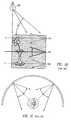
- FIG. 4Ashows a side view of a portion of a hologram display including tile 300 .
- Three co-planar rays of light emanating from light source 311are illustrated.
- the three rayseach have an associated angle of incidence 330 , 332 , and 334 with respect to the normal of hogels along the back edge 340 of tile 300 .
- the three rays illustratedlie in a plane that is perpendicular to the plane of the hogels along back edge 340 .
- the hogels of the present systemcan be created with both horizontal and vertical parallax, the image information varies across (by as much as 90° or more) the projection angles 344 in order to produce the parallax effect in the vertical.
- a computer graphic rendering system in printer control module 214(FIG. 2) is configured.
- the curved-format hologramis recorded in much the same way, and using the same equipment, as holograms that are to be mounted on flat substrates, as described in the '581 application.
- the computer model of the hogele.g., hogel image
- hogel imageis defined as an element whose orientation changes with respect to the image volume, depending on its eventual orientation in the display.
- the coordinates for the illumination source position for the final curved format displayis provided to the printer control module 214 to insure that the reference beam is properly redirected for each hogel to allow for distortionless image replay.
- the holographic recording materialis processed, and then applied to a curved substrate that conforms to the parameters that were specified for the image generation module 212 .
- the hologram for each tilecan be laminated to the substrate using adhesive films, attached to the substrate with vacuum suction, or other techniques capable of making the flexible film sheet firmly attach to the curved substrate.
- the hologramis then illuminated with a standard white light source from the position of reference illumination beam for tile that was specified for the image generation module 212 during recording. A distortion-free three-dimensional image with full parallax is produced.
- FIG. 4BA variety of curved formats can be implemented with the present invention.
- the curvescan be constant radius, or the hologram can include two or more radii of curvature that vary across the three dimensional space of the mounting substrate.
- FIG. 4BOne interesting format is shown in FIG. 4B as a top view of concave hemi-cylinder hologram 400 that produces an aerial image 402 centered in the cylinder 404 .
- the vieweradvantageously has complete access to the image volume within the field of view of hologram 400 . This allows the user to take measurements, and analyze the image from various viewpoints.
- each hogelindividually has a 110° angle of view in the horizontal direction. Note that, as illustrated in FIG. 4A, the vertical angle of view is typically 90°.
- the view angleis increase by virtue of the fact that the hogels have been wrapped around a point in space, i.e., the center of the cylinder.
- the reconstructed imageappears at the center of the cylinder, and as long as a viewer can see into the hemi-cylinder, they can see the image, yielding a 180° view angle in the horizontal direction.
- FIGS. 5A and 5BAnother interesting format is a fully cylindrical substrate 500 , as shown in FIGS. 5A and 5B, in which an aerial image 502 is also produced in the center. If the substrate 500 and the holographic recording material are substantially clear, the viewer can look through substrate 500 to view image 502 from 360°.
- a second cylindrical section 504 with a radius slightly larger than the hologram substrate 500can surround substrate 500 in order to provide a dark background to improve image contrast, if necessary.
- a polarizer oriented at 45°can be sandwiched between the hologram and the substrate. This would allow viewing through one side of the cylinder, i.e., light is allowed to pass through the polarizer from one side of the cylinder.
- the outside cylinder section 504can be rotatable by the viewer, so as to allow adjustment of its position as the viewer circles the hologram 506 .
- the full-parallax nature of the inventionthe fact that it is a reflection, and not a transmission hologram, and the wide vertical viewzone, enables the viewer to see the image even when their eye level is above or below the vertical extremes of the film. This is significant improvement over the alcove and multiplex holograms which display imagery that is visible only over a narrow vertical range.
- the cylindrical embodiment of the present inventionis a significant improvement over the reflection alcove for a number of other reasons as well.
- the full parallax nature of the present inventiongives more depth cues and the ability to look over and under the imaged object, while removing depth limiting and potentially distorting astigmatism.
- the current inventioncan produce full color imagery without the need for tedious and difficult emulsion swelling, and triple exposures.
- This systemis inherently scalable using tiling techniques disclosed in the '581 application in the same way that the flat format holograms produced with the same system are.
- the ability in the current recording system to redirect the reference beam for each hogelmakes is possible to tailor the illumination angle and distance independently of the print or substrate geometry.
- hologramscan be generated in accordance with the present invention for substrates having one or more radii of curvature. This is because the overall display can be divided into a number of tiles, and a radius of curvature is specified for each tile.
- the shape of the substratecan be geometric or irregular. Accordingly, various other embodiments and modifications and improvements not described herein may be within the spirit and scope of the present invention, as defined by the following claims.
Landscapes
- Physics & Mathematics (AREA)
- General Physics & Mathematics (AREA)
- Holo Graphy (AREA)
Abstract
Description
Claims (25)
Priority Applications (1)
| Application Number | Priority Date | Filing Date | Title |
|---|---|---|---|
| US09/908,828US6631016B1 (en) | 2001-07-18 | 2001-07-18 | Full-parallax holographic stereograms on curved substrates |
Applications Claiming Priority (1)
| Application Number | Priority Date | Filing Date | Title |
|---|---|---|---|
| US09/908,828US6631016B1 (en) | 2001-07-18 | 2001-07-18 | Full-parallax holographic stereograms on curved substrates |
Publications (1)
| Publication Number | Publication Date |
|---|---|
| US6631016B1true US6631016B1 (en) | 2003-10-07 |
Family
ID=28675869
Family Applications (1)
| Application Number | Title | Priority Date | Filing Date |
|---|---|---|---|
| US09/908,828Expired - LifetimeUS6631016B1 (en) | 2001-07-18 | 2001-07-18 | Full-parallax holographic stereograms on curved substrates |
Country Status (1)
| Country | Link |
|---|---|
| US (1) | US6631016B1 (en) |
Cited By (21)
| Publication number | Priority date | Publication date | Assignee | Title |
|---|---|---|---|---|
| US20030184831A1 (en)* | 2002-03-27 | 2003-10-02 | Rabbit Tanaka Corporation Limited | Integral hologram revolving lamp and method for making same |
| US20040001111A1 (en)* | 2002-06-28 | 2004-01-01 | Silicon Graphics, Inc. | Widgets displayed and operable on a surface of a volumetric display enclosure |
| US20050195157A1 (en)* | 2004-03-03 | 2005-09-08 | Gary Kramer | System for delivering and enabling interactivity with images |
| US20050195216A1 (en)* | 2004-03-03 | 2005-09-08 | Gary Kramer | System for delivering and enabling interactivity with images |
| US20050230641A1 (en)* | 2004-04-05 | 2005-10-20 | Won Chun | Data processing for three-dimensional displays |
| US20090229206A1 (en)* | 2008-03-11 | 2009-09-17 | Daniel Christman | Decorative holographic tile |
| US20100220098A1 (en)* | 2008-10-26 | 2010-09-02 | Zebra Imaging, Inc. | Converting 3D Data to Hogel Data |
| US20100238529A1 (en)* | 2009-03-23 | 2010-09-23 | Qualcomm Mems Technologies, Inc. | Dithered holographic frontlight |
| WO2012095703A1 (en) | 2011-01-14 | 2012-07-19 | Onural, Levent | An apparatus and methods for holographic display |
| US20130321740A1 (en)* | 2012-05-17 | 2013-12-05 | Samsung Display Co., Ltd. | Curved display apparatus and multi display apparatus having the same |
| US20150261186A1 (en)* | 2014-03-14 | 2015-09-17 | Electronics And Telecommunications Research Institute | Digital holographic image recording method and system based on hierarchical hogel |
| USD744579S1 (en)* | 2015-08-31 | 2015-12-01 | Nanolumens Acquisition, Inc. | Tunnel shaped display |
| US20160306204A1 (en)* | 2015-04-16 | 2016-10-20 | Samsung Display Co., Ltd. | Curved display device |
| US20180003975A1 (en)* | 2016-07-01 | 2018-01-04 | Intel Corporation | Holographic optical element design and manufacturing |
| US10258426B2 (en) | 2016-03-21 | 2019-04-16 | Washington University | System and method for virtual reality data integration and visualization for 3D imaging and instrument position data |
| EP3492960A1 (en)* | 2017-12-01 | 2019-06-05 | Rockwell Automation Technologies, Inc. | Arched collimating lens forming a disk-like illumination |
| US10573056B2 (en) | 2017-03-06 | 2020-02-25 | 3D Patents, Llc | Multi-view processing unit systems and methods |
| US10609266B2 (en) | 2018-08-21 | 2020-03-31 | Rockwell Automation Technologies, Inc. | Camera for wide field of view with an arbitrary aspect ratio |
| CN111624865A (en)* | 2020-06-04 | 2020-09-04 | 四川大学 | Cylindrical holographic occlusion removing method based on optical path restriction function |
| WO2022114342A1 (en)* | 2020-11-30 | 2022-06-02 | 주식회사 홀로랩 | Method and system for producing hologram for high-speed digital screen |
| US11650540B2 (en) | 2017-11-24 | 2023-05-16 | University Court Of The University Of St Andrews | Holographic device |
Citations (13)
| Publication number | Priority date | Publication date | Assignee | Title |
|---|---|---|---|---|
| US4364627A (en) | 1979-09-07 | 1982-12-21 | Eidetic Images, Inc. | Method and system for constructing a composite hologram |
| US4778262A (en) | 1986-10-14 | 1988-10-18 | American Bank Note Holographics, Inc. | Computer aided holography and holographic computer graphics |
| US4830445A (en)* | 1985-08-07 | 1989-05-16 | Robinson Anthony J | Holographic display apparatus |
| US4834476A (en) | 1987-03-31 | 1989-05-30 | Massachusetts Institute Of Technology | Real image holographic stereograms |
| US4969700A (en) | 1987-12-23 | 1990-11-13 | American Bank Note Holographics, Inc. | Computer aided holography and holographic computer graphics |
| US5044708A (en) | 1988-06-20 | 1991-09-03 | Thierry Garcon | Wide visual field hologram |
| US5138471A (en) | 1990-07-20 | 1992-08-11 | Mcgrew Stephen P | Holocomposer |
| US5216528A (en) | 1990-06-11 | 1993-06-01 | Fuji Photo Optical Co., Ltd. | Three-dimensional multiplex hologram |
| US5237433A (en) | 1992-01-03 | 1993-08-17 | Haines Kenneth A | Methods of hologram construction using computer-processed objects |
| GB2270772A (en)* | 1992-09-21 | 1994-03-23 | Charles Henry Dierks | Cylindrical white light transmission hologram image display |
| US5589957A (en) | 1994-03-15 | 1996-12-31 | Fujitsu Limited | Stereoscopic display apparatus using cylindrical screen |
| WO2000029909A1 (en)* | 1998-11-18 | 2000-05-25 | Zebra Imaging, Inc. | Method and apparatus for recording one-step, full-color, full-parallax, holographic stereograms |
| US6088140A (en)* | 1998-02-05 | 2000-07-11 | Zebra Imaging, Inc. | Segmented display system for large, continuous autostereoscopic images |
- 2001
- 2001-07-18USUS09/908,828patent/US6631016B1/ennot_activeExpired - Lifetime
Patent Citations (14)
| Publication number | Priority date | Publication date | Assignee | Title |
|---|---|---|---|---|
| US4364627A (en) | 1979-09-07 | 1982-12-21 | Eidetic Images, Inc. | Method and system for constructing a composite hologram |
| US4830445A (en)* | 1985-08-07 | 1989-05-16 | Robinson Anthony J | Holographic display apparatus |
| US4778262A (en) | 1986-10-14 | 1988-10-18 | American Bank Note Holographics, Inc. | Computer aided holography and holographic computer graphics |
| US4834476A (en) | 1987-03-31 | 1989-05-30 | Massachusetts Institute Of Technology | Real image holographic stereograms |
| US4969700A (en) | 1987-12-23 | 1990-11-13 | American Bank Note Holographics, Inc. | Computer aided holography and holographic computer graphics |
| US5044708A (en) | 1988-06-20 | 1991-09-03 | Thierry Garcon | Wide visual field hologram |
| US5216528A (en) | 1990-06-11 | 1993-06-01 | Fuji Photo Optical Co., Ltd. | Three-dimensional multiplex hologram |
| US5138471A (en) | 1990-07-20 | 1992-08-11 | Mcgrew Stephen P | Holocomposer |
| US5237433A (en) | 1992-01-03 | 1993-08-17 | Haines Kenneth A | Methods of hologram construction using computer-processed objects |
| GB2270772A (en)* | 1992-09-21 | 1994-03-23 | Charles Henry Dierks | Cylindrical white light transmission hologram image display |
| US5589957A (en) | 1994-03-15 | 1996-12-31 | Fujitsu Limited | Stereoscopic display apparatus using cylindrical screen |
| US6088140A (en)* | 1998-02-05 | 2000-07-11 | Zebra Imaging, Inc. | Segmented display system for large, continuous autostereoscopic images |
| US6268942B1 (en) | 1998-02-05 | 2001-07-31 | Zebra Imaging, Inc. | Segmented display system for large, continuous autostereoscopic images |
| WO2000029909A1 (en)* | 1998-11-18 | 2000-05-25 | Zebra Imaging, Inc. | Method and apparatus for recording one-step, full-color, full-parallax, holographic stereograms |
Non-Patent Citations (1)
| Title |
|---|
| Mark Holzbach, "Three-Dimensional Image Processing for Synthetic Holographic Stereograms," submitted to the Department of Architecture at the Massachusetts Institute of Technology, Sep., 1986, pp. 1-55. |
Cited By (44)
| Publication number | Priority date | Publication date | Assignee | Title |
|---|---|---|---|---|
| US6844948B2 (en)* | 2002-03-27 | 2005-01-18 | Rabbit Tanaka Corporation Limited | Integral hologram revolving lamp and method for making same |
| US20030184831A1 (en)* | 2002-03-27 | 2003-10-02 | Rabbit Tanaka Corporation Limited | Integral hologram revolving lamp and method for making same |
| US20040001111A1 (en)* | 2002-06-28 | 2004-01-01 | Silicon Graphics, Inc. | Widgets displayed and operable on a surface of a volumetric display enclosure |
| US7554541B2 (en)* | 2002-06-28 | 2009-06-30 | Autodesk, Inc. | Widgets displayed and operable on a surface of a volumetric display enclosure |
| US7956872B2 (en) | 2004-03-03 | 2011-06-07 | Virtual Iris Studios, Inc. | System for delivering and enabling interactivity with images |
| US20050195157A1 (en)* | 2004-03-03 | 2005-09-08 | Gary Kramer | System for delivering and enabling interactivity with images |
| US20050195216A1 (en)* | 2004-03-03 | 2005-09-08 | Gary Kramer | System for delivering and enabling interactivity with images |
| US7262783B2 (en) | 2004-03-03 | 2007-08-28 | Virtual Iris Studios, Inc. | System for delivering and enabling interactivity with images |
| US9087413B2 (en) | 2004-03-03 | 2015-07-21 | Engram Networking Llc | System for delivering and enabling interactivity with images |
| US7542050B2 (en) | 2004-03-03 | 2009-06-02 | Virtual Iris Studios, Inc. | System for delivering and enabling interactivity with images |
| US8411109B2 (en) | 2004-03-03 | 2013-04-02 | Engram Networking Llc | System for delivering and enabling interactivity with images |
| US7755643B2 (en) | 2004-03-03 | 2010-07-13 | Virtual Iris Studios, Inc. | System for delivering and enabling interactivity with images |
| US7525541B2 (en) | 2004-04-05 | 2009-04-28 | Actuality Systems, Inc. | Data processing for three-dimensional displays |
| US20050230641A1 (en)* | 2004-04-05 | 2005-10-20 | Won Chun | Data processing for three-dimensional displays |
| US20090229206A1 (en)* | 2008-03-11 | 2009-09-17 | Daniel Christman | Decorative holographic tile |
| US20100220098A1 (en)* | 2008-10-26 | 2010-09-02 | Zebra Imaging, Inc. | Converting 3D Data to Hogel Data |
| US8605081B2 (en)* | 2008-10-26 | 2013-12-10 | Zebra Imaging, Inc. | Converting 3D data to hogel data |
| US20100238529A1 (en)* | 2009-03-23 | 2010-09-23 | Qualcomm Mems Technologies, Inc. | Dithered holographic frontlight |
| WO2012095703A1 (en) | 2011-01-14 | 2012-07-19 | Onural, Levent | An apparatus and methods for holographic display |
| US9501036B2 (en) | 2011-01-14 | 2016-11-22 | Levent Onural | Apparatus and methods for holographic display |
| US20130321740A1 (en)* | 2012-05-17 | 2013-12-05 | Samsung Display Co., Ltd. | Curved display apparatus and multi display apparatus having the same |
| US9113553B2 (en)* | 2012-05-17 | 2015-08-18 | Samsung Electronics Co., Ltd. | Curved display apparatus and multi display apparatus having the same |
| US20150346542A1 (en)* | 2012-05-17 | 2015-12-03 | Samsung Display Co., Ltd. | Curved display apparatus and multi display apparatus having the same |
| US10031360B2 (en)* | 2012-05-17 | 2018-07-24 | Samsung Electronics Co., Ltd. | Curved display apparatus and multi display apparatus having the same |
| US9551893B2 (en)* | 2012-05-17 | 2017-01-24 | Samsung Electronics Co., Ltd. | Curved display apparatus and multi display apparatus having the same |
| US20170082889A1 (en)* | 2012-05-17 | 2017-03-23 | Samsung Electronics Co., Ltd. | Curved display apparatus and multi display apparatus having the same |
| US20150261186A1 (en)* | 2014-03-14 | 2015-09-17 | Electronics And Telecommunications Research Institute | Digital holographic image recording method and system based on hierarchical hogel |
| US20160306204A1 (en)* | 2015-04-16 | 2016-10-20 | Samsung Display Co., Ltd. | Curved display device |
| US10114244B2 (en)* | 2015-04-16 | 2018-10-30 | Samsung Display Co., Ltd. | Curved display device |
| USD744579S1 (en)* | 2015-08-31 | 2015-12-01 | Nanolumens Acquisition, Inc. | Tunnel shaped display |
| US10258426B2 (en) | 2016-03-21 | 2019-04-16 | Washington University | System and method for virtual reality data integration and visualization for 3D imaging and instrument position data |
| US11771520B2 (en) | 2016-03-21 | 2023-10-03 | Washington University | System and method for virtual reality data integration and visualization for 3D imaging and instrument position data |
| US20180003975A1 (en)* | 2016-07-01 | 2018-01-04 | Intel Corporation | Holographic optical element design and manufacturing |
| US10642043B2 (en)* | 2016-07-01 | 2020-05-05 | Intel Corporation | Holographic optical element design and manufacturing |
| US10937223B2 (en) | 2017-03-06 | 2021-03-02 | 3D Patents, Llc | Multi-view processing unit systems and methods |
| US10573056B2 (en) | 2017-03-06 | 2020-02-25 | 3D Patents, Llc | Multi-view processing unit systems and methods |
| US11423599B2 (en) | 2017-03-06 | 2022-08-23 | 3D Patents, Llc | Multi-view processing unit systems and methods |
| US11650540B2 (en) | 2017-11-24 | 2023-05-16 | University Court Of The University Of St Andrews | Holographic device |
| US10436953B2 (en) | 2017-12-01 | 2019-10-08 | Rockwell Automation Technologies Inc. | Arched collimating lens forming a disk-like illumination |
| EP3492960A1 (en)* | 2017-12-01 | 2019-06-05 | Rockwell Automation Technologies, Inc. | Arched collimating lens forming a disk-like illumination |
| US10609266B2 (en) | 2018-08-21 | 2020-03-31 | Rockwell Automation Technologies, Inc. | Camera for wide field of view with an arbitrary aspect ratio |
| CN111624865B (en)* | 2020-06-04 | 2021-11-02 | 四川大学 | Cylindrical holography de-occlusion method based on optical path limit function |
| CN111624865A (en)* | 2020-06-04 | 2020-09-04 | 四川大学 | Cylindrical holographic occlusion removing method based on optical path restriction function |
| WO2022114342A1 (en)* | 2020-11-30 | 2022-06-02 | 주식회사 홀로랩 | Method and system for producing hologram for high-speed digital screen |
Similar Documents
| Publication | Publication Date | Title |
|---|---|---|
| US6631016B1 (en) | Full-parallax holographic stereograms on curved substrates | |
| EP1131680B1 (en) | Apparatus and method for replicating a hologram using a steerable beam | |
| US5194971A (en) | Computer aided holography and holographic computer graphics | |
| EP0407497B1 (en) | Computer aided holography and holographic computer graphics | |
| US4778262A (en) | Computer aided holography and holographic computer graphics | |
| US4834476A (en) | Real image holographic stereograms | |
| US7190496B2 (en) | Enhanced environment visualization using holographic stereograms | |
| US5138471A (en) | Holocomposer | |
| US6665100B1 (en) | Autostereoscopic three dimensional display using holographic projection | |
| US20050122549A1 (en) | Computer assisted hologram forming method and apparatus | |
| JP3238755B2 (en) | Hologram creation and stereoscopic display method and stereoscopic display device | |
| Matsushima et al. | Simple wave-field rendering for photorealistic reconstruction in polygon-based high-definition computer holography | |
| JP2003516565A (en) | Holographic printer | |
| US20030184831A1 (en) | Integral hologram revolving lamp and method for making same | |
| US6323971B1 (en) | Hologram incorporating a plane with a projected image | |
| Bimber | Combining optical holograms with interactive computer graphics | |
| JP3338479B2 (en) | Hologram creation and stereoscopic display method and stereoscopic display device | |
| CN107253400A (en) | Digital hologram image printing machine and Method of printing | |
| US6822772B2 (en) | Holographic display | |
| Sánchez et al. | Design, development, and implementation of a low-cost full-parallax holoprinter | |
| Bimber et al. | Interacting with augmented holograms | |
| Benton | The reflection alcove hologram: a computer-graphic holographic stereogram | |
| Reichelt et al. | Principles of Display Holography | |
| JP3324328B2 (en) | Holographic three-dimensional hard copy creation method and creation apparatus | |
| JP2899496B2 (en) | Holographic three-dimensional hard copy and method and apparatus for producing the same |
Legal Events
| Date | Code | Title | Description |
|---|---|---|---|
| AS | Assignment | Owner name:ZEBRA IMAGING, INC., TEXAS Free format text:ASSIGNMENT OF ASSIGNORS INTEREST;ASSIGNORS:KLUG, MICHAEL A.;HOLZBACH, MARK E.;REEL/FRAME:012021/0251 Effective date:20010717 | |
| AS | Assignment | Owner name:SILICON VALLEY BANK, CALIFORNIA Free format text:SECURITY AGREEMENT;ASSIGNOR:ZEBRA IMAGING, INC.;REEL/FRAME:013343/0636 Effective date:20020910 | |
| STCF | Information on status: patent grant | Free format text:PATENTED CASE | |
| AS | Assignment | Owner name:SIERRA VENTURES VIII-A, L.P., AS COLLATERAL AGENT, Free format text:SECURITY AGREEMENT;ASSIGNOR:ZEBRA IMAGING, INC.;REEL/FRAME:016722/0276 Effective date:20051031 | |
| AS | Assignment | Owner name:VOYAGER CAPITAL FUND II-A, LP AS COLLATERAL AGENT, Free format text:ONE TRANSACTION: FIRST AMENDMENT TO INTELLECTUAL PROPERTY SECURITY AGREEMENT DATED OCTOBER 31, 2005; SUBORDINATION AGREEMENT; INTELLECTUAL PROPERTY SECURITY AGREEMENT;ASSIGNOR:ZEBRA IMAGING, INC.;REEL/FRAME:018039/0225 Effective date:20060731 Owner name:VOYAGER CAPITAL FUND II-A, LP AS COLLATERAL AGENT, Free format text:ONE TRANSACTION;ASSIGNOR:ZEBRA IMAGING, INC.;REEL/FRAME:018039/0225 Effective date:20060731 | |
| AS | Assignment | Owner name:ZEBRA IMAGING, INC., TEXAS Free format text:RELEASE BY SECURED PARTY;ASSIGNOR:VOYAGER CAPITAL FUND II-A, L.P., AS COLLATERAL AGENT FOR THE SECURED PARTIES IN THE SECURITY AGREEMENT;REEL/FRAME:018338/0205 Effective date:20060918 Owner name:ZEBRA IMAGING, INC., TEXAS Free format text:RELEASE BY SECURED PARTY;ASSIGNOR:VOYAGER CAPITAL FUND II-A, L.P., AS COLLATERAL AGENT FOR THE SECURED PARTIES LISTED IN THE SECURITY AGREEMENT;REEL/FRAME:018338/0142 Effective date:20060918 | |
| FEPP | Fee payment procedure | Free format text:PAT HOLDER CLAIMS SMALL ENTITY STATUS, ENTITY STATUS SET TO SMALL (ORIGINAL EVENT CODE: LTOS); ENTITY STATUS OF PATENT OWNER: SMALL ENTITY | |
| FPAY | Fee payment | Year of fee payment:4 | |
| AS | Assignment | Owner name:ZEBRA IMAGING INC.,TEXAS Free format text:RELEASE;ASSIGNOR:SILICON VALLEY BANK;REEL/FRAME:023892/0823 Effective date:20100203 | |
| FPAY | Fee payment | Year of fee payment:8 | |
| REMI | Maintenance fee reminder mailed | ||
| FPAY | Fee payment | Year of fee payment:12 | |
| SULP | Surcharge for late payment | Year of fee payment:11 | |
| AS | Assignment | Owner name:ZEBRA IMAGING, INC., TEXAS Free format text:RELEASE;ASSIGNOR:SILICON VALLEY BANK;REEL/FRAME:038830/0551 Effective date:20160510 | |
| AS | Assignment | Owner name:FOVI 3D, INC., TEXAS Free format text:ASSIGNMENT OF ASSIGNORS INTEREST;ASSIGNOR:ZEBRA IMAGING, INC.;REEL/FRAME:042391/0378 Effective date:20161020 | |
| AS | Assignment | Owner name:NUEVO CAPITAL PARTNERS, L.P., TEXAS Free format text:SECURITY INTEREST;ASSIGNOR:FOVI 3D, INC.;REEL/FRAME:048260/0043 Effective date:20190129 | |
| AS | Assignment | Owner name:3D PATENTS, LLC, KANSAS Free format text:ASSIGNMENT OF ASSIGNORS INTEREST;ASSIGNOR:FOVI3D, INC.;REEL/FRAME:050083/0745 Effective date:20190331 | |
| AS | Assignment | Owner name:HOLOTECH SWITZERLAND AG, SWITZERLAND Free format text:ASSIGNMENT OF ASSIGNORS INTEREST;ASSIGNOR:3D PATENTS, LLC;REEL/FRAME:052060/0114 Effective date:20200214 |