US6629972B2 - Cryosurgical catheter - Google Patents
Cryosurgical catheterDownload PDFInfo
- Publication number
- US6629972B2 US6629972B2US09/845,535US84553501AUS6629972B2US 6629972 B2US6629972 B2US 6629972B2US 84553501 AUS84553501 AUS 84553501AUS 6629972 B2US6629972 B2US 6629972B2
- Authority
- US
- United States
- Prior art keywords
- thermally
- transmissive
- flexible member
- cooling structure
- elements
- Prior art date
- Legal status (The legal status is an assumption and is not a legal conclusion. Google has not performed a legal analysis and makes no representation as to the accuracy of the status listed.)
- Expired - Lifetime, expires
Links
Images


Classifications
- A—HUMAN NECESSITIES
- A61—MEDICAL OR VETERINARY SCIENCE; HYGIENE
- A61M—DEVICES FOR INTRODUCING MEDIA INTO, OR ONTO, THE BODY; DEVICES FOR TRANSDUCING BODY MEDIA OR FOR TAKING MEDIA FROM THE BODY; DEVICES FOR PRODUCING OR ENDING SLEEP OR STUPOR
- A61M25/00—Catheters; Hollow probes
- A61M25/0021—Catheters; Hollow probes characterised by the form of the tubing
- A61M25/0023—Catheters; Hollow probes characterised by the form of the tubing by the form of the lumen, e.g. cross-section, variable diameter
- A61M25/0026—Multi-lumen catheters with stationary elements
- A61M25/0029—Multi-lumen catheters with stationary elements characterized by features relating to least one lumen located at the middle part of the catheter, e.g. slots, flaps, valves, cuffs, apertures, notches, grooves or rapid exchange ports
- A—HUMAN NECESSITIES
- A61—MEDICAL OR VETERINARY SCIENCE; HYGIENE
- A61B—DIAGNOSIS; SURGERY; IDENTIFICATION
- A61B18/00—Surgical instruments, devices or methods for transferring non-mechanical forms of energy to or from the body
- A61B18/02—Surgical instruments, devices or methods for transferring non-mechanical forms of energy to or from the body by cooling, e.g. cryogenic techniques
- A—HUMAN NECESSITIES
- A61—MEDICAL OR VETERINARY SCIENCE; HYGIENE
- A61B—DIAGNOSIS; SURGERY; IDENTIFICATION
- A61B17/00—Surgical instruments, devices or methods
- A61B17/00234—Surgical instruments, devices or methods for minimally invasive surgery
- A61B2017/00238—Type of minimally invasive operation
- A61B2017/00243—Type of minimally invasive operation cardiac
- A—HUMAN NECESSITIES
- A61—MEDICAL OR VETERINARY SCIENCE; HYGIENE
- A61B—DIAGNOSIS; SURGERY; IDENTIFICATION
- A61B17/00—Surgical instruments, devices or methods
- A61B17/00234—Surgical instruments, devices or methods for minimally invasive surgery
- A61B2017/00292—Surgical instruments, devices or methods for minimally invasive surgery mounted on or guided by flexible, e.g. catheter-like, means
- A—HUMAN NECESSITIES
- A61—MEDICAL OR VETERINARY SCIENCE; HYGIENE
- A61B—DIAGNOSIS; SURGERY; IDENTIFICATION
- A61B17/00—Surgical instruments, devices or methods
- A61B2017/00973—Surgical instruments, devices or methods pedal-operated
- A—HUMAN NECESSITIES
- A61—MEDICAL OR VETERINARY SCIENCE; HYGIENE
- A61B—DIAGNOSIS; SURGERY; IDENTIFICATION
- A61B17/00—Surgical instruments, devices or methods
- A61B17/22—Implements for squeezing-off ulcers or the like on inner organs of the body; Implements for scraping-out cavities of body organs, e.g. bones; for invasive removal or destruction of calculus using mechanical vibrations; for removing obstructions in blood vessels, not otherwise provided for
- A61B2017/22051—Implements for squeezing-off ulcers or the like on inner organs of the body; Implements for scraping-out cavities of body organs, e.g. bones; for invasive removal or destruction of calculus using mechanical vibrations; for removing obstructions in blood vessels, not otherwise provided for with an inflatable part, e.g. balloon, for positioning, blocking, or immobilisation
- A—HUMAN NECESSITIES
- A61—MEDICAL OR VETERINARY SCIENCE; HYGIENE
- A61B—DIAGNOSIS; SURGERY; IDENTIFICATION
- A61B18/00—Surgical instruments, devices or methods for transferring non-mechanical forms of energy to or from the body
- A61B2018/00053—Mechanical features of the instrument of device
- A61B2018/00059—Material properties
- A61B2018/00089—Thermal conductivity
- A61B2018/00095—Thermal conductivity high, i.e. heat conducting
- A—HUMAN NECESSITIES
- A61—MEDICAL OR VETERINARY SCIENCE; HYGIENE
- A61B—DIAGNOSIS; SURGERY; IDENTIFICATION
- A61B18/00—Surgical instruments, devices or methods for transferring non-mechanical forms of energy to or from the body
- A61B18/02—Surgical instruments, devices or methods for transferring non-mechanical forms of energy to or from the body by cooling, e.g. cryogenic techniques
- A61B2018/0212—Surgical instruments, devices or methods for transferring non-mechanical forms of energy to or from the body by cooling, e.g. cryogenic techniques using an instrument inserted into a body lumen, e.g. catheter
- A—HUMAN NECESSITIES
- A61—MEDICAL OR VETERINARY SCIENCE; HYGIENE
- A61B—DIAGNOSIS; SURGERY; IDENTIFICATION
- A61B18/00—Surgical instruments, devices or methods for transferring non-mechanical forms of energy to or from the body
- A61B18/02—Surgical instruments, devices or methods for transferring non-mechanical forms of energy to or from the body by cooling, e.g. cryogenic techniques
- A61B2018/0231—Characteristics of handpieces or probes
- A61B2018/0262—Characteristics of handpieces or probes using a circulating cryogenic fluid
- A—HUMAN NECESSITIES
- A61—MEDICAL OR VETERINARY SCIENCE; HYGIENE
- A61B—DIAGNOSIS; SURGERY; IDENTIFICATION
- A61B5/00—Measuring for diagnostic purposes; Identification of persons
- A61B5/24—Detecting, measuring or recording bioelectric or biomagnetic signals of the body or parts thereof
- A61B5/25—Bioelectric electrodes therefor
- A61B5/279—Bioelectric electrodes therefor specially adapted for particular uses
- A61B5/28—Bioelectric electrodes therefor specially adapted for particular uses for electrocardiography [ECG]
- A61B5/283—Invasive
- A—HUMAN NECESSITIES
- A61—MEDICAL OR VETERINARY SCIENCE; HYGIENE
- A61F—FILTERS IMPLANTABLE INTO BLOOD VESSELS; PROSTHESES; DEVICES PROVIDING PATENCY TO, OR PREVENTING COLLAPSING OF, TUBULAR STRUCTURES OF THE BODY, e.g. STENTS; ORTHOPAEDIC, NURSING OR CONTRACEPTIVE DEVICES; FOMENTATION; TREATMENT OR PROTECTION OF EYES OR EARS; BANDAGES, DRESSINGS OR ABSORBENT PADS; FIRST-AID KITS
- A61F7/00—Heating or cooling appliances for medical or therapeutic treatment of the human body
- A61F7/02—Compresses or poultices for effecting heating or cooling
- A61F2007/0295—Compresses or poultices for effecting heating or cooling for heating or cooling or use at more than one temperature
- A61F2007/0298—Compresses or poultices for effecting heating or cooling for heating or cooling or use at more than one temperature with a section for heating and a section for cooling
- A—HUMAN NECESSITIES
- A61—MEDICAL OR VETERINARY SCIENCE; HYGIENE
- A61M—DEVICES FOR INTRODUCING MEDIA INTO, OR ONTO, THE BODY; DEVICES FOR TRANSDUCING BODY MEDIA OR FOR TAKING MEDIA FROM THE BODY; DEVICES FOR PRODUCING OR ENDING SLEEP OR STUPOR
- A61M25/00—Catheters; Hollow probes
- A61M25/0021—Catheters; Hollow probes characterised by the form of the tubing
- A61M25/0023—Catheters; Hollow probes characterised by the form of the tubing by the form of the lumen, e.g. cross-section, variable diameter
- A61M25/0026—Multi-lumen catheters with stationary elements
- A61M2025/0039—Multi-lumen catheters with stationary elements characterized by lumina being arranged coaxially
- Y—GENERAL TAGGING OF NEW TECHNOLOGICAL DEVELOPMENTS; GENERAL TAGGING OF CROSS-SECTIONAL TECHNOLOGIES SPANNING OVER SEVERAL SECTIONS OF THE IPC; TECHNICAL SUBJECTS COVERED BY FORMER USPC CROSS-REFERENCE ART COLLECTIONS [XRACs] AND DIGESTS
- Y10—TECHNICAL SUBJECTS COVERED BY FORMER USPC
- Y10S—TECHNICAL SUBJECTS COVERED BY FORMER USPC CROSS-REFERENCE ART COLLECTIONS [XRACs] AND DIGESTS
- Y10S977/00—Nanotechnology
- Y10S977/902—Specified use of nanostructure
- Y10S977/904—Specified use of nanostructure for medical, immunological, body treatment, or diagnosis
- Y10S977/906—Drug delivery
Definitions
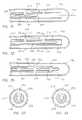
- FIG. 13is a sectional view of the catheter of FIG. 3 taken along line 13 — 13 ;
- FIG. 18depicts yet another embodiment of a catheter in accordance with the invention.
- FIG. 25illustrates yet another embodiment of the catheter
- One or more temperature sensors 20 in electrical communication with the controller 16can be provided to regulate or terminate the flow of cryogenic fluid into the catheter 14 when a predetermined temperature at a selected point or points on or within the catheter is/are obtained.
- a temperature sensorcan be placed at a point proximate the distal end 22 of the catheter and other temperature sensors 20 can be placed at spaced intervals between the distal end of the catheter and another point that is between the distal end and the proximal end.
- the catheter 14includes a flexible member 24 having a thermally-transmissive region 26 and a fluid path through the flexible member to the thermally-transmissive region.
- a fluid pathis also provided from the thermally-transmissive region to a point external to the catheter, such as the proximal end 12 .
- exemplary fluid pathscan be one or more channels defined by the flexible member 24 , and/or by one or more additional flexible members that are internal to the first flexible member 24 .
- a “thermally-transmissive region”is intended to broadly encompass any structure or region of the catheter 14 that readily conducts heat.
- thermally-transmissive region 26a metal structure exposed (directly or indirectly) to the cryogenic fluid path is considered a thermally-transmissive region 26 even if an adjacent polymeric or latex catheter portion also permits heat transfer, but to a much lesser extent than the metal.
- the thermally-transmissive region 26can be viewed as a relative term to compare the heat transfer characteristics of different catheter regions or structures.
- the coil 52is solid. However, in other embodiments the coil can be an elongate, hollow, gas expansion chamber.
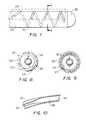
- FIG. 10illustrates a portion of a helical coil 52 that includes a passage that defines at least a portion of a fluid path through a flexible member of the catheter.
- the coil 52defines a first fluid path diameter at a fluid entry point 66 and a second fluid path diameter that is greater than the first fluid path diameter at a gas expansion or boiling location 68 .
- Gas escaping from a fluid exit point 70can be exhausted through an open central region of the coil and/or another passage through the flexible member 24 .
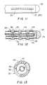
- an embodiment of the catheteris illustrated having three flexible members or injection tubes 210 , 211 and 212 disposed within a first or outer flexible member 200 .
- the inner flexible members 210 , 211 and 212are arranged in a staggered configuration within the outer flexible member 200 .
- staggeredmay be used to designate both a linearly/axially staggered configuration or alternatively, a rotationally staggered configuration.
- the flexible members 210 , 211 and 212thus define multiple staggered fluid paths within the outer member 200 .
Landscapes
- Health & Medical Sciences (AREA)
- Life Sciences & Earth Sciences (AREA)
- Surgery (AREA)
- Public Health (AREA)
- Nuclear Medicine, Radiotherapy & Molecular Imaging (AREA)
- Engineering & Computer Science (AREA)
- Biomedical Technology (AREA)
- Heart & Thoracic Surgery (AREA)
- Veterinary Medicine (AREA)
- Animal Behavior & Ethology (AREA)
- General Health & Medical Sciences (AREA)
- Anesthesiology (AREA)
- Hematology (AREA)
- Pulmonology (AREA)
- Biophysics (AREA)
- Otolaryngology (AREA)
- Medical Informatics (AREA)
- Molecular Biology (AREA)
- Surgical Instruments (AREA)
- Thermotherapy And Cooling Therapy Devices (AREA)
- Media Introduction/Drainage Providing Device (AREA)
Abstract
Description
Claims (36)
Priority Applications (8)
| Application Number | Priority Date | Filing Date | Title |
|---|---|---|---|
| US09/845,535US6629972B2 (en) | 1997-02-27 | 2001-04-30 | Cryosurgical catheter |
| US10/050,452US6669689B2 (en) | 1997-02-27 | 2002-01-16 | Cryosurgical catheter |
| US10/346,032US6913604B2 (en) | 1997-02-27 | 2003-01-16 | Cryosurgical catheter |
| US10/657,922US6942659B2 (en) | 1997-02-27 | 2003-09-09 | Cryosurgical catheter |
| US11/224,370US7753905B2 (en) | 1997-02-27 | 2005-09-12 | Cryosurgical catheter |
| US12/791,985US7914526B2 (en) | 1997-02-27 | 2010-06-02 | Cryosurgical catheter |
| US12/792,376US8043284B2 (en) | 1997-02-27 | 2010-06-02 | Cryosurgical catheter |
| US13/238,607US8585690B2 (en) | 1997-02-27 | 2011-09-21 | Cryosurgical catheter |
Applications Claiming Priority (5)
| Application Number | Priority Date | Filing Date | Title |
|---|---|---|---|
| US08/807,382US5899898A (en) | 1997-02-27 | 1997-02-27 | Cryosurgical linear ablation |
| US08/893,825US5899899A (en) | 1997-02-27 | 1997-07-11 | Cryosurgical linear ablation structure |
| US09/201,071US6235019B1 (en) | 1997-02-27 | 1998-11-30 | Cryosurgical catheter |
| US09/845,535US6629972B2 (en) | 1997-02-27 | 2001-04-30 | Cryosurgical catheter |
| US09/850,668US6540740B2 (en) | 1997-02-27 | 2001-05-07 | Cryosurgical catheter |
Related Parent Applications (1)
| Application Number | Title | Priority Date | Filing Date |
|---|---|---|---|
| US09/201,071ContinuationUS6235019B1 (en) | 1997-02-27 | 1998-11-30 | Cryosurgical catheter |
Related Child Applications (3)
| Application Number | Title | Priority Date | Filing Date |
|---|---|---|---|
| US10/050,452ContinuationUS6669689B2 (en) | 1997-02-27 | 2002-01-16 | Cryosurgical catheter |
| US10/346,032ContinuationUS6913604B2 (en) | 1997-02-27 | 2003-01-16 | Cryosurgical catheter |
| US10/657,922ContinuationUS6942659B2 (en) | 1997-02-27 | 2003-09-09 | Cryosurgical catheter |
Publications (2)
| Publication Number | Publication Date |
|---|---|
| US20020077624A1 US20020077624A1 (en) | 2002-06-20 |
| US6629972B2true US6629972B2 (en) | 2003-10-07 |
Family
ID=27394240
Family Applications (2)
| Application Number | Title | Priority Date | Filing Date |
|---|---|---|---|
| US09/201,071Expired - LifetimeUS6235019B1 (en) | 1997-02-27 | 1998-11-30 | Cryosurgical catheter |
| US09/845,535Expired - LifetimeUS6629972B2 (en) | 1997-02-27 | 2001-04-30 | Cryosurgical catheter |
Family Applications Before (1)
| Application Number | Title | Priority Date | Filing Date |
|---|---|---|---|
| US09/201,071Expired - LifetimeUS6235019B1 (en) | 1997-02-27 | 1998-11-30 | Cryosurgical catheter |
Country Status (1)
| Country | Link |
|---|---|
| US (2) | US6235019B1 (en) |
Cited By (25)
| Publication number | Priority date | Publication date | Assignee | Title |
|---|---|---|---|---|
| US20030220634A1 (en)* | 2000-08-09 | 2003-11-27 | Ryba Eric L. | Refrigeration source for a cryoablation catheter |
| US20040024413A1 (en)* | 2002-07-31 | 2004-02-05 | Lentz David J. | Wire reinforced articulation segment |
| US20040034345A1 (en)* | 2002-08-16 | 2004-02-19 | Lentz David J. | Heat transfer segment for a cryoablation catheter |
| US20040034365A1 (en)* | 2002-08-16 | 2004-02-19 | Lentz David J. | Catheter having articulation system |
| US20040034344A1 (en)* | 2002-08-16 | 2004-02-19 | Eric Ryba | Tip pressure monitoring for cryoablation catheters |
| US20040116916A1 (en)* | 2002-12-11 | 2004-06-17 | Lentz David J. | Coaxial catheter system for performing a single step cryoablation |
| US20040116921A1 (en)* | 2002-12-11 | 2004-06-17 | Marshall Sherman | Cold tip rf/ultrasonic ablation catheter |
| US20040116917A1 (en)* | 2002-12-11 | 2004-06-17 | Lentz David J. | System and method for performing a single step cryoablation |
| US6824543B2 (en) | 2002-12-11 | 2004-11-30 | Cryocor, Inc. | Guidance system for a cryocatheter |
| US20040243118A1 (en)* | 2001-06-01 | 2004-12-02 | Ayers Gregory M. | Device and method for positioning a catheter tip for creating a cryogenic lesion |
| US20050016188A1 (en)* | 2003-07-24 | 2005-01-27 | Lentz David J. | Distal end for cryoablation catheters |
| US20050177146A1 (en)* | 2004-02-10 | 2005-08-11 | Marshall Sherman | System and method for assessing ice ball formation during a cryoablation procedure |
| US20050198972A1 (en)* | 2004-03-10 | 2005-09-15 | Lentz David J. | Pressure-temperature control for a cryoablation catheter system |
| US20050283146A1 (en)* | 2004-06-17 | 2005-12-22 | Lentz David J | Thermally extended spiral cryotip for a cryoablation catheter |
| US7195625B2 (en) | 2002-12-11 | 2007-03-27 | Cryocor, Inc. | Catheter system for performing a single step cryoablation |
| US20080306475A1 (en)* | 2007-06-08 | 2008-12-11 | Lentz David J | Cryo-applicator cross-section configuration |
| US20090209949A1 (en)* | 2008-02-19 | 2009-08-20 | Boston Scientific Scimed, Inc. | Apparatus and methods for uniformly distributing coolant within a cryo-ablation device |
| WO2009112269A2 (en) | 2008-03-12 | 2009-09-17 | Afreeze Gmbh | Ablation system |
| US20090281533A1 (en)* | 2008-05-12 | 2009-11-12 | Boston Scientific Scimed, Inc. | Apparatus and method for chilling cryo-ablation coolant and resulting cryo-ablation system |
| US20090287202A1 (en)* | 2008-05-15 | 2009-11-19 | Boston Scientific Scimed, Inc. | Apparatus and methods for cryogenically ablating tissue and adjusting cryogenic ablation regions |
| US20100049184A1 (en)* | 2008-08-22 | 2010-02-25 | Boston Scientific Scimed, Inc. | Regulating Pressure to Lower Temperature in a Cryotherapy Balloon Catheter |
| US20110313410A1 (en)* | 2010-06-16 | 2011-12-22 | Werneth Randell L | Cryogenic medical device with thermal guard and method |
| US20120010605A1 (en)* | 1997-02-27 | 2012-01-12 | Medtronic Cryocath Lp | Cryosurgical catheter |
| US8133199B2 (en) | 2008-08-27 | 2012-03-13 | Boston Scientific Scimed, Inc. | Electroactive polymer activation system for a medical device |
| US8915908B2 (en) | 2009-03-20 | 2014-12-23 | Atricure, Inc. | Cryogenic probe |
Families Citing this family (67)
| Publication number | Priority date | Publication date | Assignee | Title |
|---|---|---|---|---|
| US6602247B2 (en)* | 1997-02-27 | 2003-08-05 | Cryocath Technologies Inc. | Apparatus and method for performing a treatment on a selected tissue region |
| US6913604B2 (en)* | 1997-02-27 | 2005-07-05 | Cryocath Technologies Inc. | Cryosurgical catheter |
| US5971979A (en)* | 1997-12-02 | 1999-10-26 | Odyssey Technologies, Inc. | Method for cryogenic inhibition of hyperplasia |
| US7458984B2 (en)* | 1998-01-23 | 2008-12-02 | Innercool Therapies, Inc. | System and method for inducing hypothermia with active patient temperature control employing catheter-mounted temperature sensor and temperature projection algorithm |
| US6312452B1 (en) | 1998-01-23 | 2001-11-06 | Innercool Therapies, Inc. | Selective organ cooling catheter with guidewire apparatus and temperature-monitoring device |
| US6685732B2 (en) | 1998-03-31 | 2004-02-03 | Innercool Therapies, Inc. | Method and device for performing cooling- or cryo-therapies for, e.g., angioplasty with reduced restenosis or pulmonary vein cell necrosis to inhibit atrial fibrillation employing microporous balloon |
| US6602276B2 (en) | 1998-03-31 | 2003-08-05 | Innercool Therapies, Inc. | Method and device for performing cooling- or cryo-therapies for, e.g., angioplasty with reduced restenosis or pulmonary vein cell necrosis to inhibit atrial fibrillation |
| US6905494B2 (en) | 1998-03-31 | 2005-06-14 | Innercool Therapies, Inc. | Method and device for performing cooling- or cryo-therapies for, e.g., angioplasty with reduced restenosis or pulmonary vein cell necrosis to inhibit atrial fibrillation employing tissue protection |
| US7001378B2 (en) | 1998-03-31 | 2006-02-21 | Innercool Therapies, Inc. | Method and device for performing cooling or cryo-therapies, for, e.g., angioplasty with reduced restenosis or pulmonary vein cell necrosis to inhibit atrial fibrillation employing tissue protection |
| US7291144B2 (en)* | 1998-03-31 | 2007-11-06 | Innercool Therapies, Inc. | Method and device for performing cooling- or cryo-therapies for, e.g., angioplasty with reduced restenosis or pulmonary vein cell necrosis to inhibit atrial fibrillation |
| US20050228367A1 (en)* | 1999-01-25 | 2005-10-13 | Marwan Abboud | Leak detection system for catheter based medical device |
| US6432102B2 (en)* | 1999-03-15 | 2002-08-13 | Cryovascular Systems, Inc. | Cryosurgical fluid supply |
| US6514245B1 (en)* | 1999-03-15 | 2003-02-04 | Cryovascular Systems, Inc. | Safety cryotherapy catheter |
| AT409584B (en)* | 2000-02-23 | 2002-09-25 | Nikolai Dr Korpan | CONNECTION ARRANGEMENT BETWEEN THE COAXIAL LINES FOR DIRECT AND BACKFLOW OF THE CRYOGENIC MEDIUM |
| US6471694B1 (en) | 2000-08-09 | 2002-10-29 | Cryogen, Inc. | Control system for cryosurgery |
| US7097641B1 (en)* | 1999-12-09 | 2006-08-29 | Cryocath Technologies Inc. | Catheter with cryogenic and heating ablation |
| US20040220559A1 (en)* | 2000-03-01 | 2004-11-04 | Kramer Hans W. | Preparation of working fluid for use in cryotherapies |
| US6551309B1 (en)* | 2000-09-14 | 2003-04-22 | Cryoflex, Inc. | Dual action cryoprobe and methods of using the same |
| US6673066B2 (en)* | 2000-11-10 | 2004-01-06 | Cardiostream, Inc. | Apparatus and method to diagnose and treat vulnerable plaque |
| US6761715B2 (en)* | 2001-04-26 | 2004-07-13 | Ronald J. Carroll | Method and device for neurocryo analgesia and anesthesia |
| US6767346B2 (en) | 2001-09-20 | 2004-07-27 | Endocare, Inc. | Cryosurgical probe with bellows shaft |
| US6579287B2 (en) | 2001-10-09 | 2003-06-17 | Cryocath Technologies Inc. | Cryosurgical ablation device having sequential injection and method therefor |
| WO2003033050A1 (en) | 2001-10-12 | 2003-04-24 | Applied Medical Resources Corporation | High-flow low-pressure irrigation system |
| AU2002359814A1 (en)* | 2001-12-19 | 2003-07-09 | Ran Yaron | Miniature refrigeration system for cryothermal ablation catheter |
| US20040024392A1 (en)* | 2002-08-05 | 2004-02-05 | Lewis James D. | Apparatus and method for cryosurgery |
| DE10332564A1 (en)* | 2003-07-11 | 2005-01-27 | Celon Ag Medical Instruments | Surgical device for coagulation or ablation of tissue, comprising hollow shaft accommodating cooling duct and two ring-shaped electrodes |
| US20050027289A1 (en)* | 2003-07-31 | 2005-02-03 | Thomas Castellano | Cryoablation systems and methods |
| US8491636B2 (en)* | 2004-03-23 | 2013-07-23 | Medtronic Cryopath LP | Method and apparatus for inflating and deflating balloon catheters |
| US9555223B2 (en) | 2004-03-23 | 2017-01-31 | Medtronic Cryocath Lp | Method and apparatus for inflating and deflating balloon catheters |
| US7727228B2 (en) | 2004-03-23 | 2010-06-01 | Medtronic Cryocath Lp | Method and apparatus for inflating and deflating balloon catheters |
| US7156840B2 (en)* | 2004-06-29 | 2007-01-02 | Cryocor, Inc. | Pressure monitor for cryoablation catheter |
| US7357797B2 (en)* | 2004-06-30 | 2008-04-15 | Cryocor, Inc. | System and method for varying return pressure to control tip temperature of a cryoablation catheter |
| US7163535B2 (en)* | 2004-06-30 | 2007-01-16 | Cryocor, Inc. | System for detecting leaks and occlusions in a cryoablation catheter |
| US20060069385A1 (en)* | 2004-09-28 | 2006-03-30 | Scimed Life Systems, Inc. | Methods and apparatus for tissue cryotherapy |
| US7635383B2 (en)* | 2004-09-28 | 2009-12-22 | Boston Scientific Scimed, Inc. | Rotating stent delivery system for side branch access and protection and method of using same |
| US8206345B2 (en)* | 2005-03-07 | 2012-06-26 | Medtronic Cryocath Lp | Fluid control system for a medical device |
| US8992515B2 (en)* | 2005-05-13 | 2015-03-31 | Medtronic Cryocath Lp | Coolant injection tube |
| US20060270981A1 (en)* | 2005-05-13 | 2006-11-30 | Leonilda Capuano | Coiled injection tube |
| US8726909B2 (en) | 2006-01-27 | 2014-05-20 | Usgi Medical, Inc. | Methods and apparatus for revision of obesity procedures |
| US20080097251A1 (en)* | 2006-06-15 | 2008-04-24 | Eilaz Babaev | Method and apparatus for treating vascular obstructions |
| US20070299433A1 (en)* | 2006-06-27 | 2007-12-27 | C2 Therapeutics | Barrett's Esophagus Cryogenic Ablation System |
| US8162929B2 (en)* | 2007-06-01 | 2012-04-24 | Boston Scientific Scimed, Inc. | Cryoablation segment for creating linear lesions |
| US20080312644A1 (en)* | 2007-06-14 | 2008-12-18 | Boston Scientific Scimed, Inc. | Cryogenic balloon ablation instruments and systems |
| WO2010083281A1 (en)* | 2009-01-15 | 2010-07-22 | Boston Scientific Scimed, Inc. | Controlling depth of cryoablation |
| US20100241113A1 (en)* | 2009-03-20 | 2010-09-23 | Boston Scientific Scimed, Inc. | Protecting the phrenic nerve while ablating cardiac tissue |
| WO2010111122A1 (en)* | 2009-03-23 | 2010-09-30 | Boston Scientific Scimed, Inc. | Systems apparatus for distributing coolant within a cryo-ablation device |
| US20110184402A1 (en)* | 2009-11-02 | 2011-07-28 | Cpsi Biotech | Flexible Cryogenic Probe Tip |
| US8986293B2 (en)* | 2010-01-27 | 2015-03-24 | Medtronic Cryocath Lp | Cryoballoon refrigerant dispersion control |
| US9445859B2 (en) | 2010-01-29 | 2016-09-20 | Medtronic Cryocath Lp | Multifunctional ablation device |
| US9017319B2 (en)* | 2011-01-05 | 2015-04-28 | Covidien Lp | Energy-delivery devices with flexible fluid-cooled shaft, inflow/outflow junctions suitable for use with same, and systems including same |
| EP2670328B1 (en) | 2011-02-01 | 2019-10-16 | Channel Medsystems, Inc. | Apparatus for cyrogenic treatment of a body cavity or lumen |
| US9039689B2 (en) | 2011-05-11 | 2015-05-26 | Icecure Medical Ltd. | Phase separation of cryogen in cryosurgical instrument |
| CN103442657B (en)* | 2011-05-11 | 2016-05-25 | 艾斯酷瑞医药有限公司 | For the coil exchanger of Cryobiopsy probe |
| US9314588B2 (en) | 2011-10-28 | 2016-04-19 | Medtronic Cryocath Lp | Systems and methods for variable injection flow |
| US10076384B2 (en) | 2013-03-08 | 2018-09-18 | Symple Surgical, Inc. | Balloon catheter apparatus with microwave emitter |
| FR3006594A1 (en)* | 2013-06-11 | 2014-12-12 | Sorin Crm Sas | IMPLANTABLE MICROSONDE FOR DETECTION / STIMULATION INCORPORATING AN ANTI-INFLAMMATORY AGENT |
| US10610279B2 (en) | 2014-04-10 | 2020-04-07 | Channel Medsystems, Inc. | Apparatus and methods for regulating cryogenic treatment |
| US10058371B2 (en)* | 2015-11-18 | 2018-08-28 | Medtronic Cryocath Lp | Multi-lobe balloon for cryoablation |
| US11871977B2 (en) | 2016-05-19 | 2024-01-16 | Csa Medical, Inc. | Catheter extension control |
| WO2018026985A1 (en)* | 2016-08-04 | 2018-02-08 | Csa Medical, Inc. | Rotational cryogen delivery device |
| EP4186450B1 (en) | 2016-12-09 | 2025-01-22 | St. Jude Medical, Cardiology Division, Inc. | Pulmonary vein isolation balloon catheter |
| US10492844B2 (en) | 2017-05-25 | 2019-12-03 | Channel Medsystems, Inc. | Tethered system for cryogenic treatment |
| US12144532B2 (en) | 2017-10-27 | 2024-11-19 | St. Jude Medical, Cardiology Division, Inc. | Apparatus and system for cryo-therapy balloon |
| US20200345403A1 (en)* | 2019-05-03 | 2020-11-05 | The Board Of Trustees Of The Leland Stanford Junior University | Instruments and methodology involving cryoablation |
| US11633224B2 (en) | 2020-02-10 | 2023-04-25 | Icecure Medical Ltd. | Cryogen pump |
| US12426934B2 (en) | 2022-02-28 | 2025-09-30 | Icecure Medical Ltd. | Cryogen flow control |
| US12215811B2 (en) | 2022-07-18 | 2025-02-04 | Icecure Medical Ltd. | Cryogenic system connector |
Citations (43)
| Publication number | Priority date | Publication date | Assignee | Title |
|---|---|---|---|---|
| USRE28657E (en)* | 1972-05-08 | 1975-12-23 | Cryosurgical apparatus | |
| US4375220A (en) | 1980-05-09 | 1983-03-01 | Matvias Fredrick M | Microwave applicator with cooling mechanism for intracavitary treatment of cancer |
| US4660571A (en) | 1985-07-18 | 1987-04-28 | Cordis Corporation | Percutaneous lead having radially adjustable electrode |
| US4664120A (en) | 1986-01-22 | 1987-05-12 | Cordis Corporation | Adjustable isodiametric atrial-ventricular pervenous lead |
| US4690155A (en) | 1985-07-03 | 1987-09-01 | Cordis Corporation | Monophasic action potential recording lead |
| US4699147A (en) | 1985-09-25 | 1987-10-13 | Cordis Corporation | Intraventricular multielectrode cardial mapping probe and method for using same |
| US4709698A (en) | 1986-05-14 | 1987-12-01 | Thomas J. Fogarty | Heatable dilation catheter |
| US4754752A (en) | 1986-07-28 | 1988-07-05 | Robert Ginsburg | Vascular catheter |
| US4776349A (en) | 1985-10-04 | 1988-10-11 | Basem Nashef | Tubular device for the treatment of hollow organs with electric current |
| US4945912A (en) | 1988-11-25 | 1990-08-07 | Sensor Electronics, Inc. | Catheter with radiofrequency heating applicator |
| US4946440A (en) | 1988-10-05 | 1990-08-07 | Hall John E | Evertible membrane catheter and method of use |
| US4979948A (en) | 1989-04-13 | 1990-12-25 | Purdue Research Foundation | Method and apparatus for thermally destroying a layer of an organ |
| US4998933A (en) | 1988-06-10 | 1991-03-12 | Advanced Angioplasty Products, Inc. | Thermal angioplasty catheter and method |
| US5007437A (en) | 1989-06-16 | 1991-04-16 | Mmtc, Inc. | Catheters for treating prostate disease |
| US5010894A (en) | 1988-01-07 | 1991-04-30 | Edhag Knut O | Intravascular electrode lead usable for cardiac defibrillation |
| US5060660A (en) | 1990-02-28 | 1991-10-29 | C. R. Bard, Inc. | Steerable extendable guidewire with adjustable tip |
| US5078713A (en) | 1988-12-01 | 1992-01-07 | Spembly Medical Limited | Cryosurgical probe |
| US5100388A (en) | 1989-09-15 | 1992-03-31 | Interventional Thermodynamics, Inc. | Method and device for thermal ablation of hollow body organs |
| US5139496A (en) | 1990-12-20 | 1992-08-18 | Hed Aharon Z | Ultrasonic freeze ablation catheters and probes |
| US5147355A (en) | 1988-09-23 | 1992-09-15 | Brigham And Womens Hospital | Cryoablation catheter and method of performing cryoablation |
| US5224943A (en) | 1988-12-17 | 1993-07-06 | Spembly Medical Ltd. | Cryosurgical apparatus |
| US5228442A (en) | 1991-02-15 | 1993-07-20 | Cardiac Pathways Corporation | Method for mapping, ablation, and stimulation using an endocardial catheter |
| US5231995A (en) | 1986-11-14 | 1993-08-03 | Desai Jawahar M | Method for catheter mapping and ablation |
| US5281215A (en) | 1992-04-16 | 1994-01-25 | Implemed, Inc. | Cryogenic catheter |
| US5281213A (en) | 1992-04-16 | 1994-01-25 | Implemed, Inc. | Catheter for ice mapping and ablation |
| US5293869A (en) | 1992-09-25 | 1994-03-15 | Ep Technologies, Inc. | Cardiac probe with dynamic support for maintaining constant surface contact during heart systole and diastole |
| US5334181A (en) | 1990-09-26 | 1994-08-02 | Cryomedical Sciences, Inc. | Cryosurgical system for destroying tumors by freezing |
| US5342295A (en) | 1993-09-24 | 1994-08-30 | Cardiac Pathways Corporation | Catheter assembly, catheter and multi-port introducer for use therewith |
| US5358479A (en) | 1993-12-06 | 1994-10-25 | Electro-Catheter Corporation | Multiform twistable tip deflectable catheter |
| US5403309A (en) | 1992-07-31 | 1995-04-04 | Spembly Medical Limited | Cryosurgical ablation |
| US5423807A (en) | 1992-04-16 | 1995-06-13 | Implemed, Inc. | Cryogenic mapping and ablation catheter |
| US5452582A (en) | 1994-07-06 | 1995-09-26 | Apd Cryogenics, Inc. | Cryo-probe |
| US5486208A (en)* | 1993-02-10 | 1996-01-23 | Ginsburg; Robert | Method and apparatus for controlling a patient's body temperature by in situ blood temperature modification |
| US5487385A (en) | 1993-12-03 | 1996-01-30 | Avitall; Boaz | Atrial mapping and ablation catheter system |
| US5520682A (en) | 1991-09-06 | 1996-05-28 | Cryomedical Sciences, Inc. | Cryosurgical instrument with vent means and method using same |
| US5545200A (en) | 1993-07-20 | 1996-08-13 | Medtronic Cardiorhythm | Steerable electrophysiology catheter |
| US5624392A (en) | 1990-05-11 | 1997-04-29 | Saab; Mark A. | Heat transfer catheters and methods of making and using same |
| US5680860A (en) | 1994-07-07 | 1997-10-28 | Cardiac Pathways Corporation | Mapping and/or ablation catheter with coilable distal extremity and method for using same |
| WO1998017187A1 (en) | 1996-10-22 | 1998-04-30 | Heartport, Inc. | Surgical system and procedure for treatment of medically refractory atrial fibrillation |
| US5792105A (en) | 1996-09-11 | 1998-08-11 | Boston Scientific Corporation | Multichannel balloon catheter for delivering fluid |
| US5800482A (en) | 1996-03-06 | 1998-09-01 | Cardiac Pathways Corporation | Apparatus and method for linear lesion ablation |
| US5810802A (en) | 1994-08-08 | 1998-09-22 | E.P. Technologies, Inc. | Systems and methods for controlling tissue ablation using multiple temperature sensing elements |
| US6280411B1 (en) | 1998-05-18 | 2001-08-28 | Scimed Life Systems, Inc. | Localized delivery of drug agents |
- 1998
- 1998-11-30USUS09/201,071patent/US6235019B1/ennot_activeExpired - Lifetime
- 2001
- 2001-04-30USUS09/845,535patent/US6629972B2/ennot_activeExpired - Lifetime
Patent Citations (43)
| Publication number | Priority date | Publication date | Assignee | Title |
|---|---|---|---|---|
| USRE28657E (en)* | 1972-05-08 | 1975-12-23 | Cryosurgical apparatus | |
| US4375220A (en) | 1980-05-09 | 1983-03-01 | Matvias Fredrick M | Microwave applicator with cooling mechanism for intracavitary treatment of cancer |
| US4690155A (en) | 1985-07-03 | 1987-09-01 | Cordis Corporation | Monophasic action potential recording lead |
| US4660571A (en) | 1985-07-18 | 1987-04-28 | Cordis Corporation | Percutaneous lead having radially adjustable electrode |
| US4699147A (en) | 1985-09-25 | 1987-10-13 | Cordis Corporation | Intraventricular multielectrode cardial mapping probe and method for using same |
| US4776349A (en) | 1985-10-04 | 1988-10-11 | Basem Nashef | Tubular device for the treatment of hollow organs with electric current |
| US4664120A (en) | 1986-01-22 | 1987-05-12 | Cordis Corporation | Adjustable isodiametric atrial-ventricular pervenous lead |
| US4709698A (en) | 1986-05-14 | 1987-12-01 | Thomas J. Fogarty | Heatable dilation catheter |
| US4754752A (en) | 1986-07-28 | 1988-07-05 | Robert Ginsburg | Vascular catheter |
| US5231995A (en) | 1986-11-14 | 1993-08-03 | Desai Jawahar M | Method for catheter mapping and ablation |
| US5010894A (en) | 1988-01-07 | 1991-04-30 | Edhag Knut O | Intravascular electrode lead usable for cardiac defibrillation |
| US4998933A (en) | 1988-06-10 | 1991-03-12 | Advanced Angioplasty Products, Inc. | Thermal angioplasty catheter and method |
| US5147355A (en) | 1988-09-23 | 1992-09-15 | Brigham And Womens Hospital | Cryoablation catheter and method of performing cryoablation |
| US4946440A (en) | 1988-10-05 | 1990-08-07 | Hall John E | Evertible membrane catheter and method of use |
| US4945912A (en) | 1988-11-25 | 1990-08-07 | Sensor Electronics, Inc. | Catheter with radiofrequency heating applicator |
| US5078713A (en) | 1988-12-01 | 1992-01-07 | Spembly Medical Limited | Cryosurgical probe |
| US5224943A (en) | 1988-12-17 | 1993-07-06 | Spembly Medical Ltd. | Cryosurgical apparatus |
| US4979948A (en) | 1989-04-13 | 1990-12-25 | Purdue Research Foundation | Method and apparatus for thermally destroying a layer of an organ |
| US5007437A (en) | 1989-06-16 | 1991-04-16 | Mmtc, Inc. | Catheters for treating prostate disease |
| US5100388A (en) | 1989-09-15 | 1992-03-31 | Interventional Thermodynamics, Inc. | Method and device for thermal ablation of hollow body organs |
| US5060660A (en) | 1990-02-28 | 1991-10-29 | C. R. Bard, Inc. | Steerable extendable guidewire with adjustable tip |
| US5624392A (en) | 1990-05-11 | 1997-04-29 | Saab; Mark A. | Heat transfer catheters and methods of making and using same |
| US5334181A (en) | 1990-09-26 | 1994-08-02 | Cryomedical Sciences, Inc. | Cryosurgical system for destroying tumors by freezing |
| US5139496A (en) | 1990-12-20 | 1992-08-18 | Hed Aharon Z | Ultrasonic freeze ablation catheters and probes |
| US5228442A (en) | 1991-02-15 | 1993-07-20 | Cardiac Pathways Corporation | Method for mapping, ablation, and stimulation using an endocardial catheter |
| US5520682A (en) | 1991-09-06 | 1996-05-28 | Cryomedical Sciences, Inc. | Cryosurgical instrument with vent means and method using same |
| US5281215A (en) | 1992-04-16 | 1994-01-25 | Implemed, Inc. | Cryogenic catheter |
| US5281213A (en) | 1992-04-16 | 1994-01-25 | Implemed, Inc. | Catheter for ice mapping and ablation |
| US5423807A (en) | 1992-04-16 | 1995-06-13 | Implemed, Inc. | Cryogenic mapping and ablation catheter |
| US5403309A (en) | 1992-07-31 | 1995-04-04 | Spembly Medical Limited | Cryosurgical ablation |
| US5293869A (en) | 1992-09-25 | 1994-03-15 | Ep Technologies, Inc. | Cardiac probe with dynamic support for maintaining constant surface contact during heart systole and diastole |
| US5486208A (en)* | 1993-02-10 | 1996-01-23 | Ginsburg; Robert | Method and apparatus for controlling a patient's body temperature by in situ blood temperature modification |
| US5545200A (en) | 1993-07-20 | 1996-08-13 | Medtronic Cardiorhythm | Steerable electrophysiology catheter |
| US5342295A (en) | 1993-09-24 | 1994-08-30 | Cardiac Pathways Corporation | Catheter assembly, catheter and multi-port introducer for use therewith |
| US5487385A (en) | 1993-12-03 | 1996-01-30 | Avitall; Boaz | Atrial mapping and ablation catheter system |
| US5358479A (en) | 1993-12-06 | 1994-10-25 | Electro-Catheter Corporation | Multiform twistable tip deflectable catheter |
| US5452582A (en) | 1994-07-06 | 1995-09-26 | Apd Cryogenics, Inc. | Cryo-probe |
| US5680860A (en) | 1994-07-07 | 1997-10-28 | Cardiac Pathways Corporation | Mapping and/or ablation catheter with coilable distal extremity and method for using same |
| US5810802A (en) | 1994-08-08 | 1998-09-22 | E.P. Technologies, Inc. | Systems and methods for controlling tissue ablation using multiple temperature sensing elements |
| US5800482A (en) | 1996-03-06 | 1998-09-01 | Cardiac Pathways Corporation | Apparatus and method for linear lesion ablation |
| US5792105A (en) | 1996-09-11 | 1998-08-11 | Boston Scientific Corporation | Multichannel balloon catheter for delivering fluid |
| WO1998017187A1 (en) | 1996-10-22 | 1998-04-30 | Heartport, Inc. | Surgical system and procedure for treatment of medically refractory atrial fibrillation |
| US6280411B1 (en) | 1998-05-18 | 2001-08-28 | Scimed Life Systems, Inc. | Localized delivery of drug agents |
Cited By (46)
| Publication number | Priority date | Publication date | Assignee | Title |
|---|---|---|---|---|
| US8585690B2 (en)* | 1997-02-27 | 2013-11-19 | Medtronic Cryocath Lp | Cryosurgical catheter |
| US20120010605A1 (en)* | 1997-02-27 | 2012-01-12 | Medtronic Cryocath Lp | Cryosurgical catheter |
| USRE40868E1 (en) | 1999-06-25 | 2009-08-11 | Cryocor, Inc. | Refrigeration source for a cryoblation catheter |
| US20030220634A1 (en)* | 2000-08-09 | 2003-11-27 | Ryba Eric L. | Refrigeration source for a cryoablation catheter |
| US7004936B2 (en) | 2000-08-09 | 2006-02-28 | Cryocor, Inc. | Refrigeration source for a cryoablation catheter |
| US20040243118A1 (en)* | 2001-06-01 | 2004-12-02 | Ayers Gregory M. | Device and method for positioning a catheter tip for creating a cryogenic lesion |
| US20040024413A1 (en)* | 2002-07-31 | 2004-02-05 | Lentz David J. | Wire reinforced articulation segment |
| US7004937B2 (en) | 2002-07-31 | 2006-02-28 | Cryocor, Inc. | Wire reinforced articulation segment |
| US6955673B2 (en) | 2002-08-16 | 2005-10-18 | Cryocor, Inc. | Heat transfer segment for a cryoablation catheter |
| US20040034345A1 (en)* | 2002-08-16 | 2004-02-19 | Lentz David J. | Heat transfer segment for a cryoablation catheter |
| US20040034365A1 (en)* | 2002-08-16 | 2004-02-19 | Lentz David J. | Catheter having articulation system |
| US20040034344A1 (en)* | 2002-08-16 | 2004-02-19 | Eric Ryba | Tip pressure monitoring for cryoablation catheters |
| US20040116921A1 (en)* | 2002-12-11 | 2004-06-17 | Marshall Sherman | Cold tip rf/ultrasonic ablation catheter |
| US6893433B2 (en) | 2002-12-11 | 2005-05-17 | Cryocor, Inc. | System and method for performing a single step cryoablation |
| US6824543B2 (en) | 2002-12-11 | 2004-11-30 | Cryocor, Inc. | Guidance system for a cryocatheter |
| US7195625B2 (en) | 2002-12-11 | 2007-03-27 | Cryocor, Inc. | Catheter system for performing a single step cryoablation |
| US6796979B2 (en) | 2002-12-11 | 2004-09-28 | Cryocor, Inc. | Coaxial catheter system for performing a single step cryoablation |
| US20040116917A1 (en)* | 2002-12-11 | 2004-06-17 | Lentz David J. | System and method for performing a single step cryoablation |
| US20040116916A1 (en)* | 2002-12-11 | 2004-06-17 | Lentz David J. | Coaxial catheter system for performing a single step cryoablation |
| US6981382B2 (en) | 2003-07-24 | 2006-01-03 | Cryocor, Inc. | Distal end for cryoablation catheters |
| US20050016188A1 (en)* | 2003-07-24 | 2005-01-27 | Lentz David J. | Distal end for cryoablation catheters |
| US20050177146A1 (en)* | 2004-02-10 | 2005-08-11 | Marshall Sherman | System and method for assessing ice ball formation during a cryoablation procedure |
| US7070594B2 (en) | 2004-02-10 | 2006-07-04 | Cryocor, Inc. | System and method for assessing ice ball formation during a cryoablation procedure |
| US20050198972A1 (en)* | 2004-03-10 | 2005-09-15 | Lentz David J. | Pressure-temperature control for a cryoablation catheter system |
| US20050283146A1 (en)* | 2004-06-17 | 2005-12-22 | Lentz David J | Thermally extended spiral cryotip for a cryoablation catheter |
| US20080306475A1 (en)* | 2007-06-08 | 2008-12-11 | Lentz David J | Cryo-applicator cross-section configuration |
| US8377050B2 (en) | 2007-06-08 | 2013-02-19 | Boston Scientific Scimed, Inc. | Cryo-applicator cross-section configuration |
| US20090209949A1 (en)* | 2008-02-19 | 2009-08-20 | Boston Scientific Scimed, Inc. | Apparatus and methods for uniformly distributing coolant within a cryo-ablation device |
| US8469919B2 (en) | 2008-02-19 | 2013-06-25 | Boston Scientific Scimed, Inc. | Apparatus and methods for uniformly distributing coolant within a cryo-ablation device |
| WO2009112269A2 (en) | 2008-03-12 | 2009-09-17 | Afreeze Gmbh | Ablation system |
| US9011425B2 (en) | 2008-03-12 | 2015-04-21 | Afreeze Gmbh | Ablation system |
| US20110106070A1 (en)* | 2008-03-12 | 2011-05-05 | Gerald Fischer | Ablation system |
| US20090281533A1 (en)* | 2008-05-12 | 2009-11-12 | Boston Scientific Scimed, Inc. | Apparatus and method for chilling cryo-ablation coolant and resulting cryo-ablation system |
| US9655668B2 (en) | 2008-05-12 | 2017-05-23 | Boston Scientific Scimed, Inc. | Apparatus and method for chilling cryo-ablation coolant and resulting cryo-ablation system |
| US9028445B2 (en) | 2008-05-12 | 2015-05-12 | Frank W. Ingle | Apparatus and method for chilling cryo-ablation coolant and resulting cryo-ablation system |
| US10070910B2 (en) | 2008-05-15 | 2018-09-11 | Boston Scientific Scimed, Inc. | Apparatus and methods for cryogenically ablating tissue and adjusting cryogenic ablation regions |
| US8480663B2 (en) | 2008-05-15 | 2013-07-09 | Boston Scientific Scimed, Inc. | Apparatus and methods for cryogenically ablating tissue and adjusting cryogenic ablation regions |
| US20090287202A1 (en)* | 2008-05-15 | 2009-11-19 | Boston Scientific Scimed, Inc. | Apparatus and methods for cryogenically ablating tissue and adjusting cryogenic ablation regions |
| US20100049184A1 (en)* | 2008-08-22 | 2010-02-25 | Boston Scientific Scimed, Inc. | Regulating Pressure to Lower Temperature in a Cryotherapy Balloon Catheter |
| US8845627B2 (en) | 2008-08-22 | 2014-09-30 | Boston Scientific Scimed, Inc. | Regulating pressure to lower temperature in a cryotherapy balloon catheter |
| US9801676B2 (en) | 2008-08-22 | 2017-10-31 | Boston Scientific Scimed, Inc. | Regulating pressure to lower temperature in a cryotherapy balloon catheter |
| US10828080B2 (en) | 2008-08-22 | 2020-11-10 | Boston Scientific Scimed Inc. | Regulating pressure to lower temperature in a cryotherapy balloon catheter |
| US8133199B2 (en) | 2008-08-27 | 2012-03-13 | Boston Scientific Scimed, Inc. | Electroactive polymer activation system for a medical device |
| US8915908B2 (en) | 2009-03-20 | 2014-12-23 | Atricure, Inc. | Cryogenic probe |
| US8647336B2 (en)* | 2010-06-16 | 2014-02-11 | Medtronic Ablation Frontiers Llc | Cryogenic medical device with thermal guard and method |
| US20110313410A1 (en)* | 2010-06-16 | 2011-12-22 | Werneth Randell L | Cryogenic medical device with thermal guard and method |
Also Published As
| Publication number | Publication date |
|---|---|
| US6235019B1 (en) | 2001-05-22 |
| US20020077624A1 (en) | 2002-06-20 |
Similar Documents
| Publication | Publication Date | Title |
|---|---|---|
| US6629972B2 (en) | Cryosurgical catheter | |
| US6669689B2 (en) | Cryosurgical catheter | |
| US6540740B2 (en) | Cryosurgical catheter | |
| US6602247B2 (en) | Apparatus and method for performing a treatment on a selected tissue region | |
| US5899899A (en) | Cryosurgical linear ablation structure | |
| CA2598919C (en) | Extended treatment zone catheter | |
| US6913604B2 (en) | Cryosurgical catheter | |
| EP1069866B1 (en) | Variable geometry tip for a cryosurgical ablation device | |
| EP1011489B1 (en) | Apparatus for linear ablation | |
| EP1467668B1 (en) | Cryosurgical catheter | |
| EP1135077B8 (en) | Cryosurgical catheter |
Legal Events
| Date | Code | Title | Description |
|---|---|---|---|
| AS | Assignment | Owner name:CRYOCATH TECHNOLOGIES, INC., CANADA Free format text:ASSIGNMENT OF ASSIGNORS INTEREST;ASSIGNORS:LEHMANN, JOHN W.;WITTENBERGER, DAN;LUCKGE, CLAUDIA;AND OTHERS;REEL/FRAME:011983/0698;SIGNING DATES FROM 20010626 TO 20010711 | |
| STCF | Information on status: patent grant | Free format text:PATENTED CASE | |
| AS | Assignment | Owner name:LA FINANCIERE DU QUEBEC, QUEBEC Free format text:SECURITY INTEREST;ASSIGNOR:CRYOCATH TECHNOLOGIES, INC.;REEL/FRAME:015035/0808 Effective date:20040211 | |
| FPAY | Fee payment | Year of fee payment:4 | |
| FEPP | Fee payment procedure | Free format text:PAT HOLDER NO LONGER CLAIMS SMALL ENTITY STATUS, ENTITY STATUS SET TO UNDISCOUNTED (ORIGINAL EVENT CODE: STOL); ENTITY STATUS OF PATENT OWNER: LARGE ENTITY | |
| AS | Assignment | Owner name:CRYOCATH TECHNOLOGIES INC., CANADA Free format text:RELEASE BY SECURED PARTY;ASSIGNOR:INVESTISSEMENT QUEBEC;REEL/FRAME:022320/0787 Effective date:20090220 Owner name:CRYOCATH TECHNOLOGIES INC.,CANADA Free format text:RELEASE BY SECURED PARTY;ASSIGNOR:INVESTISSEMENT QUEBEC;REEL/FRAME:022320/0787 Effective date:20090220 | |
| AS | Assignment | Owner name:MEDTRONIC CRYOCATH LP, CANADA Free format text:ASSIGNMENT OF ASSIGNORS INTEREST;ASSIGNOR:CRYOCATH TECHNOLOGIES INC.;REEL/FRAME:023119/0651 Effective date:20090814 Owner name:MEDTRONIC CRYOCATH LP,CANADA Free format text:ASSIGNMENT OF ASSIGNORS INTEREST;ASSIGNOR:CRYOCATH TECHNOLOGIES INC.;REEL/FRAME:023119/0651 Effective date:20090814 | |
| FPAY | Fee payment | Year of fee payment:8 | |
| FPAY | Fee payment | Year of fee payment:12 |