US6629955B2 - Medical instrument flow stop interface - Google Patents
Medical instrument flow stop interfaceDownload PDFInfo
- Publication number
- US6629955B2 US6629955B2US09/848,790US84879001AUS6629955B2US 6629955 B2US6629955 B2US 6629955B2US 84879001 AUS84879001 AUS 84879001AUS 6629955 B2US6629955 B2US 6629955B2
- Authority
- US
- United States
- Prior art keywords
- platen
- flow stop
- flow
- door
- tube
- Prior art date
- Legal status (The legal status is an assumption and is not a legal conclusion. Google has not performed a legal analysis and makes no representation as to the accuracy of the status listed.)
- Expired - Lifetime
Links
Images


Classifications
- A—HUMAN NECESSITIES
- A61—MEDICAL OR VETERINARY SCIENCE; HYGIENE
- A61M—DEVICES FOR INTRODUCING MEDIA INTO, OR ONTO, THE BODY; DEVICES FOR TRANSDUCING BODY MEDIA OR FOR TAKING MEDIA FROM THE BODY; DEVICES FOR PRODUCING OR ENDING SLEEP OR STUPOR
- A61M5/00—Devices for bringing media into the body in a subcutaneous, intra-vascular or intramuscular way; Accessories therefor, e.g. filling or cleaning devices, arm-rests
- A61M5/14—Infusion devices, e.g. infusing by gravity; Blood infusion; Accessories therefor
- A61M5/142—Pressure infusion, e.g. using pumps
- A—HUMAN NECESSITIES
- A61—MEDICAL OR VETERINARY SCIENCE; HYGIENE
- A61M—DEVICES FOR INTRODUCING MEDIA INTO, OR ONTO, THE BODY; DEVICES FOR TRANSDUCING BODY MEDIA OR FOR TAKING MEDIA FROM THE BODY; DEVICES FOR PRODUCING OR ENDING SLEEP OR STUPOR
- A61M39/00—Tubes, tube connectors, tube couplings, valves, access sites or the like, specially adapted for medical use
- A61M39/22—Valves or arrangement of valves
- A61M39/28—Clamping means for squeezing flexible tubes, e.g. roller clamps
- A61M39/286—Wedge clamps, e.g. roller clamps with inclined guides
- A61M39/287—Wedge formed by a slot having varying width, e.g. slide clamps
- A—HUMAN NECESSITIES
- A61—MEDICAL OR VETERINARY SCIENCE; HYGIENE
- A61M—DEVICES FOR INTRODUCING MEDIA INTO, OR ONTO, THE BODY; DEVICES FOR TRANSDUCING BODY MEDIA OR FOR TAKING MEDIA FROM THE BODY; DEVICES FOR PRODUCING OR ENDING SLEEP OR STUPOR
- A61M39/00—Tubes, tube connectors, tube couplings, valves, access sites or the like, specially adapted for medical use
- A61M39/22—Valves or arrangement of valves
- A61M39/28—Clamping means for squeezing flexible tubes, e.g. roller clamps
- A61M39/281—Automatic tube cut-off devices, e.g. squeezing tube on detection of air
- A—HUMAN NECESSITIES
- A61—MEDICAL OR VETERINARY SCIENCE; HYGIENE
- A61M—DEVICES FOR INTRODUCING MEDIA INTO, OR ONTO, THE BODY; DEVICES FOR TRANSDUCING BODY MEDIA OR FOR TAKING MEDIA FROM THE BODY; DEVICES FOR PRODUCING OR ENDING SLEEP OR STUPOR
- A61M5/00—Devices for bringing media into the body in a subcutaneous, intra-vascular or intramuscular way; Accessories therefor, e.g. filling or cleaning devices, arm-rests
- A61M5/14—Infusion devices, e.g. infusing by gravity; Blood infusion; Accessories therefor
- A61M5/142—Pressure infusion, e.g. using pumps
- A61M5/14212—Pumping with an aspiration and an expulsion action
- A61M5/14228—Pumping with an aspiration and an expulsion action with linear peristaltic action, i.e. comprising at least three pressurising members or a helical member
Definitions
- the inventionis generally related to the field of intravenous (“IV”) infusion devices such as infusion pumps and the associated flexible IV tubing and flow stop devices, and more particularly, to devices used to prevent free flow in an IV tube when the infusion pump is disengaged from the IV tube.
- IVintravenous
- a pumping devicesuch as a “four finger” pump or a peristaltic pump.
- Such pumpsare useful because they can deliver the medication in a highly controlled fashion, and because they do so without coming in contact with the medication.
- the fluidis moved through a flexible IV tube by pressing a pumping member against the outer surface of the tube sufficiently to force fluid downstream through the tube into the patient.
- Both a four finger pump and a peristaltic pumpoperate by occluding the tube at all times so that there can be no free flow or uncontrolled flow between the fluid reservoir and the patient.
- either an upstream valve finger or a downstream valve fingeroccludes the tube at all times.
- at least one of the peristaltic fingersis at all times occluding the tube.
- the pumping mechanismprefferably be disposed in a housing with a hinged door.
- the tube through which the fluid is to be movedis placed in contact with the pumping mechanism inside the door, with the upstream and downstream ends of the tubing typically extending out the top and bottom, respectively, of the door opening.
- a platenpresses against the IV tube to provide a backing surface against which the pumping members can occlude the tube.
- the manual clamp devicesrequire some manipulation skill on the part of the attending technician, and there is the chance that the technician will forget to properly time the occlusion of the tube relative to the opening of the door on the pumping device. Furthermore, the door may be accidentally opened which could result in free flow in the tube.
- the present inventionis directed to avoiding the free flow of fluid through a medical instrument by judicious operation of a flow stop in conjunction with instrument loading and unloading operations.
- a platenis used to control a flow stop coupled to a tube so that movement of the door of the medical instrument controls the configuration of the flow stop.
- an apparatusfor controlling a flow stop to reside in an occluding configuration at which the flow stop occludes a resilient tube and to reside in a flow configuration at which the flow stop permits flow through the resilient tube by the position of a door that is mounted with a first hinge to the housing of a medical instrument, the apparatus comprising a base on the flow stop for holding the resilient tube, a slide clamp slidably mounted on said base and engaging the tube, the slide clamp adapted for movement between the occluding configuration and the flow configuration, and a platen mounted in relation to the housing with a second hinge, the second hinge located at a position different from the position of the first hinge but such that the platen is disposed between the door and the slide clamp of the flow stop wherein moving the door towards the housing engages the platen causing it to engage the slide clamp to move the slide clamp to the flow configuration whereby fluid may flow through the tube.
- the platencomprises a body portion and a flow stop actuator portion disposed as an extension of and offset from the body portion of the platen such that the body portion of the platen engages the tube against the medical instrument while being pivoted into position by the movement of the door and the actuator portion contacts the flow stop before the slide clamp may be moved to the open position.
- the flow stopcomprises a locking arm engaged with the slide clamp that prevents the slide clamp from being moved to the flow configuration
- the flow stopcomprises a release tab connected to the locking arm that disengages the locking arm from the slide clamp when the release tab is moved to a released position, wherein the flow stop actuator portion of the platen is disposed so as to contact the release tab of the flow stop and move it to the released position before the slide clamp is moved to the flow configuration.
- the medical instrumentalso includes datum pins located at selected positions on the instrument, the pins having a predetermined length selected so that when the platen is engaged with the pins, the platen will have a known location in relation to the medical instrument and wherein the length of the datum pins is selected so that the flow stop actuator portion of the platen will contact the release tab of the flow stop, in other aspects.
- the second hinge of the platencomprises a floating hinge adapted to permit the platen to be located in contact with all the datum pins when the door engages the platen.
- the platencomprises a plurality of contact datum surfaces disposed on the platen at positions selected to engage the datum pins when the door positions the platen in contact with the datum pins.
- the platencomprises a load distribution rib located on the platen so as to receive the force or load of the door and distribute that force along the platen.
- the doorcomprises a pressure surface located on the inside of the door at a location so as to contact the load distribution rib of the platen to press the platen against the datum pins.
- the housing of the medical instrumentcomprises an anchor yoke that is biased toward the housing
- the doorcomprises a pivotally mounted handle located to engage and capture the anchor yoke to firmly hold the door in a closed position against the housing
- the anchor yokeis biased towards the housing by an extent that will assure that the door contacts the load distribution rib of the platen thereby forcing the platen into contact with the datum pins.
- the handleincludes a sear with a hook, the sear and hook located so as to engage the slide clamp of the flow stop when the door is in the closed position and to move the slide clamp to the occluding configuration when the door of the medical instrument is opened thereby preventing free flow through the tube.
- the apparatuscomprises a sear detector located in the medical instrument at a position selected so as to detect the presence of the sear in position in relation to the slide clamp, the detector providing a sear detection signal and a processor connected to the sear detector to receive the sear detection signal and adapted to provide a sear alert signal in the event that the sear is not detected by the sear detector.
- the sear detectorcomprises a photo emitter and photo receiver both directed towards a predetermined location for a sear and the sear comprises a photo-reflective surface.
- the apparatusfurther comprises a flow stop detector located in the medical instrument at a position selected so as to detect the presence of the flow stop in the medical instrument and configured to provide a flow stop detection signal and a processor connected to the flow stop detector to receive the flow stop detection signal and adapted to provide a flow stop alert signal in the event that the flow stop is not detected by the flow stop detector.
- the first hingeis located forward on the housing so that the door is separated from the flow stop when the flow stop is mounted in the medical instrument.
- an apparatusfor controlling the flow of fluid through a tube mounted in a medical instrument, the medical instrument including a flow mechanism that engages the tube to precisely regulate the flow of fluid through the tube to a patient, and a flow stop mounted to the medical instrument, the flow stop having an occluding configuration at which the flow stop occludes the tube and a flow configuration at which the flow stop permits flow through the tube, the medical instrument having a housing to which a door is mounted with a first hinge, the apparatus comprising a base on the flow stop for holding the tube, a slide clamp slidably mounted on said base and engaging the tube, the slide clamp adapted for movement between the occluding configuration and the flow configuration, and a platen mounted in relation to the housing with a second hinge, the second hinge located at a position different from the position of the first hinge but such that the platen is disposed between the door and the flow mechanism and the flow stop such that when the door is moved towards the flow mechanism, the door engages the platen causing it to engage
- an apparatusfor controlling the flow of fluid through a tube mounted in a medical fluid infusion pump, the pump including a pumping mechanism that engages the tube to precisely pump the fluid through the tube to a patient, the tube having a flow stop having a base and a slide clamp slidably mounted on the base and engaging the tube, the slide clamp having an occluding configuration at which the slide clamp occludes the tube and a flow configuration at which the slide clamp permits flow through the tube, the pump having a housing to which a door is mounted with a first hinge, the apparatus comprising a platen mounted in relation to the housing with a second hinge, the second hinge located at a position different from the position of the first hinge but such that the platen is disposed between the door and the pumping mechanism and the flow stop such that when the door is moved towards the pumping mechanism, the door engages the platen causing it to engage the tube against the pumping mechanism to occlude the tube by the pumping mechanism and then engages the slide clamp of the flow stop to move
- FIG. 1is a front view of a medical instrument having two medical fluid infusion pumps, one of which is connected to a fluid reservoir for pumping the contents of the fluid reservoir to a patient;
- FIG. 2is an enlarged view of the medical instrument of FIG. 1 showing the front doors and pivoting handles of both fluid infusion pumps;
- FIG. 3is view of one of the fluid infusion pumps of FIGS. 1 and 2 with the door in the open position and showing details of a platen, a pumping mechanism, a fluid infusion tube in position in relation to that mechanism, and also showing a fluid flow stop formed as an integral part of the tube in position in the housing of the pump, and also showing a pivoting handle on the door of the pump used to secure the door in the closed position shown in FIGS. 1 and 2 and also used to move the flow stop to the occluded configuration when the door is opened;
- FIG. 4is a perspective view of a flow stop device showing a slide clamp and a base, the base having a locking arm and a release tab;
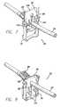
- FIG. 5shows the operation of the platen on the release tab of the flow stop, and the sear and hook of the door handle prior to the slide clamp of the flow stop being moved to the flow configuration
- FIG. 6shows the full engagement of the flow stop with the platen and the sear and hook of the door handle in position to return the slide clamp of the flow stop to the occluding position as the door is opened;
- FIG. 7is a perspective view of the flow stop in the occluding configuration showing its engagement with the tube;
- FIG. 8is a perspective view of the flow stop in the flow configuration showing its engagement with the tube
- FIG. 9is a perspective view of a platen in accordance with aspects of the invention.
- FIG. 10is a perspective view of the front of an infusion pump of FIGS. 1 through 3 with the platen removed so that the hinge of the door may be seen and the engagement surface of the door that contacts the platen to exert pressure on the platen, also shown in the floating hinge of the platen;
- FIG. 11is also a front perspective view of an infusion pump of FIGS. 1 through 3 with the platen in place on its floating hinge, and showing the datum pins on the bezel of the pumping mechanism and the contact datum surfaces of the platen positioned to engage the pins;
- FIG. 12shows the operation of the door handle in the disengaged position where it is moving into engagement with the flow stop, also showing the platen in engagement with the release tab of the flow stop;
- FIG. 13shows the door in contact with the platen and shows the door handle being closed against the door and coming into engagement with the flow stop to move it to the flow configuration;
- FIG. 14shows the door handle moving the flow stop to the flow configuration with the sear of the handle moving into position to engage the flow stop
- FIG. 15shows the flow stop placed into the flow configuration and the hook of the sear of the handle fully engaged with the slide clamp of the flow stop so that when the handle and door are opened, the sear will pull the slide clamp of the flow stop into the occluding configuration
- FIG. 16is a perspective view of the housing of the flow stop mounting portion of the infusion pump showing a sear detector and showing part of a flow stop detector;
- FIG. 17shows in schematic fashion the operation of the reflective sear detector of one embodiment.
- FIG. 18is a schematic diagram of the sear detector and flow stop detector circuits connected to a processor to provide an alert if the respective sear and flow stop are not present.
- FIG. 1a patient management system 20 having an infusion pump 22 in operative engagement with an intravenous (“IV”) administration tube 24 .
- a fluid source 26can be suspended from appropriate apparatus such as an IV pole 28 .
- the tube 24is connected between the fluid source 26 and the patient (not shown) so that the patient may receive the fluid of the fluid source at a rate controlled by the infusion pump 22 .
- the pumpincludes a front door 30 and a handle 32 that operates to lock the door in a closed position.
- a displaysuch as an LED display, exists on the door in this embodiment and may be used to display various information relevant to the pump, such as alerting messages.
- Control keys 36exist for programming the infusion pump as desired.
- the front dooris shown connected to the housing of the pump by means of a first hinge 38 . As is apparent from FIGS. 1 and 2, the hinge 38 of the door must be placed far enough forward so that the door 30 , which opens from right to left in the figures, can clear the device or module to which the pump is attached.
- This hinge placementpermits the pump 22 to be streamlined in size yet it can be connected on its left or right side to another module.
- an advanced programming module 40is attached to the left side of the infusion pump 22 .
- Other devices or modules, including another infusion pump,may be attached to the right side of the infusion pump 22 shown.
- the first hinge 38will permit the modules to be opened without interfering with the adjacent module.
- FIG. 3the infusion pump 22 of FIGS. 1 and 2 is shown in perspective view with the front door 30 open.
- a platen 42is mounted between the door 30 and the pumping mechanism 44 .
- the pumping mechanism 44is of the “four finger” type and includes an upstream occluder 46 , a primary pumping finger 48 , a downstream occluder 50 , and a secondary pumping finger 52 .
- the operation of four finger pumpsis well known to those skilled in the art and no further operational details are provided here.
- the IV tube 24also includes a flow stop 56 and the pump 22 also includes an air-in-line sensor 58 .
- the handle 32includes a latch arm 60 positioned to engage a yoke 62 located on the housing 64 of the pump. Engagement of the yoke by the latch arm will permit the door to remain locked in the closed position.
- the handle 32also includes a sear 66 having at least one hook 68 , and in the embodiment show, the sear has two hooks.
- IV tube 24 and its associated pumping segment 70are mounted across the pumping mechanism 44 by the engagement of an upstream fitment 72 with an upper bracket 74 and the engagement of the flow stop 56 with a lower flow stop bracket 76 .
- the pumping segment 70is positioned against the pumping mechanism 44 . Also, with this engagement, the pumping segment 70 is placed under slight tension between the upstream fitment 72 and the flow stop 56 to ensure a snug fit between the pumping segment 70 and the four finger pumping mechanism 44 .
- the flow stop 56consists generally of a relatively open, box shaped base 78 and a mating slide clamp 80 . Both parts can be formed by injection molding from various plastic materials.
- the solid rectangular body of the slide clamp 80is shaped and sized to fit slidingly within the base 78 .
- the base 78has a tower 82 formed on the top surface of the base with the tower 82 extending upwardly from the base 78 substantially perpendicular to the base.
- the top end of the toweris formed as a male tube connector 84 over which a pumping tube can be attached.
- the open bottom end of the tower 82is attached to the base 78 and it is formed as a female tube connector into which an IV tube can be attached.
- the IV tube and the pumping tubecan be the same tube if desired, simply passing through the tower 82 .
- the slide clamp 80includes an elongated aperture 86 and is oriented so that the elongated dimension of the aperture is arranged on the slide clamp to be parallel to the direction of the relative sliding movement between the base and the slide clamp.
- Two side edges of the body of the slide clampare fitted with rails 88 that lie parallel to the direction of the relative sliding movement.
- the rails 88fit in a sliding fashion over two rail channels 90 in the top of the base and over two frames formed on the edge of the base. Alignment of the slide clamp 80 with the base 78 is accomplished by the fit of the rails 88 over the frames 90 , and by the fit of the body of the slide clamp between the frames.
- Two flexible cantilevered locking arms 92are molded into the top of the base, with their distal free ends 94 biased downwardly below the top surface of the base. Biasing of the free ends 94 downwardly is accomplished by molding the locking arms in a downwardly sloped configuration, but the biasing could also be accomplished by the use of springs or other means.
- a release tab 96is formed on the locking arms 92 , projecting upwardly from the locking arms substantially parallel to the longitudinal axis of the tower 82 . In the free state, when the locking arms are sloped downwardly relative to the top surface of the base, the release tab 96 is spaced away from the outer surface of the tower. The free ends of the locking arms can be flexed upwardly by pressing the release tab toward the tower. Without departing from aspects of the invention, one locking arm 92 can be used in place of the two shown, or each locking arm can have a separate release tab 96 .
- Two locking projections 98are molded on the top surface of the slide clamp with the locking projections taking the form of ramps.
- the locking projectionsare transversely positioned on the slide clamp to align with the free ends 94 of the locking arms 92 when the slide clamp is inserted into the base.
- the locking projectionsare also longitudinally positioned to prevent the slide clamp from being inserted into the base far enough to move from its occluding position to its flow position.
- the elongated aperture 86 through the slide clamp 80has an open end 100 shaped essentially as a round hole with a sufficiently large diameter to allow the tube to pass through the open end without being occluded.
- the diameter of the open end 100is large enough to allow the tube to remain unrestricted.
- the other end of the apertureis a relatively narrow slot 102 .
- the width of the slot 102is sufficiently small that the tube passing through the slot 102 would be completely occluded and would remain occluded against a foreseeable range of fluid pressures in the tube.
- the range of pressure against which the tube would remain occludedwould include at least the static head anticipated during normal use of the infusion apparatus.
- the locking projections 98project upwardly from the top surface of the slide clamp 80 presenting a substantially vertical locking face to engage the free ends 94 of the locking arms 92 when the slide clamp is in its occluding configuration.
- one or more pulling projections 104project downwardly from the bottom surface of the slide clamp.
- Each of the pulling projections 104presents a substantially vertical pulling face that will interact with the sear 66 of the door handle 32 (not shown) to pull the slide clamp 80 partially out of engagement with the base 78 into the occluded configuration (FIG. 7) before the door 30 (not shown) is opened.
- the body of the slide clamp 80also presents a substantially vertical pushing face 106 on one end, against which the door of the housing pushes to fully insert the slide clamp into the base when the door is closed. Pushing the slide clamp into full insertion with the base moves the slide clamp from its occluding configuration to its flow configuration.
- FIGS. 5 and 6show in general how the flow stop 56 interacts with the platen 42 .
- FIG. 5shows the slide clamp 80 in its occluding configuration relative to the base 78 with the slide clamp partially withdrawn from the base and the free ends 94 of the locking arms engaging the locking projections 98 to hold the slide clamp in its occluding configuration. This position of the slide clamp is achieved before the door is opened and maintained until after the door is closed.
- FIG. 6shows the slide clamp in its flow configuration with the slide clamp fully inserted within the base and the free ends 94 of the locking arms 92 flexed upwardly a sufficient amount to clear the locking projections 98 .
- FIGS. 5 and 6Operative elements are shown schematically in FIGS. 5 and 6.
- a flow stop actuator portion 108 of the platen 42is positioned to contact the release tab 96 as the door is moved to the closed position and to press the release tab toward the tower 82 .
- a pushing boss 110 formed on the handle(not shown) is positioned to contact the pushing face 106 on the slide clamp 80 as the handle is engaged to push the slide clamp from its occluding configuration (FIG. 7) to its flow configuration (FIG. 8 ).
- one or more pulling hooks 68are formed on the sear 66 and are positioned to contact the pulling projections 104 as the handle is disengaged from the door to open the door and pull the slide clamp 80 from its flow configuration to its occluding configuration.
- flow stop 56Further details of the flow stop 56 may be obtained from U.S. Pat. No. 5,453,098 which is incorporated herein by reference. Additionally, such a flow stop is available from ALARIS Medical Systems, Inc. under the trademark Flo-Stop®.
- a body portion 112includes an extension located and dimensioned to act as a flow stop actuator portion 108 .
- the actuator portion 108is offset from the body portion and is separately hinged 112 for support. It is offset to make necessary contact with the release tab 96 of the flow stop (FIG. 6) so that the flow stop 56 may be moved to its flow configuration (FIG. 8 ).
- the platenalso includes a series of interconnected raised ribs that distribute the load provided by the closed door. In particular, there is a raised load distribution rib 114 interconnected with the series of ribs to make contact with the inner surface of the door, and in particular, with a pressure surface 116 (FIG.
- the platenalso includes a plurality of contact datum surfaces 118 (two of which may be seen in FIG. 9) disposed on the platen at positions selected to engage datum pins formed on the pumping mechanism bezel, as will be discussed in more detail below.
- the surfaces 118permit the platen to be precisely located a desired distance away from the pumping mechanism 44 when the door 30 is closed.
- the platenwas formed of thermoset material having a low creep value.
- One such materialis a glass-filled liquid crystal polymer (LCP).
- the door 30 of the pumpis mounted forward to a degree that permits the infusion pump to be mounted closely adjacent to other such devices. Because of this door mounting feature, close side-by-side mounting of devices may be achieved yet their front doors may be opened for access without interfering with operation of the adjacent devices. However, such forward door mounting results in a configuration where the door is at an unacceptable angle to the fluid tube 24 . If the inner surface of the door were attempted to be used to operate as a platen to the pumping mechanism, it would tend to roll the tube 24 out of position as the door is closed. Instead, in accordance with an aspect of the invention, a separate platen is used and is mounted on a separate hinge closer to the pumping mechanism.
- the separate or second hingepermits placement of the platen in relation to the pumping mechanism to minimize lateral displacement of the tube (rolling of the tube) as the door closes.
- a set of datum pins formed on the bezel of the pumping mechanism and a counterpart set of contact datum surfaces 118 formed on the platenpermit accurate placement of the platen in relation to the pumping mechanism. Consequently, a less precise, lower tolerance “floating hinge” 112 may be used to mount the platen to the housing. Tolerances are controlled solely during molding of the datum pins on the bezel and the contact datum surfaces of the platen.
- FIG. 10a perspective view of the pump 22 is shown with the platen removed so that the hinge of the outer door 30 may be seen.
- the housing floating hinge 120can be seen and is used to receive the counterpart hinge of the platen.
- four datum pins 122located on the bezel 124 surrounding the pumping mechanism 44 .
- the yoke 62is spring biased towards the housing 64 .
- the spring (not shown) forceis strong enough to hold the door 30 closed against the platen such that the platen applies enough pressure against the tube 24 so that the pumping mechanism is always occluding the tube once engaged.
- the spring forceis also strong enough to keep the platen against the datum pins 122 during use of the pump, regardless of the pressure of the fluids pumped through the tube 24 .
- FIG. 11is identical to FIG. 10 except that the platen 42 is shown in position in the pump.
- the first hinge 38 with which the door 30 is mounted to the pumpis more forward that the second hinge 120 with which the platen is mounted to the pump.
- the yoke 62is clearly visible and the latch arm 60 of the handle which is used to engage the yoke to hold the door in the closed position.
- the datum pins 120are also visible.
- FIGS. 12 through 15present the operation of the door handle and its specific components in controlling the configuration of the flow stop 56 .
- the pivoting handle 32captures the yoke 62 with the latch arm 60
- the sear 66 and pushing boss 110are moved toward the flow stop 56 , as shown in FIG. 12 .
- the flow stop actuation portion 108 of the platen 42has already engaged the release tab 96 of the flow stop base 78 and moved it to the released position.
- the platenhas already engaged the tube 24 with the pumping mechanism 44 so that the tube has become occluded by the pumping mechanism. Thus free flow through the tube is not possible.
- the slide clamp 80 of the flow stopmay now be moved to the flow configuration.
- FIG. 13presents more detail of the platen 42 showing the pressure distribution rib 114 in contact with the door pressure surface 116 .
- the searhas begun moving into position beneath the slide clamp but the pushing boss 110 has not yet come into contact with the pushing face of the slide clamp 80 .
- FIG. 14shows the pushing boss 110 in contact with the pushing face 106 of the slide clamp and pushing the slide clamp from the occluding configuration to the flow configuration.
- FIG. 15shows the handle fully engaged with the housing thereby locking the door in the closed position.
- the slide clamp 80has been fully moved into the base 78 of the flow stop 56 and into the flow configuration.
- Flowis now fully controlled by the pumping mechanism.
- the hook 68 of the sear 66has engaged the pulling projection 104 of the slide clamp so that once the handle is pulled outward to open the door, the hook of the sear will first move the slide clamp to the occluding configuration as shown in FIG. 12 thus preventing free flow once the pumping mechanism is disengaged from the tube once the door is opened.
- FIG. 16a sensor module 126 is shown.
- the placement of the module in the infusion pumpis shown in FIG. 3 by numeral 126 .
- the moduleincludes a flow stop mounting slot 128 into which the flow stop is slid during the process of mounting the tube 24 to the pump 22 . This is also shown in FIG. 3 .
- Shown also in FIG. 16is the air-in-line sensor 58 that is included in the sensor module 126 .
- the sensor modulealso includes a sear slot 130 into which the sear 66 of the handle moves as the door is closed.
- the sear slot 130also includes guide ramps 132 (only one of which can be seen) that assist in forcing the hooks 68 of the sear 66 into contact with the pulling projections 104 of the slide clamp 80 (see FIG. 6 ).
- the module 126includes a flow stop detector apparatus mounted in conjunction with the flow stop mounting slot 128 .
- the flow stop detector apparatusincludes an emitter 134 mounted on one side of the flow stop slot 128 and a receiver (not shown) mounted on the opposite side of the flow stop slot 128 . Placing the flow stop properly into the flow stop slot 128 will break the beam between the emitter and the receiver thereby indicating the presence of a flow stop.
- the module 126also includes a sear detector 136 mounted so as to detect the presence of a sear.
- the sear detectoris reflective in construction and is shown in schematic form in FIG. 17 .
- the sear detector 136includes an emitter 138 and a receiver 140 .
- the beam from the emitter 138will be reflected by the sear to the receiver 140 indicating the presence of a sear.
- the emitter and receiverare pointed or “focused” to a particular location at which a sear is expected.
- the searis either formed of a reflective material, such as polymer having a reflective pigment, or is coated with a reflective material. Detecting the presence of the sear 66 also indicates that the door is closed and latched because it is highly unlikely that the sear could be detected by the sear detector 136 unless such a door configuration exists.
- the sensor moduleprovides two systems to avoid a free flow condition.
- the first systemchecks for the very existence of a flow stop, and the second system checks for the existence of a sear that can activate the flow stop to the occluding configuration when the door is opened. If either detector indicates the nonexistence of the respective item, the operator can be notified that a possible free flow condition could occur if the door of the pump is opened. The operator may then apply a manual clamp to the tube 24 downstream of the pump before the pump door is opened to manually avoid a free flow condition.
- a system using the flow stop detector and the sear detectoris shown in FIG. 18.
- a processor 142monitors the sear detector 136 and the flow stop detector 134 (numeral 134 is used to collectively indicate the flow stop detector here) and if either indicates that the respective component is not present, the processor may provide an alert 144 .
- Such an alertmay take a visual form or an audible form or both.
- a visual alertmay be provided on the display 34 of the infusion pump itself or elsewhere, such as a display 144 of an advanced programming module 40 (see FIG. 2 ).
Landscapes
- Health & Medical Sciences (AREA)
- Heart & Thoracic Surgery (AREA)
- Animal Behavior & Ethology (AREA)
- General Health & Medical Sciences (AREA)
- Anesthesiology (AREA)
- Biomedical Technology (AREA)
- Hematology (AREA)
- Life Sciences & Earth Sciences (AREA)
- Veterinary Medicine (AREA)
- Engineering & Computer Science (AREA)
- Public Health (AREA)
- Pulmonology (AREA)
- Vascular Medicine (AREA)
- Infusion, Injection, And Reservoir Apparatuses (AREA)
- Reciprocating Pumps (AREA)
- Sampling And Sample Adjustment (AREA)
- Perforating, Stamping-Out Or Severing By Means Other Than Cutting (AREA)
- External Artificial Organs (AREA)
Abstract
Description
Claims (54)
Priority Applications (26)
| Application Number | Priority Date | Filing Date | Title |
|---|---|---|---|
| US09/848,790US6629955B2 (en) | 2001-05-04 | 2001-05-04 | Medical instrument flow stop interface |
| KR1020037014389AKR100870228B1 (en) | 2001-05-04 | 2002-04-11 | Improved medical device flow stopper interface |
| DE60220663TDE60220663T2 (en) | 2001-05-04 | 2002-04-11 | Peristaltic infusion pump with flow stop and pressure plate for the infusion tube |
| MXPA03010076AMXPA03010076A (en) | 2001-05-04 | 2002-04-11 | Improved medical instrument flow stop interface. |
| AT02769262TATE364415T1 (en) | 2001-05-04 | 2002-04-11 | PERISTALTIC INFUSION PUMP WITH FLOWSTOP AND PRESSURE PLATE FOR THE INFUSION TUBE |
| CZ20033292ACZ20033292A3 (en) | 2001-05-04 | 2002-04-11 | Improved medical instrument flow stop interface |
| HK04105259.1AHK1063163B (en) | 2001-05-04 | 2002-04-11 | Peristaltic infusion pump with flowstop and platen for the infusion tube |
| RU2003135223/14ARU2286179C2 (en) | 2001-05-04 | 2002-04-11 | Advanced conjugation of lock of flow for medical instruments |
| HU0400062AHU226969B1 (en) | 2001-05-04 | 2002-04-11 | Improved medical instrument flow stop interface |
| CA002444403ACA2444403C (en) | 2001-05-04 | 2002-04-11 | Improved medical instrument flow stop interface |
| NZ528962ANZ528962A (en) | 2001-05-04 | 2002-04-11 | Improved medical instrument flow stop interface |
| DK02769262TDK1383559T3 (en) | 2001-05-04 | 2002-04-11 | Peristaltic infusion pump with flow stop and pressure plate for the infusion line |
| AU2002307242AAU2002307242B2 (en) | 2001-05-04 | 2002-04-11 | Improved medical instrument flow stop interface |
| JP2002587007AJP4394883B2 (en) | 2001-05-04 | 2002-04-11 | Improved medical device anti-flow boundary area |
| PCT/US2002/011317WO2002089876A1 (en) | 2001-05-04 | 2002-04-11 | Improved medical instrument flow stop interface |
| PL363987APL203267B1 (en) | 2001-05-04 | 2002-04-11 | Improved medical instrument flow stop interface |
| PT02769262TPT1383559E (en) | 2001-05-04 | 2002-04-11 | Peristaltic infusion pump with flowstop and platen for the infusion tube |
| CNB028093658ACN1278746C (en) | 2001-05-04 | 2002-04-11 | Improved medical instrument flow step interface |
| EP02769262AEP1383559B1 (en) | 2001-05-04 | 2002-04-11 | Peristaltic infusion pump with flowstop and platen for the infusion tube |
| ES02769262TES2288559T3 (en) | 2001-05-04 | 2002-04-11 | PERISTALTIC INFUSION PUMP WITH FLOW INTERRUPTION AND A PLATE FOR THE INFUSION TUBE. |
| NO20034904ANO20034904L (en) | 2001-05-04 | 2003-11-03 | Improved streaming punch interface for medical instruments |
| CY20071101076TCY1106812T1 (en) | 2001-05-04 | 2007-08-09 | PERISTALTIC INJECTION PUMP WITH BLOCK ELEMENT AND PRESSURE PLATE FOR INJECTION PIPE |
| JP2009117122AJP2009172443A (en) | 2001-05-04 | 2009-05-14 | Improved medical instrument flow stop interface |
| NO20110189ANO20110189L (en) | 2001-05-04 | 2011-02-03 | Device for controlling a flow stop |
| NO20111132ANO20111132L (en) | 2001-05-04 | 2011-08-17 | Improved flow stop interface for medical instruments |
| NO20111131ANO20111131L (en) | 2001-05-04 | 2011-08-17 | Improved flow stop interface for medical instruments |
Applications Claiming Priority (1)
| Application Number | Priority Date | Filing Date | Title |
|---|---|---|---|
| US09/848,790US6629955B2 (en) | 2001-05-04 | 2001-05-04 | Medical instrument flow stop interface |
Publications (2)
| Publication Number | Publication Date |
|---|---|
| US20020165503A1 US20020165503A1 (en) | 2002-11-07 |
| US6629955B2true US6629955B2 (en) | 2003-10-07 |
Family
ID=25304275
Family Applications (1)
| Application Number | Title | Priority Date | Filing Date |
|---|---|---|---|
| US09/848,790Expired - LifetimeUS6629955B2 (en) | 2001-05-04 | 2001-05-04 | Medical instrument flow stop interface |
Country Status (21)
| Country | Link |
|---|---|
| US (1) | US6629955B2 (en) |
| EP (1) | EP1383559B1 (en) |
| JP (2) | JP4394883B2 (en) |
| KR (1) | KR100870228B1 (en) |
| CN (1) | CN1278746C (en) |
| AT (1) | ATE364415T1 (en) |
| AU (1) | AU2002307242B2 (en) |
| CA (1) | CA2444403C (en) |
| CY (1) | CY1106812T1 (en) |
| CZ (1) | CZ20033292A3 (en) |
| DE (1) | DE60220663T2 (en) |
| DK (1) | DK1383559T3 (en) |
| ES (1) | ES2288559T3 (en) |
| HU (1) | HU226969B1 (en) |
| MX (1) | MXPA03010076A (en) |
| NO (4) | NO20034904L (en) |
| NZ (1) | NZ528962A (en) |
| PL (1) | PL203267B1 (en) |
| PT (1) | PT1383559E (en) |
| RU (1) | RU2286179C2 (en) |
| WO (1) | WO2002089876A1 (en) |
Cited By (38)
| Publication number | Priority date | Publication date | Assignee | Title |
|---|---|---|---|---|
| US20060011873A1 (en)* | 2004-07-16 | 2006-01-19 | Clarke Christopher J | Automatic clamp apparatus for IV infusion sets used in pump devices |
| US20060129110A1 (en)* | 2004-07-16 | 2006-06-15 | Cardinal Health U.K. 305, Limited | Automatic clamp apparatus having lateral motion resistance for IV infusion sets |
| USD556904S1 (en) | 2004-07-16 | 2007-12-04 | Cardinal Health 303, Inc. | Automatic clamp device with offset release tab |
| US20080004567A1 (en)* | 2002-06-17 | 2008-01-03 | Iradimed Corporation | Non-magnetic medical infusion device |
| US20090076461A1 (en)* | 2007-07-13 | 2009-03-19 | Iradimed Corporation | System and method for communication with an infusion device |
| US20090227970A1 (en)* | 2006-10-17 | 2009-09-10 | C.R. Bard, Inc. | Waste management system |
| US20090254034A1 (en)* | 2008-04-01 | 2009-10-08 | Kent Beck | Safety occluder and method of use |
| US20090264857A1 (en)* | 2005-11-10 | 2009-10-22 | Iradimed Corporation | Liquid infusion apparatus |
| US20090275897A1 (en)* | 2008-04-30 | 2009-11-05 | Namiki Seimitsu Houseki Kabushiki Kaisha | Tubing misload detection mechanism for an infusion pump |
| US20090306592A1 (en)* | 2008-04-30 | 2009-12-10 | Namiki Seimitsu Houseki Kabushiki Kaisha | Infusion pump |
| US20100040481A1 (en)* | 2006-11-08 | 2010-02-18 | Fresenius Vial Sas | Device for controlling the opening and closing of a clamp in a positive displacement pump |
| USD635255S1 (en) | 2010-08-06 | 2011-03-29 | WalkMed Infusion LLC | Combination slide clamp and occlusion clamp actuator |
| US8062008B2 (en)* | 2007-09-27 | 2011-11-22 | Curlin Medical Inc. | Peristaltic pump and removable cassette therefor |
| US8262642B2 (en) | 2004-10-12 | 2012-09-11 | Iradimed Corporation | IV fluid infusion assembly |
| US8465464B2 (en) | 2010-08-06 | 2013-06-18 | WalkMed Infusion LLC | Infusion pump and slide clamp apparatus and method |
| US8469933B2 (en) | 2011-03-18 | 2013-06-25 | Zyno Medical Llc | Pump activated pinch clamp |
| US8777912B2 (en) | 2007-07-22 | 2014-07-15 | C. R. Bard, Inc. | Waste management system |
| US8961155B2 (en) | 2011-02-19 | 2015-02-24 | Douglas Shipman | Peristaltic linear pump and method of operation |
| US9017297B2 (en) | 2010-08-06 | 2015-04-28 | WalkMed Infusion LLC | Infusion pump and method which inhibits unintended tubing withdrawal |
| US9144644B2 (en) | 2011-08-02 | 2015-09-29 | Baxter International Inc. | Infusion pump with independently controllable valves and low power operation and methods thereof |
| US20150275887A1 (en)* | 2012-11-14 | 2015-10-01 | Namiki Precision Singapore Pte. Ltd. | Tubing pump |
| US9677555B2 (en) | 2011-12-21 | 2017-06-13 | Deka Products Limited Partnership | System, method, and apparatus for infusing fluid |
| US9675756B2 (en) | 2011-12-21 | 2017-06-13 | Deka Products Limited Partnership | Apparatus for infusing fluid |
| US10265463B2 (en) | 2014-09-18 | 2019-04-23 | Deka Products Limited Partnership | Apparatus and method for infusing fluid through a tube by appropriately heating the tube |
| US10455923B1 (en)* | 2018-03-27 | 2019-10-29 | Heather Domingues | Enteral feeding system |
| US10590678B2 (en) | 2015-10-07 | 2020-03-17 | B. Braun Avitum Ag | Locking state detection apparatus |
| US10648564B2 (en) | 2016-12-30 | 2020-05-12 | Baxter International Inc. | Infusion pump door seal for vertical intravenous tubes |
| US20200164199A1 (en)* | 2017-07-18 | 2020-05-28 | B. Braun Melsungen Ag | Apparatus and method for opening and closing an infusion tube clamp |
| US10758669B2 (en) | 2016-12-30 | 2020-09-01 | Baxter International Inc. | Anti-occlusion intravenous tube port |
| US11147913B2 (en)* | 2018-12-06 | 2021-10-19 | Curlin Medical Inc. | Platen for peristaltic infusion pump |
| US20210369572A1 (en)* | 2019-07-01 | 2021-12-02 | Medline Industries, Inc. | Feeding set and enteral feeding pump assembly |
| US11202859B2 (en)* | 2019-11-20 | 2021-12-21 | B Braun Medical Inc. | Cassette with free flow prevention for infusion pump |
| US11268506B2 (en) | 2017-12-22 | 2022-03-08 | Iradimed Corporation | Fluid pumps for use in MRI environment |
| US11295846B2 (en) | 2011-12-21 | 2022-04-05 | Deka Products Limited Partnership | System, method, and apparatus for infusing fluid |
| US11707615B2 (en) | 2018-08-16 | 2023-07-25 | Deka Products Limited Partnership | Medical pump |
| US11904133B2 (en) | 2017-12-19 | 2024-02-20 | Smiths Medical Asd, Inc. | Infusion pump systems and methods for administration sets |
| WO2024182082A1 (en)* | 2023-03-02 | 2024-09-06 | B. Braun Medical Inc. | Latch for capturing and securing a cassette to a medical device |
| US12098738B2 (en) | 2011-12-21 | 2024-09-24 | Deka Products Limited Partnership | System, method, and apparatus for clamping |
Families Citing this family (65)
| Publication number | Priority date | Publication date | Assignee | Title |
|---|---|---|---|---|
| US6722865B2 (en) | 2001-09-07 | 2004-04-20 | Terumorcardiovascular Systems Corporation | Universal tube clamp assembly |
| IL152865A0 (en)* | 2002-11-14 | 2003-06-24 | Q Core Ltd | Peristalic pump |
| EP2316328B1 (en) | 2003-09-15 | 2012-05-09 | Super Dimension Ltd. | Wrap-around holding device for use with bronchoscopes |
| EP2113189B1 (en) | 2003-09-15 | 2013-09-04 | Covidien LP | System of accessories for use with bronchoscopes |
| US8764725B2 (en) | 2004-02-09 | 2014-07-01 | Covidien Lp | Directional anchoring mechanism, method and applications thereof |
| GB0416006D0 (en)* | 2004-07-16 | 2004-08-18 | Alaris Medical U K Ltd | Infusion apparatus |
| DK1616588T3 (en)* | 2004-07-17 | 2006-07-24 | Codan Holding Gmbh | Device for interconnecting an intravenous tube with an infusion pump |
| US8308457B2 (en) | 2004-11-24 | 2012-11-13 | Q-Core Medical Ltd. | Peristaltic infusion pump with locking mechanism |
| IL165365A0 (en) | 2004-11-24 | 2006-01-15 | Q Core Ltd | Finger-type peristaltic pump |
| US9717834B2 (en) | 2011-05-24 | 2017-08-01 | Deka Products Limited Partnership | Blood treatment systems and methods |
| US7611498B2 (en)* | 2006-05-18 | 2009-11-03 | Codan Holding Gmbh | Arrangement for the coupling of an intravenous tube with infusion pump |
| US8535025B2 (en) | 2006-11-13 | 2013-09-17 | Q-Core Medical Ltd. | Magnetically balanced finger-type peristaltic pump |
| IL179231A0 (en) | 2006-11-13 | 2007-03-08 | Q Core Ltd | A finger-type peristaltic pump comprising a ribbed anvil |
| IL179234A0 (en)* | 2006-11-13 | 2007-03-08 | Q Core Ltd | An anti-free flow mechanism |
| US9028691B2 (en) | 2007-02-27 | 2015-05-12 | Deka Products Limited Partnership | Blood circuit assembly for a hemodialysis system |
| DE102007032090B4 (en)* | 2007-07-09 | 2016-08-11 | Otto Bock Healthcare Gmbh | Orthopedic fluid damper |
| US8905920B2 (en) | 2007-09-27 | 2014-12-09 | Covidien Lp | Bronchoscope adapter and method |
| US10201647B2 (en) | 2008-01-23 | 2019-02-12 | Deka Products Limited Partnership | Medical treatment system and methods using a plurality of fluid lines |
| US11833281B2 (en) | 2008-01-23 | 2023-12-05 | Deka Products Limited Partnership | Pump cassette and methods for use in medical treatment system using a plurality of fluid lines |
| US8932207B2 (en) | 2008-07-10 | 2015-01-13 | Covidien Lp | Integrated multi-functional endoscopic tool |
| US8371832B2 (en) | 2009-12-22 | 2013-02-12 | Q-Core Medical Ltd. | Peristaltic pump with linear flow control |
| US8142400B2 (en)* | 2009-12-22 | 2012-03-27 | Q-Core Medical Ltd. | Peristaltic pump with bi-directional pressure sensor |
| CN102114279A (en)* | 2009-12-31 | 2011-07-06 | 北京谊安医疗系统股份有限公司 | Infusion pump |
| WO2013095459A1 (en)* | 2011-12-21 | 2013-06-27 | Deka Products Limited Partnership | System, method, and apparatus for electronic patient care |
| US9457158B2 (en) | 2010-04-12 | 2016-10-04 | Q-Core Medical Ltd. | Air trap for intravenous pump |
| US10582834B2 (en) | 2010-06-15 | 2020-03-10 | Covidien Lp | Locatable expandable working channel and method |
| US20120004624A1 (en)* | 2010-06-30 | 2012-01-05 | Carefusion 303, Inc. | Enhanced anti-flow protection for an intravenous set |
| US9674811B2 (en) | 2011-01-16 | 2017-06-06 | Q-Core Medical Ltd. | Methods, apparatus and systems for medical device communication, control and localization |
| JP2012200422A (en)* | 2011-03-25 | 2012-10-22 | Terumo Corp | Infusion pump |
| US9726167B2 (en) | 2011-06-27 | 2017-08-08 | Q-Core Medical Ltd. | Methods, circuits, devices, apparatuses, encasements and systems for identifying if a medical infusion system is decalibrated |
| FR2978919B1 (en)* | 2011-08-09 | 2014-09-12 | Ace Dev Solution | MULTIVOIE PILOT BOX |
| US9050447B2 (en)* | 2011-11-23 | 2015-06-09 | Carefusion 303, Inc. | Positive bolus clamp |
| US9746093B2 (en)* | 2011-12-21 | 2017-08-29 | Deka Products Limited Partnership | Flow meter and related system and apparatus |
| CN116370749A (en)* | 2012-05-24 | 2023-07-04 | 德卡产品有限公司 | Devices for infusion of fluids |
| US9364655B2 (en)* | 2012-05-24 | 2016-06-14 | Deka Products Limited Partnership | Flexible tubing occlusion assembly |
| EP2668921B1 (en)* | 2012-06-01 | 2015-08-12 | Zimmer Spine | Device for fixing a bony structure to a support member |
| US9855110B2 (en) | 2013-02-05 | 2018-01-02 | Q-Core Medical Ltd. | Methods, apparatus and systems for operating a medical device including an accelerometer |
| US9468714B2 (en) | 2013-03-14 | 2016-10-18 | Carefusion 303, Inc. | Memory and identification associated with IV set |
| US20140271246A1 (en)* | 2013-03-14 | 2014-09-18 | Carefusion 303, Inc. | Cooperation of platen and pump cassette for pump device |
| US9968739B2 (en) | 2013-03-14 | 2018-05-15 | Carefusion 303, Inc. | Rotary valve for a disposable infusion set |
| US20140271247A1 (en)* | 2013-03-14 | 2014-09-18 | Carefusion 303, Inc. | Infusion pump configured to engage a sensor with tubing |
| US10226571B2 (en) | 2013-03-14 | 2019-03-12 | Carefusion 303, Inc. | Pump segment placement |
| JP6102520B2 (en)* | 2013-05-29 | 2017-03-29 | ニプロ株式会社 | Medical instruments |
| RU2534632C1 (en)* | 2013-05-31 | 2014-12-10 | Закрытое акционерное общество Научно-производственный комплекс "КБ ВЗЛЕТ" | Controlled valve for clamping flexible pipeline of donated blood component separator and autoblood transfusion apparatus |
| JP6295127B2 (en)* | 2014-04-09 | 2018-03-14 | アトムメディカル株式会社 | Infusion tube set |
| JP6401931B2 (en)* | 2014-04-09 | 2018-10-10 | アトムメディカル株式会社 | Infusion device |
| US10952593B2 (en) | 2014-06-10 | 2021-03-23 | Covidien Lp | Bronchoscope adapter |
| US10426555B2 (en) | 2015-06-03 | 2019-10-01 | Covidien Lp | Medical instrument with sensor for use in a system and method for electromagnetic navigation |
| CN106955807B (en) | 2016-01-12 | 2019-07-05 | 固瑞克明尼苏达有限公司 | Integrated pump guard and control interlock |
| DE102016102782A1 (en) | 2016-02-17 | 2017-09-14 | B. Braun Avitum Ag | Dialysis membrane and process for its preparation |
| CN106064127B (en)* | 2016-07-20 | 2023-10-27 | 梁启明 | Catheter external gluing device |
| DE102017103852A1 (en) | 2017-02-24 | 2018-08-30 | B. Braun Melsungen Aktiengesellschaft | Safety fluid line system for a medical hose pump, peristaltic pump and unit thereof |
| DE102017111299A1 (en)* | 2017-05-23 | 2018-11-29 | B. Braun Melsungen Ag | Infusion pump with a different operating conditions ingestible pump module |
| US10549032B2 (en)* | 2017-06-27 | 2020-02-04 | Curlin Medical Inc. | Infusion pump latch mechanism and associated free-flow protection device |
| WO2019057467A1 (en)* | 2017-09-20 | 2019-03-28 | Fresenius Vial Sas | Medical device having a detachable cover element |
| WO2019125898A1 (en)* | 2017-12-20 | 2019-06-27 | Kci Licensing, Inc. | Combination hanger arm extension and pump cover for a wound therapy device |
| TWI674120B (en)* | 2018-06-14 | 2019-10-11 | 英華達股份有限公司 | Infusion equipment |
| USD920504S1 (en) | 2019-07-01 | 2021-05-25 | Medline Industries, Inc. | Valve |
| ES2933693T3 (en) | 2019-11-18 | 2023-02-13 | Eitan Medical Ltd | Rapid test for medical pump |
| US20210369962A1 (en)* | 2020-05-27 | 2021-12-02 | Carefusion 303, Inc. | Infusion pump sensing system |
| JP7463892B2 (en)* | 2020-07-22 | 2024-04-09 | ニプロ株式会社 | Finger pump and finger pump unit |
| CN111840697A (en)* | 2020-07-28 | 2020-10-30 | 首都医科大学附属北京儿童医院 | Vertical pump double rail synchronous infusion pump |
| CN112316245B (en)* | 2020-10-30 | 2021-07-27 | 深圳市好克医疗仪器股份有限公司 | Manual liquid stopping mechanism and liquid stopping equipment |
| JP7733676B2 (en)* | 2020-12-16 | 2025-09-03 | テルモ株式会社 | infusion pump |
| US20230099958A1 (en) | 2021-09-29 | 2023-03-30 | Medical Components, Inc. | Locking Slide Clamp |
Citations (5)
| Publication number | Priority date | Publication date | Assignee | Title |
|---|---|---|---|---|
| US4460358A (en) | 1980-11-07 | 1984-07-17 | Ivac Corporation | Combined load and latch mechanism for fluid flow control apparatus |
| US4689043A (en) | 1986-03-19 | 1987-08-25 | Imed Corporation | IV tube activator |
| US5453098A (en)* | 1994-05-09 | 1995-09-26 | Imed Corporation | Two step IV fluid flow stop |
| US5478211A (en) | 1994-03-09 | 1995-12-26 | Baxter International Inc. | Ambulatory infusion pump |
| US5482446A (en)* | 1994-03-09 | 1996-01-09 | Baxter International Inc. | Ambulatory infusion pump |
Family Cites Families (1)
| Publication number | Priority date | Publication date | Assignee | Title |
|---|---|---|---|---|
| US5336180A (en)* | 1990-04-24 | 1994-08-09 | Science Incorporated | Closed drug delivery system |
- 2001
- 2001-05-04USUS09/848,790patent/US6629955B2/ennot_activeExpired - Lifetime
- 2002
- 2002-04-11ESES02769262Tpatent/ES2288559T3/ennot_activeExpired - Lifetime
- 2002-04-11CACA002444403Apatent/CA2444403C/ennot_activeExpired - Lifetime
- 2002-04-11CZCZ20033292Apatent/CZ20033292A3/enunknown
- 2002-04-11MXMXPA03010076Apatent/MXPA03010076A/enactiveIP Right Grant
- 2002-04-11WOPCT/US2002/011317patent/WO2002089876A1/enactiveIP Right Grant
- 2002-04-11CNCNB028093658Apatent/CN1278746C/ennot_activeExpired - Lifetime
- 2002-04-11RURU2003135223/14Apatent/RU2286179C2/enactive
- 2002-04-11DEDE60220663Tpatent/DE60220663T2/ennot_activeExpired - Lifetime
- 2002-04-11PTPT02769262Tpatent/PT1383559E/enunknown
- 2002-04-11DKDK02769262Tpatent/DK1383559T3/enactive
- 2002-04-11NZNZ528962Apatent/NZ528962A/ennot_activeIP Right Cessation
- 2002-04-11JPJP2002587007Apatent/JP4394883B2/ennot_activeExpired - Lifetime
- 2002-04-11KRKR1020037014389Apatent/KR100870228B1/ennot_activeExpired - Fee Related
- 2002-04-11AUAU2002307242Apatent/AU2002307242B2/ennot_activeExpired
- 2002-04-11HUHU0400062Apatent/HU226969B1/ennot_activeIP Right Cessation
- 2002-04-11ATAT02769262Tpatent/ATE364415T1/enactive
- 2002-04-11EPEP02769262Apatent/EP1383559B1/ennot_activeExpired - Lifetime
- 2002-04-11PLPL363987Apatent/PL203267B1/ennot_activeIP Right Cessation
- 2003
- 2003-11-03NONO20034904Apatent/NO20034904L/ennot_activeApplication Discontinuation
- 2007
- 2007-08-09CYCY20071101076Tpatent/CY1106812T1/enunknown
- 2009
- 2009-05-14JPJP2009117122Apatent/JP2009172443A/enactivePending
- 2011
- 2011-02-03NONO20110189Apatent/NO20110189L/ennot_activeApplication Discontinuation
- 2011-08-17NONO20111131Apatent/NO20111131L/ennot_activeApplication Discontinuation
- 2011-08-17NONO20111132Apatent/NO20111132L/ennot_activeApplication Discontinuation
Patent Citations (5)
| Publication number | Priority date | Publication date | Assignee | Title |
|---|---|---|---|---|
| US4460358A (en) | 1980-11-07 | 1984-07-17 | Ivac Corporation | Combined load and latch mechanism for fluid flow control apparatus |
| US4689043A (en) | 1986-03-19 | 1987-08-25 | Imed Corporation | IV tube activator |
| US5478211A (en) | 1994-03-09 | 1995-12-26 | Baxter International Inc. | Ambulatory infusion pump |
| US5482446A (en)* | 1994-03-09 | 1996-01-09 | Baxter International Inc. | Ambulatory infusion pump |
| US5453098A (en)* | 1994-05-09 | 1995-09-26 | Imed Corporation | Two step IV fluid flow stop |
Cited By (99)
| Publication number | Priority date | Publication date | Assignee | Title |
|---|---|---|---|---|
| US20080004567A1 (en)* | 2002-06-17 | 2008-01-03 | Iradimed Corporation | Non-magnetic medical infusion device |
| US7753882B2 (en) | 2002-06-17 | 2010-07-13 | Iradimed Corporation | Non-magnetic medical infusion device |
| US20110009733A1 (en)* | 2002-06-17 | 2011-01-13 | Iradimed Corporation | Non-magnetic medical infusion device |
| US8150493B2 (en) | 2002-06-17 | 2012-04-03 | Iradimed Corporation | Patient infusion and imaging system |
| US8690829B2 (en) | 2002-06-17 | 2014-04-08 | Iradimed Corporation | Non-magnetic medical infusion device |
| USD556904S1 (en) | 2004-07-16 | 2007-12-04 | Cardinal Health 303, Inc. | Automatic clamp device with offset release tab |
| US20060011873A1 (en)* | 2004-07-16 | 2006-01-19 | Clarke Christopher J | Automatic clamp apparatus for IV infusion sets used in pump devices |
| US7303175B2 (en) | 2004-07-16 | 2007-12-04 | Cardinal Health 303, Inc. | Automatic clamp apparatus having lateral motion resistance for IV infusion sets |
| US7419133B2 (en) | 2004-07-16 | 2008-09-02 | Cardinal Health 303, Inc. | Automatic clamp apparatus for IV infusion sets used in pump devices |
| US20070102657A1 (en)* | 2004-07-16 | 2007-05-10 | Clarke Christopher J | Automatic clamp apparatus for IV infusion sets used in pump devices |
| US7124996B2 (en) | 2004-07-16 | 2006-10-24 | Cardinal Health 303, Inc. | Automatic clamp apparatus for IV infusion sets used in pump devices |
| US20060129110A1 (en)* | 2004-07-16 | 2006-06-15 | Cardinal Health U.K. 305, Limited | Automatic clamp apparatus having lateral motion resistance for IV infusion sets |
| US8262642B2 (en) | 2004-10-12 | 2012-09-11 | Iradimed Corporation | IV fluid infusion assembly |
| US9878089B2 (en) | 2005-11-10 | 2018-01-30 | Iradimed Corporation | Liquid infusion apparatus |
| US10821223B2 (en) | 2005-11-10 | 2020-11-03 | Iradimed Corporation | Liquid infusion apparatus |
| US11045600B2 (en) | 2005-11-10 | 2021-06-29 | Iradimed Corporation | Liquid infusion apparatus |
| US8469932B2 (en)* | 2005-11-10 | 2013-06-25 | Iradimed Corporation | Liquid infusion apparatus |
| US20090264857A1 (en)* | 2005-11-10 | 2009-10-22 | Iradimed Corporation | Liquid infusion apparatus |
| AU2006311456B2 (en)* | 2005-11-13 | 2012-08-09 | Carefusion 303, Inc. | Automatic clamp apparatus |
| WO2007056616A1 (en)* | 2005-11-13 | 2007-05-18 | Cardinal Health 303, Inc. | Automatic clamp apparatus |
| US9855163B2 (en) | 2006-10-17 | 2018-01-02 | C. R. Bard, Inc. | Waste management system |
| US9463110B2 (en) | 2006-10-17 | 2016-10-11 | C. R. Bard, Inc. | Waste management system |
| US8070736B2 (en) | 2006-10-17 | 2011-12-06 | C. R. Bard, Inc. | Waste management system |
| US8075539B2 (en) | 2006-10-17 | 2011-12-13 | C. R. Bard, Inc. | Waste management system |
| US9456920B2 (en) | 2006-10-17 | 2016-10-04 | C. R. Bard, Inc. | Waste management system |
| US20090227970A1 (en)* | 2006-10-17 | 2009-09-10 | C.R. Bard, Inc. | Waste management system |
| US8926577B2 (en) | 2006-10-17 | 2015-01-06 | C. R. Bard, Inc. | Waste management system |
| US10660784B2 (en) | 2006-10-17 | 2020-05-26 | C. R. Bard, Inc. | Waste management system |
| US8597266B2 (en) | 2006-10-17 | 2013-12-03 | C. R. Bard, Inc. | Waste management system |
| US8109898B2 (en)* | 2006-11-08 | 2012-02-07 | Fresenius Vial Sas | Device for controlling the opening and closing of a clamp in a positive displacement pump |
| US20100040481A1 (en)* | 2006-11-08 | 2010-02-18 | Fresenius Vial Sas | Device for controlling the opening and closing of a clamp in a positive displacement pump |
| US9861743B2 (en) | 2007-07-13 | 2018-01-09 | Iradimed Corporation | System and method for communication with an infusion device |
| US12251534B2 (en) | 2007-07-13 | 2025-03-18 | Iradimed Corporation | System for communication with an infusion device |
| US8500694B2 (en) | 2007-07-13 | 2013-08-06 | Iradimed Corporation | System and method for communication with an infusion device |
| US20090076461A1 (en)* | 2007-07-13 | 2009-03-19 | Iradimed Corporation | System and method for communication with an infusion device |
| US11291767B2 (en) | 2007-07-13 | 2022-04-05 | Iradimed Corporation | System and method for communication with an infusion device |
| US10617821B2 (en) | 2007-07-13 | 2020-04-14 | Iradimed Corporation | System and method for communication with an infusion device |
| US12246165B2 (en) | 2007-07-13 | 2025-03-11 | Iradimed Corporation | System and method for communication with an infusion device |
| US8105282B2 (en) | 2007-07-13 | 2012-01-31 | Iradimed Corporation | System and method for communication with an infusion device |
| US8777912B2 (en) | 2007-07-22 | 2014-07-15 | C. R. Bard, Inc. | Waste management system |
| US8062008B2 (en)* | 2007-09-27 | 2011-11-22 | Curlin Medical Inc. | Peristaltic pump and removable cassette therefor |
| US20090254034A1 (en)* | 2008-04-01 | 2009-10-08 | Kent Beck | Safety occluder and method of use |
| US9017296B2 (en)* | 2008-04-01 | 2015-04-28 | Zevex, Inc. | Safety occluder and method of use |
| US20090274567A1 (en)* | 2008-04-30 | 2009-11-05 | Namiki Seimitsu Houseki Kabushiki Kaisha | Tubing misload detection mechanism for an infusion pump |
| US8257066B2 (en)* | 2008-04-30 | 2012-09-04 | Namiki Seimitsu Houseki Kabushiki Kaisha | Tubing misload detection mechanism for an infusion pump |
| US9028456B2 (en)* | 2008-04-30 | 2015-05-12 | Namiki Seimitsu Houseki Kabushiki Kaisha | Infusion pump |
| US20090275897A1 (en)* | 2008-04-30 | 2009-11-05 | Namiki Seimitsu Houseki Kabushiki Kaisha | Tubing misload detection mechanism for an infusion pump |
| US20090306592A1 (en)* | 2008-04-30 | 2009-12-10 | Namiki Seimitsu Houseki Kabushiki Kaisha | Infusion pump |
| US8430654B2 (en)* | 2008-04-30 | 2013-04-30 | Namiki Seimitsu Houseki Kabushiki Kaisha | Tubing misload detection mechanism for an infusion pump |
| US9017297B2 (en) | 2010-08-06 | 2015-04-28 | WalkMed Infusion LLC | Infusion pump and method which inhibits unintended tubing withdrawal |
| USD635255S1 (en) | 2010-08-06 | 2011-03-29 | WalkMed Infusion LLC | Combination slide clamp and occlusion clamp actuator |
| US8465464B2 (en) | 2010-08-06 | 2013-06-18 | WalkMed Infusion LLC | Infusion pump and slide clamp apparatus and method |
| US8961155B2 (en) | 2011-02-19 | 2015-02-24 | Douglas Shipman | Peristaltic linear pump and method of operation |
| US8469933B2 (en) | 2011-03-18 | 2013-06-25 | Zyno Medical Llc | Pump activated pinch clamp |
| US10006454B2 (en) | 2011-08-02 | 2018-06-26 | Baxter International Inc. | Infusion pump with independently controllable valves and low power operation and methods thereof |
| US10865786B2 (en) | 2011-08-02 | 2020-12-15 | Baxter International Inc. | Infusion pump with independently controllable valves and low power operation and methods thereof |
| US10851773B2 (en) | 2011-08-02 | 2020-12-01 | Baxter International Inc. | Infusion pump with independently controllable valves and low power operation and methods thereof |
| US9144644B2 (en) | 2011-08-02 | 2015-09-29 | Baxter International Inc. | Infusion pump with independently controllable valves and low power operation and methods thereof |
| US11511038B2 (en) | 2011-12-21 | 2022-11-29 | Deka Products Limited Partnership | Apparatus for infusing fluid |
| US11373747B2 (en) | 2011-12-21 | 2022-06-28 | Deka Products Limited Partnership | Peristaltic pump |
| US12288604B2 (en) | 2011-12-21 | 2025-04-29 | Deka Products Limited Partnership | Peristaltic pump |
| US9677555B2 (en) | 2011-12-21 | 2017-06-13 | Deka Products Limited Partnership | System, method, and apparatus for infusing fluid |
| US10316834B2 (en) | 2011-12-21 | 2019-06-11 | Deka Products Limited Partnership | Peristaltic pump |
| US12098738B2 (en) | 2011-12-21 | 2024-09-24 | Deka Products Limited Partnership | System, method, and apparatus for clamping |
| US10753353B2 (en) | 2011-12-21 | 2020-08-25 | Deka Products Limited Partnership | Peristaltic pump |
| US12020798B2 (en) | 2011-12-21 | 2024-06-25 | Deka Products Limited Partnership | Peristaltic pump and related method |
| US10288057B2 (en) | 2011-12-21 | 2019-05-14 | Deka Products Limited Partnership | Peristaltic pump |
| US12002561B2 (en) | 2011-12-21 | 2024-06-04 | DEKA Research & Development Corp | System, method, and apparatus for infusing fluid |
| US10857293B2 (en) | 2011-12-21 | 2020-12-08 | Deka Products Limited Partnership | Apparatus for infusing fluid |
| US10202971B2 (en) | 2011-12-21 | 2019-02-12 | Deka Products Limited Partnership | Peristaltic pump |
| US11024409B2 (en) | 2011-12-21 | 2021-06-01 | Deka Products Limited Partnership | Peristaltic pump |
| US10202970B2 (en) | 2011-12-21 | 2019-02-12 | Deka Products Limited Partnership | System, method, and apparatus for infusing fluid |
| US11779703B2 (en) | 2011-12-21 | 2023-10-10 | Deka Products Limited Partnership | Apparatus for infusing fluid |
| US11756662B2 (en) | 2011-12-21 | 2023-09-12 | Deka Products Limited Partnership | Peristaltic pump |
| US11705233B2 (en) | 2011-12-21 | 2023-07-18 | Deka Products Limited Partnership | Peristaltic pump |
| US9675756B2 (en) | 2011-12-21 | 2017-06-13 | Deka Products Limited Partnership | Apparatus for infusing fluid |
| US11295846B2 (en) | 2011-12-21 | 2022-04-05 | Deka Products Limited Partnership | System, method, and apparatus for infusing fluid |
| US11348674B2 (en) | 2011-12-21 | 2022-05-31 | Deka Products Limited Partnership | Peristaltic pump |
| US20150275887A1 (en)* | 2012-11-14 | 2015-10-01 | Namiki Precision Singapore Pte. Ltd. | Tubing pump |
| US10012225B2 (en)* | 2012-11-14 | 2018-07-03 | Adamant Namiki Preccision Jewel Co., Ltd. | Tubing pump |
| US10265463B2 (en) | 2014-09-18 | 2019-04-23 | Deka Products Limited Partnership | Apparatus and method for infusing fluid through a tube by appropriately heating the tube |
| US11672903B2 (en) | 2014-09-18 | 2023-06-13 | Deka Products Limited Partnership | Apparatus and method for infusing fluid through a tube by appropriately heating the tube |
| US10590678B2 (en) | 2015-10-07 | 2020-03-17 | B. Braun Avitum Ag | Locking state detection apparatus |
| US10648564B2 (en) | 2016-12-30 | 2020-05-12 | Baxter International Inc. | Infusion pump door seal for vertical intravenous tubes |
| US11739841B2 (en) | 2016-12-30 | 2023-08-29 | Baxter International Inc. | Infusion pump door seal for vertical intravenous tubes |
| US12036385B2 (en) | 2016-12-30 | 2024-07-16 | Baxter International Inc. | Anti-occlusion intravenous tube port |
| US10758669B2 (en) | 2016-12-30 | 2020-09-01 | Baxter International Inc. | Anti-occlusion intravenous tube port |
| US20200164199A1 (en)* | 2017-07-18 | 2020-05-28 | B. Braun Melsungen Ag | Apparatus and method for opening and closing an infusion tube clamp |
| US12042622B2 (en)* | 2017-07-18 | 2024-07-23 | B. Braun Melsungen Ag | Apparatus and method for opening and closing an infusion tube clamp |
| US11904133B2 (en) | 2017-12-19 | 2024-02-20 | Smiths Medical Asd, Inc. | Infusion pump systems and methods for administration sets |
| US11268506B2 (en) | 2017-12-22 | 2022-03-08 | Iradimed Corporation | Fluid pumps for use in MRI environment |
| US10455923B1 (en)* | 2018-03-27 | 2019-10-29 | Heather Domingues | Enteral feeding system |
| US11707615B2 (en) | 2018-08-16 | 2023-07-25 | Deka Products Limited Partnership | Medical pump |
| US12251532B2 (en) | 2018-08-16 | 2025-03-18 | Deka Products Limited Partnership | Medical pump |
| US11147913B2 (en)* | 2018-12-06 | 2021-10-19 | Curlin Medical Inc. | Platen for peristaltic infusion pump |
| US20210369572A1 (en)* | 2019-07-01 | 2021-12-02 | Medline Industries, Inc. | Feeding set and enteral feeding pump assembly |
| US12102600B2 (en)* | 2019-07-01 | 2024-10-01 | Medline Industries, Lp | Feeding set and enteral feeding pump assembly |
| US11202859B2 (en)* | 2019-11-20 | 2021-12-21 | B Braun Medical Inc. | Cassette with free flow prevention for infusion pump |
| WO2024182082A1 (en)* | 2023-03-02 | 2024-09-06 | B. Braun Medical Inc. | Latch for capturing and securing a cassette to a medical device |
Also Published As
Similar Documents
| Publication | Publication Date | Title |
|---|---|---|
| US6629955B2 (en) | Medical instrument flow stop interface | |
| AU2002307242A1 (en) | Improved medical instrument flow stop interface | |
| EP1951362B1 (en) | Automatic clamp apparatus | |
| EP0686405B1 (en) | Two step IV fluid flow stop | |
| EP1778338B1 (en) | Automatic clamp apparatus for iv infusion sets used in pump devices | |
| US20120004624A1 (en) | Enhanced anti-flow protection for an intravenous set | |
| HK1063163B (en) | Peristaltic infusion pump with flowstop and platen for the infusion tube | |
| HK1121077B (en) | Automatic clamp apparatus |
Legal Events
| Date | Code | Title | Description |
|---|---|---|---|
| AS | Assignment | Owner name:ALARIS MEDICAL SYSTEMS, INC., CALIFORNIA Free format text:ASSIGNMENT OF ASSIGNORS INTEREST;ASSIGNORS:MORRIS, MATTHEW G.;HURTADO, VICTOR R.;REEL/FRAME:011779/0108 Effective date:20010503 | |
| AS | Assignment | Owner name:ALARIS MEDICAL INC., CALIFORNIA Free format text:MERGER;ASSIGNOR:ALARIS MEDICAL SYSTEMS INC.;REEL/FRAME:014229/0718 Effective date:20030630 Owner name:ALARIS MEDICAL SYSTEMS, INC., CALIFORNIA Free format text:CHANGE OF NAME;ASSIGNOR:ALARIS MEDICAL INC.;REEL/FRAME:014234/0887 Effective date:20030630 Owner name:ALARIS MEDICAL SYSTEMS, INC., CALIFORNIA Free format text:SECURITY AGREEMENT;ASSIGNOR:HSBC BANK USA;REEL/FRAME:014231/0582 Effective date:20030630 Owner name:CITICORP NORTH AMERICA, INC., NEW YORK Free format text:SECURITY AGREEMENT;ASSIGNOR:ALARIS MEDICAL SYSTEMS, INC.;REEL/FRAME:014236/0724 Effective date:20030630 | |
| STCF | Information on status: patent grant | Free format text:PATENTED CASE | |
| AS | Assignment | Owner name:ALARIS MEDICAL SYSTEMS, INC., CALIFORNIA Free format text:RELEASE BY SECURED PARTY;ASSIGNOR:CITICORP NORTH AMERICA, INC.;REEL/FRAME:015736/0573 Effective date:20040707 | |
| AS | Assignment | Owner name:CARDINAL HEALTH 303, INC., CALIFORNIA Free format text:CHANGE OF NAME;ASSIGNOR:ALARIS MEDICAL SYSTEMS, INC.;REEL/FRAME:017015/0962 Effective date:20041013 | |
| FPAY | Fee payment | Year of fee payment:4 | |
| AS | Assignment | Owner name:CAREFUSION 303, INC.,CALIFORNIA Free format text:CHANGE OF NAME;ASSIGNOR:CARDINAL HEALTH 303, INC.;REEL/FRAME:023800/0598 Effective date:20090801 Owner name:CAREFUSION 303, INC., CALIFORNIA Free format text:CHANGE OF NAME;ASSIGNOR:CARDINAL HEALTH 303, INC.;REEL/FRAME:023800/0598 Effective date:20090801 | |
| FPAY | Fee payment | Year of fee payment:8 | |
| FPAY | Fee payment | Year of fee payment:12 |