US6629938B1 - Apparatus for treatment of ménière's disease and similar conditions - Google Patents
Apparatus for treatment of ménière's disease and similar conditionsDownload PDFInfo
- Publication number
- US6629938B1 US6629938B1US09/743,168US74316801AUS6629938B1US 6629938 B1US6629938 B1US 6629938B1US 74316801 AUS74316801 AUS 74316801AUS 6629938 B1US6629938 B1US 6629938B1
- Authority
- US
- United States
- Prior art keywords
- pressure
- diaphragm
- chamber
- displacement
- valve
- Prior art date
- Legal status (The legal status is an assumption and is not a legal conclusion. Google has not performed a legal analysis and makes no representation as to the accuracy of the status listed.)
- Expired - Lifetime
Links
Images
Classifications
- A—HUMAN NECESSITIES
- A61—MEDICAL OR VETERINARY SCIENCE; HYGIENE
- A61M—DEVICES FOR INTRODUCING MEDIA INTO, OR ONTO, THE BODY; DEVICES FOR TRANSDUCING BODY MEDIA OR FOR TAKING MEDIA FROM THE BODY; DEVICES FOR PRODUCING OR ENDING SLEEP OR STUPOR
- A61M13/00—Insufflators for therapeutic or disinfectant purposes, i.e. devices for blowing a gas, powder or vapour into the body
- A61M13/003—Blowing gases other than for carrying powders, e.g. for inflating, dilating or rinsing
- A—HUMAN NECESSITIES
- A61—MEDICAL OR VETERINARY SCIENCE; HYGIENE
- A61F—FILTERS IMPLANTABLE INTO BLOOD VESSELS; PROSTHESES; DEVICES PROVIDING PATENCY TO, OR PREVENTING COLLAPSING OF, TUBULAR STRUCTURES OF THE BODY, e.g. STENTS; ORTHOPAEDIC, NURSING OR CONTRACEPTIVE DEVICES; FOMENTATION; TREATMENT OR PROTECTION OF EYES OR EARS; BANDAGES, DRESSINGS OR ABSORBENT PADS; FIRST-AID KITS
- A61F11/00—Methods or devices for treatment of the ears or hearing sense; Non-electric hearing aids; Methods or devices for enabling ear patients to achieve auditory perception through physiological senses other than hearing sense; Protective devices for the ears, carried on the body or in the hand
Definitions
- the present Inventionrelates to an apparatus for treatment of Méimba's disease and similar conditions by producing variations in positive air pressure, which are transmitted to one of the ears of a patient.
- Mérier's diseasecan be treated by affecting the pressure in the internal ear, in particular the endolymphatic system.
- WO 83/02556discloses an apparatus for influencing the hydrodynamic system of the inner ear comprising a displaceable diaphragm forming the wall of an air pressure generating chamber, the diaphragm being reciprocally displaceable by means of a crank coupling in a direction away from the chamber against the force of a spring coil.
- WO 93/08775discloses an air pressure generator for the treatment of Méimba's disease by pressure pulses generated by a flexible membrane forming a wall in a pressure generating chamber, the membrane being displaced by actuation means rigidly coupled to the shaft of an electrical motor.
- WO 97/23178discloses a device for affecting the hydrodynamic system of the inner ear comprising first means for generating a static pressure level and second means for causing a variation of that level in accordance with a predetermined program controlled by a control unit.
- Each of the first and second meanscomprise a flexible membrane.
- one half of the reciprocating movement of the diaphragm, the one in which the diaphragm moves towards the pressure generating chamber,is caused by spring means.
- the present inventionseeks to overcome these drawbacks and problems, and to provide an improved apparatus for treating Mérier's disease and similar conditions.
- the present inventionbases on the insight that the forced displacement of the diaphragm in both directions, that is, towards and away from the pressure generating chamber, carries with it a number of problems, and can be advantageously substituted by a forced movement towards the chamber and a passive movement away from the chamber.
- One drawback with the bi-directional forced movementis the marked deviation from linearity of the spring force; another is the substantial variation of spring force within a sample of coil springs of the same kind.
- the incremental spring forcesubstantially increases with the distance of diaphragm's displacement from an idle position and translates into problems with the control of the device by the microprocessor.
- Another drawback with prior art devicesis excess energy consumption caused by the need to work against an apparatus-inherent force in both directions of displacement.
- the movement of the diaphragm away from the chamberthus is essentially caused by the air pressure built up in the chamber and cavities communicating with the chamber.
- ‘essentially’is meant that the generation of small resilient forces on displacement of the membrane (diaphragm) according to the invention towards the chamber in an open state is negligible in comparison with the resistance experienced in a corresponding displacement with the chamber in a closed state; in this context ‘closed state’ refers to the chamber being in communication with the the outwardly sealed external ear volume but not with the atmosphere, while ‘open state’ refers to the chamber being in communication with the outwardly sealed external ear volume and with the atmosphere, for instance by of an open valve.
- non-segligibleis meant that the force required to displace the diaphragm by a given distance, such as a distance of about 5 mm, towards the chamber with the chamber in a closed state is at least 5 times greater that the force required for a corresponding displacement with the chamber in an open state, preferably at least 10 times greater.
- the design of the diaphragmshould be adapted to avoid, up to the desired maximum displacement, the generation of substantial resilient forces. It is thus preferred for the diaphragm to be displaceable (from an idle, neutral position) towards the chamber essentially without being tensioned.
- the actuating meanscomprise linear electromagnetic displacement means.
- the apparatuscomprises one or several or: pressure sensing means for monitoring the gas pressure in the chamber; pressure equalising means for equalising the air pressure in the chamber with ambient air pressure; control means comprising a microprocessor, for controlling the displacement of the diaphragm and the pressure equalising means by signal input from the pressure sensing means.
- the pressure equalising meanscomprises valve means. It is preferred for the valve means to be in an open (equalising) position except during the generation of pulse trains. Particularly preferred are silent valve means working below a sound pressure level of 20 dB, in particular valve means provided with sealing faces comprising a resilient polymer. Also preferred is to control the pressure equalising means in a way such as to reduce valve noise, in particular by opening the valve slowly at the end of a pulse train and closing the valve slowly before the start of a pulse train, for example by making the opening and closing to comprise from about 0.5 seconds to 1.5 seconds, typically about one second, when going from the fully closed position to the fully opened position and vice-versa.
- the diaphragm actuating meanscomprises an elongate actuating member having an axis and being fixed to the diaphragm at its one end and, preferably at its other end, to a ferromagnetic core, an electric coil (solenoid) for displacement of the core along said axis in the direction of the chamber; means for energising the coil controlled by the control means.
- These diaphragm actuating meansthus displace the diaphragm by a linear unidirectional force caused by an electromagnet.
- the coilis energised by pulse modulated 0-12 V DC.
- the voltage/generated force (pressure) ratio of the coilthat is, the coil voltage/diaphragm displacement ratio is about constant within the working range of the invention. The same is true for the pressure/diaphragm displacement ratio.
- the pressure in the pressure chamberis increased from ambient pressure (p 0 ) to a first level (p 1 ) above ambient pressure and from there (p 1 ) repeatedly increased to a second level (P 2 ) and decreased to the first level (p 1 ) again, and, following said repeated increase and decrease, the pressure is decreased from the first level (p 1 ) to ambient pressure (p 0 ).
- p 1is from 4 to 16 cm H 2 O
- P 2is from 8 to 16 cm H 2 O
- the pressure increase rateis from 0 to 4 mm H 2 O per millisecond
- the pressure decrease rateis from 0 to 2 mm H 2 O per millisecond
- the modulation frequencyis from 3 to 9 Hz, preferably from 5 to 7 Hz, most preferred about 6 Hz
- the intermittent time periodbeing from 3 to 10 seconds, preferably about 5 seconds. It is also preferred to administer, during a treatment session, two to four treatments, in particular three treatments, separated by from about 25 seconds to about 90 seconds.
- the apparatus of the inventionwith a mechanical safety valve for protection of the patient against negative pressure opening at a pressure of about ⁇ 1 cm H 2 O; the acceptance of a slightly negative pressure is due to design requirements for such a mechanical safety valve. It is also preferred to provide the apparatus of the invention with a safety valve for protection of the patient against positive pressure opening at a pressure of about +35 cm H 2 O. Both safety valves are purely mechanical and not controlled by the control means.
- the combined volume of the chamber and the conduitcan be varied within a broad range but considerations of design and conditions of use suggest the combined volume to be preferably from about 20 cm 3 to about 50 cm 3 . It is important to adapt the effective area of the diaphragm to the combined volume and the outwardly sealed ear volume so as to keep its displacement below 5 mm, preferably within a range (working range) of below 3 mm for effecting the pressure variations according to the invention; this includes potential extra displacement caused by minor leakage which the apparatus is able to compensate for, and by the compliance of tissues bordering to the outwardly sealed ear volume. Typically the effective diaphragm area is in the range of from about 3 to about 8 cm 2 .
- Effective diaphragm areais the area of the displaceable portion of the diaphragm 4 , including its central portion 32 clamped between elements 35 , 36 .
- an E 2 PROMelectrically erasable and programmable read-only memory
- a functionally equivalent devicecoupled to the microprocessor
- the information for control of the apparatusin form of parameter sets, each set comprising all parameters necessary to carry out a treatment, that is, the variation of pressure in the chamber with time during treatment.
- input meansto allow a parameter set to be replaced by another set.
- Input means not requiring an electrical connectionsuch as infrared (IR) input means, are preferred.
- the various parameter setsare stored in a computer, for instance a PC, and transferred therefrom to the apparatus of the invention.
- the software for controlling the apparatus inventioncomprises a fixed portion stored in the PROM of the microprocessor and an exchangeable portion stored in an E 2 PROM or other suitable storage medium.
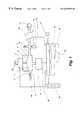
- FIG. 1is a schematic function diagram of an apparatus according to the invention
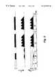
- FIG. 2is a schematic pulse diagram with a non-linear time axis
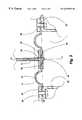
- FIG. 3shows a circular diaphragm of the invention in a mounted state, in a section perpendicular to the plane of the diaphragm B-B and through tIAs centre along axis A—A.
- FIG. 1A preferred embodiment of the apparatus according to the present invention is illustrated schematically in FIG. 1 . It comprises a generally cylindrical chamber 1 for generating pressure pulses by displacement of a flexible circular rubber diaphragm (membrane) 4 forming one base of the chamber 1 , a piston 2 centrally fixed to the essentially non-tensioned (the state of tension being not evident from FIG. 1) diaphragm 4 at its one end and at a ferromagnetic alloy core 22 at its other end, the core 22 being partially inserted into a field coil (solenoid) 3 at the idle (non-pressurised) position.
- the chamber 1has a terminal section 5 provided with a ‘silent’ (sound pressure level ⁇ 20 dB) on/off electromagnetic equalising valve 12 which puts it in communication with the atmosphere when in an open position.
- a ‘silent’sound pressure level ⁇ 20 dB
- a diaphragm 4 of the specific design according to the inventionis shown in FIG. 3 .
- the diaphragm 4consists of a flat circular central portion 32 and a flat annular peripheral portion 33 linked by an annular portion 31 which is approximately semicircular in radial section; it is also possible to use, for instance, a diaphragm having several radially spaced annular portions 31 similar to a circular wave arising at one point at the surface of a liquid.
- the flat portions 32 , 33define the diaphragm plane B—B.
- the semicircular portion 31allows the diaphragm 4 to be displaced along axis A—A out of the diaphragm plane B-B in a forward (towards the chamber) axial direction; displacement is effected against resilient deformation forces in the diaphragm which however are insignificant in relation to resistance against compression by the air enclosed in the chamber.
- the flat circular portion 32is clamped between upper and lower circular disks 35 , 36 .
- the circular portion 32 and the upper and lower disks 35 , 36have central bores for mounting on the piston 2 provided with a roundhead 34 against which they are secured by a circlip 37 disposed in a peripheral slot of the piston 2 .
- the piston 2is fixed to a soft iron or ferromagnetic alloy core 22 (see FIG. 1) partially inserted into the lumen of the field coil 3 (see FIG. 1) at the coil end facing away from the diaphragm.
- the piston 2thus extends into the coil from the other end of the coil.
- the core 22is drawn into the coil 3 , that is, is displaced in the direction of the diaphragm 4 .
- the peripheral diaphragm section 33is clamped between radially extending portions 38 , 30 of the housing and the structure formning the cylindrical wall 39 of the chamber 1 for the generation of pressure pulses, respectively.
- FIGS. 1 and 3Via a flexible plastic tube 10 (of polystyrene, polypropylene or a similar material) the chamber 1 is put into communication with an air volume in the external ear bordering to the tympanic membrane of a patient sealed off by an ear plug 11 .
- the tympanic membraneis penetrated by a microtube which has been applied by surgery; thereby the external and middle ear of the patient are put into communication.
- the pressure in the chamber 1is monitored by a pressure sensor 8 , the signal 20 of which is processed in a control unit comprising a microprocessor 16 and software 14 .
- the treatment dataare stored in the E 2 PROM in form of one or several parameter sets.
- a parameter setcontains all information in regard of pulse amplitude, frequency, pressure increase and decrease rate, etc.
- each parameter setcomprises data for the software controlled safety functions.
- FIG. 2a typical treatment sequence is shown, except for the number of pulse trains being reduced to two for the sake of simplicity.
- the chamber pressure (lowermost section of the diagram), the chamber volume (central section of the diagram) and the mode of the equalising valve 12are set off against time.
- phase Athe pressure sensor 8 is brought to a working temperature, the equilibrating valve 12 is in an open position, and the chamber 1 is at ambient pressure. Then follows a leak test in test phase B. During phase B the valve 12 is kept closed while the pressure is gradually increased to a test pressure p t of about 1 cm H 2 O,and then again decreased to zero. In test phase C a test for openness is carried out. The chamber 1 volume V 0 is varied in the same way as in phase B but with valve 12 in an open position. If the test pressure p t deviates from the expected values the program will stop the apparatus from proceeding to the treatment sequence proper.
- the chamber pressure pis gradually raised to an intermediate pressure p 1 and from there to the maximum pressure p 2 , followed by a decrease to the intermediate pressure p 1 ; the p 1 ⁇ P 2 ⁇ P 1 cycle is repeated trice, followed by lowering the pressure to ambient pressure P 0 .
- a second pulse train(phase F) similar to the one in phase D is generated.
- Thisis followed by a second interval at p 0 (phase G) and 10 to 30 further pulse trains (not shown) with corresponding intervals.
- This first treatment section of equally spaced 12-32 pulse trainsis followed by a rest period of about 25-90 seconds, and second and third treatment sections also spaced by a corresponding rest period. For optimal effect the treatment should be repeated several times a day.
Landscapes
- Health & Medical Sciences (AREA)
- Life Sciences & Earth Sciences (AREA)
- Public Health (AREA)
- Engineering & Computer Science (AREA)
- Veterinary Medicine (AREA)
- Biomedical Technology (AREA)
- Heart & Thoracic Surgery (AREA)
- Animal Behavior & Ethology (AREA)
- General Health & Medical Sciences (AREA)
- Hematology (AREA)
- Anesthesiology (AREA)
- Physics & Mathematics (AREA)
- Acoustics & Sound (AREA)
- Biophysics (AREA)
- Otolaryngology (AREA)
- Psychology (AREA)
- Vascular Medicine (AREA)
- External Artificial Organs (AREA)
- Acyclic And Carbocyclic Compounds In Medicinal Compositions (AREA)
- Massaging Devices (AREA)
- Percussion Or Vibration Massage (AREA)
- Accommodation For Nursing Or Treatment Tables (AREA)
Abstract
Description
Claims (31)
Applications Claiming Priority (3)
| Application Number | Priority Date | Filing Date | Title |
|---|---|---|---|
| SE9802423ASE9802423D0 (en) | 1998-07-06 | 1998-07-06 | Device for the treatment of Meniere's disease and similar ailments |
| SE9802423 | 1998-07-06 | ||
| PCT/SE1999/001168WO2000001346A2 (en) | 1998-07-06 | 1999-06-29 | Apparatus for treatment of meniere's disease and similar conditions |
Publications (1)
| Publication Number | Publication Date |
|---|---|
| US6629938B1true US6629938B1 (en) | 2003-10-07 |
Family
ID=20411981
Family Applications (1)
| Application Number | Title | Priority Date | Filing Date |
|---|---|---|---|
| US09/743,168Expired - LifetimeUS6629938B1 (en) | 1998-07-06 | 1999-06-29 | Apparatus for treatment of ménière's disease and similar conditions |
Country Status (20)
| Country | Link |
|---|---|
| US (1) | US6629938B1 (en) |
| EP (1) | EP1094770B1 (en) |
| JP (1) | JP2002519150A (en) |
| KR (1) | KR20010081987A (en) |
| CN (1) | CN1308513A (en) |
| AT (1) | ATE275906T1 (en) |
| AU (1) | AU736919B2 (en) |
| BR (1) | BR9911921A (en) |
| CA (1) | CA2337076C (en) |
| DE (1) | DE69920229T2 (en) |
| HK (1) | HK1039445A1 (en) |
| HU (1) | HUP0102951A3 (en) |
| IL (1) | IL140634A0 (en) |
| MX (1) | MXPA00012919A (en) |
| NO (1) | NO20010096L (en) |
| NZ (1) | NZ509123A (en) |
| PL (1) | PL345702A1 (en) |
| SE (1) | SE9802423D0 (en) |
| TR (1) | TR200100028T2 (en) |
| WO (1) | WO2000001346A2 (en) |
Cited By (34)
| Publication number | Priority date | Publication date | Assignee | Title |
|---|---|---|---|---|
| US20030220536A1 (en)* | 2002-05-21 | 2003-11-27 | Hissong James B. | Apparatus and methods for directly displacing the partition between the middle ear and inner ear at an infrasonic frequency |
| US20030220585A1 (en)* | 2002-05-21 | 2003-11-27 | Hissong James B. | Apparatus and method for displacing the partition between the middle ear and the inner ear using a manually powered device |
| US20040225178A1 (en)* | 2002-05-21 | 2004-11-11 | Kriewall Timothy J. | Apparatus and methods for treating symptoms of disease and conditions of the ear |
| US20060272650A1 (en)* | 2005-06-07 | 2006-12-07 | Micromedics, Inc. | Middle ear pressure equalizing device with improved pressure control |
| US20060287958A1 (en)* | 2001-05-31 | 2006-12-21 | Laurence Lundblade | Safe application distribution and execution in a wireless environment |
| US20070060948A1 (en)* | 2003-05-19 | 2007-03-15 | Burkhard Franz | Portable hand-operable device for applying pneumatic pressure pulses to an ear canal |
| RU2308931C2 (en)* | 2005-12-12 | 2007-10-27 | Общество с ограниченной ответственностью "Научно Производственная Компания "АЗИМУТ" | Pneumatic massaging apparatus for drum membrane |
| US20090012420A1 (en)* | 2007-07-02 | 2009-01-08 | Micro Audiometrics Corporation | Ear Canal Pressurization Device |
| US7561915B1 (en) | 2004-12-17 | 2009-07-14 | Cardiac Pacemakers, Inc. | MRI system having implantable device safety features |
| US8014867B2 (en) | 2004-12-17 | 2011-09-06 | Cardiac Pacemakers, Inc. | MRI operation modes for implantable medical devices |
| US8032228B2 (en) | 2007-12-06 | 2011-10-04 | Cardiac Pacemakers, Inc. | Method and apparatus for disconnecting the tip electrode during MRI |
| US8086321B2 (en) | 2007-12-06 | 2011-12-27 | Cardiac Pacemakers, Inc. | Selectively connecting the tip electrode during therapy for MRI shielding |
| US8160717B2 (en) | 2008-02-19 | 2012-04-17 | Cardiac Pacemakers, Inc. | Model reference identification and cancellation of magnetically-induced voltages in a gradient magnetic field |
| US8287495B2 (en) | 2009-07-30 | 2012-10-16 | Tandem Diabetes Care, Inc. | Infusion pump system with disposable cartridge having pressure venting and pressure feedback |
| US8311637B2 (en) | 2008-02-11 | 2012-11-13 | Cardiac Pacemakers, Inc. | Magnetic core flux canceling of ferrites in MRI |
| US8408421B2 (en) | 2008-09-16 | 2013-04-02 | Tandem Diabetes Care, Inc. | Flow regulating stopcocks and related methods |
| US8565874B2 (en) | 2009-12-08 | 2013-10-22 | Cardiac Pacemakers, Inc. | Implantable medical device with automatic tachycardia detection and control in MRI environments |
| US8571661B2 (en) | 2008-10-02 | 2013-10-29 | Cardiac Pacemakers, Inc. | Implantable medical device responsive to MRI induced capture threshold changes |
| US8639331B2 (en) | 2009-02-19 | 2014-01-28 | Cardiac Pacemakers, Inc. | Systems and methods for providing arrhythmia therapy in MRI environments |
| US8650937B2 (en) | 2008-09-19 | 2014-02-18 | Tandem Diabetes Care, Inc. | Solute concentration measurement device and related methods |
| US8870791B2 (en) | 2006-03-23 | 2014-10-28 | Michael E. Sabatino | Apparatus for acquiring, processing and transmitting physiological sounds |
| WO2014210457A1 (en)* | 2013-06-28 | 2014-12-31 | Gbs Ventures Llc | External ear canal pressure regulation system |
| US8986253B2 (en) | 2008-01-25 | 2015-03-24 | Tandem Diabetes Care, Inc. | Two chamber pumps and related methods |
| EP3013293A4 (en)* | 2013-06-28 | 2017-05-17 | Gbs Ventures LLC | External ear canal pressure regulation device |
| US9962486B2 (en) | 2013-03-14 | 2018-05-08 | Tandem Diabetes Care, Inc. | System and method for detecting occlusions in an infusion pump |
| US10258736B2 (en) | 2012-05-17 | 2019-04-16 | Tandem Diabetes Care, Inc. | Systems including vial adapter for fluid transfer |
| US10271992B2 (en) | 2013-04-23 | 2019-04-30 | Daiichi Medical Co., Ltd. | Portable device for treating Meniere's disease and similar conditions |
| US10760566B2 (en) | 2016-07-22 | 2020-09-01 | Nocira, Llc | Magnetically driven pressure generator |
| US10959630B1 (en) | 2017-09-27 | 2021-03-30 | Micro Audiometrics Corporation | Dual audiometric probe headset |
| US11071543B2 (en) | 2017-12-15 | 2021-07-27 | Cilag Gmbh International | Surgical end effectors with clamping assemblies configured to increase jaw aperture ranges |
| US11246793B2 (en) | 2017-02-27 | 2022-02-15 | Nocira, Llc | Ear pumps |
| US11272865B1 (en) | 2017-09-27 | 2022-03-15 | Micro Audiometrics Corporation | Audiometric probe including dual pressure transducer air system control |
| US12178966B2 (en) | 2018-06-22 | 2024-12-31 | Nocira, Llc | Systems and methods for treating neurological disorders |
| US12396892B2 (en) | 2013-06-28 | 2025-08-26 | Nocira, Llc | External ear canal pressure regulation device |
Families Citing this family (5)
| Publication number | Priority date | Publication date | Assignee | Title |
|---|---|---|---|---|
| AU2004238090B2 (en)* | 2003-05-19 | 2009-06-04 | Burkhard Franz Pty Ltd | A portable hand-operable device for applying pneumatic pressure pulses to an ear canal |
| CN102510746B (en)* | 2009-07-15 | 2014-08-20 | 阿克拉伦特公司 | Tympanic membrane pressure equalization tube delivery system |
| CN109998518B (en)* | 2019-03-05 | 2020-08-07 | 深圳先进技术研究院 | Diaphragm movement auxiliary device and diaphragm movement auxiliary system |
| GB201908260D0 (en)* | 2019-06-10 | 2019-07-24 | Univ Of Brighton | Method and device for sustance delivery to the inner ear |
| CN110101530A (en)* | 2019-06-15 | 2019-08-09 | 吉林大学 | A device for balancing the internal and external pressure of the ear canal tympanic membrane |
Citations (4)
| Publication number | Priority date | Publication date | Assignee | Title |
|---|---|---|---|---|
| GB190910695A (en) | 1909-05-05 | 1910-01-06 | Gustave Frantz Lyon | Improvements in Harps. |
| WO1983002556A1 (en) | 1982-01-22 | 1983-08-04 | Barbara Densert | An apparatus for influencing the hydrodynamic system in the inner of an ear |
| WO1993008775A1 (en) | 1991-11-08 | 1993-05-13 | Hb Proxima | Air pressure generator |
| WO1997023178A1 (en) | 1995-12-22 | 1997-07-03 | Pascal Medical Ab | Device for affecting the hydrodynamic system of the inner ear |
- 1998
- 1998-07-06SESE9802423Apatent/SE9802423D0/enunknown
- 1999
- 1999-06-29NZNZ509123Apatent/NZ509123A/enunknown
- 1999-06-29KRKR1020017000061Apatent/KR20010081987A/ennot_activeWithdrawn
- 1999-06-29MXMXPA00012919Apatent/MXPA00012919A/enunknown
- 1999-06-29CACA002337076Apatent/CA2337076C/ennot_activeExpired - Lifetime
- 1999-06-29CNCN99808261Apatent/CN1308513A/enactivePending
- 1999-06-29EPEP99933406Apatent/EP1094770B1/ennot_activeExpired - Lifetime
- 1999-06-29DEDE69920229Tpatent/DE69920229T2/ennot_activeExpired - Lifetime
- 1999-06-29PLPL99345702Apatent/PL345702A1/enunknown
- 1999-06-29USUS09/743,168patent/US6629938B1/ennot_activeExpired - Lifetime
- 1999-06-29AUAU49467/99Apatent/AU736919B2/ennot_activeExpired
- 1999-06-29TRTR2001/00028Tpatent/TR200100028T2/enunknown
- 1999-06-29JPJP2000557794Apatent/JP2002519150A/enactivePending
- 1999-06-29ILIL14063499Apatent/IL140634A0/enunknown
- 1999-06-29BRBR9911921-8Apatent/BR9911921A/ennot_activeApplication Discontinuation
- 1999-06-29ATAT99933406Tpatent/ATE275906T1/ennot_activeIP Right Cessation
- 1999-06-29WOPCT/SE1999/001168patent/WO2000001346A2/ennot_activeApplication Discontinuation
- 1999-06-29HKHK02100997.1Apatent/HK1039445A1/enunknown
- 1999-06-29HUHU0102951Apatent/HUP0102951A3/enunknown
- 2001
- 2001-01-05NONO20010096Apatent/NO20010096L/ennot_activeApplication Discontinuation
Patent Citations (5)
| Publication number | Priority date | Publication date | Assignee | Title |
|---|---|---|---|---|
| GB190910695A (en) | 1909-05-05 | 1910-01-06 | Gustave Frantz Lyon | Improvements in Harps. |
| WO1983002556A1 (en) | 1982-01-22 | 1983-08-04 | Barbara Densert | An apparatus for influencing the hydrodynamic system in the inner of an ear |
| WO1993008775A1 (en) | 1991-11-08 | 1993-05-13 | Hb Proxima | Air pressure generator |
| WO1997023178A1 (en) | 1995-12-22 | 1997-07-03 | Pascal Medical Ab | Device for affecting the hydrodynamic system of the inner ear |
| US6159171A (en)* | 1995-12-22 | 2000-12-12 | Pascal Medical Ab | Device for affecting the hydrodynamic system of the inner ear |
Non-Patent Citations (1)
| Title |
|---|
| Preprint from Acta Otolaryngol (Stockh) 1986 "Transmission of Square Wave Pressure Pulses through the Perilymphatic Fluid in Cats", by B. Densert et al., pp. 1-8. |
Cited By (72)
| Publication number | Priority date | Publication date | Assignee | Title |
|---|---|---|---|---|
| US20060287958A1 (en)* | 2001-05-31 | 2006-12-21 | Laurence Lundblade | Safe application distribution and execution in a wireless environment |
| US7179238B2 (en) | 2002-05-21 | 2007-02-20 | Medtronic Xomed, Inc. | Apparatus and methods for directly displacing the partition between the middle ear and inner ear at an infrasonic frequency |
| US20030220536A1 (en)* | 2002-05-21 | 2003-11-27 | Hissong James B. | Apparatus and methods for directly displacing the partition between the middle ear and inner ear at an infrasonic frequency |
| US6958043B2 (en) | 2002-05-21 | 2005-10-25 | Medtronic Xomed, Inc. | Apparatus and method for displacing the partition between the middle ear and the inner ear using a manually powered device |
| US20040225178A1 (en)* | 2002-05-21 | 2004-11-11 | Kriewall Timothy J. | Apparatus and methods for treating symptoms of disease and conditions of the ear |
| US20030220585A1 (en)* | 2002-05-21 | 2003-11-27 | Hissong James B. | Apparatus and method for displacing the partition between the middle ear and the inner ear using a manually powered device |
| US20070060948A1 (en)* | 2003-05-19 | 2007-03-15 | Burkhard Franz | Portable hand-operable device for applying pneumatic pressure pulses to an ear canal |
| US7766858B2 (en) | 2003-05-19 | 2010-08-03 | Burkhard Franz Pty. Ltd. | Portable hand-operable device for applying pneumatic pressure pulses to an ear canal |
| US8543207B2 (en) | 2004-12-17 | 2013-09-24 | Cardiac Pacemakers, Inc. | MRI operation modes for implantable medical devices |
| US8886317B2 (en) | 2004-12-17 | 2014-11-11 | Cardiac Pacemakers, Inc. | MRI operation modes for implantable medical devices |
| US7561915B1 (en) | 2004-12-17 | 2009-07-14 | Cardiac Pacemakers, Inc. | MRI system having implantable device safety features |
| US8014867B2 (en) | 2004-12-17 | 2011-09-06 | Cardiac Pacemakers, Inc. | MRI operation modes for implantable medical devices |
| US20060272650A1 (en)* | 2005-06-07 | 2006-12-07 | Micromedics, Inc. | Middle ear pressure equalizing device with improved pressure control |
| US7484531B2 (en)* | 2005-06-07 | 2009-02-03 | Micromedics, Inc. | Middle ear pressure equalizing device with improved pressure control |
| US20090126738A1 (en)* | 2005-06-07 | 2009-05-21 | Micromedics, Inc. | Middle Ear Pressure Equalizing Device With Improved Pressure Control |
| RU2308931C2 (en)* | 2005-12-12 | 2007-10-27 | Общество с ограниченной ответственностью "Научно Производственная Компания "АЗИМУТ" | Pneumatic massaging apparatus for drum membrane |
| US8920343B2 (en) | 2006-03-23 | 2014-12-30 | Michael Edward Sabatino | Apparatus for acquiring and processing of physiological auditory signals |
| US11357471B2 (en) | 2006-03-23 | 2022-06-14 | Michael E. Sabatino | Acquiring and processing acoustic energy emitted by at least one organ in a biological system |
| US8870791B2 (en) | 2006-03-23 | 2014-10-28 | Michael E. Sabatino | Apparatus for acquiring, processing and transmitting physiological sounds |
| US8398562B2 (en)* | 2007-07-02 | 2013-03-19 | Micro Audiometrics Corporation | Ear canal pressurization device |
| US20090012420A1 (en)* | 2007-07-02 | 2009-01-08 | Micro Audiometrics Corporation | Ear Canal Pressurization Device |
| US8897875B2 (en) | 2007-12-06 | 2014-11-25 | Cardiac Pacemakers, Inc. | Selectively connecting the tip electrode during therapy for MRI shielding |
| US8086321B2 (en) | 2007-12-06 | 2011-12-27 | Cardiac Pacemakers, Inc. | Selectively connecting the tip electrode during therapy for MRI shielding |
| US8032228B2 (en) | 2007-12-06 | 2011-10-04 | Cardiac Pacemakers, Inc. | Method and apparatus for disconnecting the tip electrode during MRI |
| US8554335B2 (en) | 2007-12-06 | 2013-10-08 | Cardiac Pacemakers, Inc. | Method and apparatus for disconnecting the tip electrode during MRI |
| US8986253B2 (en) | 2008-01-25 | 2015-03-24 | Tandem Diabetes Care, Inc. | Two chamber pumps and related methods |
| US8311637B2 (en) | 2008-02-11 | 2012-11-13 | Cardiac Pacemakers, Inc. | Magnetic core flux canceling of ferrites in MRI |
| US8160717B2 (en) | 2008-02-19 | 2012-04-17 | Cardiac Pacemakers, Inc. | Model reference identification and cancellation of magnetically-induced voltages in a gradient magnetic field |
| US8448824B2 (en) | 2008-09-16 | 2013-05-28 | Tandem Diabetes Care, Inc. | Slideable flow metering devices and related methods |
| US8408421B2 (en) | 2008-09-16 | 2013-04-02 | Tandem Diabetes Care, Inc. | Flow regulating stopcocks and related methods |
| US8650937B2 (en) | 2008-09-19 | 2014-02-18 | Tandem Diabetes Care, Inc. | Solute concentration measurement device and related methods |
| US8571661B2 (en) | 2008-10-02 | 2013-10-29 | Cardiac Pacemakers, Inc. | Implantable medical device responsive to MRI induced capture threshold changes |
| US9561378B2 (en) | 2008-10-02 | 2017-02-07 | Cardiac Pacemakers, Inc. | Implantable medical device responsive to MRI induced capture threshold changes |
| US8639331B2 (en) | 2009-02-19 | 2014-01-28 | Cardiac Pacemakers, Inc. | Systems and methods for providing arrhythmia therapy in MRI environments |
| US8977356B2 (en) | 2009-02-19 | 2015-03-10 | Cardiac Pacemakers, Inc. | Systems and methods for providing arrhythmia therapy in MRI environments |
| US8926561B2 (en) | 2009-07-30 | 2015-01-06 | Tandem Diabetes Care, Inc. | Infusion pump system with disposable cartridge having pressure venting and pressure feedback |
| US8298184B2 (en) | 2009-07-30 | 2012-10-30 | Tandem Diabetes Care, Inc. | Infusion pump system with disposable cartridge having pressure venting and pressure feedback |
| US8758323B2 (en) | 2009-07-30 | 2014-06-24 | Tandem Diabetes Care, Inc. | Infusion pump system with disposable cartridge having pressure venting and pressure feedback |
| US11285263B2 (en) | 2009-07-30 | 2022-03-29 | Tandem Diabetes Care, Inc. | Infusion pump systems and methods |
| US12144964B2 (en) | 2009-07-30 | 2024-11-19 | Tandem Diabetes Care, Inc | Infusion pump system with disposable cartridge having pressure venting and pressure feedback |
| US9211377B2 (en) | 2009-07-30 | 2015-12-15 | Tandem Diabetes Care, Inc. | Infusion pump system with disposable cartridge having pressure venting and pressure feedback |
| US8287495B2 (en) | 2009-07-30 | 2012-10-16 | Tandem Diabetes Care, Inc. | Infusion pump system with disposable cartridge having pressure venting and pressure feedback |
| US11135362B2 (en) | 2009-07-30 | 2021-10-05 | Tandem Diabetes Care, Inc. | Infusion pump systems and methods |
| US12042627B2 (en) | 2009-07-30 | 2024-07-23 | Tandem Diabetes Care, Inc. | Infusion pump systems and methods |
| US9381371B2 (en) | 2009-12-08 | 2016-07-05 | Cardiac Pacemakers, Inc. | Implantable medical device with automatic tachycardia detection and control in MRI environments |
| US8565874B2 (en) | 2009-12-08 | 2013-10-22 | Cardiac Pacemakers, Inc. | Implantable medical device with automatic tachycardia detection and control in MRI environments |
| US10258736B2 (en) | 2012-05-17 | 2019-04-16 | Tandem Diabetes Care, Inc. | Systems including vial adapter for fluid transfer |
| US9962486B2 (en) | 2013-03-14 | 2018-05-08 | Tandem Diabetes Care, Inc. | System and method for detecting occlusions in an infusion pump |
| US10271992B2 (en) | 2013-04-23 | 2019-04-30 | Daiichi Medical Co., Ltd. | Portable device for treating Meniere's disease and similar conditions |
| EP4162917A3 (en)* | 2013-06-28 | 2023-07-19 | Nocira, LLC | External ear canal pressure regulation system |
| US10251790B2 (en) | 2013-06-28 | 2019-04-09 | Nocira, Llc | Method for external ear canal pressure regulation to alleviate disorder symptoms |
| US12419786B2 (en) | 2013-06-28 | 2025-09-23 | Nocira, Llc | External ear canal pressure regulation system |
| US10772766B2 (en) | 2013-06-28 | 2020-09-15 | Nocira, Llc | Method for external ear canal pressure regulation to alleviate disorder symptoms |
| US12396892B2 (en) | 2013-06-28 | 2025-08-26 | Nocira, Llc | External ear canal pressure regulation device |
| US9039639B2 (en) | 2013-06-28 | 2015-05-26 | Gbs Ventures Llc | External ear canal pressure regulation system |
| US11090194B2 (en) | 2013-06-28 | 2021-08-17 | Nocira, Llc | External ear canal pressure regulation device |
| US11096828B2 (en) | 2013-06-28 | 2021-08-24 | Nocira, Llc | System for alleviating symptoms of a neurological disorder |
| US10278868B2 (en) | 2013-06-28 | 2019-05-07 | Nocira, Llc | External ear canal pressure regulation system |
| US12102506B2 (en) | 2013-06-28 | 2024-10-01 | Nocira, Llc | Method for external ear canal pressure regulation to alleviate disorder symptoms |
| EP3013293A4 (en)* | 2013-06-28 | 2017-05-17 | Gbs Ventures LLC | External ear canal pressure regulation device |
| AU2018203016B2 (en)* | 2013-06-28 | 2020-06-04 | Nocira, Llc | External ear canal pressure regulation system |
| US10076464B2 (en) | 2013-06-28 | 2018-09-18 | Nocira, Llc | External ear canal pressure regulation system |
| CN114712084A (en)* | 2013-06-28 | 2022-07-08 | 诺斯莱公司 | External auditory canal pressure adjusting device |
| WO2014210457A1 (en)* | 2013-06-28 | 2014-12-31 | Gbs Ventures Llc | External ear canal pressure regulation system |
| US11859606B2 (en) | 2016-07-22 | 2024-01-02 | Nocira, Llc | Magnetically driven pressure generator |
| US10760566B2 (en) | 2016-07-22 | 2020-09-01 | Nocira, Llc | Magnetically driven pressure generator |
| US12016816B2 (en) | 2017-02-27 | 2024-06-25 | Nocira, Llc | Ear pumps |
| US11246793B2 (en) | 2017-02-27 | 2022-02-15 | Nocira, Llc | Ear pumps |
| US11272865B1 (en) | 2017-09-27 | 2022-03-15 | Micro Audiometrics Corporation | Audiometric probe including dual pressure transducer air system control |
| US10959630B1 (en) | 2017-09-27 | 2021-03-30 | Micro Audiometrics Corporation | Dual audiometric probe headset |
| US11071543B2 (en) | 2017-12-15 | 2021-07-27 | Cilag Gmbh International | Surgical end effectors with clamping assemblies configured to increase jaw aperture ranges |
| US12178966B2 (en) | 2018-06-22 | 2024-12-31 | Nocira, Llc | Systems and methods for treating neurological disorders |
Also Published As
| Publication number | Publication date |
|---|---|
| SE9802423D0 (en) | 1998-07-06 |
| WO2000001346A3 (en) | 2000-03-30 |
| NO20010096L (en) | 2001-03-05 |
| JP2002519150A (en) | 2002-07-02 |
| EP1094770A2 (en) | 2001-05-02 |
| HUP0102951A3 (en) | 2002-02-28 |
| DE69920229T2 (en) | 2005-09-22 |
| NZ509123A (en) | 2002-08-28 |
| WO2000001346A2 (en) | 2000-01-13 |
| AU4946799A (en) | 2000-01-24 |
| IL140634A0 (en) | 2002-02-10 |
| EP1094770B1 (en) | 2004-09-15 |
| HK1039445A1 (en) | 2002-04-26 |
| TR200100028T2 (en) | 2001-05-21 |
| ATE275906T1 (en) | 2004-10-15 |
| CN1308513A (en) | 2001-08-15 |
| CA2337076A1 (en) | 2000-01-13 |
| BR9911921A (en) | 2001-09-25 |
| NO20010096D0 (en) | 2001-01-05 |
| AU736919B2 (en) | 2001-08-09 |
| CA2337076C (en) | 2006-12-12 |
| KR20010081987A (en) | 2001-08-29 |
| HUP0102951A2 (en) | 2001-12-28 |
| MXPA00012919A (en) | 2002-04-10 |
| DE69920229D1 (en) | 2004-10-21 |
| PL345702A1 (en) | 2002-01-02 |
Similar Documents
| Publication | Publication Date | Title |
|---|---|---|
| US6629938B1 (en) | Apparatus for treatment of ménière's disease and similar conditions | |
| US7179238B2 (en) | Apparatus and methods for directly displacing the partition between the middle ear and inner ear at an infrasonic frequency | |
| US6629986B1 (en) | Apparatus and method for performing opthalmic procedures | |
| US20180125748A1 (en) | Devices, Mediums, Systems And Methods For Facilitating Female Sexual Arousal | |
| US6159171A (en) | Device for affecting the hydrodynamic system of the inner ear | |
| US20090131742A1 (en) | Round window driving transducer for easy implantation and implantable hearing device having the same | |
| EP3684311B1 (en) | Trans middle ear-inner ear fluid flow implementations | |
| WO2000001331A2 (en) | Method of treating meniere's disease and corresponding apparatus | |
| WO2000078371A1 (en) | An apparatus and method for performing ophthalmic procedures | |
| JP2019080911A (en) | Micro pump | |
| Bae et al. | In vitro experiment of the pressure regulating valve for a glaucoma implant | |
| US20240033405A1 (en) | Vibratory waveform for breast pump | |
| US20240033406A1 (en) | Breast pump | |
| CZ200124A3 (en) | Apparatus for treating Menier s disease and the like states | |
| JP2621321B2 (en) | Fluid pressure regulating valve device | |
| JP2004097295A (en) | Sphincter replacement device | |
| CN117651573A (en) | Wireless phase transition implantable pump | |
| HK1024159B (en) | Device for affecting the hydrodynamic system of the inner ear |
Legal Events
| Date | Code | Title | Description |
|---|---|---|---|
| AS | Assignment | Owner name:PASCAL MEDICAL AB, SWEDEN Free format text:ASSIGNMENT OF ASSIGNORS INTEREST;ASSIGNORS:ENGVALL, DANIEL;NILSSON, ANDERS;REEL/FRAME:011725/0430 Effective date:20010111 | |
| AS | Assignment | Owner name:MEDTRONIC, INC., MINNESOTA Free format text:ASSIGNMENT OF ASSIGNORS INTEREST;ASSIGNOR:PASCAL MEDICAL AB;REEL/FRAME:014368/0810 Effective date:20011007 | |
| STCF | Information on status: patent grant | Free format text:PATENTED CASE | |
| FEPP | Fee payment procedure | Free format text:PAT HOLDER NO LONGER CLAIMS SMALL ENTITY STATUS, ENTITY STATUS SET TO UNDISCOUNTED (ORIGINAL EVENT CODE: STOL); ENTITY STATUS OF PATENT OWNER: LARGE ENTITY | |
| REFU | Refund | Free format text:REFUND - SURCHARGE, PETITION TO ACCEPT PYMT AFTER EXP, UNINTENTIONAL (ORIGINAL EVENT CODE: R2551); ENTITY STATUS OF PATENT OWNER: LARGE ENTITY | |
| FPAY | Fee payment | Year of fee payment:4 | |
| FPAY | Fee payment | Year of fee payment:8 | |
| FPAY | Fee payment | Year of fee payment:12 | |
| AS | Assignment | Owner name:MENIETT AG, SWITZERLAND Free format text:ASSIGNMENT OF ASSIGNORS INTEREST;ASSIGNOR:MEDTRONIC, INC.;REEL/FRAME:041755/0503 Effective date:20151104 | |
| AS | Assignment | Owner name:LINA MEDICAL APS, DENMARK Free format text:ASSIGNMENT OF ASSIGNORS INTEREST;ASSIGNOR:MENIETT AG;REEL/FRAME:042440/0133 Effective date:20170515 |