US6629782B2 - Tuned fiber optic connector and method - Google Patents
Tuned fiber optic connector and methodDownload PDFInfo
- Publication number
- US6629782B2 US6629782B2US10/067,134US6713402AUS6629782B2US 6629782 B2US6629782 B2US 6629782B2US 6713402 AUS6713402 AUS 6713402AUS 6629782 B2US6629782 B2US 6629782B2
- Authority
- US
- United States
- Prior art keywords
- hub
- ferrule
- housing
- connector
- rear housing
- Prior art date
- Legal status (The legal status is an assumption and is not a legal conclusion. Google has not performed a legal analysis and makes no representation as to the accuracy of the status listed.)
- Expired - Lifetime
Links
Images


Classifications
- G—PHYSICS
- G02—OPTICS
- G02B—OPTICAL ELEMENTS, SYSTEMS OR APPARATUS
- G02B6/00—Light guides; Structural details of arrangements comprising light guides and other optical elements, e.g. couplings
- G02B6/24—Coupling light guides
- G02B6/36—Mechanical coupling means
- G02B6/38—Mechanical coupling means having fibre to fibre mating means
- G02B6/3807—Dismountable connectors, i.e. comprising plugs
- G02B6/3833—Details of mounting fibres in ferrules; Assembly methods; Manufacture
- G02B6/3834—Means for centering or aligning the light guide within the ferrule
- G02B6/3843—Means for centering or aligning the light guide within the ferrule with auxiliary facilities for movably aligning or adjusting the fibre within its ferrule, e.g. measuring position or eccentricity
- G—PHYSICS
- G02—OPTICS
- G02B—OPTICAL ELEMENTS, SYSTEMS OR APPARATUS
- G02B6/00—Light guides; Structural details of arrangements comprising light guides and other optical elements, e.g. couplings
- G02B6/24—Coupling light guides
- G02B6/36—Mechanical coupling means
- G02B6/38—Mechanical coupling means having fibre to fibre mating means
- G02B6/3807—Dismountable connectors, i.e. comprising plugs
- G02B6/3869—Mounting ferrules to connector body, i.e. plugs
- G02B6/3871—Ferrule rotatable with respect to plug body, e.g. for setting rotational position ; Fixation of ferrules after rotation
- G—PHYSICS
- G02—OPTICS
- G02B—OPTICAL ELEMENTS, SYSTEMS OR APPARATUS
- G02B6/00—Light guides; Structural details of arrangements comprising light guides and other optical elements, e.g. couplings
- G02B6/24—Coupling light guides
- G02B6/36—Mechanical coupling means
- G02B6/38—Mechanical coupling means having fibre to fibre mating means
- G02B6/3807—Dismountable connectors, i.e. comprising plugs
- G02B6/389—Dismountable connectors, i.e. comprising plugs characterised by the method of fastening connecting plugs and sockets, e.g. screw- or nut-lock, snap-in, bayonet type
- G02B6/3893—Push-pull type, e.g. snap-in, push-on
Definitions
- the present inventionrelates to tunable fiber optic connectors for use in an optical fiber signal transmission system, and to methods for assembling such fiber optic connectors.
- Fiber optic cablesare used in the telecommunication industry to transmit light signals in high-speed data and communication systems.
- a standard fiber optic cableincludes a fiber with an inner light transmitting optical core. Surrounding the fiber is an outer protective casing.
- a fiberterminates at a fiber optic connector.
- Connectorsare frequently used to non-permanently connect and disconnect optical elements in a fiber optic transmission system.
- Other types of connectorsinclude ST and D4-type connectors.
- a typical SC fiber optic connectorincludes a housing having a front end positioned opposite from a rear end.
- the front end of the SC connector housingis commonly configured to be inserted within an adapter.
- An example adapteris shown in U.S. Pat. No. 5,317,663, assigned to ADC Telecommunications, Inc.
- the SC connectortypically further includes a ferrule that is positioned within the front and rear ends of the housing, and adjacent the front end. The ferrule is axially moveable relative to the housing, and is spring biased toward the front of the connector.
- the fiber optic cablehas an end that is stripped. The stripped end includes a bare fiber that extends into the connector and through the ferrule.
- a connectorsuch as the connector described above, is mated to another connector within an adapter like the adapter of U.S. Pat. No. 5,317,663.
- a first connectoris received within the front portion of the adapter, and a second fiber is received within the rear portion of the adapter.
- the ferrulesand hence the fibers internal to the ferrule contact or are in close proximity to each other to provide for signal transmission between the fibers.
- Another connector and mating adapteris shown in U.S. Pat. No. 6,142,676, assigned to ADC Telecommunications, Inc.
- Signal losses within a systemoften occur within the connection between two optical fiber cores. Due to manufacturing tolerances of the ferrule outer diameter to inner diameter concentricity, ferrule inner diameter hole size and fiber outer diameter, and fiber core to fiber outer diameter concentricity, when the fiber is inserted into the ferrule the core of a fiber may not and typically does not end up perfectly centered relative to the ferrule outer diameter. If one or both of the fibers are off center, when they are connected within an adapter, the fibers will not be aligned and thus there will be a signal loss when the signal is transmitted between the two fibers. It is therefore desirable to tune a connector to minimize this signal loss. Tuning can be accomplished by measuring signal characteristics through the connector and/or examining physical properties of the connector, and then determining the optimal position of the ferrule and fiber in the connector.
- the present inventionconcerns tunable fiber optic connectors including a spring biased ferrule and hub assembly within the connector.
- Tuningcan be accomplished by partially assembling the connector and pressing the ferrule back into the connector so that an anti-rotation portion of the hub clears an anti-rotation seat of the connector. In this position, the ferrule can be rotated about a connector axis to the desired rotational alignment that minimizes signal loss. The ferrule can then be released, allowing the anti-rotation portion of the hub to re-engage the anti-rotation seat, thereby preventing further rotation that may cause the connector to become un-tuned. The connector is then fully assembled so that the ferrule cannot be inadvertently pushed back into the connector and turned.
- a fiber optic connectorincluding an optical fiber, a ferrule mounted to the optical fiber, a hub retainably engaging the ferrule, wherein the hub includes an elongated rear portion coupled to an anti-rotation portion, a rear housing having an external surface and a bore for receiving the optical fiber, a front housing having an internal surface for receiving and engaging the external surface of the rear housing, having an anti-rotation seat configured to engage the anti-rotation portion of the hub, and defining a cavity coupled to the anti-rotation seat; and a spring captured between the anti-rotation portion of the hub and the rear housing to bias the anti-rotation portion of the hub into the anti-rotation seat of the front housing.
- a length of the elongated rear portion of the hubis sized so that: (1) the anti-rotation portion of the hub can be pushed completely into the cavity and rotated to tune the connector when the rear housing is partially inserted into the front housing; and (2) an end of the elongated rear portion of the hub abuts the rear housing so that the anti-rotation portion of the hub cannot be completely pushed back into the cavity and rotated when the rear housing is completely engaged with the front housing.
- a fiber optic connectorcomprising a ferrule and hub assembly including an inner bore defining a connector axis and sized for receipt of an optical fiber, a front end defining an end face, an opposite rear end, and an anti-rotation portion disposed between the front and rear ends, a front housing having an anti-rotation seat engageable with the anti-rotation portion of the ferrule and hub assembly in a plurality of positions about the connector axis, a rear housing mountable to the front housing in a first, partially assembled position and a second, fully assembled position, the partially assembled and fully assembled positions defining different relative positions along the connector axis, the front and rear housings defining a chamber for receipt of the ferrule and hub assembly, and a spring within the chamber for biasing the ferrule and hub assembly away from the rear housing.
- the ferrule and hub assemblyis moveable within the chamber along the connector axis against the spring bias when the front and rear housings are in the partially assembled position so that the anti-rotation seat is disengaged from the anti-rotation portion, wherein the ferrule and hub assembly can be rotated about the connector axis relative to the front and rear housings, and the ferrule and hub assembly, when the front and rear housings are in the fully assembled position, engages the rear housing when moved within the chamber along the connector axis, thereby preventing the anti-rotation seat from disengaging from the anti-rotation portion.
- Yet another aspect of the inventionrelates to a fiber optic connector including an optical fiber, a ferrule mounted to the optical fiber, a hub retainably engaging the ferrule, wherein the hub includes an cylindrical rear portion coupled to an anti-rotation portion, a rear housing having an engagement surface and a bore for receiving the optical fiber, a front housing having an engagement surface for receiving and engaging the engagement surface of the rear housing and having an anti-rotation seat configured to engage the anti-rotation portion of the hub; and a spring captured between the anti-rotation portion of the hub and the rear housing to bias the anti-rotation portion of the hub into the anti-rotation seat of the front housing.
- the front and rear housingstogether define a cavity having a longitudinal length extending along a connector axis so that: (1) when the rear housing is partially inserted into the front housing, the longitudinal length of the cavity is of sufficient length to allow the anti-rotation portion of the hub to be pushed completely into the cavity and rotated to tune the connector; and (2) when the rear housing is fully inserted into the front housing, the longitudinal length of the cavity is not of sufficient length to allow the anti-rotation portion of the hub to be pushed completely into the cavity and rotated to tune the connector.
- Another aspect of the inventionrelates to a method for tuning a fiber optic connector including steps of: providing a ferrule with a hub retainably engaging the ferrule, the hub including an anti-rotation portion; providing a front housing including a bore with an engagement surface, an anti-rotation seat, and defining a cavity; providing a rear housing including a bore with an engagement surface; inserting the bore of the rear housing partially into the bore of the front housing; pushing the hub into the cavity so that the anti-rotation portion clears the anti-rotation seat of the front housing; rotating the ferrule and the hub to tune the connector; releasing the hub so that the anti-rotation portion re-engages the anti-rotation seat of the front housing; and pushing the rear housing further into the front housing until the rear and front housing are fully engaged.
- Another aspect of the inventionrelates to a method for tuning a fiber optic connector including steps of: providing a fiber held by a ferrule with a hub retainably engaging the ferrule, the hub extending for a length and including a rear end, the connector including front and rear housings engageable with one another, wherein a length of the hub is such that the rear end abuts the rear housing of the connector when the rear housing is fully engaged with the front housing and the ferrule and hub are pushed back towards the rear housing; inserting the rear housing partially into the front housing; pushing the ferrule back towards the rear housing; rotating the ferrule and hub to tune the connector; and pushing the rear housing further into the front housing until the rear housing completely engages the front housing and thereby prevents further rotation of the ferrule and the hub.
- Yet another aspect of the inventionrelates to a method for tuning a fiber optic connector, the method comprising steps of: providing a fiber held by a ferrule with a hub retainably engaging the ferrule, the hub extending for a length and including a rear end, the connector including front and rear housings engageable with one another, wherein a length of the hub is such that the rear end abuts the rear housing of the connector when the rear housing is fully engaged with the front housing and the ferrule and hub are pushed back towards the rear housing; inserting the rear housing partially into the front housing; measuring alignment of the fiber in the ferrule; and pushing the rear housing further into the front housing until the rear housing completely engages the front housing and thereby prevents further rotation of the ferrule and the hub.
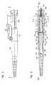
- FIG. 1is an exploded view of an example embodiment of a fiber optic connector made in accordance with the present invention.
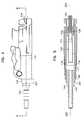
- FIG. 2is a side view of the connector of FIG. 1 in a fully assembled state with the front cover removed.
- FIG. 3is a cross-sectional view taken along line A—A of the connector shown in FIG. 2 .
- FIG. 4is a side view of the connector of FIG. 1 in a partially assembled state:
- FIG. 5is a cross-sectional view taken along line B—B of the connector shown in FIG. 4 .
- FIG. 6is a side view of the connector of FIG. 1 in a partially assembled state with a ferrule and hub of the connector pushed towards a rear of the connector.
- FIG. 7is a cross-sectional view taken along line C—C of the connector shown in FIG. 6 .
- FIG. 8is a side view of the connector of FIG. 1 in a fully assembled state with the ferrule and hub pushed back towards a rear of the connector.
- FIG. 9is a cross-sectional view taken along line D—D of the connector shown in FIG. 8 .
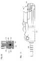
- FIG. 10is a cross-sectional view taken along line E—E of the connector shown in FIG. 3 .
- FIG. 11is a side view of the connector with the front cover pivoted closed.
- FIG. 1is an exploded view of an example connector 100 illustrating components made in accordance with the present invention.
- the connector 100includes a front housing 110 , a rear housing 140 , and a boot 150 with a bore 152 .
- a hub/ferrule assembly 120with a hub 122 and a ferrule 124 .
- the hub 122includes an anti-rotation portion 128 and an elongated cylindrical rear portion 123 .
- the hub 122is connected to the ferrule 124 , such as with adhesive or with an interference fit.
- a spring 130is also provided.
- a fiber optic cable 101is shown including a fiber 102 and a jacket 103 .
- the cable 101is of the type without reinforcing strength members.
- the connector 100is shown in a fully assembled state.
- the front housing 110 of the connector 100extends along a longitudinal axis 200 and defines an anti-rotation seat 112 and a cavity 114 .
- the ferrule 124extends through a front bore 116 of the front housing 110 and includes a passage 166 .
- the anti-rotation portion 128 of the hub 122is slidingly engaged along the longitudinal axis 200 in the anti-rotation seat 112 .
- the anti-rotation portion 128is shaped in an octagonal configuration (see FIG. 10) and the anti-rotation seat 112 defines a seat of a complementary geometry.
- the anti-rotation portion 128 and the anti-rotation seat 112allow for sliding along the longitudinal axis 200 , but prevent relative rotation. Other mating shapes and configurations are also possible.
- the elongated cylindrical rear portion 123 of the hub 122extends into the cavity 114 of the front housing 110 .
- the hub 122includes a passage 119 extending along the longitudinal axis 200 .
- the spring 130surrounds the elongated cylindrical rear portion 123 of the hub 122 .
- the spring 130is captured between the anti-rotation portion 128 and a surface 146 of the rear housing 140 .
- the spring 130functions to bias the anti-rotation portion 128 of the hub 122 into the anti-rotation seat 112 of the front housing 110 . Because the ferrule 124 is connected to the hub 122 , the spring 130 also functions to bias the ferrule 124 in a forward direction through the front bore 116 .
- An outer surface 143 of the rear housing 140is held engagingly in a rear bore 117 of the front housing 110 .
- the rear housing 140In the fully engaged position as shown, the rear housing 140 is seated against notches 118 positioned in the rear bore 117 .
- the rear housing 140includes a passage 147 .
- a rear portion 145 of the rear housing 140extends along the longitudinal axis 200 into the bore 152 of the boot 150 .
- Arms 151 of the boot 150extend over tabs 144 formed by the rear portion 145 to hold the rear housing 140 to the boot 150 .
- a passage 152 extending through the boot 150is coaxially aligned with passage 147 of the rear housing 140 and passage 119 of the hub 122 .
- the passage 119in turn, is coaxially aligned with the passage 166 of the ferrule 124 and is sized to receive a bare fiber of a fiber optic cable.
- the rear housing 140is held to front housing 110 with an interference fit.
- FIGS. 2 and 3show the final assembled positions of the front and rear housings 110 and 140 .
- An interference fitalso is present when the front and rear housings 110 and 140 are partially inserted, as will be described below.
- the cable 101not shown in FIGS. 2 and 3, is extended through the passages 152 and 147 , and the fiber 102 is extended through passages 119 and 166 and is glued to the ferrule 124 .
- the jacket 103extends through passage 119 and can abut the ferrule 124 .
- the jacket 103is glued to the hub 122 .
- the connector 100includes a spring-biased pivoting front cover 105 which biases the cover toward the closed position (as shown in FIG. 11) or the open position as the cover is moved in a direction F. Further details of the exterior features of the connector 100 and mating adapter are shown and described in U.S. Pat. No. 6,142,676, the disclosure of which is hereby incorporated by reference.
- a latch 107latches the connector 100 to the adapter.
- Guides 108engage rails on the adapter to guide the connector 100 into the adapter.
- the connector 100can be assembled and tuned as follows.
- the hub 122 and ferrule 124are inserted into the front housing so that the anti-rotation portion 128 of the hub 122 sits in the anti-rotation seat 112 of the front housing 110 .
- the spring 130has been removed for clarity (as well as the boot 150 ), it should be understood that the spring 130 surrounds the elongated cylindrical rear portion 123 of the hub 122 .
- the rear housing 140is then partially slid into the front housing 110 so that a portion 201 of the outer surface 143 of the rear housing 140 at least partially remains outside of the front housing 110 and the rear housing 140 remains spaced apart from the notches 118 .
- the spring 130is captured between the anti-rotation portion 128 of the hub 122 and the surface 146 of the rear housing 140 , and the spring biases the anti-rotation portion 128 of the hub 122 into the anti-rotation seat of the housing 110 , thereby preventing rotation of the hub 122 and the attached ferrule 124 .
- a sufficient interference fitexists between the front and rear housings 110 and 140 so that the two parts are held together containing the spring 130 , the hub 122 , and the ferrule 124 .
- the front and rear housings 110 and 140are pressed together in any convenient manner, such as with a press or clamping tool.
- the ferrule 124 and the hub 122can be pushed back against the biasing force of the spring 130 along the longitudinal axis 200 towards the rear housing 140 so that the anti-rotation portion 128 of the hub 122 enters the cavity 114 and completely clears the anti-rotation seat 112 .
- the ferrule 124 and the hub 122can be rotated about the longitudinal axis 200 to tune the connector 100 as desired. Tuning can be by any method useful to determine the desired rotational position of the ferrule 124 in the connector 100 . Once the ferrule 124 has been rotated to the desired rotational alignment, the ferrule 124 can be released and the spring 130 can once again bias the anti-rotation portion 128 of the hub 122 into the anti-rotation seat 112 of the front housing 110 (similar to the configuration illustrated in FIGS. 4 and 5 ), thereby preventing further rotation.
- the portion 201 of the outer surface 143 of the rear housing 140is slid into the front housing 110 so that the rear housing full engages the front housing 110 . In this position, the rear housing 140 is seated against notches 118 positioned in the rear bore 117 . This is the configuration previously described in reference to FIGS. 2 and 3.
- the advantages embodied in connectors made in accordance to the inventionare applicable to a variety of fiber optic cable and connector types.
- the inventionis particularly convenient for smaller cables, such as, for example, 0.900- millimeter cable, which does not include strength reinforcing members. Pulling rearwardly on the cable may pull the ferrule rearwardly, against the spring, but the hub will not disengage from the housing, thereby maintaining the tuned state of the connector.
Landscapes
- Physics & Mathematics (AREA)
- General Physics & Mathematics (AREA)
- Optics & Photonics (AREA)
- Mechanical Coupling Of Light Guides (AREA)
Abstract
Description
Claims (14)
Priority Applications (1)
| Application Number | Priority Date | Filing Date | Title |
|---|---|---|---|
| US10/067,134US6629782B2 (en) | 2002-02-04 | 2002-02-04 | Tuned fiber optic connector and method |
Applications Claiming Priority (1)
| Application Number | Priority Date | Filing Date | Title |
|---|---|---|---|
| US10/067,134US6629782B2 (en) | 2002-02-04 | 2002-02-04 | Tuned fiber optic connector and method |
Publications (2)
| Publication Number | Publication Date |
|---|---|
| US20030147598A1 US20030147598A1 (en) | 2003-08-07 |
| US6629782B2true US6629782B2 (en) | 2003-10-07 |
Family
ID=27658807
Family Applications (1)
| Application Number | Title | Priority Date | Filing Date |
|---|---|---|---|
| US10/067,134Expired - LifetimeUS6629782B2 (en) | 2002-02-04 | 2002-02-04 | Tuned fiber optic connector and method |
Country Status (1)
| Country | Link |
|---|---|
| US (1) | US6629782B2 (en) |
Cited By (57)
| Publication number | Priority date | Publication date | Assignee | Title |
|---|---|---|---|---|
| US20040120653A1 (en)* | 2002-12-19 | 2004-06-24 | Zen-Chyuan Chen | Optical fiber joint |
| US20040151437A1 (en)* | 2003-01-30 | 2004-08-05 | Marrs Samuel M. | Tunable fiber optic connector |
| USD528505S1 (en) | 2003-12-03 | 2006-09-19 | Panduit Corp. | Fiber optic connector |
| US20080013893A1 (en)* | 2006-07-14 | 2008-01-17 | Tenvera, Inc. | Optical Fiber Ferrule and Ferrule Receiver, and Method for Manufacturing the Same |
| US20080013957A1 (en)* | 2006-07-14 | 2008-01-17 | Tenvera, Inc. | Service Aggregation Gateway |
| US20080011990A1 (en)* | 2006-07-14 | 2008-01-17 | Tenvera, Inc. | Installation of Fiber Optic Cables |
| US20080013909A1 (en)* | 2006-07-14 | 2008-01-17 | Tenvera, Inc. | Modular Optical Fiber Network Interface |
| US20080011514A1 (en)* | 2006-07-14 | 2008-01-17 | Tenvera, Inc. | Optical Fiber Distribution Apparatus and Method |
| US20080013956A1 (en)* | 2006-07-14 | 2008-01-17 | Tenvera, Inc. | Provisioning of Services Via an Optical Fiber Network |
| US20080031573A1 (en)* | 2006-08-01 | 2008-02-07 | Scott Droege | Dual inner diameter ferrule device and method |
| US7572065B2 (en) | 2007-01-24 | 2009-08-11 | Adc Telecommunications, Inc. | Hardened fiber optic connector |
| US7591595B2 (en) | 2007-01-24 | 2009-09-22 | Adc Telelcommunications, Inc. | Hardened fiber optic adapter |
| US7614797B2 (en) | 2007-01-24 | 2009-11-10 | Adc Telecommunications, Inc. | Fiber optic connector mechanical interface converter |
| US7677814B2 (en) | 2007-05-06 | 2010-03-16 | Adc Telecommunications, Inc. | Mechanical interface converter for making non-ruggedized fiber optic connectors compatible with a ruggedized fiber optic adapter |
| US7686519B2 (en) | 2007-06-18 | 2010-03-30 | Adc Telecommunications, Inc. | Hardened fiber optic housing and cable assembly |
| US7722258B2 (en) | 2007-05-06 | 2010-05-25 | Adc Telecommunications, Inc. | Interface converter for SC fiber optic connectors |
| US7744286B2 (en) | 2007-12-11 | 2010-06-29 | Adc Telecommunications, Inc. | Hardened fiber optic connection system with multiple configurations |
| US20110002586A1 (en)* | 2009-04-06 | 2011-01-06 | Ponharith Nhep | Fiber optic connector and method for assembling |
| USRE42522E1 (en) | 2003-09-08 | 2011-07-05 | Adc Telecommunications, Inc. | Ruggedized fiber optic connection |
| WO2014066735A1 (en)* | 2012-10-25 | 2014-05-01 | Adc Telecommunications, Inc. | Fiber optic connectors |
| US8753022B2 (en) | 2010-11-30 | 2014-06-17 | Adc Telecommunications, Inc. | LC connector and method of assembly |
| US8989541B2 (en) | 2006-08-01 | 2015-03-24 | Adc Telecommunications, Inc. | Cable and dual inner diameter ferrule device with smooth internal contours and method |
| US20150110447A1 (en)* | 2009-09-28 | 2015-04-23 | Tyco Electronics Nederland Bv | Sealing enclosure for a connector on a cable such as a standardized fiber-optic connector |
| US9081154B2 (en) | 2012-09-12 | 2015-07-14 | Tyco Electronics Raychem Bvba | Method of tuning a fiber optic connector |
| US9146362B2 (en) | 2012-09-21 | 2015-09-29 | Adc Telecommunications, Inc. | Insertion and removal tool for a fiber optic ferrule alignment sleeve |
| US20160187590A1 (en)* | 2012-05-22 | 2016-06-30 | Adc Telecommunications, Inc. | Ruggedized fiber optic connector |
| US9606302B2 (en) | 2013-03-15 | 2017-03-28 | Commscope Technologies Llc | Ferrules for fiber optic connectors |
| US20170269307A1 (en)* | 2016-03-17 | 2017-09-21 | Corning Optical Communications LLC | Tunable optical fiber connector and tuning methods for optical fiber cable assemblies |
| US10302874B2 (en) | 2015-05-15 | 2019-05-28 | Commscope Telecommunications (Shanghai) Co., Ltd. | Alignment sleeve assembly and fiber optic adapter |
| US10336644B2 (en) | 2016-05-26 | 2019-07-02 | Corning Optical Communication Llc | Methods of ferrule reshaping for correcting core-to-ferrule concentricity errors, and optical fiber cable assemblies related to such methods |
| US10444443B2 (en) | 2013-06-27 | 2019-10-15 | CommScope Connectivity Belgium BVBA | Fiber optic cable anchoring device for use with fiber optic connectors and methods of using the same |
| US10578811B2 (en) | 2017-11-29 | 2020-03-03 | Corning Optical Communications LLC | Methods of forming ferrules for optical fiber connectors, and optical fiber cable assemblies related to such methods |
| US11150412B2 (en) | 2018-01-31 | 2021-10-19 | Commscope Technologies Llc | Tunable fiber optic connectors |
| US11215768B2 (en) | 2017-06-28 | 2022-01-04 | Corning Research & Development Corporation | Fiber optic connectors and connectorization employing adhesive admitting adapters |
| US11294133B2 (en) | 2019-07-31 | 2022-04-05 | Corning Research & Development Corporation | Fiber optic networks using multiports and cable assemblies with cable-to-connector orientation |
| US11300746B2 (en) | 2017-06-28 | 2022-04-12 | Corning Research & Development Corporation | Fiber optic port module inserts, assemblies and methods of making the same |
| US11420293B2 (en) | 2016-05-26 | 2022-08-23 | Corning Optical Communications LLC | Methods of ferrule reshaping for correcting core-to-ferrule concentricity errors, and optical fiber cable assemblies related to such methods |
| US11487073B2 (en) | 2019-09-30 | 2022-11-01 | Corning Research & Development Corporation | Cable input devices having an integrated locking feature and assemblies using the cable input devices |
| US11536921B2 (en) | 2020-02-11 | 2022-12-27 | Corning Research & Development Corporation | Fiber optic terminals having one or more loopback assemblies |
| US11604320B2 (en) | 2020-09-30 | 2023-03-14 | Corning Research & Development Corporation | Connector assemblies for telecommunication enclosures |
| US11650388B2 (en) | 2019-11-14 | 2023-05-16 | Corning Research & Development Corporation | Fiber optic networks having a self-supporting optical terminal and methods of installing the optical terminal |
| US11668890B2 (en) | 2017-06-28 | 2023-06-06 | Corning Research & Development Corporation | Multiports and other devices having optical connection ports with securing features and methods of making the same |
| US11686913B2 (en) | 2020-11-30 | 2023-06-27 | Corning Research & Development Corporation | Fiber optic cable assemblies and connector assemblies having a crimp ring and crimp body and methods of fabricating the same |
| US11703646B2 (en) | 2017-06-28 | 2023-07-18 | Corning Research & Development Corporation | Multiports and optical connectors with rotationally discrete locking and keying features |
| US11846811B2 (en) | 2019-07-17 | 2023-12-19 | Commscope Technologies Llc | Tuned fiber optic connector |
| US11880076B2 (en) | 2020-11-30 | 2024-01-23 | Corning Research & Development Corporation | Fiber optic adapter assemblies including a conversion housing and a release housing |
| US11886010B2 (en) | 2019-10-07 | 2024-01-30 | Corning Research & Development Corporation | Fiber optic terminals and fiber optic networks having variable ratio couplers |
| US11927810B2 (en) | 2020-11-30 | 2024-03-12 | Corning Research & Development Corporation | Fiber optic adapter assemblies including a conversion housing and a release member |
| US11947167B2 (en) | 2021-05-26 | 2024-04-02 | Corning Research & Development Corporation | Fiber optic terminals and tools and methods for adjusting a split ratio of a fiber optic terminal |
| US11994722B2 (en) | 2020-11-30 | 2024-05-28 | Corning Research & Development Corporation | Fiber optic adapter assemblies including an adapter housing and a locking housing |
| US12013577B2 (en) | 2011-10-10 | 2024-06-18 | Commscope Technologies Llc | Cable and dual inner diameter ferrule device with smooth internal contours and method |
| US12019283B2 (en) | 2019-07-17 | 2024-06-25 | Commscope Technologies Llc | Fiber optic connector with anti-wicking epoxy tube |
| US12019279B2 (en) | 2019-05-31 | 2024-06-25 | Corning Research & Development Corporation | Multiports and other devices having optical connection ports with sliding actuators and methods of making the same |
| US12044894B2 (en) | 2018-12-28 | 2024-07-23 | Corning Research & Development Corporation | Multiport assemblies including mounting features or dust plugs |
| US12147081B2 (en) | 2019-07-17 | 2024-11-19 | Commscope Technologies Llc | Fiber optic connector with epoxy tube with axial float |
| US12271040B2 (en) | 2017-06-28 | 2025-04-08 | Corning Research & Development Corporation | Fiber optic extender ports, assemblies and methods of making the same |
| US12372727B2 (en) | 2020-10-30 | 2025-07-29 | Corning Research & Development Corporation | Female fiber optic connectors having a rocker latch arm and methods of making the same |
Families Citing this family (13)
| Publication number | Priority date | Publication date | Assignee | Title |
|---|---|---|---|---|
| US7318677B2 (en)* | 2004-12-20 | 2008-01-15 | Molex Incorporated | Optical fiber connector assembly |
| WO2016095213A1 (en)* | 2014-12-19 | 2016-06-23 | Tyco Electronics (Shanghai) Co., Ltd. | Hardened fiber optic connector with pre-compressed spring |
| US9897766B2 (en)* | 2015-07-02 | 2018-02-20 | Senko Advanced Components, Inc. | Bayonet lock MPO connector |
| US11175466B2 (en)* | 2015-07-02 | 2021-11-16 | Senko Advanced Components, Inc. | Bayonet lock MPO connector |
| US9726831B2 (en)* | 2015-07-02 | 2017-08-08 | Senko Advanced Components, Inc. | Bayonet lock MPO connector |
| US20170343745A1 (en)* | 2016-05-31 | 2017-11-30 | Corning Optical Communications LLC | Tunable fiber optic connector |
| US10295759B2 (en) | 2017-05-18 | 2019-05-21 | Senko Advanced Components, Inc. | Optical connector with forward-biasing projections |
| US10444442B2 (en) | 2017-11-03 | 2019-10-15 | Senko Advanced Components, Inc. | MPO optical fiber connector |
| US11041993B2 (en) | 2018-04-19 | 2021-06-22 | Senko Advanced Components, Inc. | Fiber optic adapter with removable insert for polarity change and removal tool for the same |
| US10921528B2 (en) | 2018-06-07 | 2021-02-16 | Senko Advanced Components, Inc. | Dual spring multi-fiber optic connector |
| US11353664B1 (en) | 2019-08-21 | 2022-06-07 | Senko Advanced Components, Inc. | Fiber optic connector |
| WO2021097304A1 (en) | 2019-11-13 | 2021-05-20 | Senko Advanced Components, Inc. | Fiber optic connector |
| US12345925B2 (en)* | 2020-05-29 | 2025-07-01 | Commscope Technologies Llc | Telecommunications connector with latch release mechanism |
Citations (31)
| Publication number | Priority date | Publication date | Assignee | Title |
|---|---|---|---|---|
| US4679895A (en) | 1984-08-31 | 1987-07-14 | Amp Incorporated | Adhesiveless optical fiber connector |
| US4690494A (en) | 1984-05-07 | 1987-09-01 | Daiichi Denshi Kogyo Kabushiki Kaisha | Ferrule holding device for optical fiber connector |
| US4762389A (en) | 1984-03-30 | 1988-08-09 | Nec Corporation | Optical fiber connector |
| US5016970A (en) | 1989-08-22 | 1991-05-21 | Nippon Telegraph And Telephone Corp. | Ferrule for optical fiber transmitting linearly polarized light and optical fiber connector using this ferrule |
| US5134677A (en) | 1991-02-15 | 1992-07-28 | Augat Communications Group | Fiber-optic connector and method of assembly |
| US5142598A (en) | 1991-08-28 | 1992-08-25 | Porta Systems Corp. | Fiber optic connector having snap ring adjustment means |
| US5146525A (en) | 1991-09-03 | 1992-09-08 | Porta Systems Corp. | Fiber optic plug connector having optical center adjustment means |
| US5181267A (en) | 1988-02-23 | 1993-01-19 | Amp Incorporated | Sheath connector for an optical cable |
| US5212752A (en) | 1992-05-27 | 1993-05-18 | At&T Bell Laboratories | Optical fiber ferrule connector having enhanced provisions for tuning |
| US5214732A (en) | 1992-01-02 | 1993-05-25 | Adc Telecommunications, Inc. | Optical fiber retention mechanism for securing optical fiber cable |
| US5216733A (en) | 1991-03-11 | 1993-06-01 | Nippon Telegraph And Telephone Corporation | Polarization maintaining optical fiber connector including positioning flange and method utilizing same |
| US5222169A (en) | 1992-02-18 | 1993-06-22 | Foxconn International, Inc. | Optical fiber connector assembly |
| US5224186A (en) | 1991-05-29 | 1993-06-29 | Sumitomo Electric Industries, Ltd. | Optical fiber connector with housing assembly for an assuring complete connection |
| US5253315A (en) | 1990-12-24 | 1993-10-12 | Fentress Vernon A | Method and apparatus for installing a fiber optic cable by capture of a coupling nut or coupling nut assembly |
| US5287425A (en) | 1993-02-26 | 1994-02-15 | Foxconn International, Inc. | Optical fiber SC type connector assembly with partly pre-assembled components |
| US5317663A (en) | 1993-05-20 | 1994-05-31 | Adc Telecommunications, Inc. | One-piece SC adapter |
| US5321784A (en) | 1993-02-18 | 1994-06-14 | Minnesota Mining And Manufacturing Company | Pull-proof, modular fiber optic connector system |
| US5428703A (en) | 1994-02-18 | 1995-06-27 | Augat Inc. | One-piece SC fiber optic connector |
| US5436995A (en) | 1993-05-14 | 1995-07-25 | Nippon Telegraph And Telephone Corporation | Optical fiber connector unit and optical fiber connector |
| US5625731A (en) | 1994-12-06 | 1997-04-29 | The Whitaker Corporation | Process for assembling an optical fiber connector |
| US5633970A (en) | 1995-05-23 | 1997-05-27 | Minnesota Mining And Manufacturing Company | Device with internal asymmetrical features for rotational alignment of non-symmetrical articles |
| US5671310A (en) | 1995-11-16 | 1997-09-23 | Tai Jin Mold Mfg. Co., Ltd. | Optical fiber connector having an adjustable engaging extent |
| US5682451A (en) | 1995-05-23 | 1997-10-28 | Minnesota Mining And Manufacturing Company | Device with internal features for rotational alignment of non-cylindrically symmetrical optical elements |
| US5717802A (en) | 1994-09-19 | 1998-02-10 | The Whitaker Corporation | Fiber optic connectors having spring-loaded ferrules |
| US5732175A (en) | 1997-01-31 | 1998-03-24 | Litecom, Inc. | Connecting system for fiber optic termination |
| US5809192A (en) | 1994-06-22 | 1998-09-15 | The Whitaker Corporation | Optical fiber connector having enhanced assembly means |
| US5946436A (en) | 1997-07-22 | 1999-08-31 | Seikoh Giken Co., Ltd. | Structure of optical connector and aligning method |
| US6142676A (en) | 1997-05-20 | 2000-11-07 | Adc Telecommunications, Inc. | Fiber connector and adaptor |
| US6155146A (en)* | 1999-07-28 | 2000-12-05 | Lucent Technologies Inc. | Optical fiber connector tuning wrench |
| EP1072914A2 (en) | 1999-07-28 | 2001-01-31 | Lucent Technologies Inc. | Optical fiber connector tuning tool for eccentricity optimisation |
| US6419402B1 (en) | 1999-12-13 | 2002-07-16 | Adc Telecommunications, Inc. | Fiber optic connector and method for assembling |
- 2002
- 2002-02-04USUS10/067,134patent/US6629782B2/ennot_activeExpired - Lifetime
Patent Citations (34)
| Publication number | Priority date | Publication date | Assignee | Title |
|---|---|---|---|---|
| US4762389A (en) | 1984-03-30 | 1988-08-09 | Nec Corporation | Optical fiber connector |
| US4690494A (en) | 1984-05-07 | 1987-09-01 | Daiichi Denshi Kogyo Kabushiki Kaisha | Ferrule holding device for optical fiber connector |
| US4679895A (en) | 1984-08-31 | 1987-07-14 | Amp Incorporated | Adhesiveless optical fiber connector |
| US5181267A (en) | 1988-02-23 | 1993-01-19 | Amp Incorporated | Sheath connector for an optical cable |
| US5016970A (en) | 1989-08-22 | 1991-05-21 | Nippon Telegraph And Telephone Corp. | Ferrule for optical fiber transmitting linearly polarized light and optical fiber connector using this ferrule |
| US5253315A (en) | 1990-12-24 | 1993-10-12 | Fentress Vernon A | Method and apparatus for installing a fiber optic cable by capture of a coupling nut or coupling nut assembly |
| US5134677A (en) | 1991-02-15 | 1992-07-28 | Augat Communications Group | Fiber-optic connector and method of assembly |
| US5216733A (en) | 1991-03-11 | 1993-06-01 | Nippon Telegraph And Telephone Corporation | Polarization maintaining optical fiber connector including positioning flange and method utilizing same |
| US5224186A (en) | 1991-05-29 | 1993-06-29 | Sumitomo Electric Industries, Ltd. | Optical fiber connector with housing assembly for an assuring complete connection |
| US5142598A (en) | 1991-08-28 | 1992-08-25 | Porta Systems Corp. | Fiber optic connector having snap ring adjustment means |
| US5146525A (en) | 1991-09-03 | 1992-09-08 | Porta Systems Corp. | Fiber optic plug connector having optical center adjustment means |
| US5214732A (en) | 1992-01-02 | 1993-05-25 | Adc Telecommunications, Inc. | Optical fiber retention mechanism for securing optical fiber cable |
| US5222169A (en) | 1992-02-18 | 1993-06-22 | Foxconn International, Inc. | Optical fiber connector assembly |
| US5212752A (en) | 1992-05-27 | 1993-05-18 | At&T Bell Laboratories | Optical fiber ferrule connector having enhanced provisions for tuning |
| USRE37079E1 (en) | 1992-05-27 | 2001-03-06 | Lucent Technologies Inc. | Optical fiber ferrule connector having enhanced provisions for tuning |
| USRE37080E1 (en) | 1992-05-27 | 2001-03-06 | Lucent Technologies Inc. | Optical fiber ferrule connector having enhanced provisions for tuning |
| US5321784A (en) | 1993-02-18 | 1994-06-14 | Minnesota Mining And Manufacturing Company | Pull-proof, modular fiber optic connector system |
| US5287425A (en) | 1993-02-26 | 1994-02-15 | Foxconn International, Inc. | Optical fiber SC type connector assembly with partly pre-assembled components |
| US5436995A (en) | 1993-05-14 | 1995-07-25 | Nippon Telegraph And Telephone Corporation | Optical fiber connector unit and optical fiber connector |
| US5317663A (en) | 1993-05-20 | 1994-05-31 | Adc Telecommunications, Inc. | One-piece SC adapter |
| US5428703A (en) | 1994-02-18 | 1995-06-27 | Augat Inc. | One-piece SC fiber optic connector |
| US5809192A (en) | 1994-06-22 | 1998-09-15 | The Whitaker Corporation | Optical fiber connector having enhanced assembly means |
| US5717802A (en) | 1994-09-19 | 1998-02-10 | The Whitaker Corporation | Fiber optic connectors having spring-loaded ferrules |
| US5625731A (en) | 1994-12-06 | 1997-04-29 | The Whitaker Corporation | Process for assembling an optical fiber connector |
| US5633970A (en) | 1995-05-23 | 1997-05-27 | Minnesota Mining And Manufacturing Company | Device with internal asymmetrical features for rotational alignment of non-symmetrical articles |
| US5682451A (en) | 1995-05-23 | 1997-10-28 | Minnesota Mining And Manufacturing Company | Device with internal features for rotational alignment of non-cylindrically symmetrical optical elements |
| US5671310A (en) | 1995-11-16 | 1997-09-23 | Tai Jin Mold Mfg. Co., Ltd. | Optical fiber connector having an adjustable engaging extent |
| US5732175A (en) | 1997-01-31 | 1998-03-24 | Litecom, Inc. | Connecting system for fiber optic termination |
| US6142676A (en) | 1997-05-20 | 2000-11-07 | Adc Telecommunications, Inc. | Fiber connector and adaptor |
| US5946436A (en) | 1997-07-22 | 1999-08-31 | Seikoh Giken Co., Ltd. | Structure of optical connector and aligning method |
| US6155146A (en)* | 1999-07-28 | 2000-12-05 | Lucent Technologies Inc. | Optical fiber connector tuning wrench |
| EP1072915A2 (en) | 1999-07-28 | 2001-01-31 | Lucent Technologies Inc. | Optical fiber connector tuning wrench |
| EP1072914A2 (en) | 1999-07-28 | 2001-01-31 | Lucent Technologies Inc. | Optical fiber connector tuning tool for eccentricity optimisation |
| US6419402B1 (en) | 1999-12-13 | 2002-07-16 | Adc Telecommunications, Inc. | Fiber optic connector and method for assembling |
Cited By (143)
| Publication number | Priority date | Publication date | Assignee | Title |
|---|---|---|---|---|
| US20040120653A1 (en)* | 2002-12-19 | 2004-06-24 | Zen-Chyuan Chen | Optical fiber joint |
| US20040151437A1 (en)* | 2003-01-30 | 2004-08-05 | Marrs Samuel M. | Tunable fiber optic connector |
| US6918704B2 (en)* | 2003-01-30 | 2005-07-19 | Panduit Corp. | Tunable fiber optic connector |
| USRE42522E1 (en) | 2003-09-08 | 2011-07-05 | Adc Telecommunications, Inc. | Ruggedized fiber optic connection |
| USD528505S1 (en) | 2003-12-03 | 2006-09-19 | Panduit Corp. | Fiber optic connector |
| US20080013893A1 (en)* | 2006-07-14 | 2008-01-17 | Tenvera, Inc. | Optical Fiber Ferrule and Ferrule Receiver, and Method for Manufacturing the Same |
| US20080013957A1 (en)* | 2006-07-14 | 2008-01-17 | Tenvera, Inc. | Service Aggregation Gateway |
| US20080011990A1 (en)* | 2006-07-14 | 2008-01-17 | Tenvera, Inc. | Installation of Fiber Optic Cables |
| US20080013909A1 (en)* | 2006-07-14 | 2008-01-17 | Tenvera, Inc. | Modular Optical Fiber Network Interface |
| US20080011514A1 (en)* | 2006-07-14 | 2008-01-17 | Tenvera, Inc. | Optical Fiber Distribution Apparatus and Method |
| US20080013956A1 (en)* | 2006-07-14 | 2008-01-17 | Tenvera, Inc. | Provisioning of Services Via an Optical Fiber Network |
| US9477047B2 (en) | 2006-08-01 | 2016-10-25 | Commscope Technologies Llc | Dual inner diameter ferrule device and method |
| US20080031573A1 (en)* | 2006-08-01 | 2008-02-07 | Scott Droege | Dual inner diameter ferrule device and method |
| US7452137B2 (en) | 2006-08-01 | 2008-11-18 | Adc Telecommunications, Inc. | Dual inner diameter ferrule device and method |
| US20090067789A1 (en)* | 2006-08-01 | 2009-03-12 | Adc Telecommunications, Inc. | Dual inner diameter ferrule device and method |
| US10634856B2 (en) | 2006-08-01 | 2020-04-28 | Commscope Technologies Llc | Dual inner diameter ferrule device and method |
| US10107971B2 (en) | 2006-08-01 | 2018-10-23 | Commscope Technologies Llc | Dual inner diameter ferrule device and method |
| US9835806B2 (en) | 2006-08-01 | 2017-12-05 | Commscope Technologies Llc | Fiber optic cable and ferrule with smooth internal contours and method of terminating fiber with the ferrule |
| US10942317B2 (en) | 2006-08-01 | 2021-03-09 | Commscope Technologies Llc | Fiber optic ferrule with smooth internal contours |
| US10976503B2 (en) | 2006-08-01 | 2021-04-13 | Commscope Technologies Llc | Dual inner diameter ferrule device and method |
| US20080107383A1 (en)* | 2006-08-01 | 2008-05-08 | Adc Telecommunications, Inc. | Dual inner diameter ferrule device and method |
| US10295757B2 (en) | 2006-08-01 | 2019-05-21 | Commscope Technologies Llc | Fiber optic ferrule with smooth internal contours and method of terminating fiber with the ferrule |
| US9348095B2 (en) | 2006-08-01 | 2016-05-24 | Commscope Technologies Llc | Cable and dual inner diameter ferrule device with smooth internal contours and method |
| US12124091B2 (en) | 2006-08-01 | 2024-10-22 | Commscope Technologies Llc | Dual inner diameter ferrule device and method |
| US8989541B2 (en) | 2006-08-01 | 2015-03-24 | Adc Telecommunications, Inc. | Cable and dual inner diameter ferrule device with smooth internal contours and method |
| US11467353B2 (en) | 2006-08-01 | 2022-10-11 | Commscope Technologies Llc | Cable and dual inner diameter ferrule device with smooth internal contours and method |
| US11397296B2 (en) | 2006-08-01 | 2022-07-26 | Commscope Technologies Llc | Dual inner diameter ferrule device and method |
| US7341383B2 (en) | 2006-08-01 | 2008-03-11 | Adc Telecommunications, Inc. | Dual inner diameter ferrule device and method |
| US7614797B2 (en) | 2007-01-24 | 2009-11-10 | Adc Telecommunications, Inc. | Fiber optic connector mechanical interface converter |
| US11409057B2 (en) | 2007-01-24 | 2022-08-09 | Commscope Technologies Llc | Hardened fiber optic connector |
| US7572065B2 (en) | 2007-01-24 | 2009-08-11 | Adc Telecommunications, Inc. | Hardened fiber optic connector |
| US7591595B2 (en) | 2007-01-24 | 2009-09-22 | Adc Telelcommunications, Inc. | Hardened fiber optic adapter |
| US10877224B2 (en) | 2007-01-24 | 2020-12-29 | Commscope Technologies Llc | Fiber optic adapter |
| US8770862B2 (en) | 2007-01-24 | 2014-07-08 | Adc Telecommunications, Inc. | Hardened fiber optic connector |
| US9664862B2 (en) | 2007-01-24 | 2017-05-30 | Commscope Technologies Llc | Hardened fiber optic connector |
| US12111502B2 (en) | 2007-01-24 | 2024-10-08 | Commscope Technologies Llc | Hardened fiber optic connector |
| US8137002B2 (en) | 2007-05-06 | 2012-03-20 | Adc Telecommunications, Inc. | Mechanical interface converter for making non-ruggedized fiber optic connectors compatible with a ruggedized fiber optic adapter |
| US8128294B2 (en) | 2007-05-06 | 2012-03-06 | Adc Telecommunications, Inc. | Interface converter for SC fiber optic connectors |
| US7677814B2 (en) | 2007-05-06 | 2010-03-16 | Adc Telecommunications, Inc. | Mechanical interface converter for making non-ruggedized fiber optic connectors compatible with a ruggedized fiber optic adapter |
| US7722258B2 (en) | 2007-05-06 | 2010-05-25 | Adc Telecommunications, Inc. | Interface converter for SC fiber optic connectors |
| US7686519B2 (en) | 2007-06-18 | 2010-03-30 | Adc Telecommunications, Inc. | Hardened fiber optic housing and cable assembly |
| US11275220B2 (en) | 2007-12-11 | 2022-03-15 | Commscope Technologies Llc | Hardened fiber optic connector compatible with hardened and non-hardened fiber optic adapters |
| US7744288B2 (en) | 2007-12-11 | 2010-06-29 | Adc Telecommunications, Inc. | Hardened fiber optic connector compatible with hardened and non-hardened fiber optic adapters |
| US7744286B2 (en) | 2007-12-11 | 2010-06-29 | Adc Telecommunications, Inc. | Hardened fiber optic connection system with multiple configurations |
| US9482829B2 (en) | 2007-12-11 | 2016-11-01 | Commscope Technologies Llc | Hardened fiber optic connector compatible with hardened and non-hardened fiber optic adapters |
| US7762726B2 (en) | 2007-12-11 | 2010-07-27 | Adc Telecommunications, Inc. | Hardened fiber optic connection system |
| US11867950B2 (en) | 2007-12-11 | 2024-01-09 | Commscope Technologies Llc | Hardened fiber optic connector compatible with hardened and non-hardened fiber optic adapters |
| US8414196B2 (en) | 2007-12-11 | 2013-04-09 | Adc Telecommunications, Inc. | Optical fiber connection system with locking member |
| US7942590B2 (en) | 2007-12-11 | 2011-05-17 | Adc Telecommunications, Inc. | Hardened fiber optic connector and cable assembly with multiple configurations |
| US10746939B2 (en) | 2007-12-11 | 2020-08-18 | Commscope Technologies Llc | Hardened fiber optic connector compatible with hardened and non-hardened fiber optic adapters |
| US7959361B2 (en) | 2007-12-11 | 2011-06-14 | Adc Telecommunications, Inc. | Hardened fiber optic connection system |
| US8202008B2 (en) | 2007-12-11 | 2012-06-19 | Adc Telecommunications, Inc. | Hardened fiber optic connection system with multiple configurations |
| US10101538B2 (en) | 2007-12-11 | 2018-10-16 | Commscope Technologies Llc | Hardened fiber optic connector compatible with hardened and non-hardened fiber optic adapters |
| US12181718B2 (en) | 2007-12-11 | 2024-12-31 | Commscope Technologies Llc | Hardened fiber optic connector compatible with hardened and non-hardened fiber optic adapters |
| US8342755B2 (en)* | 2009-04-06 | 2013-01-01 | Adc Telecommunications, Inc. | Fiber optic connector and method for assembling |
| US20110002586A1 (en)* | 2009-04-06 | 2011-01-06 | Ponharith Nhep | Fiber optic connector and method for assembling |
| US12345926B2 (en) | 2009-09-28 | 2025-07-01 | Commscope Technologies Llc | Sealing enclosure for a connector on a cable such as a standardized fiber-optic connector having coordinated bodies radially compressing a cable seal |
| US20220107468A1 (en)* | 2009-09-28 | 2022-04-07 | Commscope Technologies Llc | Sealing enclosure for a connector on a cable such as a standardized fiber-optic connector |
| US11573380B2 (en)* | 2009-09-28 | 2023-02-07 | Commscope Technologies Llc | Sealing enclosure for a connector on a cable such as a standardized fiber-optic connector having a compression seal |
| US10830960B2 (en)* | 2009-09-28 | 2020-11-10 | Commscope Technologies Llc | Sealing enclosure for a connector on a cable such as a standardized fiber-optic connector |
| US20150110447A1 (en)* | 2009-09-28 | 2015-04-23 | Tyco Electronics Nederland Bv | Sealing enclosure for a connector on a cable such as a standardized fiber-optic connector |
| US8753022B2 (en) | 2010-11-30 | 2014-06-17 | Adc Telecommunications, Inc. | LC connector and method of assembly |
| US9223096B2 (en) | 2010-11-30 | 2015-12-29 | Commscope Technologies Llc | LC connector and method of assembly |
| US12013577B2 (en) | 2011-10-10 | 2024-06-18 | Commscope Technologies Llc | Cable and dual inner diameter ferrule device with smooth internal contours and method |
| US12326598B2 (en) | 2011-10-10 | 2025-06-10 | Commscope Technologies Llc | Cable and dual inner diameter ferrule device with smooth internal contours and method |
| US9684138B2 (en)* | 2012-05-22 | 2017-06-20 | Commscope Technologies Llc | Ruggedized fiber optic connector |
| US20160187590A1 (en)* | 2012-05-22 | 2016-06-30 | Adc Telecommunications, Inc. | Ruggedized fiber optic connector |
| US10168489B2 (en) | 2012-09-12 | 2019-01-01 | Commscope Technologies Llc | Tuned fiber optic connectors |
| US10663675B2 (en)* | 2012-09-12 | 2020-05-26 | Commscope Technologies Llc | Tuned fiber optic connectors |
| US9081154B2 (en) | 2012-09-12 | 2015-07-14 | Tyco Electronics Raychem Bvba | Method of tuning a fiber optic connector |
| US20190086616A1 (en)* | 2012-09-12 | 2019-03-21 | Commscope Technologies Llc | Tuned Fiber Optic Connectors |
| US9915793B2 (en) | 2012-09-21 | 2018-03-13 | Commscope Technologies Llc | Removal tool for a fiber optic ferrule alignment sleeve |
| US9146362B2 (en) | 2012-09-21 | 2015-09-29 | Adc Telecommunications, Inc. | Insertion and removal tool for a fiber optic ferrule alignment sleeve |
| WO2014066735A1 (en)* | 2012-10-25 | 2014-05-01 | Adc Telecommunications, Inc. | Fiber optic connectors |
| US9606302B2 (en) | 2013-03-15 | 2017-03-28 | Commscope Technologies Llc | Ferrules for fiber optic connectors |
| US12117658B2 (en) | 2013-06-27 | 2024-10-15 | CommScope Connectivity Belgium BVBA | Fiber optic cable anchoring device for use with fiber optic connectors and methods of using the same |
| US10444443B2 (en) | 2013-06-27 | 2019-10-15 | CommScope Connectivity Belgium BVBA | Fiber optic cable anchoring device for use with fiber optic connectors and methods of using the same |
| US10302874B2 (en) | 2015-05-15 | 2019-05-28 | Commscope Telecommunications (Shanghai) Co., Ltd. | Alignment sleeve assembly and fiber optic adapter |
| US20170269307A1 (en)* | 2016-03-17 | 2017-09-21 | Corning Optical Communications LLC | Tunable optical fiber connector and tuning methods for optical fiber cable assemblies |
| US9964710B2 (en)* | 2016-03-17 | 2018-05-08 | Corning Optical Communications LLC | Tunable optical fiber connector and tuning methods for optical fiber cable assemblies |
| US10336644B2 (en) | 2016-05-26 | 2019-07-02 | Corning Optical Communication Llc | Methods of ferrule reshaping for correcting core-to-ferrule concentricity errors, and optical fiber cable assemblies related to such methods |
| US11420293B2 (en) | 2016-05-26 | 2022-08-23 | Corning Optical Communications LLC | Methods of ferrule reshaping for correcting core-to-ferrule concentricity errors, and optical fiber cable assemblies related to such methods |
| US11215768B2 (en) | 2017-06-28 | 2022-01-04 | Corning Research & Development Corporation | Fiber optic connectors and connectorization employing adhesive admitting adapters |
| US12174432B2 (en) | 2017-06-28 | 2024-12-24 | Corning Research & Development Corporation | Fiber optic connectors and connectorization employing adhesive admitting adapters |
| US11409055B2 (en) | 2017-06-28 | 2022-08-09 | Corning Optical Communications LLC | Multiports having connection ports with associated securing features and methods of making the same |
| US11460646B2 (en) | 2017-06-28 | 2022-10-04 | Corning Research & Development Corporation | Fiber optic connectors and multiport assemblies including retention features |
| US11327247B2 (en) | 2017-06-28 | 2022-05-10 | Corning Optical Communications LLC | Multiports having connection ports formed in the shell and associated securing features |
| US11487065B2 (en) | 2017-06-28 | 2022-11-01 | Corning Research & Development Corporation | Multiports and devices having a connector port with a rotating securing feature |
| US12429655B2 (en) | 2017-06-28 | 2025-09-30 | Corning Optical Communications LLC | Multiports having connection ports with associated securing features and methods of making the same |
| US11493699B2 (en) | 2017-06-28 | 2022-11-08 | Corning Research & Development Corporation | Multifiber fiber optic connectors, cable assemblies and methods of making the same |
| US11493700B2 (en) | 2017-06-28 | 2022-11-08 | Corning Research & Development Corporation | Compact fiber optic connectors, cable assemblies and methods of making the same |
| US11531168B2 (en) | 2017-06-28 | 2022-12-20 | Corning Research & Development Corporation | Fiber optic connectors having a keying structure and methods of making the same |
| US12379552B2 (en) | 2017-06-28 | 2025-08-05 | Corning Research & Development Corporation | Compact fiber optic connectors, cable assemblies and methods of making the same |
| US11536913B2 (en) | 2017-06-28 | 2022-12-27 | Corning Research & Development Corporation | Fiber optic connectors and connectorization employing adhesive admitting adapters |
| US11543600B2 (en) | 2017-06-28 | 2023-01-03 | Corning Research & Development Corporation | Compact fiber optic connectors having multiple connector footprints, along with cable assemblies and methods of making the same |
| US11307364B2 (en) | 2017-06-28 | 2022-04-19 | Corning Research & Development Corporation | Compact fiber optic connectors having multiple connector footprints, along with cable assemblies and methods of making the same |
| US11579377B2 (en) | 2017-06-28 | 2023-02-14 | Corning Research & Development Corporation | Compact fiber optic connectors, cable assemblies and methods of making the same with alignment elements |
| US12379551B2 (en) | 2017-06-28 | 2025-08-05 | Corning Optical Communications LLC | Multiports having connection ports formed in the shell and associated securing features |
| US11624877B2 (en) | 2017-06-28 | 2023-04-11 | Corning Research & Development Corporation | Multiports having connection ports with securing features that actuate flexures and methods of making the same |
| US12353025B2 (en) | 2017-06-28 | 2025-07-08 | Corning Optical Communications LLC | Multiports having a connection port insert and methods of making the same |
| US11656414B2 (en) | 2017-06-28 | 2023-05-23 | Corning Research & Development Corporation | Multiports and other devices having connection ports with securing features and methods of making the same |
| US11668890B2 (en) | 2017-06-28 | 2023-06-06 | Corning Research & Development Corporation | Multiports and other devices having optical connection ports with securing features and methods of making the same |
| US12353024B2 (en) | 2017-06-28 | 2025-07-08 | Corning Research & Development Corporation | Multiports and optical connectors with rotationally discrete locking and keying features |
| US11703646B2 (en) | 2017-06-28 | 2023-07-18 | Corning Research & Development Corporation | Multiports and optical connectors with rotationally discrete locking and keying features |
| US11789214B2 (en) | 2017-06-28 | 2023-10-17 | Corning Research & Development Corporation | Multiports and other devices having keyed connection ports and securing features and methods of making the same |
| US12298568B2 (en) | 2017-06-28 | 2025-05-13 | Corning Research & Development Corporation | Fiber optic connectors and multiport assemblies including retention features |
| US11300746B2 (en) | 2017-06-28 | 2022-04-12 | Corning Research & Development Corporation | Fiber optic port module inserts, assemblies and methods of making the same |
| US12276846B2 (en) | 2017-06-28 | 2025-04-15 | Corning Research & Development Corporation | Compact fiber optic connectors, cable assemblies and methods of making the same |
| US11886017B2 (en) | 2017-06-28 | 2024-01-30 | Corning Research & Development Corporation | Multiports and other devices having connection ports with securing features and methods of making the same |
| US12271040B2 (en) | 2017-06-28 | 2025-04-08 | Corning Research & Development Corporation | Fiber optic extender ports, assemblies and methods of making the same |
| US11906792B2 (en) | 2017-06-28 | 2024-02-20 | Corning Research & Development Corporation | Compact fiber optic connectors having multiple connector footprints, along with cable assemblies and methods of making the same |
| US11914198B2 (en) | 2017-06-28 | 2024-02-27 | Corning Research & Development Corporation | Compact fiber optic connectors having multiple connector footprints, along with cable assemblies and methods of making the same |
| US11914197B2 (en) | 2017-06-28 | 2024-02-27 | Corning Research & Development Corporation | Compact fiber optic connectors having multiple connector footprints, along with cable assemblies and methods of making the same |
| US11262509B2 (en) | 2017-06-28 | 2022-03-01 | Corning Research & Development Corporation | Compact fiber optic connectors having multiple connector footprints, along with cable assemblies and methods of making the same |
| US11940656B2 (en) | 2017-06-28 | 2024-03-26 | Corning Research & Development Corporation | Compact fiber optic connectors, cable assemblies and methods of making the same |
| US11415759B2 (en) | 2017-06-28 | 2022-08-16 | Corning Optical Communications LLC | Multiports having a connection port insert and methods of making the same |
| US11966089B2 (en) | 2017-06-28 | 2024-04-23 | Corning Optical Communications, Llc | Multiports having connection ports formed in the shell and associated securing features |
| US11287581B2 (en) | 2017-06-28 | 2022-03-29 | Corning Research & Development Corporation | Compact fiber optic connectors, cable assemblies and methods of making the same |
| US11300735B2 (en) | 2017-06-28 | 2022-04-12 | Corning Research & Development Corporation | Compact fiber optic connectors having multiple connector footprints, along with cable assemblies and methods of making the same |
| US12013578B2 (en) | 2017-06-28 | 2024-06-18 | Corning Research & Development Corporation | Multifiber fiber optic connectors, cable assemblies and methods of making the same |
| US11287582B2 (en) | 2017-06-28 | 2022-03-29 | Corning Research & Development Corporation | Compact fiber optic connectors, cable assemblies and methods of making the same |
| US12092878B2 (en) | 2017-06-28 | 2024-09-17 | Corning Research & Development Corporation | Fiber optic connectors having a keying structure and methods of making the same |
| US10578811B2 (en) | 2017-11-29 | 2020-03-03 | Corning Optical Communications LLC | Methods of forming ferrules for optical fiber connectors, and optical fiber cable assemblies related to such methods |
| US11150412B2 (en) | 2018-01-31 | 2021-10-19 | Commscope Technologies Llc | Tunable fiber optic connectors |
| US12044894B2 (en) | 2018-12-28 | 2024-07-23 | Corning Research & Development Corporation | Multiport assemblies including mounting features or dust plugs |
| US12019279B2 (en) | 2019-05-31 | 2024-06-25 | Corning Research & Development Corporation | Multiports and other devices having optical connection ports with sliding actuators and methods of making the same |
| US11846811B2 (en) | 2019-07-17 | 2023-12-19 | Commscope Technologies Llc | Tuned fiber optic connector |
| US12019283B2 (en) | 2019-07-17 | 2024-06-25 | Commscope Technologies Llc | Fiber optic connector with anti-wicking epoxy tube |
| US12147081B2 (en) | 2019-07-17 | 2024-11-19 | Commscope Technologies Llc | Fiber optic connector with epoxy tube with axial float |
| US11294133B2 (en) | 2019-07-31 | 2022-04-05 | Corning Research & Development Corporation | Fiber optic networks using multiports and cable assemblies with cable-to-connector orientation |
| US11487073B2 (en) | 2019-09-30 | 2022-11-01 | Corning Research & Development Corporation | Cable input devices having an integrated locking feature and assemblies using the cable input devices |
| US11886010B2 (en) | 2019-10-07 | 2024-01-30 | Corning Research & Development Corporation | Fiber optic terminals and fiber optic networks having variable ratio couplers |
| US11650388B2 (en) | 2019-11-14 | 2023-05-16 | Corning Research & Development Corporation | Fiber optic networks having a self-supporting optical terminal and methods of installing the optical terminal |
| US11536921B2 (en) | 2020-02-11 | 2022-12-27 | Corning Research & Development Corporation | Fiber optic terminals having one or more loopback assemblies |
| US11604320B2 (en) | 2020-09-30 | 2023-03-14 | Corning Research & Development Corporation | Connector assemblies for telecommunication enclosures |
| US12019285B2 (en) | 2020-09-30 | 2024-06-25 | Corning Research & Development Corporation | Connector assemblies for telecommunication enclosures |
| US12372727B2 (en) | 2020-10-30 | 2025-07-29 | Corning Research & Development Corporation | Female fiber optic connectors having a rocker latch arm and methods of making the same |
| US11880076B2 (en) | 2020-11-30 | 2024-01-23 | Corning Research & Development Corporation | Fiber optic adapter assemblies including a conversion housing and a release housing |
| US11686913B2 (en) | 2020-11-30 | 2023-06-27 | Corning Research & Development Corporation | Fiber optic cable assemblies and connector assemblies having a crimp ring and crimp body and methods of fabricating the same |
| US12345927B2 (en) | 2020-11-30 | 2025-07-01 | Corning Research & Development Corporation | Fiber optic adapter assemblies including a conversion housing and a release housing |
| US11927810B2 (en) | 2020-11-30 | 2024-03-12 | Corning Research & Development Corporation | Fiber optic adapter assemblies including a conversion housing and a release member |
| US11994722B2 (en) | 2020-11-30 | 2024-05-28 | Corning Research & Development Corporation | Fiber optic adapter assemblies including an adapter housing and a locking housing |
| US11947167B2 (en) | 2021-05-26 | 2024-04-02 | Corning Research & Development Corporation | Fiber optic terminals and tools and methods for adjusting a split ratio of a fiber optic terminal |
Also Published As
| Publication number | Publication date |
|---|---|
| US20030147598A1 (en) | 2003-08-07 |
Similar Documents
| Publication | Publication Date | Title |
|---|---|---|
| US6629782B2 (en) | Tuned fiber optic connector and method | |
| US6916120B2 (en) | Fiber optic connector and method | |
| US10663675B2 (en) | Tuned fiber optic connectors | |
| US8342755B2 (en) | Fiber optic connector and method for assembling | |
| US6695489B2 (en) | Tunable fiber optic connector and method for assembling | |
| EP1091226B1 (en) | An optical connector having a one-piece housing | |
| US11150412B2 (en) | Tunable fiber optic connectors | |
| US20250130378A1 (en) | Fiber optic connector with epoxy tube with axial float | |
| US11846811B2 (en) | Tuned fiber optic connector | |
| US12422625B2 (en) | Optical fiber connector for minimizing signal transmission losses | |
| US6913396B2 (en) | Tunable fiber optic connector and device and method for tuning a connector | |
| JP4804448B2 (en) | Connection structure between optical fiber cable connector and receptacle | |
| US20240219647A1 (en) | Optical fiber connector configured to be tuned so as to minimize signal transmission loss |
Legal Events
| Date | Code | Title | Description |
|---|---|---|---|
| AS | Assignment | Owner name:ADC TELECOMMUNICATIONS, INC., MINNESOTA Free format text:ASSIGNMENT OF ASSIGNORS INTEREST;ASSIGNORS:MCPHEE, ROBERT J.;DRECHNIK, RONALD J.;REEL/FRAME:012923/0563;SIGNING DATES FROM 20020412 TO 20020423 | |
| STCF | Information on status: patent grant | Free format text:PATENTED CASE | |
| FPAY | Fee payment | Year of fee payment:4 | |
| FPAY | Fee payment | Year of fee payment:8 | |
| FPAY | Fee payment | Year of fee payment:12 | |
| AS | Assignment | Owner name:TYCO ELECTRONICS SERVICES GMBH, SWITZERLAND Free format text:ASSIGNMENT OF ASSIGNORS INTEREST;ASSIGNOR:ADC TELECOMMUNICATIONS, INC.;REEL/FRAME:036060/0174 Effective date:20110930 | |
| AS | Assignment | Owner name:COMMSCOPE EMEA LIMITED, IRELAND Free format text:ASSIGNMENT OF ASSIGNORS INTEREST;ASSIGNOR:TYCO ELECTRONICS SERVICES GMBH;REEL/FRAME:036956/0001 Effective date:20150828 | |
| AS | Assignment | Owner name:COMMSCOPE TECHNOLOGIES LLC, NORTH CAROLINA Free format text:ASSIGNMENT OF ASSIGNORS INTEREST;ASSIGNOR:COMMSCOPE EMEA LIMITED;REEL/FRAME:037012/0001 Effective date:20150828 | |
| AS | Assignment | Owner name:JPMORGAN CHASE BANK, N.A., AS COLLATERAL AGENT, ILLINOIS Free format text:PATENT SECURITY AGREEMENT (TERM);ASSIGNOR:COMMSCOPE TECHNOLOGIES LLC;REEL/FRAME:037513/0709 Effective date:20151220 Owner name:JPMORGAN CHASE BANK, N.A., AS COLLATERAL AGENT, ILLINOIS Free format text:PATENT SECURITY AGREEMENT (ABL);ASSIGNOR:COMMSCOPE TECHNOLOGIES LLC;REEL/FRAME:037514/0196 Effective date:20151220 Owner name:JPMORGAN CHASE BANK, N.A., AS COLLATERAL AGENT, IL Free format text:PATENT SECURITY AGREEMENT (TERM);ASSIGNOR:COMMSCOPE TECHNOLOGIES LLC;REEL/FRAME:037513/0709 Effective date:20151220 Owner name:JPMORGAN CHASE BANK, N.A., AS COLLATERAL AGENT, IL Free format text:PATENT SECURITY AGREEMENT (ABL);ASSIGNOR:COMMSCOPE TECHNOLOGIES LLC;REEL/FRAME:037514/0196 Effective date:20151220 | |
| AS | Assignment | Owner name:REDWOOD SYSTEMS, INC., NORTH CAROLINA Free format text:RELEASE BY SECURED PARTY;ASSIGNOR:JPMORGAN CHASE BANK, N.A.;REEL/FRAME:048840/0001 Effective date:20190404 Owner name:COMMSCOPE TECHNOLOGIES LLC, NORTH CAROLINA Free format text:RELEASE BY SECURED PARTY;ASSIGNOR:JPMORGAN CHASE BANK, N.A.;REEL/FRAME:048840/0001 Effective date:20190404 Owner name:ALLEN TELECOM LLC, ILLINOIS Free format text:RELEASE BY SECURED PARTY;ASSIGNOR:JPMORGAN CHASE BANK, N.A.;REEL/FRAME:048840/0001 Effective date:20190404 Owner name:ANDREW LLC, NORTH CAROLINA Free format text:RELEASE BY SECURED PARTY;ASSIGNOR:JPMORGAN CHASE BANK, N.A.;REEL/FRAME:048840/0001 Effective date:20190404 Owner name:COMMSCOPE, INC. OF NORTH CAROLINA, NORTH CAROLINA Free format text:RELEASE BY SECURED PARTY;ASSIGNOR:JPMORGAN CHASE BANK, N.A.;REEL/FRAME:048840/0001 Effective date:20190404 Owner name:ALLEN TELECOM LLC, ILLINOIS Free format text:RELEASE BY SECURED PARTY;ASSIGNOR:JPMORGAN CHASE BANK, N.A.;REEL/FRAME:049260/0001 Effective date:20190404 Owner name:COMMSCOPE TECHNOLOGIES LLC, NORTH CAROLINA Free format text:RELEASE BY SECURED PARTY;ASSIGNOR:JPMORGAN CHASE BANK, N.A.;REEL/FRAME:049260/0001 Effective date:20190404 Owner name:ANDREW LLC, NORTH CAROLINA Free format text:RELEASE BY SECURED PARTY;ASSIGNOR:JPMORGAN CHASE BANK, N.A.;REEL/FRAME:049260/0001 Effective date:20190404 Owner name:REDWOOD SYSTEMS, INC., NORTH CAROLINA Free format text:RELEASE BY SECURED PARTY;ASSIGNOR:JPMORGAN CHASE BANK, N.A.;REEL/FRAME:049260/0001 Effective date:20190404 Owner name:COMMSCOPE, INC. OF NORTH CAROLINA, NORTH CAROLINA Free format text:RELEASE BY SECURED PARTY;ASSIGNOR:JPMORGAN CHASE BANK, N.A.;REEL/FRAME:049260/0001 Effective date:20190404 | |
| AS | Assignment | Owner name:JPMORGAN CHASE BANK, N.A., NEW YORK Free format text:ABL SECURITY AGREEMENT;ASSIGNORS:COMMSCOPE, INC. OF NORTH CAROLINA;COMMSCOPE TECHNOLOGIES LLC;ARRIS ENTERPRISES LLC;AND OTHERS;REEL/FRAME:049892/0396 Effective date:20190404 Owner name:WILMINGTON TRUST, NATIONAL ASSOCIATION, AS COLLATE Free format text:PATENT SECURITY AGREEMENT;ASSIGNOR:COMMSCOPE TECHNOLOGIES LLC;REEL/FRAME:049892/0051 Effective date:20190404 Owner name:JPMORGAN CHASE BANK, N.A., NEW YORK Free format text:TERM LOAN SECURITY AGREEMENT;ASSIGNORS:COMMSCOPE, INC. OF NORTH CAROLINA;COMMSCOPE TECHNOLOGIES LLC;ARRIS ENTERPRISES LLC;AND OTHERS;REEL/FRAME:049905/0504 Effective date:20190404 Owner name:WILMINGTON TRUST, NATIONAL ASSOCIATION, AS COLLATERAL AGENT, CONNECTICUT Free format text:PATENT SECURITY AGREEMENT;ASSIGNOR:COMMSCOPE TECHNOLOGIES LLC;REEL/FRAME:049892/0051 Effective date:20190404 | |
| AS | Assignment | Owner name:WILMINGTON TRUST, DELAWARE Free format text:SECURITY INTEREST;ASSIGNORS:ARRIS SOLUTIONS, INC.;ARRIS ENTERPRISES LLC;COMMSCOPE TECHNOLOGIES LLC;AND OTHERS;REEL/FRAME:060752/0001 Effective date:20211115 | |
| AS | Assignment | Owner name:RUCKUS WIRELESS, LLC (F/K/A RUCKUS WIRELESS, INC.), NORTH CAROLINA Free format text:RELEASE OF SECURITY INTEREST AT REEL/FRAME 049905/0504;ASSIGNOR:JPMORGAN CHASE BANK, N.A., AS COLLATERAL AGENT;REEL/FRAME:071477/0255 Effective date:20241217 Owner name:COMMSCOPE TECHNOLOGIES LLC, NORTH CAROLINA Free format text:RELEASE OF SECURITY INTEREST AT REEL/FRAME 049905/0504;ASSIGNOR:JPMORGAN CHASE BANK, N.A., AS COLLATERAL AGENT;REEL/FRAME:071477/0255 Effective date:20241217 Owner name:COMMSCOPE, INC. OF NORTH CAROLINA, NORTH CAROLINA Free format text:RELEASE OF SECURITY INTEREST AT REEL/FRAME 049905/0504;ASSIGNOR:JPMORGAN CHASE BANK, N.A., AS COLLATERAL AGENT;REEL/FRAME:071477/0255 Effective date:20241217 Owner name:ARRIS SOLUTIONS, INC., NORTH CAROLINA Free format text:RELEASE OF SECURITY INTEREST AT REEL/FRAME 049905/0504;ASSIGNOR:JPMORGAN CHASE BANK, N.A., AS COLLATERAL AGENT;REEL/FRAME:071477/0255 Effective date:20241217 Owner name:ARRIS TECHNOLOGY, INC., NORTH CAROLINA Free format text:RELEASE OF SECURITY INTEREST AT REEL/FRAME 049905/0504;ASSIGNOR:JPMORGAN CHASE BANK, N.A., AS COLLATERAL AGENT;REEL/FRAME:071477/0255 Effective date:20241217 Owner name:ARRIS ENTERPRISES LLC (F/K/A ARRIS ENTERPRISES, INC.), NORTH CAROLINA Free format text:RELEASE OF SECURITY INTEREST AT REEL/FRAME 049905/0504;ASSIGNOR:JPMORGAN CHASE BANK, N.A., AS COLLATERAL AGENT;REEL/FRAME:071477/0255 Effective date:20241217 |